Download to read offline
![Particle Initiated FOV of Hybrid Cylindrical Insulating Spacers under AC and DC Voltages in Air for
Different Electric Field Configuration - An Experimental Approach
https://iaeme.com/Home/journal/IJEET 49 editor@iaeme.com
1. INTRODUCTION
The performance of high voltage equipment mainly depends on the withstand voltage of
insulating materials. The insulating materials have to work in extreme conditions, which
demand high quality insulating materials with good electrical properties [1]. The steadily
increasing demand for electric power, which leading to rapid increase in the area of electrical
instruments and insulating materials [2]. The future development of power systems depends on
the progress in insulating materials. Hence, a new generation of power system requires novel
growth in the field of insulating materials [3]. The dielectric strength of air is greatly influenced
by the presence of insulating materials in conventional air insulated systems. Surface discharge
appear from the contact point between insulators and components under high voltage stress,
constitute possible cause for insulation failure. Therefore, the flashover mechanism has been
subject of numerous research work [4]. The electric field distribution with different electrodes
such as pointed electrode, plane electrode, sphere electrode, rod electrode and rogouski
electrode with common plate electrode as the bottom electrode are used for the breakdown
voltages [5]. The conductors are to be essentially supported by solid insulators called ‘Spacers’
in high voltage equipment. Hence, it needs to search for the new hybrid cylindrical insulating
spacers such as PMMA – PP, PP – NYLON and NYLON – PMMA as shown in Figure 1.
Figure 1. Hybrid Cylindrical Insulating Spacers
In this paper, the surface flashover performance of hybrid cylindrical insulating spacers for
different electrode configuration such as uniform (plane - Plane), moderately non-uniform
(hemisphere - plane) and non-uniform (needle - plane) fields in air under AC and DC voltages
have been studied. The work is also carried out to study the effect of floating particles.
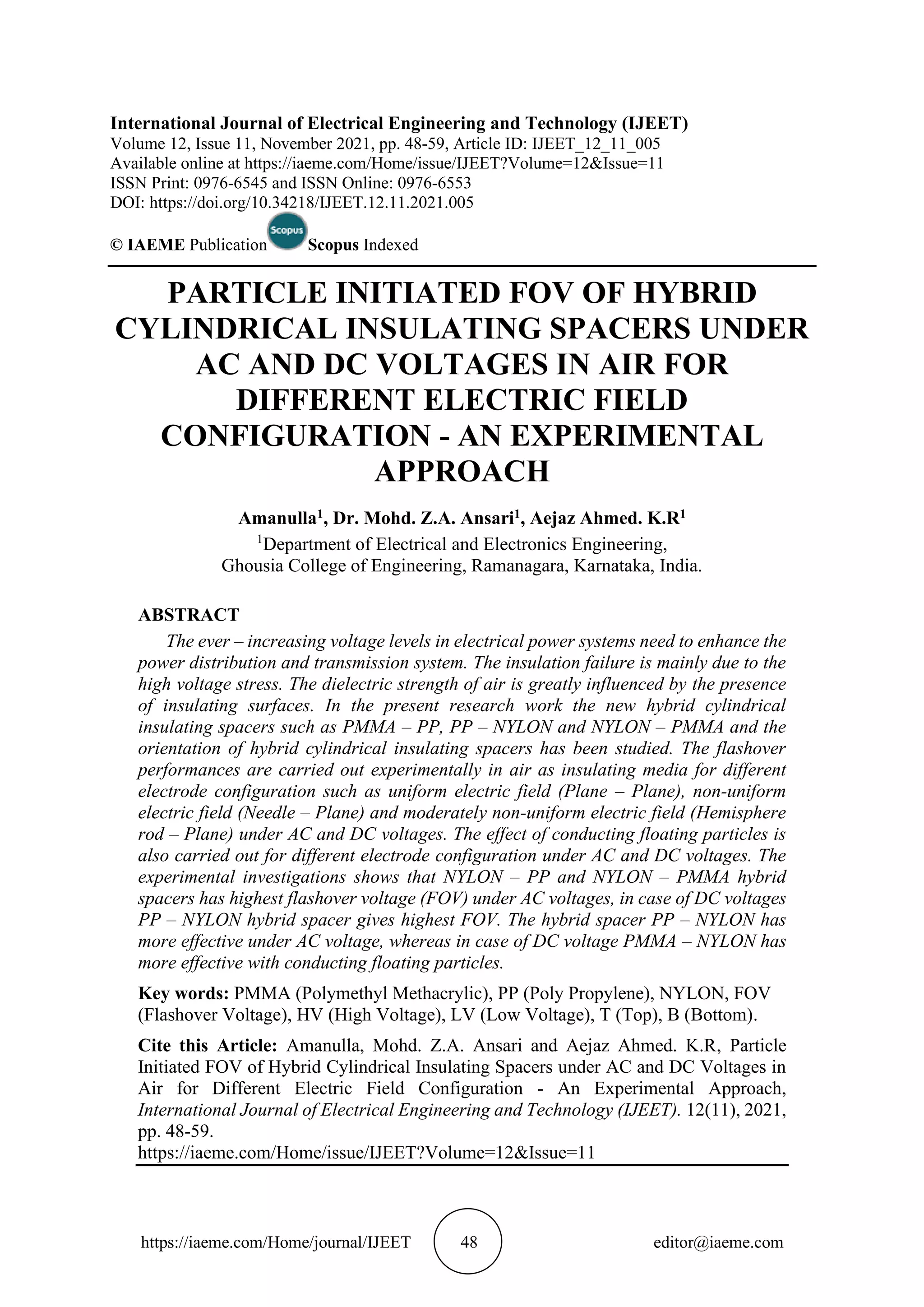
2. EXPERIMENTAL SETUP
The experimental setup to carry the flashover characteristics is as shown in Figure 2. The
insulating spacer is placed tightly between the HV and LV electrode. The high voltage is applied
by varying the auto-transformer, the voltage is gradually increased at an approximate rate of
1kV/sec till the flashover occurs along the surface of the spacer and voltage applied is recorded.
The experiment is carried out for 5 trials and average value is calculated.
Figure 2. Experimental Setup for Measurement of FOV](https://image.slidesharecdn.com/ijeet1211005-211203133416/75/PARTICLE-INITIATED-FOV-OF-HYBRID-CYLINDRICAL-INSULATING-SPACERS-UNDER-AC-AND-DC-VOLTAGES-IN-AIR-FOR-DIFFERENT-ELECTRIC-FIELD-CONFIGURATION-AN-EXPERIMENTAL-APPROACH-2-2048.jpg)
![Amanulla, Mohd. Z.A. Ansari and Aejaz Ahmed. K.R
https://iaeme.com/Home/journal/IJEET 58 editor@iaeme.com
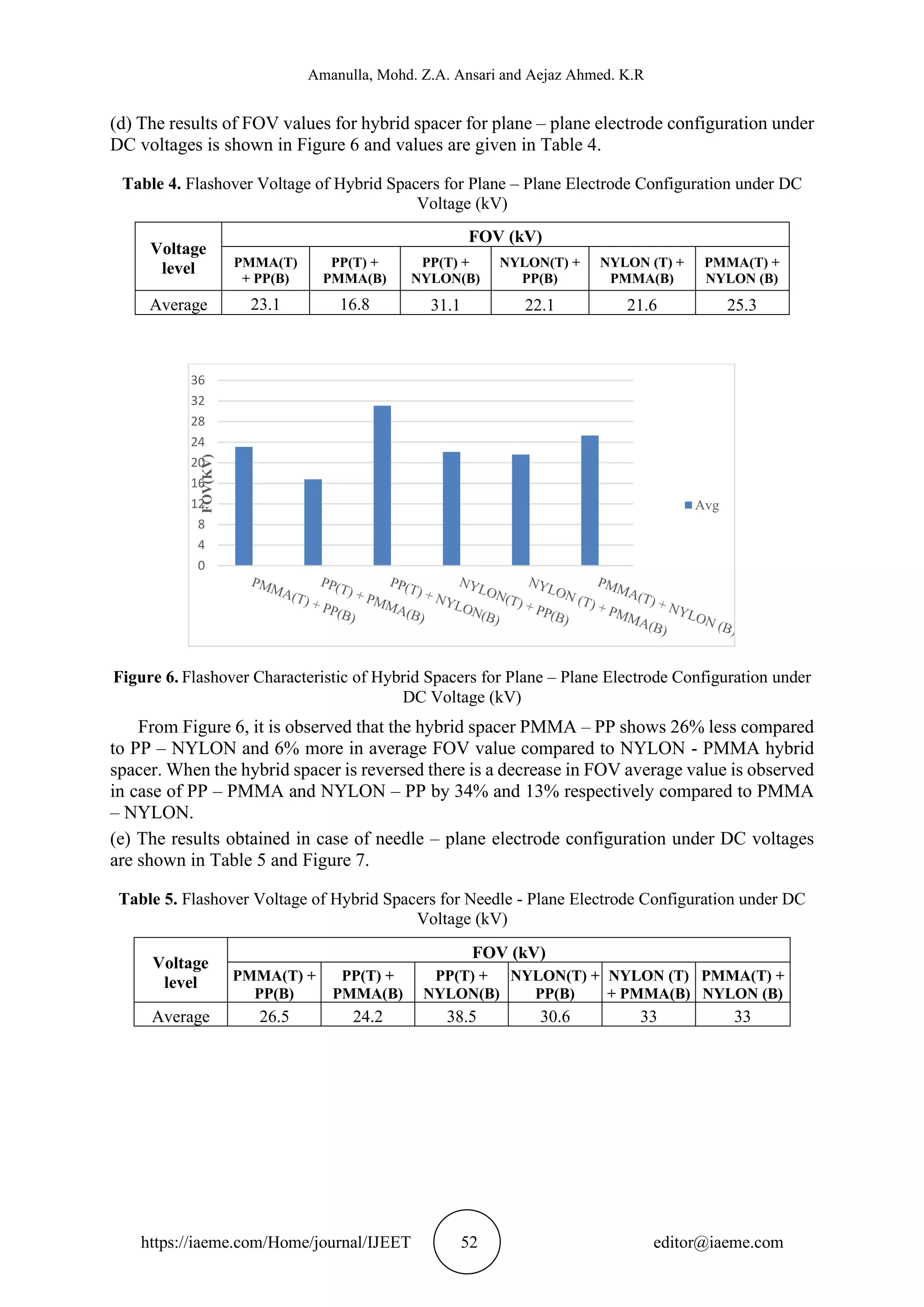
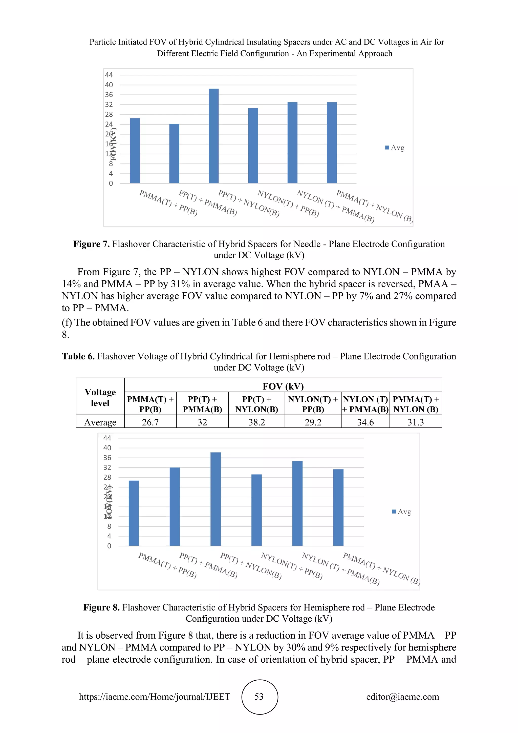
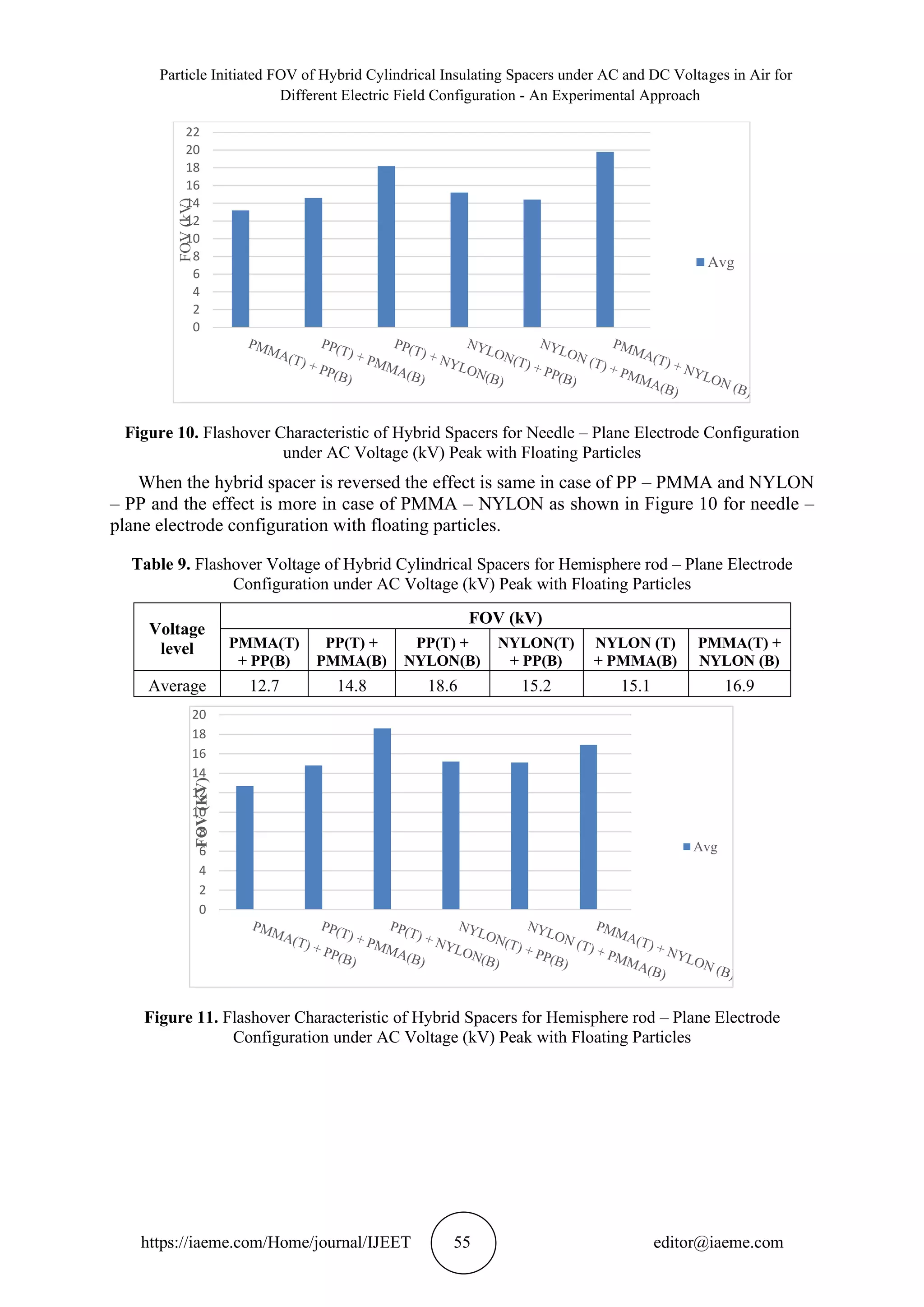
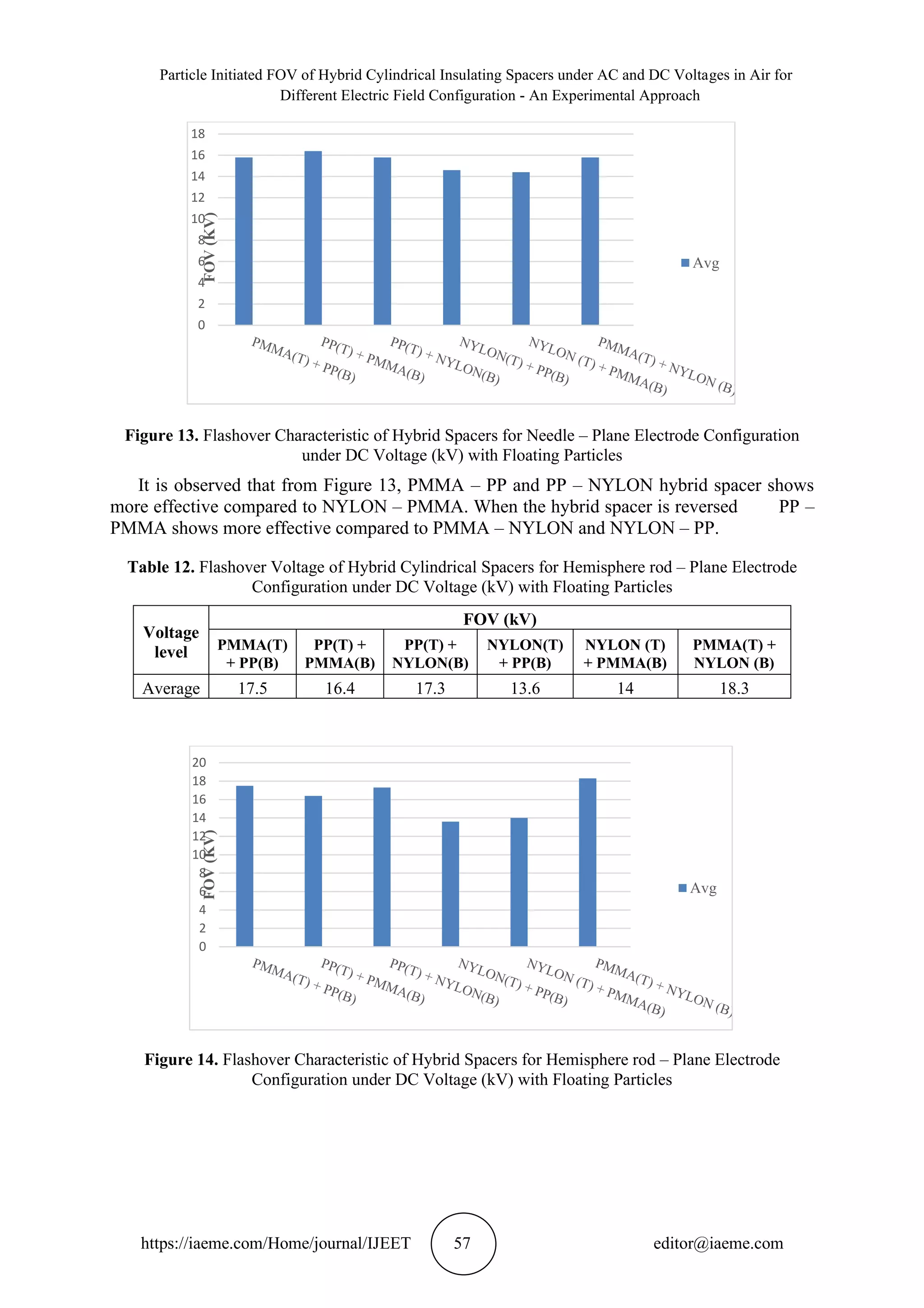
(f) The FOV of hybrid spacers for hemisphere rod – plane electrode configuration with floating
particles given in Table 12 and the FOV characteristics shown in Figure 14, it is observed that
PP – NYLON and PMMA – PP has the same effect compared to NYLON – PMMA is less
effective by 20%. In case of hybrid spacer orientation, it is observed that PMMA – NYLON
has more effective than PP – PMMA and NYLON – PP by 10% and 26% respectively.
4. CONCLUSION
The experimental investigations carried out leads to the following conclusions:
Without Conducting Particles
• Under AC voltages, the PMMA – PP and PP – PMMA is observed highest FOV for
plane – plane electrode configuration and in case of needle – plane electrode
configuration NYLON – PMMA and PMMA – PP shows highest FOV, whereas in case
hemisphere rod – plane PMMA – PP and PMMA – NYLON has highest FOV.
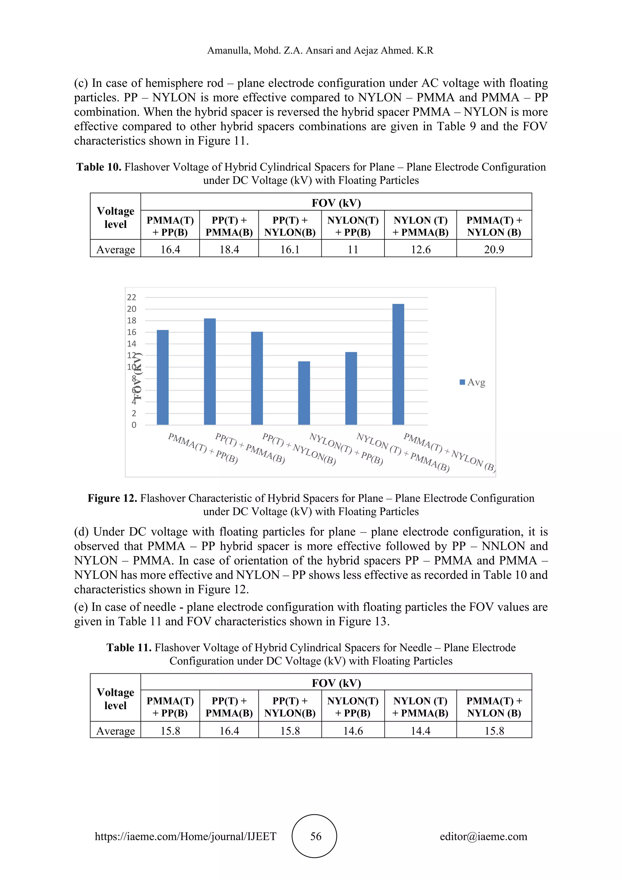
• In case of plane – plane electrode configuration under DC voltages, PP – NYLON and
PMMA – NYLON shows better FOV and in case of needle – plane electrode
configuration PP – NYLON and PMMA – NYLON spacers show better FOV, whereas
in case of hemisphere rod – plane electrode configuration NYLON – PMMA and PP
– NYLON shows better FOV.
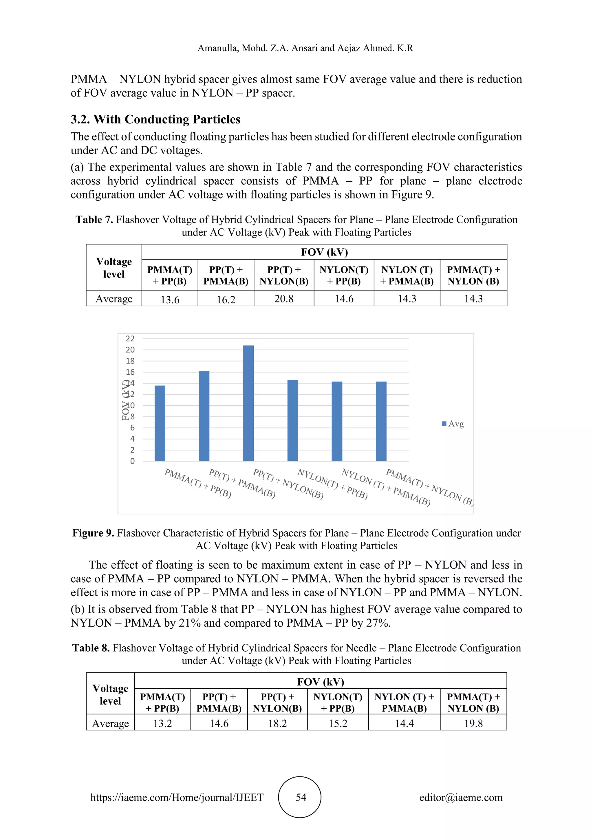
With Conducting Particles
• Under AC voltages, the hybrid spacer PP – NYLON and PP – PMMA seen to be more
effective in case of plane – plane electrode configuration and PP – NYLON and PMMA
– NYLON is more effective in case of needle – plane electrode configuration, whereas
in case of hemisphere rod – plane PP – NYLON shows more effective.
• Under DC voltages, PMMA – PP and PMMA – NYLON is more effective in case of
plane – plane electrode configuration and PP – PMMA has more effective in case of
needle – plane electrode configuration whereas in case of hemisphere rod – plane
PMMA – PP and PMMA – NYLON shows more effective.
ACKNOWLEDGMENTS
The authors thank the authorities of Ghousia College of Engineering, Ramanagaram for
providing the facilities and encouragement for carrying out this research work.
REFERENCES
[1] Li, S., Zhong, L., Li, J., et al.: “A brief history and research progress on solid engineering
dielectrics in chine”, IEEE Electr. Insul. Mag., 2010, 26, (6), pp. 14-21.
[2] Lri, Q.: “ Recent progress of engineering dielectrics”, Sceince Press, Beijing, 1999, 1st
edn.
[3] Shengtao Li, Shihu Yu, Yang Feng, “Progress in and prospects for electrical insulating
materials”, IET Journals, High Voltage, 2016,Vol. 1, Issue 3, pp. 122 – 129.
[4] Josef Kindersberger and christoph Lederle, “Surface Charge Decay on Insulators in Air and
Sulfurhexafluorid-Part II: Measurements”, IEEE Transactions on Dielectric and Electrical
Insulation, Vol 15, No. 4; August 2008.
[5] K. L. Ratnakar, Dr. B. Rajesh Kamath, “Influence of Electrode Configuration on AC
Breakdown Voltages”, International Journal of Research and Sceintific Innovation (IJRSI),
Vol. IV, Issue VI, June 2017, pp. 60-63, ISSN: 2321-2705.](https://image.slidesharecdn.com/ijeet1211005-211203133416/75/PARTICLE-INITIATED-FOV-OF-HYBRID-CYLINDRICAL-INSULATING-SPACERS-UNDER-AC-AND-DC-VOLTAGES-IN-AIR-FOR-DIFFERENT-ELECTRIC-FIELD-CONFIGURATION-AN-EXPERIMENTAL-APPROACH-11-2048.jpg)
![Particle Initiated FOV of Hybrid Cylindrical Insulating Spacers under AC and DC Voltages in Air for
Different Electric Field Configuration - An Experimental Approach
https://iaeme.com/Home/journal/IJEET 59 editor@iaeme.com
[6] Boudenne, A., Ibos, L., Fois, M., et al: “Electrical and thermal behaviour of polypropylene filled
with copper particles”, Compos. A, Appl. Sci. Manuf, 2005, 36,(11), pp. 1545-1554.
[7] Choulkov V.V., “Effect of Electrode surface roughness on electrical breakdown in HV
apparatus”, Dielectrics and Electric Insulation, IEEE Transactions, Volume 12, Issue 1, 2005,
p98-103.
[8] Subratha Karmakar, “An Experimental Study of Air Breakdown Voltage and its Effects on Solid
Insulation”, Journal of Electrical Systems, 8-2 (2012), p 209-217.
[9] R.Brambilla, A.pigini, Electric field strength in typical high voltage Insulation, International
symposium on High voltage Engineering, Zurich, September 1975.
[10] Qiu. Simple Expressions of field non uniformity factor for hemispherically Capped rod plane
gaps, IEEE Trans on E.I, Vol 21, PP 673 – 675, 1986.](https://image.slidesharecdn.com/ijeet1211005-211203133416/75/PARTICLE-INITIATED-FOV-OF-HYBRID-CYLINDRICAL-INSULATING-SPACERS-UNDER-AC-AND-DC-VOLTAGES-IN-AIR-FOR-DIFFERENT-ELECTRIC-FIELD-CONFIGURATION-AN-EXPERIMENTAL-APPROACH-12-2048.jpg)

This research investigates the flashover voltage (FOV) of hybrid cylindrical insulating spacers under AC and DC voltages, focusing on different electric field configurations. Experimental results showed that the nylon-pp and nylon-pmma spacers exhibited the highest FOV under AC voltages, while the pp-nylon spacer demonstrated superior performance under DC. The study emphasizes the influence of conducting floating particles on flashover characteristics across various spacer configurations.