Downloaded 72 times


![IS 456 : 2000
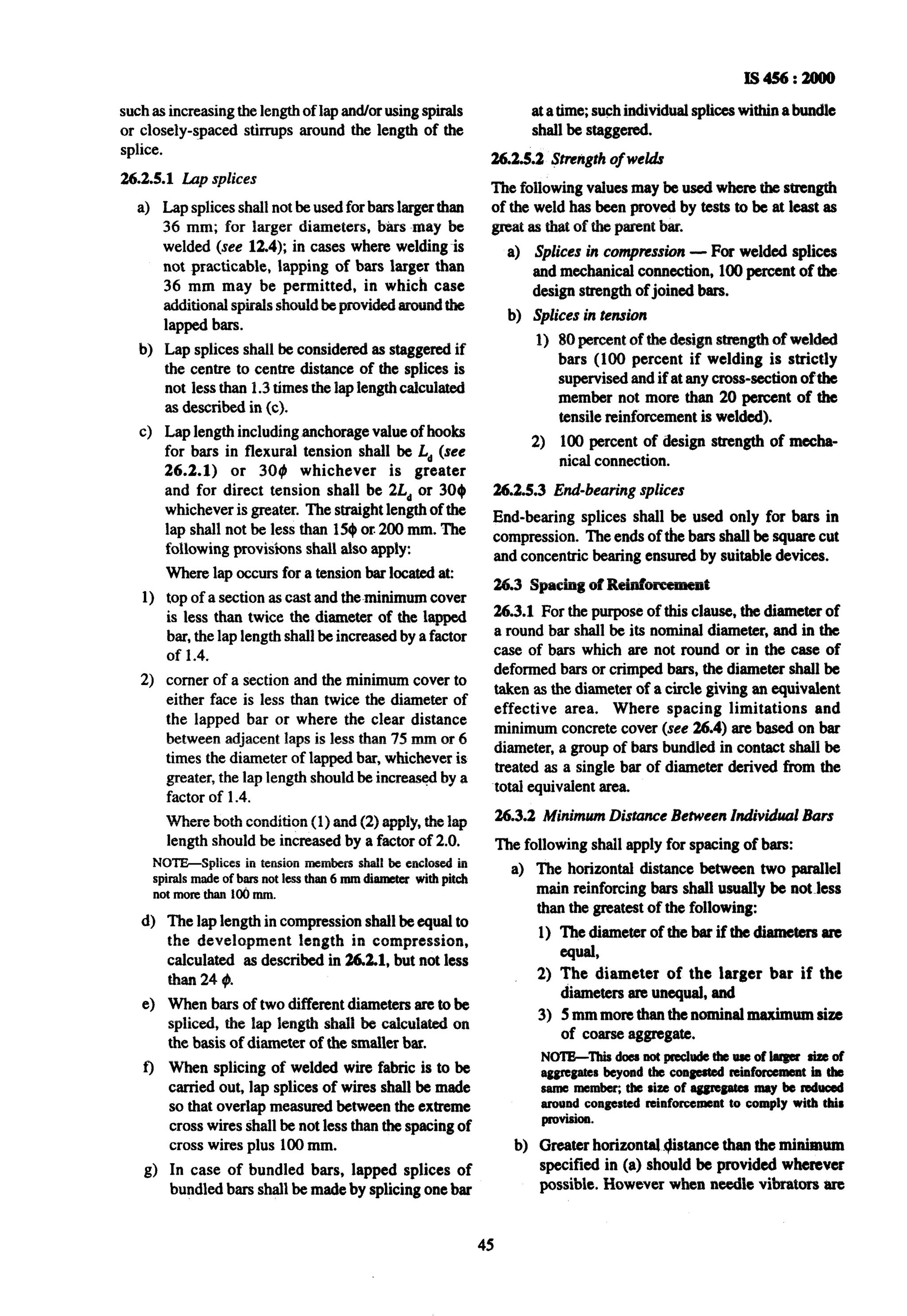
possible after expiry of 28 days from the time of placing
of concrete.
17.6.2 The structure should be subjected to a load equal
to full dead load of the structure plus 1.25 times the
imposed load for a period of 24 h and then the imposed
load shall be removed.
NOTE-Dead load includes self weight of the structural
members plus weight of finishes and walls or partitions, if -any,
as considered in the design.
17.6.3 The deflection due to imposed load only shall
be recorded. If within 24 h of removal of the imposed
loa< the structure does not recover at least 75 percent
of the deflection under superimposed load, the test may
be repeated after a lapse of 72 h. If the recovery is less
than 80 percent, the structure shall be deemed to be
unacceptable.
17.6.3.1 If the maximum deflection in mm, shown
during 24 h under load is less than 4012/D, where 1is
the effective span in m; and D, the overall depth of the
section in~mm, it is not necessary for the recovery to
be measured and the recovery provisions of 17.6.3 shall
not apply.
17.7 Members Other Than Flexural Members
Members other than flexural members should be
preferably investigated by analysis.
17.8 anon-destructive Tests
Non-destructive tests are used to obtain estimation of
the properties of concrete in the structure. The methods
adopted include ultrasonic pulse velocity [see IS 133 11
(Part l)] and rebound hammer [IS 13311 (Part 2)],
probe penetration, pullout and maturity. Non-
destructive tests provide alternatives to core tests for
estimating the strength of concrete in a structure, or
can supplement the data obtained from a limited
number of cores. These methods are based on
measuring a concrete property that bears some
relationship to strength. The accuracy of these methods,
in part, is determined by the degree of correlation
between strength and the physical quality measured
by the non-destructive tests.
Any of these methods may be adopted, in which case the
acceptance criteria shall be agreed upon prior to testing.
31](https://image.slidesharecdn.com/456-130717113704-phpapp02/75/456-32-2048.jpg)

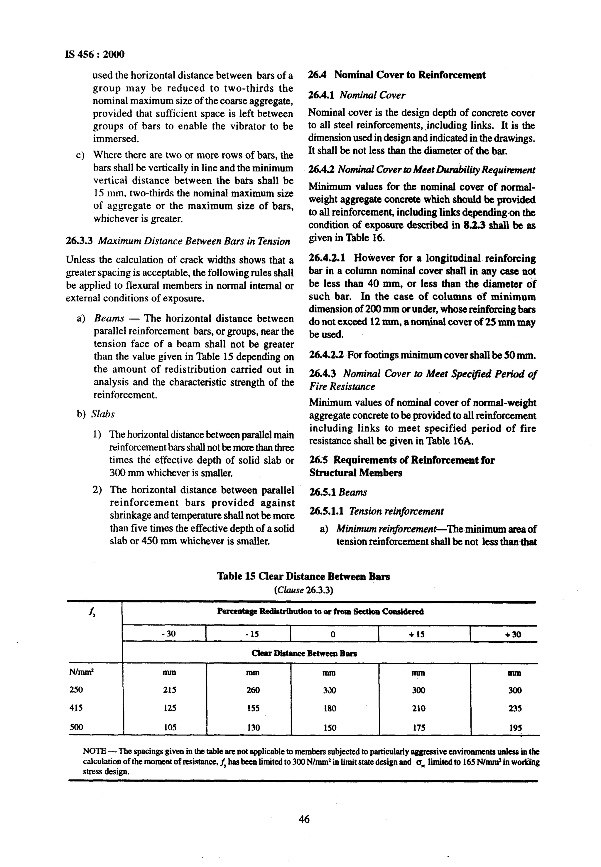
![effects due to temperature fluctuations and shrinkage
and creep can be ignored in &sign calculations.
19.6 Other Forces and Effects
In addition, account shall ‘be taken of the following
forces and effects if they are liable to affect materially
the safety and serviceability of the structure:
4
b)
cl
4
4
9
g)
h)
Foundation movement (see IS 1904),
Elastic axial shortening,
Soil and fluid pressures [see IS 875 (Part S)],
Vibration,
Fatigue,
Impact [see IS 875 (Part 5)],
Erection loads [see IS 875 (Part 2)], and
Stress concentration effect due to point load and
the like.
19.7 Combination of Loads
The combination of loads shall be as given in IS 875
(Part 5).
19.8 Dead Load Counteracting Other L,oadsand
Forces
When dead load counteracts the effects due to other
loads and forces in structural member orjoint, special
care shall be exercised by the designer to ensure
adequate safety for possible stress reversal.
19.9 Design Load
Design load is the load to be taken for use in the
appropriate method of design; it is the characteristic
load in case of working stressmethod andcharacteristic
load with appropriate partial safety factors for limit
state design.
20 STABILITY OF THE STRUCTURE
20.1 Overturning
The stability of a structure as a whole against
overturning shall be ensured so that the restoring
moment shall be not less than the sum of 1.2times the
maximum overturning moment due to thecharac&stic
dead load and 1.4 times the maximum overturning
moment due to the characteristic imposed loads. In
cases where dead load provides the restoring moment,
only 0.9 times the characteristic dead load shall be
considered. Restoring moment ilue to imposed loads
shall be ignored.
20.1.1 The anchorages or counterweights provided
for overhanging members (during construction and
service) should be such that static equilibrium
should remain, even when overturning moment is
doubled.
P
IS456:2800
28.2 Sliding
The strucn~eshall have a factor against sliding of not
lessthan 1.4under the most adverse combination of the
appliedcharact&stic forces. In this case only 0.9 times
the characteristicdead load shall be taken into account.
28.3 Probable Variation in Dead Load
To ensure stability at all times, account shall be taken
of probable variations in dead load during construction,
repair or other temporary measures. Wind and seismic
loading shall be treated as imposed loading.
28.4 Moment Connection
In designing the framework of a building provisions
shall be made-by adequate moment connections or by
a system of bracings to effectively transmit all the
horizontal forces to the foundations.
20.5 Lateral Sway
Under transient wind load the lateral sway at the top
should not exceed H/500, where H is the total height
of the building. For seismic.loading, reference should
be made to IS 1893.
21 F’IRBRBSISTANCR
21.1 A structure or structural element required to have
fire resistance should be designed to possess an
appropriate degree of resistance to flame penetration;
heat transmission and failure. The fire resistance of a
structuralelement is expressed in terms of time in hours
in accordance withIS 1641. Fire resistance of concrete
elements depends upondetails of member size, cover
to steel reinforcement detailing and type of aggregate
(normal weight or light weight) used in concrete.
General requirements for fue protection are given in
IS 1642.
21.2 Minimum requirements of concrete cover and
member dimensions for normal-weight aggregate
concrete members so as to have the required fire
resistance shall be in accordance with 26.4.3 and
Fig.1respectively.
21.3 The reinforcement detailing should reflect the
changing pattern of the structural section and ensure
that both individual elements and the structure as a
whole contain adequate support, ties, bonds and
anchorages for the required fire resistance.
21.3.1 Additional measures such as application of tire
resistant finishes, provision of fire resistant false
ceilings and sacrificial steel in tensile zone, should be
adopted in case the nominal cover required exceeds
40 mm for beams and 35 mm for slabs, to give
protection against~spalling.
21.4 Specialist literature may be referred to for
determining fire resistance of the structures which have
not been covered in Fig. 1 or Table 16A.
33](https://image.slidesharecdn.com/456-130717113704-phpapp02/75/456-34-2048.jpg)


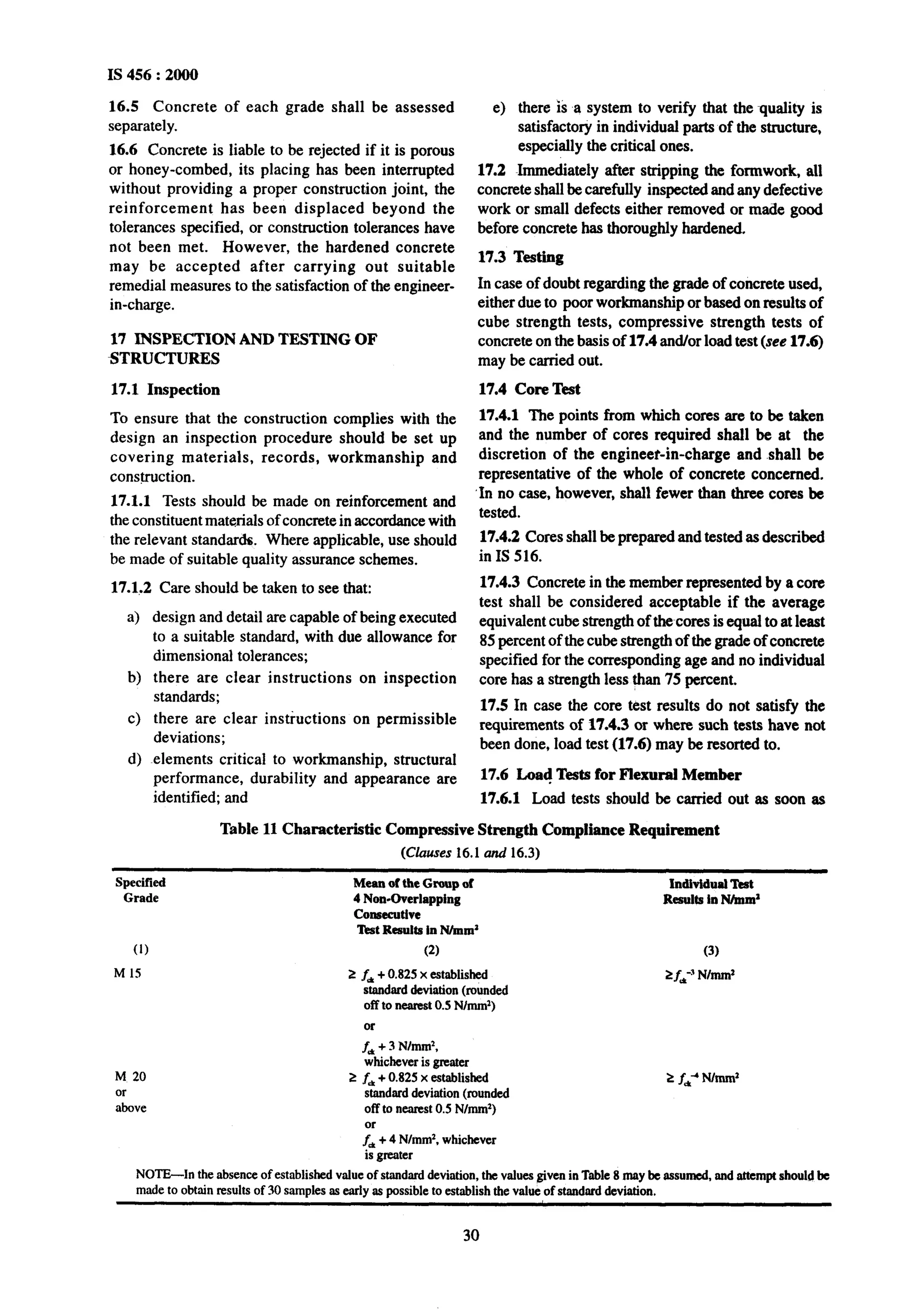
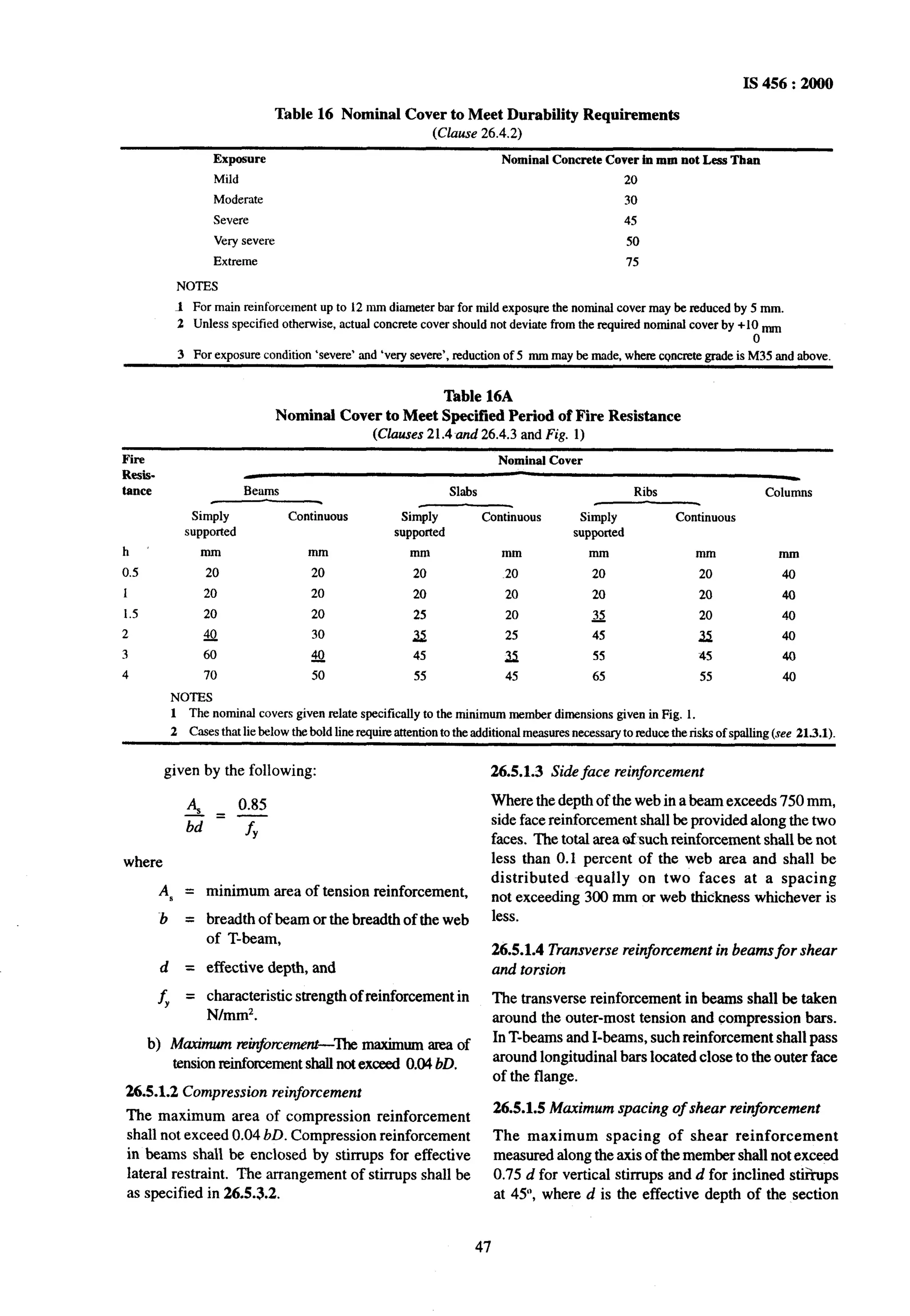
![24.3.2.3 Any other recognized method of analysis for
cases of slabs covered by 24.3.2.1 and 24.3.2.2 and
for all other cases of slabs may be used with the
approval of the engineer-in-charge.
24.3.2.4 The critical section for checking shear shall
be as given in 34.2.4.1.
24.4 Slabs Spanning in ‘ho Directions at Right
Angles
The slabs spanning in two directions at right angles
and carrying uniformly distributed load may be
designed by any acceptable theory or by using
coefficients given in Annex D. For determining
-bending moments in slabs spanning in two directions
at right angles and carrying concentrated load, any
accepted method approved by the engineer-in-charge
may be adopted.
NOTE-The most commonly used elastic methodsan based
on Pigeaud’sorWester-guard’stheoryandthe most commonly
usedlimitstateof collupsemethodis basedonJohansen’syield-
line theory.
24.4.~ Restrained Slab with Unequal Conditions at
Adjacent Panels
In some cases the support moments calculated from
Table 26 for adjacent panels may differ significantly.
The following procedure may be adopted to adjust
them:
a)
b)
cl
d)
Calculate the sum of moments at midspan and
supports (neglecting signs).
Treat the values from Table 26 as fixed end
moments.
According to the relative stiffness of adjacent
spans, distribute the fixed end moments across
the supports, giving new support moments.
Adjust midspan moment such that, when added
to the support moments from (c) (neglecting
I$456 : 2000
signs), the total should be equal to that from (a).
If the resulting support moments are signifi-
cantly greater than the value from Table 26, the
tension steel over the supports will need to be
extended further. The procedure should be as
follows:
1)
2)
3)
4)
Takethe spanmoment asparabolic between
supports: its maximum value is as found
from (d).
Determine the points of contraflexure of the
new support moments [from (c)] with the
span moment [from (l)].
Extend half the support tension steel at each
end to at least an effective depth or 12 bar
diameters beyond the nearest point of
contraflexure.
Extend the full area of the support tension
steel at each end to half the distance from
(3).
24.5 Loads on supporting Beams
The loads on beams supporting solid slabs spanning
in two directions at right angles and supporting
uniformly distributed loads, may be assumed to be in
accordance with Fig. 7.
25 COMPRESSION MEMBERS
25.1 Defdtions
25.1.1 Column or strut is a compression member, the
effective length of which exceeds three times the least
lateral dimension.
25.1.2 Short and Slender Compression Members
A compression member may be considered as short
1 1
when both the slenderness ratios Cx and x are less
D b
than 12:
LLOAD
-0
IN THIS SHADED
AREA To BE CARRIED
&Y BEAM ‘6’
-LOAD IN THIS SHADED AREA
TO BE CARRIED By BEAM ‘A’
FIG.7 LoADCAxnranBY !bPPGKl7NGBEAMS
41](https://image.slidesharecdn.com/456-130717113704-phpapp02/75/456-42-2048.jpg)


![NOTE - Pedestal is a compression member, the effective
length of which does not exceed three times the least lateral
dimension.
26.5.3.2 Transverse reinforcement
a>General-A reinforced concrete compression
member shall have transverse or helical
reinforcement so disposed that every longitu-
dinal -bar nearest to the compression face
has effective lateral support against buckling
subject to provisions in (b). The effective lateral
support is given by transverse reinforcement
either in the form of circular rings capable of
taking up circumferential tension or by
polygonal links (lateral ties) with internal angles
not exceeding 135’. The ends of the transverse
reinforcement shall be properly anchored
[see 26.2.2.4 (b)].
b) Arrangement of transverse reinforcement
1)
2)
3)
4)
If the longitudinal bars are not spaced more
than 75 mm on either side, transverse
reinforcement need only to go round comer
and alternate bars for the purpose of
providing effective lateral supports
(see Fig. 8).
If the longitudinal bars spaced at a distance
of not exceeding 48 times the diameter of
the tie are effectively tied in two directions,
additional longitudinal bars in between these
bars need to be tied in one direction by open
ties (see Fig. 9).
Where the longitudinal reinforcing bars in
a compression member are placed in more
than one row, effective lateral support to the
longitudinal bars in the inner rows may be
assumed to have been provided if:
i>
ii)
transverse reinforcement is provided for
the outer-most row in accordance with
26.5.3.2, and
no bar of the inner row is closer to the
nearest compression face than three
times the diameter of the largest bar in
the inner row (see Fig. 10).
IS 456 : 2000
reinforcement need not, however, exceed
20 mm (see Fig. 11).
c) Pitch and diameter of lateral ties
1) Pitch-The pitch of transverse reinforce-
ment shall be not more than the least of the
following distances:
i) The least lateral dimension of the
compression members;
ii) Sixteen times the smallest diameter of
the longitudinalreinforcement bar to be
tied; and
iii) 300 mm.
2) Diameter-The diameter of the polygonal
links or lateral ties shall be not less than one-
fourth of the diameter of the largest
longitudinal bar, and in no case less than
16 mm.
d) Helical reinforcement
1) Pitch-Helical reinforcement shall be of
regular formation with the turns of the helix
spaced evenly and its ends shall be anchored
properly by providing one and a half extra
turns of the spiral bar. Where an increased
load on the column on the strength of the
helical reinforcement is allowed for, the pitch
of helical turns shall be not more than 7.5mm,
nor more than one-sixth of the core diameter
of the column, nor less than 25 mm, nor less
than three times the diameter of the steel bar
forming the helix. In other cases, the
requirements of 26.5.3.2 shall be complied
with.
2)
26.5.3.3
The diameter of the helical reinforcement
shall be in accordance with 26.5.3.2 (c) (2).
ln columns where longitudinal bars are offset
Where the longitudinal bars in a com-
pression member are grouped (not in
contact) and each group adequately tied with
transverse reinforcement in accordance with
26.5.3.2, the transverse reinforcement for the
compression member as a whole may be
provided on the assumption that each group
is a single longitudinal bar for purpose of
determining the pitch and diameter of the
transverse reinforcement in accordance with
26.5.3.2. The diameter of such transverse in 26.2.5.1.
at a splice, the slope of the inclined portion of the bar
with the axis of the column shall not exceed 1 in 6,
and the portions of~thebar above and below the offset
shall be parallel to the axis of the column. Adequate
horizontal support at the offset bends shall be treated
as a matter of design, and shall be provided by metal
ties, spirals, or parts of the floor construction. Metal
ties or spirals so designed shall be placed near (not
more than eight-bar diameters from) the point of bend.
The horizontal thrust to be resisted shall be assumed
as one and half times the horizontal components of
the nominal stress in the inclined portion of the bar.
Offset bars shall be bent before they are placed in the
forms. Where column faces are offset 75 mm or more,
splices of vertical bars adjacent to the offset face shall
be made by separate dowels overlapped as specified
49](https://image.slidesharecdn.com/456-130717113704-phpapp02/75/456-50-2048.jpg)


![IS 456 : 2000
NOTES
1 Wheremorethaaonetypeof shearreinforcementis used
to reinforcethesameportionof thebeam,thetotalshear
resistanceshallbe computedasthesumof theresistance
forthe varioustypes separately.
2 Theareaofthestim~psshallnotbelessthantheminiium
specified in 265.1.6.
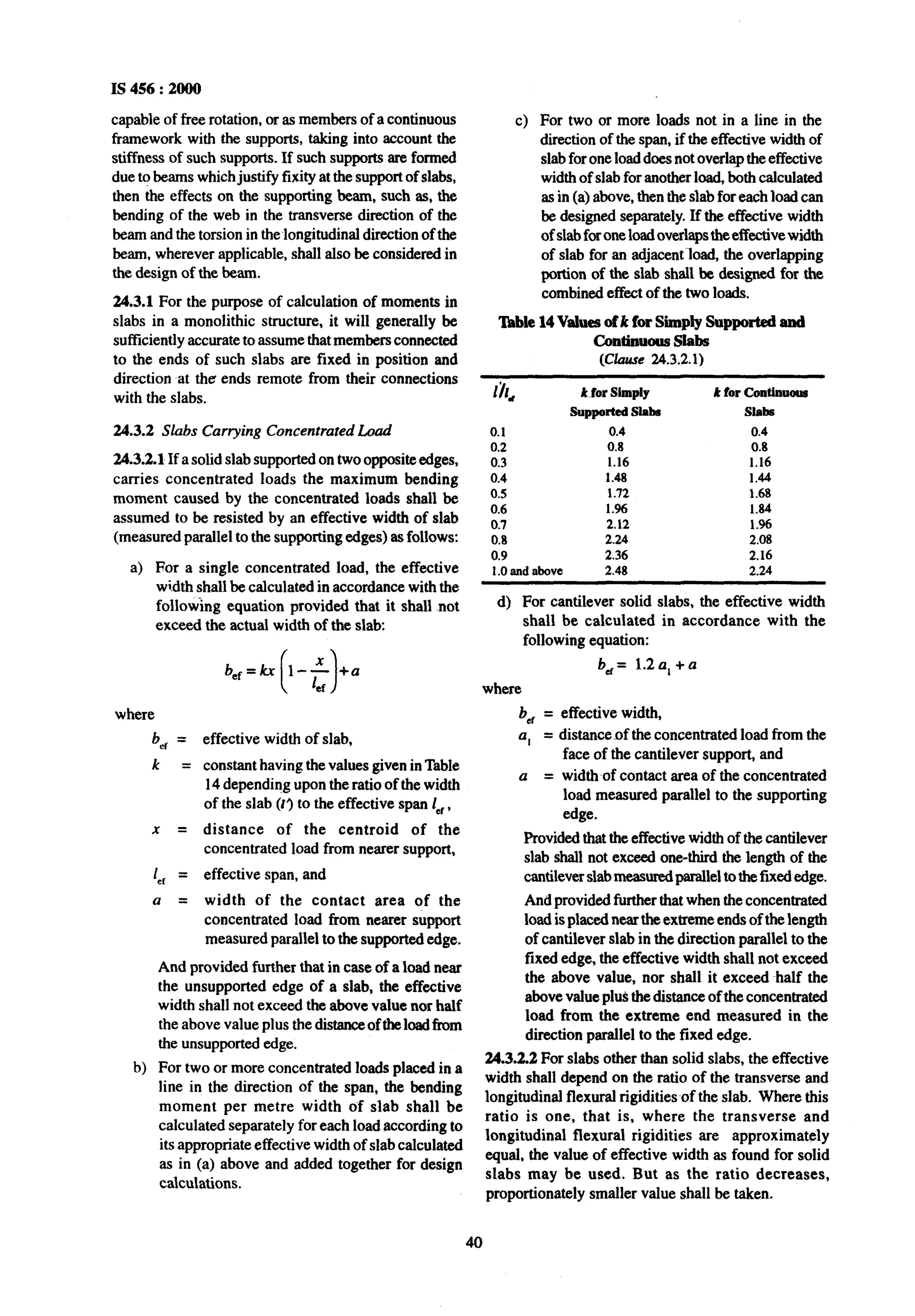
40.5 Enhanced Shear Strength of Sections Close
to supports
40.5.1 General
Shear failure at sections of beams and cantilevers
without shear reinforcement will normally occur on
plane inclined at an angle 30” to the horizontal. If the
angle of failure plane is forced to be inclined more
steeply than this [because the section considered
(X - X) in Fig. 24 is close to a support or for other
reasons], the shear force~requiredto produce failureis
increased.
The enhancement of shear strength may be taken
into account in the design of sections near a support
by increasing design shear strength of concrete to
2d z, /a, provided that design shear stress at the face
of the support remains less than the values given in
Table 20. Account may be taken of the enhancement
in any situation where the section consideredis closer
to theface of a supportorconcentratedloadthantwice
the effective depth, d. To be effective, tension
reinforcementshould extend on each side of the point
whereit is intersectedby a possible failureplane fora
distance at least equal to the,effective depth, or be
provided with an equiv.dent anchorage.
40.52 Shear Reinforcement for Sections Close to
supports
If shear reinforcement is required, the total area of this
X
is given by:
As=avb(zV-2d’tc/aV)10.87fy20.4a,b/0.87fy
This reinforcementshouldbeprovided withinthemiddle
three quarters of a,, where aVis less thand, horizontal
shear reinforcement will be effective than vertical.
40.5.3 Enhanced Shear Strength Near Supports
(Simplified Approach)
The procedure given in 40.51 and 40.5.2 may beused
for all beams. However for beams carrying generally
uniform load or where the principal load is located
farther than 26 from the face of support, the shear
stress maybe calculated at a section a distance d from
the face of support. The value of 2, is calculated in
accordance with Table 19 and appropriate shear
reinforcement is provided at sections closer to the
support,no furthercheck for shearat such sections is
required.
41 LIMlT STATE OF COLLAPSE : TORSION
41.1 General
In structures, where torsion is required to maintain
equilibrium, members shall be designed for torsion in
accordancewith41.2,41.3 and41A. However,forsuch
indeterminatestructureswheretorsioncanbeeliminated
by releasingredundantrestraints,no specific design for
torsion is necessary, provided torsional stiffness is
neglectedinthecalculationof internalforces.Adequate
controlofanytorsionalcrackingis providedby theshear
reinforcementas per 40.
NOTE-The approachto desip in this clause is as follows:
Torsionalreinforcementis not calculatedseparatelyfromthat
requiredfor beading and shear.Insteadthe total longitudinal
reinforcementis determinedfor a fictitious bending moment
which is a function of actual bending moment and torsion;
NOTE-The shearcausingfailureis thatactingon sectionX-X.
FIG.24 SHIMFAILURENEARSIJFWI~~~
74](https://image.slidesharecdn.com/456-130717113704-phpapp02/75/456-75-2048.jpg)


![IS 456:2000
B-5.2.3.1 For slabs, Z, shall not exceed half the value
of Z,milxgiven in Table 24.
B-5.3 Minimum Shear Reinforcement
When zv is less than zCgiven in Table 23, minimum
shear reinforcement shall be provided in accordance
with 26.5.1.6.
B-5.4 Design of Shear Reinforcement
When zv exceeds zC given in Table 23, shear
reinforcement shall be provided in any of the following
forms:
a) Vertical stirrups,
b) Bent-up bars along with stirrups, and
c) Inclined stirrups.
Where bent-up bars are provided, their contribution
towards shear resistance shall not be more than half
that of the~totalshear reinforcement.
Shear reinforcement shall be provided to carry a shear
equal to V- zC.bd. The strength of shear reinforcement
V, shall be calculated as-below:
a) For vertical stirrups
b) For inclined stirrups or a series of bars bent-up
at different cross-sections:
v,= as, 4, d
sV
(sina + cosa)
c) For single bar or single group of parallel-bars,
all bent-up at the same cross-section:
V, = 6,” A,, sin 01
where
As” = total cross-sectional area of stirrup legs
or bent-up bars within a distance,
spacing of the stirrups or bent-up bars
along the length of~themember,
design shear strength of the concrete,
breadth of the member which for
flanged beams, shall be taken as the
breadth of the web b,
permissible tensile stress in shear
reinforcement which shall not be taken
a =
d =
greater than 230 N/mmz,
angle between the inclined stirrup or
bent-up bar and the axis of the member,
not less than 45”,and
effective depth.
NOTE -Where more than one type of shear reinforcement is
used to reinforcethe same portion of the beam, the total shear
resistance shall be computed as the sum of the resistance for the ’
varioustypesseparately. The nrea of the stirrups shall not be
less than the minimum specified in 26.5.1.6.
B-5.5 Enhanced Shear Strength of Sections Close
to supports
Be5.5.1 General
Shear failure at sections of beams and cantilevers
without shear reinforcement will normally occur on
plane inclined at an angle 30”to the horizontal. If the
angle of failure plane is forced to be inclined more
steeply than this [because the section considered
(X - X) in Fig. 24 is close to a support or for other
reasons], the shear force required to produce failure is
increased.
The enhancement of shear strength may be taken
into account in the design of sections near a support
by increasing design shear strength of concrete, z,
to 2d zClav provided that the design shear stress at
the face of support remains less than the values
given in Table 23. Account may be taken of the
enhancement in any situation where the section
considered is closer to the face of a support of
concentrated load than twice the effective depth, d.
To be effective, tension reinforcement should extend
on each side of the point where it~isintersected by a
possible failure plane for a distance at least equal to
the effective depth, or be provided with an
equivalent anchorage.
B-5.5.2 Shear Reinforcement for Sections Close to
Supports
If shear reinforcement is required, the total area of this
is given by:
As = avb ( Z, -2d ze/av )/0.87fy 2 0.4avb/0.87fy
This reinforcement should be provided within the
middle three quarters of a”. Where av is less than d,
horizontal shear reinforcement will be more effective
than vertical.
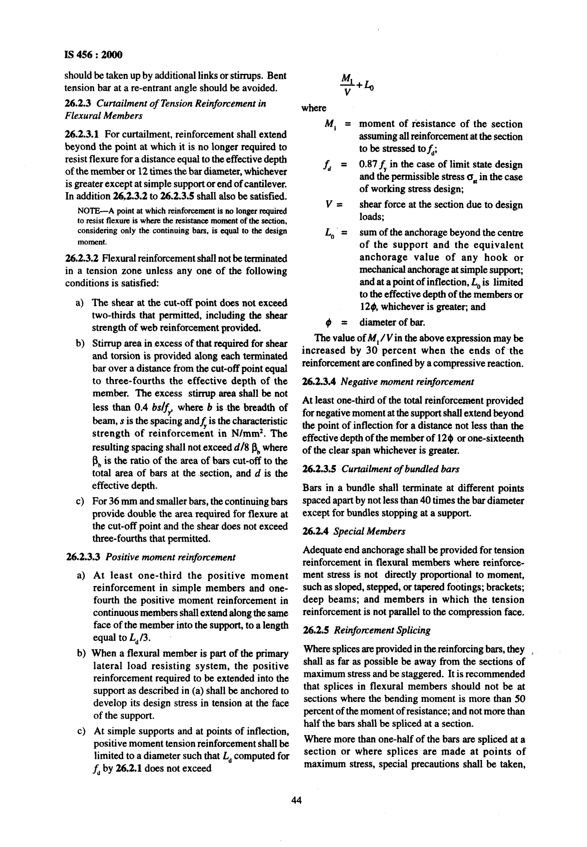
Table 24 Maximum Shear Stress, z, ,_, N/mm*
(CluusesB-52.3, B-5.2.3.1,B-5.5.1 andB-6.3.1)
Concrete Grade M 15
z Nhnzc,,,yx, 1.6
M 20
1.8
M 25
1.9
M 30
2.2
M 35
2.3
M40andabove
2.5
85](https://image.slidesharecdn.com/456-130717113704-phpapp02/75/456-86-2048.jpg)


![Amend No. 1 to IS 4S6: 2000
(Page 33, clause 21.3, line 2) — Substitute !action’ )lor ‘section’.
[ Page 37, clause 23.1.2(c)] — Substitute ‘L+‘@r ‘b,’, ‘lO’@ ‘l;, ‘b’/br ‘b’ and ‘bW’for ‘bW’m the formulak.
(Page 46, clause 26.4.2 ) – Substitute ‘8.2.2’for ‘8.2.3’.
[Page 49, clause 26.5.3.2 (c) (2), last line ] — Substitute ‘6 mm’ for ’16 mm’.
(Page 62, clause 32.2.5 ) – Substitute ‘H:’ for ‘HW~’in the explamtion of e,.
(Page 62, clause 32.3.1, line 4) – Substitute ‘32.4’for ‘32.3’.
[ Page 62, clause 32.4.3 (b), line 6 ] — Insert ‘~eW’between the words ‘but’ and ‘shall’.
[ Page 65, clause 34.2.4.l(a), last line] — Insert the following after the words ‘depth of footing’:
‘in case of footings on soils, and at a distsnm equal to half the e~fective depth of footing’.
(Page 68, Tab& 18, CO14 ) — Substitute ‘-’ for ‘1.0’ against the Load Combination DL + IL.
(Page 72, clause 40.1 ) – Substitute ‘bd’ for ‘b~’ in the formula.
(Page 83, clause B-4.3, line 2) —Delete the word ‘and’.
(Page 85, clause B-5.5.l,para 2, line 6 ) – Substitute ‘Table 24’ for ‘Table 23’.
(Page 85, clause B-5.5.2 ) — Substitute the following for the existing formula:
‘A, = avb (tv-2d~c I av) /a,v z 0.4 avb / 0.87 fy’
(Page 90, clause D-1.11, line 1 ) — Substitute ‘Where” for ‘Torsion’.
(Page 93, Fig. 27) — Substitute ‘lJ1’ for ‘U’.
(Page 95, Anncw F ):
q
a) The reference to Fig. 28 given in column 1 of the text along with the explanation of the symbols used in the Fig.
28 given thereafter maybe read just before the formula given for the rectangular tension zone.
b) Substitute ‘compression’ for ‘compression’ in the explanation of symbol ‘a ‘ .
(Pages 98 to 100, Annex H) – Substitute the following for the existing Annex:
ANNEX H
(Foreword)
COMMTfTEE COMPOSITION
Cement snd Concrete Sectional Committee, CED 2
Chairman
DR H. C. VWESVARAYA
‘Chandnks’. at 15* Cmaa. 63-64 East park Road.
Medurs
DRS. C. AHLUWAUA
SHRIV. BAIASUSrMWUWAN
SHIUR. P. SINGH(Alternate)
SHFUG. R. BHARtmwtr
SHRIA K CHADHA
SHIUJ.R. !ML(Ahenrute)
CMrrwENGtmeR(DtmoN)
SUFSRNIINDING ENOtNSER&S) (Alternate)
CIMIFENOINSWI@IAVGAMDAMI
SUFSmmNOINGENoumut(QCC) (Alterrrde)
CHIEFthGINSF!JI(RBswRcH)-cuM-IlttecmR
R@sSARCHOFPICaR@ONCREIIi‘kHNOLOGY)
(Akernde)
A4atieawarsmBangalore-560 003 ‘
Reprcssnting
OCL India I& New Delhi
Directorate Geneml of Supplies and Dwpoask New Delhi
B. G. Shirke Construction Technology L@ Puoe
Hindustsn Prefab IJmite4 New Delhi
Central Pubtic WortraDepartment, New Delhi
Sardar Samvar Namrada Nigsm L&t,Gamfhinagar
Irrigation aridPower Research Inatihrte. Amritssr
2
(contimdrmpsge3)](https://image.slidesharecdn.com/456-130717113704-phpapp02/75/456-104-2048.jpg)


SHRIK. L PRUrHJ
SHRIJ. R. GAtSR.JEL(A/terrrufe)
SHrtIB. D. RAHALIWR
SHRIU. S. P. VERMA(Alternate)
SHRI HANUMANTHARAO
SHRIG. RAMAKRtStlNAN(Alternate)
SHtoS. A. REDDI
DR N. K. NAYAK (Ahernde)
S}IRI S. C. SAWHNEY
StiRl R. P. MEtlR071r,4(Ahernde)
PROFM. S. SHEtTt
SHRIN. K SINHA
SIIRI B. T. UNWAtJA
Convener
DRC. RAJKUMAR
Members
DRANILKUMAR
SIIRJV. K. GHANEKAR
PROFA. K. JAIN
SHRI L K. JAIN
SHRIJOSE KURtAN
DR S. C. MAtTS
DR A. K MIITAL
S}IR} S. A. REDOI
DR V. THIRWENGDAM
Members
DR C. RAJKUMAR
SIIRI S. A. REDDI
Representing
Structural Engineering Research Centre (cSIR), Chennai
National Building Construction Corporation Ltd. New Delhi
Nuclear Power Corporation Ltd, New Delhi
A.P. Engineering Research Laboratories, Hyderabad
Gammon India Ltd. Mumbai
Engineers India Ltd, New Delhi
Indian Concrete Institute, Cherrnai
Ministry of Surface Transport (Roads Wing), New Delhi
In personal capacity
Panel for Revision of IS 456, CED 2:2/P
Reprwenting
National Council for Cement and Building Materials, Ballabgarh
National Council for Cement and Building Materials, Ballabgarh
Structural Engineering Research Cenire (cSIR), Ghaziabsd
University of Roorkee, Roorkee
In personal capacity
Central Public Works Department, New Delhi
National Council for Cement and Building Materials, Ballabgarh
Central Public Works Department, New Delhi
Gammon India I@ Mumbai
School of Planning and Architecture, New Delhi
Special Ad-Hoc Group for Revision of 1S 456
Chairman
DR H. C. VISVESVARAYA
‘Chandrika’, at 15* Cross, 63-64 East Park Road,
Malleswaram, Bangalore-560 003
Representbig
National Council for Cement and Building Materials, Ballabgarh
Gammon India Idd, Mumbai
(CED2)
Printed at New Incha Prmturg Press. KhurJa. India](https://image.slidesharecdn.com/456-130717113704-phpapp02/75/456-107-2048.jpg)
![AMENDMENT NO. 2 SEPTEMBER 2005
TO
1S 456:2000 PLAIN AND REINFORCED CONCRETE —
CODE OF PRACTICE
(Fourth A?eviswn )
( Page 13, clause 5.2.1.1, line 1 ) — Substitute ‘IS 3812 (Part 1)’ for
‘Grade 1 of IS 3812’.
( Page 13, clause 5.2.1.2 and corresponding Note ) — Substitute the
following for the existing
‘Silica fime conforming to IS 15388 maybe used as part replacement of cement
provided uniform blending with the cement is ensured.
NOTE — Silica fume is usually used in proportion of 5 to 10 percent of the cement
content of a mix.’
( Page 13, Note under clause 5.21.3, line 5 ) — Substitute ‘be’ for ‘range
Ikom being’.
( Page 25, clause 10.3.3, line 4 ) — Delete the word ‘an&.
( Page 65, clause 34.2.4.2, line 1 ) — Substitute ‘on’ for ‘or’.
[ Page 65, ckuw 34.3.l(a), line 2 ] — Delete the words ‘extending in eaeh
direction’.
( Page 66, c!ause 34.4.3, line 5 ) — Substitute ‘not’ for ‘no’.
( Page 78, Annex A ) — Substitute the following for the existing entries for
[S 3812:1981:
‘IS No. Title
IS 3812 (Part 1): 2003 Specification for pulverized fuel ash: Part 1 For
use as pozzolana in cement cement mortar and
concrete (second revision)’
( Page 79, Annex A ) — Add the following at the end
‘IS No. Title
1S 15388:2003 Specifkation for silica fume’
1](https://image.slidesharecdn.com/456-130717113704-phpapp02/75/456-108-2048.jpg)
![Amend No. 2 to IS 456:2000
( Page 80, B-2.1.1, informal table) — Insert the following in the table:
‘
M55
5,6
,
( Page 81, Table 21 ) — Insert the following row after the last row:
‘(1) (2)
M55 17.5
( Page 91, Table 26, Case No. 2,
Discontinuous’ for ‘One Short Edge Continuous’.
(3) (4)
13.0 1.5’
CO1 2 ) — Substitute ‘Oue Short Edge
[ Page 96, G1.l(c), formula ] — Substitute ‘kf@ti’ for ‘A4.,lti’.
[ Page 96, G1.l(d), last line] — Substitute ‘38.1’~or ‘39.1’.
.
(CED2)
Reprography UniG BIS, New D@ India
2](https://image.slidesharecdn.com/456-130717113704-phpapp02/75/456-109-2048.jpg)

This document provides the full text of the Indian Standard IS 456:2000 Code of Practice for Plain and Reinforced Concrete. Some key details include: - It establishes standards and guidelines for the design, materials, workmanship, construction, and testing of plain and reinforced concrete structures. - Major revisions from previous versions include expanded guidance on durability requirements, modified acceptance criteria for concrete, and the inclusion of higher strength concrete grades. - It contains sections on materials, design considerations, structural design principles, and testing/inspection. The limit state and working stress methods for structural design are both included.


