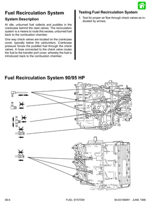
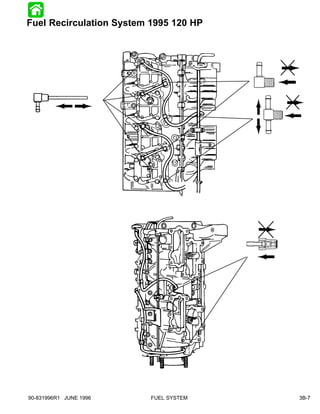
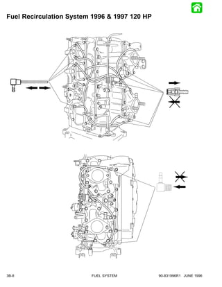
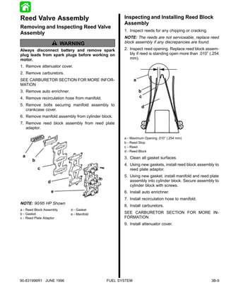
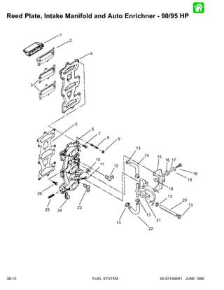
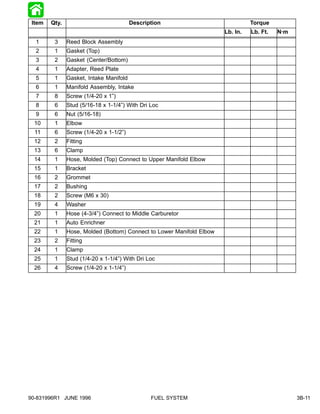
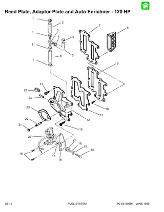
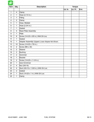
This document provides information on fuel systems and carburetion for marine engines. It discusses fuel pumps, fuel recirculation systems, reed valve assemblies, and auto enrichners. Diagrams are included showing the components and connections of these systems for 90/95 HP and 120 HP engines. Instructions are provided for removing, inspecting, and installing fuel pumps, reed valve assemblies, and related components.
Suzuki DT15C (1988) outboard motors Service Repair Manualfudjfjjskwekmem
This is the Highly Detailed factory service repair manual for theSUZUKI DT15C (1988) OUTBOARD MOTORS, this Service Manual has detailed illustrations as well as step by step instructions,It is 100 percents complete and intact. they are specifically written for the do-it-yourself-er as well as the experienced mechanic.SUZUKI DT15C (1988) OUTBOARD MOTORS Service Repair Workshop Manual provides step-by-step instructions based on the complete dis-assembly of the machine. It is this level of detail, along with hundreds of photos and illustrations, that guide the reader through each service and repair procedure. Complete download comes in pdf format which can work under all PC based windows operating system and Mac also, All pages are printable. Using this repair manual is an inexpensive way to keep your vehicle working properly.
Service Repair Manual Covers:
Lubrication
Fuel System
Ignition System
Cooling System
Power Head
Manual Starter
Lower Unit
File Format: PDF
Compatible: All Versions of Windows & Mac
Language: English
Requirements: Adobe PDF Reader
NO waiting, Buy from responsible seller and get INSTANT DOWNLOAD, Without wasting your hard-owned money on uncertainty or surprise! All pages are is great to haveSUZUKI DT15C (1988) OUTBOARD MOTORS Service Repair Workshop Manual.
Thanks for visiting!
Euro Cup fans worldwide can book Euro 2024 Tickets from our online platform www.worldwideticketsandhospitality. Fans can book Denmark Vs England Tickets on our website at discounted prices.
Turkey vs Georgia Turkey's Road to Redemption and Euro 2024 Prospects.pdfEticketing.co
Euro Cup Germany fans worldwide can book Euro 2024 Tickets from our online platform www.eticketing.co.Fans can book Euro Cup 2024 Tickets on our website at discounted prices.
Narrated Business Proposal for the Philadelphia Eaglescamrynascott12
Slide 1:
Welcome, and thank you for joining me today. We will explore a strategic proposal to enhance parking and traffic management at Lincoln Financial Field, aiming to improve the overall fan experience and operational efficiency. This comprehensive plan addresses existing challenges and leverages innovative solutions to create a smoother and more enjoyable experience for our fans.
Slide 2:
Picture this: It’s a crisp fall afternoon, driving towards Lincoln Financial Field. The atmosphere is electric—tailgaters grilling, fans in Eagles jerseys creating a sea of green and white. The air buzzes with camaraderie and anticipation. You park, join the throng, and make your way to your seat. The stadium roars as the Eagles take the field, sending chills down your spine. Each play is a thrilling dance of strategy and skill. This is what being an Eagles fan is all about—the joy, the pride, and the shared experience.
Slide 3:
But now, the day is marred by frustration. The excitement wanes as you struggle to find a parking spot. The congestion is overwhelming, and tempers flare. The delays mean you miss the pre-game excitement, the tailgate camaraderie, and even the opening kick-off. After the game, the joy of victory or the shared solace of defeat is overshadowed by the stress of navigating out of the parking lot. The gridlock, honking horns, and endless waiting drain the energy and joy from what should have been an unforgettable experience.
Our proposal aims to eliminate these frustrations, ensuring that from arrival to departure, your experience is extraordinary. Efficient parking and smooth traffic flow are key to maintaining the high spirits and excitement that make game days special.
Slide 4:
The Philadelphia Eagles are not just a premier NFL team; they are an integral part of the community, hosting games, concerts, and various events at Lincoln Financial Field. Our state-of-the-art stadium is designed to provide a world-class experience for every attendee. Whether it's the thrill of game day, the excitement of a live concert, or the camaraderie of community events, we pride ourselves on delivering a fan-first experience and maintaining operational excellence across all our activities. Our commitment to our fans and community is unwavering, and we continuously strive to enhance every aspect of their experience, ensuring they leave with unforgettable memories.
Slide 5:
Recent trends show an increasing demand for efficient event logistics. Our customer feedback has consistently highlighted frustrations with parking and traffic. Surveys indicate that a significant number of fans are dissatisfied with the current parking situation. Comparisons with other venues like Citizens Bank Park and Wells Fargo Center reveal that we lag in terms of parking efficiency and convenience. These insights underscore the urgent need for innovation to meet and exceed fan expectations.
Slide 6:
As we delve into the intricacies of our operations, one glaring issue emer
Turkey vs Georgia Tickets: Turkey's Road to Glory and Building Momentum for U...Eticketing.co
Euro Cup Germany fans worldwide can book Euro 2024 Tickets from our online platform www.eticketing.co.Fans can book Euro Cup 2024 Tickets on our website at discounted prices.
The Split_ Hardik Pandya and Natasa Stankovic Part Ways News by Betkaro247 (3...bet k247
Betting ID
we like to introduce to our Cricket Betting ID platform, which help people to earn lot of money just by doing little-little predictions on games and events.
Indian cricketer Hardik Pandya and Serbian actress Natasha Stankovic have decided to part ways, ending a relationship that captivated fans and followers worldwide. The news of their split has been making headlines, stirring a mixture of shock, sadness, and speculation among their supporters.
Serbia vs England Tickets: Serbia Prepares for Historic UEFA Euro 2024 Debut ...Eticketing.co
Eticketing.co offers UEFA Euro 2024 Tickets to admirers who can get Serbia vs England Tickets through our trusted online ticketing marketplace. Eticketing.co is the most reliable source for booking Euro Cup Final Tickets. Sign up for the latest Euro Cup Germany Ticket alert.
Turkey's Euro 2024 Squad Overview and Transfer Speculation.docxEuro Cup 2024 Tickets
Vincenzo Montella has announced a preliminary 35-man squad for Turkey ahead of the UEFA Euro 2024, which includes three Serie A players, Hakan Calhanoglu, Kenan Yildiz, and Zeki Celik
Euro Cup fans worldwide can book Euro 2024 Tickets from our online platform www.worldwideticketsandhospitality. Fans can book Ukraine Vs Belgium Tickets on our website at discounted prices.
Euro Cup international supporters can book Euro 2024 Tickets from our online platform Worldwideticketsandhospitality.com. Followers can book Portugal Vs Czechia Tickets on our website at sale prices.
Mats André Zuccarello Aasen, commonly known as Mats Zuccarello, was born on September 1, 1987, in
Oslo, Norway. He grew up in the bustling neighborhood of Løren, where his passion for ice hockey began
at a young age. His mother, Anita Zuccarello, is of Italian descent, and his father, Glenn Aasen, is
Norwegian. This multicultural background played a significant role in shaping his identity and versatility
on and off the ice.
Results for LtCol Thomas Jasper, Marine, for the 2010 Marine Corps Marathon held October 31, 2010, marking the 35th annual marathon known as "The People's Marathon."
An impressive finishing time of 3:46:39, placing 324th in the Male division ages 40-44.
Boletin de la I Copa Panamericana de Voleibol Femenino U17 Guatemala 2024Judith Chuquipul
holaesungusto.- Boletín final de la I Copa Panamericana de Voleibol Femenino U17 - Ciudad de Guatemala 2024 que se realizó del 27 de mayo al 01 de julio, en el Domo Polideportivo Zona 13.
Fuente: norceca.net
Euro Cup fans worldwide can book Euro 2024 Tickets from our online platform www.worldwideticketsandhospitality. Fans can book Austria Vs France Tickets on our website at discounted prices.
Euro Cup fans worldwide can book Euro 2024 Tickets from our online platform www.worldwideticketsandhospitality. Fans can book Croatia vs Italy Tickets on our website at discounted prices.
3. Downward motion of the piston forces out the fuel
DANGER pump diaphragm, closes the inlet check valve (to
keep fuel from returning to fuel tank) and opens the
FIRE AND EXPLOSION HAZARD. Observe fire
outlet check valve, forcing fuel to the carburetors.
prevention rules, particularly NO SMOKING.
Before servicing any part of the fuel system, Checking for Restricted Fuel Flow
disconnect electrical system at the battery. Drain Caused by Anti-Siphon Valves
the fuel system completely. Use an approved
container to collect and store fuel. Wipe up any While anti-siphon valves are helpful from a safety
spillage immediately. Materials used to contain stand-point they clog, may be too small, or they may
spillage must be disposed of in an approved have too heavy a spring. The pressure drop that oc-
receptacle. Any fuel system service must be curs with these valves can create operational prob-
performed in a well ventilated area. lems and/or powerhead damage by restricting flow of
fuel. Some symptoms of restricted (lean) fuel flow are:
FUEL LEAKAGE FROM ANY PART OF THE FUEL 1-Loss of fuel pump pressure
SYSTEM CAN BE A FIRE AND EXPLOSION 2-Loss of power
HAZARD WHICH CAN CAUSE SERIOUS BODILY 3-High speed surging
INJURY OR DEATH. Careful periodic inspection of 4-Preignition/detonation (piston dome erosion)
the entire fuel system is mandatory, particularly 5-Engine hesitates upon acceleration
after engine storage. All fuel components, 6-Engine runs rough
including fuel tanks, whether plastic, metal, or 7-Engine quits and cannot be restarted
fiberglass, fuel lines, primer bulbs, fittings, 8-Engine will not start
swelling, and must be inspected for corrosion. 9-Vapor lock
Any sign of leakage or deterioration necessitates Any type of anti-siphon device must be located be-
replacement before further engine operation. tween the engine fuel inlet and fuel tank outlet. A
method of checking [if such a device (or bad fuel) is
a problem source] is to operate the engine with a sep-
Fuel Pumps arate fuel supply which is known to be good.
General Information If it is found that the anti-siphon valve is the cause of
the problem, either 1) replace the anti-siphon valve,
Fuel Pump Description/Operation or 2) replace it with a solenoid-operated fuel shutoff
The fuel pump is a crankcase-pressure-operated, di- valve.
aphragm-type pump. Crankcase pulsating pressure Testing
is transferred by way of a passage (hole) from the
crankcase to the fuel pump. Install clear fuel hose(s) between fuel pump and car-
buretor(s). Run engine, and inspect hose(s) for air
When the piston travels upward a vacuum is created
bubbles. If air bubbles are found, see “Air Bubbles in
in the crankcase. This vacuum pulls in the fuel pump
Fuel Line” . If air bubbles are NOT found, see “Lack
diaphragm, the inlet check valve (in fuel pump) is
of Fuel Pump Pressure”.
opened fuel is drawn into fuel pump.
90-831996R1 JUNE 1996 FUEL SYSTEM 3B-1
4. Troubleshooting Fuel Pump Removing/Disassembling
Fuel Pump
PROBLEM: Air Bubbles in Fuel Line 1. Loosen screw on sediment bowl.
Possible Cause Corrective Action 2. Remove bowl from pump body.
Low fuel in tank. Fill tank.
Loose fuel line connec- Inspect and tighten con-
tion. nections.
Fuel pump fitting loose. Tighten fitting.
A hole or cut in fuel line. Inspect condition of fuel
lines and replace any
found bad.
Fuel pump anchor Inspect and tighten all
screws loose. screws.
Fuel pump gaskets Rebuild fuel pump. a
worn out.
PROBLEM: Lack of Fuel Pump Pressure
a - Screw
Possible Cause Corrective Action
3. Remove gasket and screen.
Anti-siphon valve. Refer to “Checking for
Restricted Fuel Flow
Caused by Anti-siphon
Valves” preceding.
Air in fuel line. “Air Bubbles in Fuel
Line” preceding. a
Dirty or clogged fuel fil- Clean or replace filter.
ter.
Dirty or clogged fuel Clean or replace pickup.
pickup in fuel tank. b
Worn out fuel pump dia- Rebuild pump.
phragm.
Defective check valves Rebuild pump. a - Gasket
in fuel pump. b - Screen
Pulse hole plugged. Remove fuel pump and
and clean out hole.
Diaphragm gasket dis- Align or replace gasket
torted or out of place. as necessary.
Special Tools
Description Part Number
Hose Clamp Pliers FT-8900
RTV Sealant 92-90113--2
3B-2 FUEL SYSTEM 90-831996R1 JUNE 1996
5. 4. Remove and disassemble fuel pump fitting, 6. Replace fuel pump check valves as necessary.
screws and washer, nuts, fuel pump body, booster
spring retainer, booster spring, diaphragm, gas-
ket, spacer, and spacer plate gasket.
c
c b
i j
h a
g d
e
b a - Center Check Valve c - Gasket
b - Second Stage Check d - Screws
Valve e - First Stage Check Valve
e
NOTE: Removal of the second stage check valve
f may cause permanent damage to the pump body,
therefore, if replacement is necessary it may be nec-
d essary to replace the pump body.
a 7. Replace bowl gasket, fuel pump body gasket, and
center check valve gasket.
a - Fuel Pump Fitting f - Booster Spring IMPORTANT: Replace all worn and/or damaged
b - Screw and Washer g - Diaphragm
parts.
c - Nut h - Gasket
d
e
-
-
Fuel Pump Body
Booster Spring Retainer
i
j
-
-
Spacer
Spacer Plate Gasket
Assembling and Installing
5. Test fuel check valves by lightly pressing on plastic Fuel Pump
seats. 1. Install booster spring and retainer.
S Be sure check valve seats when tension is re-
leased. b
a
a - Spring
b - Retainer
2. Position diaphragm and gasket on pump body.
90-831996R1 JUNE 1996 FUEL SYSTEM 3B-3
6. 3. Compress spring using a putty knife. Install screws 6. Install fuel hoses.
in pump body.
b
a c
b a
a a - Fuel Outlet Hose
a - Long Screws b - Fuel Inlet Hose Connected to Sediment Bowl
b - Short Screws c - Pulse Hose
4. Install spacer plate, nuts and gasket. 7. Install screen in sediment bowl. Install sediment
bowl on fuel pump.
a
b
a
a - Screen - Edge Turned Toward Engine
c
8. Install gasket on pump body.
a - Spacer Plate
b - Nuts
c - Gasket
5. Position fuel pump assembly on transfer port cov-
er. Tighten screws securely.
S Apply sealant (p/n 92-90113--2) to threads of fit-
ting. Install fitting. a
a - Gasket, Aligned On Pump Body Keyway
a
a - Fitting
3B-4 FUEL SYSTEM 90-831996R1 JUNE 1996
7. IMPORTANT: Position sediment bowl with hose
fitting at the 4 o’clock position.
a
a - Hose Fitting At 4 O’Clock Position
Fuel Pump Exploded View
RTV Sealant
92-90113--2
90-831996R1 JUNE 1996 FUEL SYSTEM 3B-5
8. Fuel Recirculation System Testing Fuel Recirculation System
1. Test for proper air flow through check valves as in-
System Description dicated by arrows.
At idle, unburned fuel collects and puddles in the
crankcase behind the reed valves. The recirculation
system is a means to route this excess, unburned fuel
back to the combustion chamber.
One way check valves are located on the crankcase
cover, typically below the carburetors. Crankcase
pressure forces the puddled fuel through the check
valves. A hose connected to the check valve routes
the fuel to the transfer port cover, whereby the fuel is
introduced back to the combustion chamber.
Fuel Recirculation System 90/95 HP
3B-6 FUEL SYSTEM 90-831996R1 JUNE 1996
11. Reed Valve Assembly Inspecting and Installing Reed Block
Assembly
Removing and Inspecting Reed Valve
1. Inspect reeds for any chipping or cracking.
Assembly
NOTE: The reeds are not serviceable, replace reed
WARNING block assembly if any discrepancies are found.
Always disconnect battery and remove spark 2. Inspect reed opening. Replace reed block assem-
plug leads from spark plugs before working on bly if reed is standing open more than .010” (.254
motor. mm).
1. Remove attenuator cover.
2. Remove carburetors.
SEE CARBURETOR SECTION FOR MORE INFOR- a
MATION
3. Remove auto enrichner. b
4. Remove recirculation hose from manifold. c
5. Remove bolts securing manifold assembly to d
crankcase cover.
6. Remove manifold assembly from cylinder block.
7. Remove reed block assembly from reed plate
adaptor.
a - Maximum Opening .010” (.254 mm)
b - Reed Stop
c - Reed
d - Reed Block
a 3. Clean all gasket surfaces.
b
4. Using new gaskets, install reed block assembly to
c reed plate adaptor.
5. Using new gasket, install manifold and reed plate
d assembly into cylinder block. Secure assembly to
cylinder block with screws.
e 6. Install auto enrichner.
7. Install recirculation hose to manifold.
NOTE: 90/95 HP Shown
8. Install carburetors.
a - Reed Block Assembly d - Gasket
b - Gasket e - Manifold SEE CARBURETOR SECTION FOR MORE IN-
c - Reed Plate Adaptor FORMATION
9. Install attenuator cover.
90-831996R1 JUNE 1996 FUEL SYSTEM 3B-9
12. Reed Plate, Intake Manifold and Auto Enrichner - 90/95 HP
1
2
4
3
5
6
7
8 9
13
14 15
10 16 17
11 12
18
19
19
26
13
20
13
23
25 24
13
21
13
22
3B-10 FUEL SYSTEM 90-831996R1 JUNE 1996
13. Item Qty. Description Torque
Lb. In. Lb. Ft. N·m
1 3 Reed Block Assembly
2 1 Gasket (Top)
3 2 Gasket (Center/Bottom)
4 1 Adapter, Reed Plate
5 1 Gasket, Intake Manifold
6 1 Manifold Assembly, Intake
7 8 Screw (1/4-20 x 1”)
8 6 Stud (5/16-18 x 1-1/4”) With Dri Loc
9 6 Nut (5/16-18)
10 1 Elbow
11 6 Screw (1/4-20 x 1-1/2”)
12 2 Fitting
13 6 Clamp
14 1 Hose, Molded (Top) Connect to Upper Manifold Elbow
15 1 Bracket
16 2 Grommet
17 2 Bushing
18 2 Screw (M6 x 30)
19 4 Washer
20 1 Hose (4-3/4”) Connect to Middle Carburetor
21 1 Auto Enrichner
22 1 Hose, Molded (Bottom) Connect to Lower Manifold Elbow
23 2 Fitting
24 1 Clamp
25 1 Stud (1/4-20 x 1-1/4”) With Dri Loc
26 4 Screw (1/4-20 x 1-1/4”)
90-831996R1 JUNE 1996 FUEL SYSTEM 3B-11
14. Reed Plate, Adaptor Plate and Auto Enrichner - 120 HP
1
2
7
8
3
1
4 4
1
6 5
1
9
13
25
24
23
10
11
22 12
21
13
20
17
16
15
14
19
15
18
3B-12 FUEL SYSTEM 90-831996R1 JUNE 1996
15. Item Qty. Description Torque
Lb. In. Lb. Ft. N·m
1 4 Clamp
2 1 Hose (2-1/4 in.)
3 1 Fitting
4 2 Clamp
5 1 Hose, Molded
6 1 Hose (2-3/4 in.)
7 1 Gasket
8 4 Reed Plate Assembly
9 1 Plate
10 8 Screw (1/4-20 x 5/8 in.) With Dri Loc
11 1 Gasket
12 1 Adapter Assembly (Upper) Lower Adapter Not Shown
13 14 Screw (1/4-20 x 7/8 in.)
14 2 Screw (M6 x 30)
15 2 Washer
16 2 Bushing
17 2 Grommet
18 1 Bracket
19 2 Screw (1/4-20 x 1-1/4 in.)
20 1 Auto Enrichner
21 4 Nut (3/8-16)
22 4 Stud (3/8-16 x 1-5/8 in.) With Dri Loc
23 2 Gasket
24 1 Stud (1/4-20 x 1 in.) With Dri Loc
25 1 Clamp
90-831996R1 JUNE 1996 FUEL SYSTEM 3B-13
16. Auto Enrichner o
a
System Description
n
The Sport Jet utilizes an automatic enrichner to start
the engine. The auto enrichner is a self contained unit
m
with three hose connections to allow for 1) fuel inlet,
2) air inlet, 3) fuel/air mixture outlet.
b
Fuel is supplied to the auto enrichner by a hose con- c l
nection to the carburetor float bowl. Air is supplied to
d
the valve by a hose connection to the sound attenua-
tor. e
When the engine is cranked a fuel/air mixture is f
drawn into the engine from the auto enrichner by a
hose connection to the balance tubes. The carburetor g k
shutters must be completely closed for the engine to
draw the fuel/air mixture from the auto enrichner.
h
A wax pellet controls the position of a slide valve and
tapered needle. The stator supplies electrical current
to a heater element inside the auto enrichner. As the
heater element melts the wax pellet the fuel/air mix- i
ture is slowly closed off by the slide valve/tapered j
needle. The engine continues to run from the fuel/air
mixture supplied by the carburetor idle circuit. a - Stator Leads (Yellow) i - Fuel Inlet
b - Return Spring j - Tapered Needle
c - Actuator Rod k - Fuel/Air Mixture Outlet
d - Plastic Spring Guide (Not All Outlets Are Used)
e - O-ring l - Compensating Spring
f - Slide Valve m- Brass Guide
g - Air Inlet n - Wax Pellet
h - Rubber Seat o - Heater Element
Testing Auto Enrichner
On a cold engine the tapered needle will move from
full open to full closed after approximately 2 - 2.5 min-
utes of engine running.
On a cold engine resistance between the two yellow
leads is 18 - 20 ohms. As the engine warms up the re-
sistance reading will approach infinity.
3B-14 FUEL SYSTEM 90-831996R1 JUNE 1996