This technical manual provides operation and maintenance instructions for Cummins Model NTA-855-L4 diesel engines. It contains information on prestarting procedures such as priming the fuel system, priming the lubrication system, checking engine oil levels, and checking air and coolant connections. It also provides instructions on starting the engine, engine operation at different speeds, shutdown procedures, and maintenance schedules and checks to perform.


![Operating Instructions
Operating
Instructions The engine operator must assume the responsibility of
engine care while the engine is being operated. There
are comparatively few rules which the operator must
observe to get the best service from a Cummins Diesel.
General-All Applications
New and Rebuilt Engines Break-In
Cummins engines are run-in on dynamometers before
being shipped from the factory and are ready to be put
to work in applications such as emergency fire trucks,
rail car applications and generator sets. In other
applications, the engine can be put to work, but the
operator has an opportunity to establish conditions for
optimum service life during initial 100 hours of service
by:
1. Operating as much as possible at three-quarter
throttle of load range.
2. Avoiding operation for long periods at engine
idle speeds, or at the maximum horsepower
levels in excess of five minutes.
3. Developing the habit of watching the engine
instruments closely during operation and letting
up on the throttle if the oil temperature reaches
200° F [121° C] or the coolant temperature
exceeds 200° F [93° F].
4. Operating with a power requirement that allows
acceleration to governed speed when conditions
require more power.
5. Checking the oil level every 8 to 10 hours during the
break-in period.
New or Rebuilt Engines
Pre-Starting Instructions - First Time
Priming The Fuel System
1. Fill the fuel filter with clean No. 2 diesel fuel oil
meeting the specifications outlined in Section 3.
2. Remove the fuel pump suction line and wet the
gear pump gears with clean lubricating oil.
3. Check and fill the fuel tanks.
4. If the injector and valve or other adjustments
have been disturbed by any maintenance work,
check to be sure they have been properly
adjusted before starting the engine.
Priming the Lubricating System
Note: On turbocharged engines, remove the oil inlet
line from the turbocharger and prelubricate the bearing
by adding 2 to 3 oz. [50 to 60 cc] of clean lubricating oil.
Reconnect the oil supply line.
1. Fill the crankcase to the "L" (low) mark on the
dipstick. See Lubricating Oil Specifications,
Section 3.
2. Remove the plug from the lubricating oil
crossover passage on NH/NT-855 Engines, Fig.
1-1. Remove the plug from the head of the
lubricating oil filter housing on V Engines, Fig's.
1-2, 1-3, 1-4, 1-5 and 1-6. On KT/KTA-1150
Engines, remove the plug from the front of the
oil cooler housing, Fig. 1-7.
Fig. 1-1 (OM1001L). Lubricating system priming point-
NT-855 C.I.D. Engine
1-1](https://image.slidesharecdn.com/megafileuploadnta855workshopmanaul-141014164750-conversion-gate01/75/work-shop-manaul-CUMMINS-MODEL-NTA-855-L4-6-2048.jpg)
![Operation and Maintenance
Construction and Industrial
Fig. 1-2 (OM1002L). Lubricating system priming point-
VT-903 C.I.D. Engine
Fig. 1-3 (OM1003L). Lubricating system priming point--
V/VT-555 C.I.D. Engine
Caution: Do not prime the engine lubricating
system from the by-pass filter.
3. Connect a hand- or motor-driven priming pump
line from a source of clean lubricating oil to the
plug boss in the housing.
4. Prime until a 30 psi [207 kPa] minimum
pressure is obtained.
5. Crank the engine at least 15 seconds (with fuel
shut-off valve closed or disconnected to prevent
starting), while maintaining the external oil pres-sure
at a minimum of 15 psi [103 kPa].
6. Remove the external oil supply and replace the
plug.
Fig. 1-4 (K21902). Lubricating system priming point
KT(A)-2300 Engine
Fig. 1-5 (OM202). Lubricating system priming point -
KTA-3067 Engine
Warning: Clean the area of any lubricating oil
spilled while priming or filling the crankcase.
7. Fill the crankcase to the "H" (high) mark on the
dipstick with oil meeting specifications, listed in
Section 3. No change in oil viscosity or type is
needed for new or newly rebuilt engines.
A dipstick oil gauge is located on the side of the engine,
Fig. 1-8. The dipstick has an "H" (high) (1) and "L" (low)
(2) level mark to indicate lubricating oil supply. The
dipstick must be kept with the oil pan, or engine, with
which it was originally supplied. Cummins oil pans differ
in capacity with different type installations and oil pan
part numbers. Check the dipstick calibration. If in
doubt, your Cummins Distributor
1-2](https://image.slidesharecdn.com/megafileuploadnta855workshopmanaul-141014164750-conversion-gate01/75/work-shop-manaul-CUMMINS-MODEL-NTA-855-L4-7-2048.jpg)
![OPERATING INSTRUCTIONS
Fig. 1-6 (V41816). Lubricating system priming point - V-
1710 Engine
Fig. 1-8 (OM1005L). Checking engine oil level
Operating Instructions
can verify that you have the proper oil pan and dip-stick
calibration.
Check Hydraulic Governor
Many engines used in stationary power applications are
equipped with hydraulic-governed fuel pumps which use
lubricating oil as an energy medium, same weight as
used in the engine. Oil level in the governor sump must
be at the full mark on the dipstick.
Note: Engine applications in a cold environment should
use a lighter weight oil in the governor sump.
Check Air Connections
Check the air connections to the compressor and the air
equipment, as used, and to the air cleaners and air
crossovers to assure that they all are secure and have
no damage.
Check Engine Coolant Supply
1. Remove the radiator or heat exchanger cap and
check the engine coolant supply. Add coolant
as needed.
2. Make a visual check for leaks and open the
water filter shut-off valves.
Starting the Engine
Starting requires that clean air and fuel be supplied to
the combustion chambers in the proper quantities at the
correct time.
Normal Starting Procedure
Warning: Before starting be sure that everyone is
clear of the engine and equipment.
If the fuel system is equipped with an overspeed stop,
push the "Reset" button before attempting to start the
engine.
1. On units equipped with an air activated prelube
device, open the air valve to activate the piston
in the prelube device which will lubricate all
moving parts in the engine.
Note: On engines equipped with an oil pressure safety
switch, hold the fuel by-pass switch in the "start" posi-tion
until the engine oil pressure reaches 7 to 10 psi [48
to 69 kPa]; then, move it to the "run" position.
2. Set the throttle for idle speed and disengage the
driven unit.
Caution: Protect the turbocharger during start-up
by not opening the throttle or accelerating above
1000
Fig. 1-7 (OM1004L). Lubricating system priming point-
KT/KTA C.I.D. Engine
1-3](https://image.slidesharecdn.com/megafileuploadnta855workshopmanaul-141014164750-conversion-gate01/75/work-shop-manaul-CUMMINS-MODEL-NTA-855-L4-8-2048.jpg)
![Operation and Maintenance
Construction and Industrial
rpm until the idle speed oil pressure registers on
the gauge.
3. Open the manual fuel shut-down valve, if so
equipped. Fig. 1-9. Electric shut-down valves operate
as the switch is turned on. A manual override knob
provided on the forward end of the electric shut-down
valve allows the valve to be opened in case of an
electric power failure. To use, turn fully clockwise;
return it to the run position after an electric repair.
Fig. 1-9 (V21970). Using manual override knob
4. Pull the compression release (if so equipped)
and press the starter button or turn the switch-key
to the "start" position. After three or four
seconds of cranking, close the compression
release (if so equipped) and continue to crank
until the engine fires.
Caution: To prevent permanent cranking motor
damage, do not crank the engine for more than 30
seconds continuously. If the engine does not fire
within the first 30 seconds, wait one to two minutes
before recranking.
5. At the initial start or after oil or filter changes
and after the engine has run for a few minutes,
shut it down and wait 15 minutes for the oil to
drain back into the pan. Check the engine oil
level again; add oil as necessary to bring the oil
level to the "H" mark on the dipstick. The drop
in oil level is due to absorption by the oil filters.
Never operate the engine with the oil level
below the low level mark or above the high level
mark.
Cold-Weather Starting
Note: A water jacket heater is recommended for stand-by
generator set applications installed in a cold climate
Preheater
The glow plug system supplies heat to the cylinders so
that compression temperatures are sufficient to ignite
the fuel.
To aid in starting the engine when the temperature is
50°F [10.0°C] or below, an intake air preheater is
available.
Preheater equipment consists of a hand-priming pump
to pump fuel into the intake manifold, and a switch to
turn on the glow plug which is electrically heated by the
battery. Fuel burns in the intake mani-fold and heats
the intake air.
Warning: Do not use vapor in conjunction with the
preheater. To do so could result in a fire. To use
the preheater for cold starting:
1. Set the throttle in idle position. Turn the glow
plug toggle switch to the "ON" position. The red
indicator light must be on.
2. After the red light has been on for 20 seconds,
start cranking the engine. As soon as the
engine begins rotating, operate the preheater
priming pump to maintain 80 to 100 psi [552 to
689 kPa] fuel pressure. Use of the primer
before the 20-second interval will wet the glow
plug and prevent heating.
3. If the engine does not start within 30 seconds,
stop cranking. Wait one or two minutes and
repeat the cranking operation.
4. After the engine starts, pump the primer slowly
to keep the engine idling smoothly. In cold
weather this may require 4 to 5 minutes or
longer. Do not accelerate the engine.
5. When the engine has warmed up so it does not
falter between primer strokes, stop pumping.
Close and lock the primer. Turn off the glow
plug toggle switch. (The red indicator light will
go out.)
6. If the engine gives no indication of starting
during the first three full strokes of the preheater
pump, touch-check the intake manifold for heat.
If there is no heat, check the electrical wiring. If
the wiring is all right, remove the 1/8 inch pipe
plug (1, Fig.1-10) from the manifold near the
glow plug and
1-4](https://image.slidesharecdn.com/megafileuploadnta855workshopmanaul-141014164750-conversion-gate01/75/work-shop-manaul-CUMMINS-MODEL-NTA-855-L4-9-2048.jpg)
![TM 5-2815-233-14
Fig 1-10 (OM1006L). Glow plug inspection hole NT-855
C.I.D. Engine
close the glow plug manual switch for 15
seconds and observe the glow plug through the
1/8 inch plug hole. The glow plug should be
white hot; if not, connect the wiring to a 6- to 12-
volt (as used) source and check the amperage;
it should be 30 to 32 (minimum). If the glow
plug is all right, check the manual switch and
resistor (if used) and replace if necessary.
Note: The preheater priming pump, switches and
resistor are located at the instrument panel and are to
be checked during engine starting.
The cold starting aid, approved for use in Cummins
Engines, has been based upon starting aid capabilities
to -25° F [-32° C].
Caution: Do not attempt to use vapor compound
type starting aids near heat, open flame or on
engines equipped with a glow plug system.
Fig. 1-11 (OM1007L). Manually operated valve
Manually Operated Valve
The manually operated valve, illustrated in Fig. 1-11
includes the valve body assembly (6), clamp (2) and
nylon tube (3). The fuel cylinder (1), atomizer fitting (5)
and pull control (7) must be ordered separately.
Standard pull or throttle control cables may be used, to
actuate the manual valve, if desired.
Electrically Operated Valve
The electrically operated valve, Fig. 1-12, includes the
valve body (7), 90 degree elbow (5), clamp (2), push
button switch (6), and nylon tube (3). The thermostat is
mounted on the engine exhaust manifold and cuts out
the valve by sensing manifold heat when the engine is
running. See parts catalog for fuel cylinder (1) and fuel
atomizer fittings (4). These fittings must be ordered
separately, as required.
Fig. 1-12(OM1008L). Electrically operated valve
Installation Recommendations
The atomizer fittings must be mounted in the engine air
intake manifold or inlet connection to provide an equal
distribution of starting fuel to each cylinder. The
atomizer holes are 180 degrees apart and must be
mounted so the spray is injected the "long way" of the
manifold. If incorrectly installed, the spray goes
crosswise of the manifold.
Recommended Starting Technique Using
Fleetguard Starting Aid
1. Set the throttle for idle.
2. Disengage the driven unit or make sure gears
are in neutral.
3. Open the manual fuel shut-down valve, or
electric
1-5](https://image.slidesharecdn.com/megafileuploadnta855workshopmanaul-141014164750-conversion-gate01/75/work-shop-manaul-CUMMINS-MODEL-NTA-855-L4-10-2048.jpg)
![Operation and Maintenance
Construction and Industrial
shut-down valve, whichever is used.
4. Engage the starter and while cranking, apply
metered amounts of starting fluid until the
engine idles smoothly.
Use of Starting Fluid Without Metering Equipment
1. Spray starting fluid into the air cleaner intake,
while a second man cranks the engine.
Warning: Never handle starting fluid near an open
flame. Never use it with a preheater or flame
thrower equipment. Do not breathe the fumes. Use
of too much will cause excessively high pressures
and detonation, or over speed the engine.
2. Starting aid fumes will be drawn into the air
intake manifold and the cold engine should start
without difficulty.
Waming: Fuel oil or volatile fuel cold starting aids
are not to be used in underground mine or tunnel
operations. If the engine is so equipped check with
the local U.S. Bureau of Mines Inspector for use of
the starting aid.
Engine Warm-Up
When the engine is started, it takes a while to get the
lubricating oil film re-established between shafts and
bearings and between pistons and liners. The most
favorable clearances between moving parts are
obtained only after all engine parts reach normal
operating temperature. Avoid seizing pistons in liners
and running dry shafts in dry bearings by bringing the
engine up to operating speed gradually as it warms up.
On some emergency equipment (such as fire pump
engines) warm-up may not be necessary due to the
equipment being housed inside a heated building. For
an engine starting with a parasitic load, such as a fire
pump, the coolant temperatures must be a mini-mum of
120°F [49°C].
Engine Speeds
All Cummins engines are equipped with governors to
prevent speeds in excess of the minimum or pre-determined
lower speed rating.
The governor has two functions: First, it provides the
fuel needed for idling when the throttle is in the idle
position. Second, it overrides the throttle and shuts off
the fuel if the engine rpm exceeds the maximum rated
speed.
Speeds listed in Table 1-1 are for engines rated at
maximum rpm and fuel rate.
Note: Engines in many applications are applied at a
lower than maximum rated speed; check the serial
dataplate.
Power generator units are pre-set to operate at a
specific governed rpm.
Table 1-1: Engine Speeds (RPM)
Engine Maximum
Model Rated
All NH, NT, 855-R, 855-L 2100
All NH, NT 2300
V-903 2600
VT-903 2400
V-378, V-504, V-555 3000
V-378, V-504, V-555 3300
V-1710, V-1710-L 2100
KT-1150 2100
KTA-1150 2100
KT-2300 2100
KTA-2300 2100
KTA3067 2100
Oil Temperature
The oil temperature gauge normally should read
between 180° F [82° C] and 225° F [107° C]. Under full
load conditions, an oil temperature of 240°F [116°C] for
a short period is not cause for alarm.
Caution: Any sudden increase in oil temperature
which is not caused by a load increase is a warning
of possible mechanical failure and should be
investigated at once.
During the warm-up period, apply the load gradually
until the oil temperature reaches 140° F [60° C]. While
the oil is cold it does not do a good job of lubricating.
Continuous operation or long periods of idle with oil
temperatures below 140 F [60C] may cause crank-case
dilution and acids in the lubricating oil which quickly
accelerate engine wear.
Water Temperature
A water temperature of 160° to 200° F [710 to 93° C] is
the best assurance that the working parts of the engine
have expanded evenly to the most favorable oil
clearances. Maximum engine coolant temperatures
should not exceed 200°F [93°C].
Keep the thermostats in the engine during summer and
winter, avoid long periods of idling, and take the
necessary steps to keep the water temperature up to a
1-6](https://image.slidesharecdn.com/megafileuploadnta855workshopmanaul-141014164750-conversion-gate01/75/work-shop-manaul-CUMMINS-MODEL-NTA-855-L4-11-2048.jpg)
![TM 5-2815-233-14
Table 1-2: Oil Pressure PSI [kPa] @ 225°F [1070C]
Engine Series Minimum @ Idle Speed Rated Speed
NH/NT 8 [55] 40/70 [276/483]
Big Cam 11 8 [55] 25/45 [172/310]
VT-350, V-903, VT-903 5 [34] 40/65 [276/448]
V/VT-378, V/VT-504, VNT-555 10 [69] 50/90 [345/620]
VNT/VTA-1710 15 [103] 50/90 [345/620]
KT/KTA-1150 15 [103] 45/70 [310/483]
KT/KTA-2300 @ 2100 RPM 15 [103] 45/70 [310/483]
KT/KTA-2300 @ 1500, 1800 or 1950 RPM 15 [103] 40/70 [276/483]
KT/KTA-3067 @ 2100 RPM 20 [138] 45/70 [310/483]
KT/KTA-3067 @ 1500 or 1800 RPM 15 [103] 40/70 [276/483]
minimum of 160°F [71°C]. If necessary in cold
weather, use radiator shutters or cover a part of the
radiator to prevent overcooling.
Oil Pressure
Normal engine oil pressures at 225°F [107°C] oil
temperature are listed in Table 1-2.
Note: Individual engines may vary from the above
normal pressures. Observe and record the pressure
when the engine is new to serve as a guide for an
indication of progressive engine condition. (High oil
pressure during start-up is not cause for alarm.) For
record purposes these readings are more accurate and
reliable when taken immediately after an oil change.
High Altitude Operation
Some engines, particularly naturally aspirated, lose
horsepower when they are operated at high altitude
because the air is too thin to burn as much fuel as at sea
level. This loss is about 3 percent for each 1000 ft
[304.8 m] of altitude above sea level for a naturally
aspirated engine. Operate the engine using a lower
power requirement at high altitude to prevent smoke and
over-fueling.
Power Take-Off Application With PT (type G)
VS Fuel Pump
The VS fuel pump governor lever is used to change the
standard governed speed of the engine from rated
speed to an intermediate power take-off speed. When
changing from the standard speed range to the power
take-off speed with the engine idling on stand-ard
throttle, operate as follows:
1. Place the VS speed control lever in the
operating position.
2. Lock the standard throttle in the full-open
position.
3. Engage the power take-off.
To return to standard throttle:
1. Disengage the power take-off.
2. Return the standard throttle to the idle position.
3. Lock the VS speed control lever in the
maximum speed position.
Engine Shut-Down
Idle Engine A Few Minutes Before Shut-Down
It is important to idle an engine 3 to 5 minutes before
shutting it down to allow the lubricating oil and water to
carry heat away from the combustion chamber,
bearings, shafts, etc. This is especially important with
turbocharged engines.
The turbocharger contains bearings and seals that are
subject to the high heat of combustion exhaust gases.
While the engine is running, this heat is carried away by
oil circulation, but if the engine is stopped sudden-ly, the
turbocharger temperature may rise as much as 100° F
[380 C]. The results of the extreme heat may be seized
bearings or loose oil seals.
Do Not Idle Engine for Excessively Long Periods
Long periods of idling are not good for an engine
because the combustion chamber temperatures drop so
low the fuel may not burn completely. This will cause
carbon to clog the injector spray holes and piston rings
and may result in stuck valves.
If the engine coolant temperature becomes too low,
1-7](https://image.slidesharecdn.com/megafileuploadnta855workshopmanaul-141014164750-conversion-gate01/75/work-shop-manaul-CUMMINS-MODEL-NTA-855-L4-12-2048.jpg)
![Operation and Maintenance
Construction and Industrial
practical and dependable warm-up of the engine and
equipment.
2. A unit or installation which is as independent as
possible from external influences.
3. Modifications which maintain satisfactory operating
temperatures with a minimum increase in maintenance
of the equipment and accessories.
If satisfactory engine temperature is not maintained,
higher maintenance cost will result due to the increased
engine wear, poor performance and formation of
excessive carbon, varnish and other deposits. Special
provisions to overcome low temperatures are definitely
necessary, Whereas a change to warmer climate
normally requires only a minimum of revision. Most of
the accessories should be designed in such a way that
they can be disconnected so there is little effect on the
engine when they are not in use.
The two most commonly used terms associated with
preparation of equipment for low temperature operation
are "Winterization" and "Arctic Specifications"
Winterization of the engine and/or components so
starting and operation are possible in the lowest
temperature to 'be encountered requires:
1. Use of correct materials.
2. Proper lubrication, 'low temperature lubricating oils.
3. Protection from the low temperature air. The metal
temperature does not change, but the rate of heat
dissipation is affected.
4. Fuel of the proper grade for the lowest temperature.
5. Heating to be provided to increase the engine block
and component temperature to a minimum of -25° F
[-32° C] for starting in lower temperatures.
6. Proper external heating source available.
7. Electrical equipment capable of operating in the
lowest expected temperature.
Arctic specifications refer to the design material and
specifications of the components necessary for
satisfactory engine operation in extreme low
temperatures to -65° F [-54° C]. Contact Cummins
Engine Company, Inc., or the equipment manufacturer
to obtain the special items required.
Caution: "Anti-leak" antifreezes are not
recommended for use in Cummins Engines.
Although these antifreezes are chemically
compatible with DCA water treatment, the "anti-leak"
agents may clog the coolant filters and render
them ineffective.
1-10](https://image.slidesharecdn.com/megafileuploadnta855workshopmanaul-141014164750-conversion-gate01/75/work-shop-manaul-CUMMINS-MODEL-NTA-855-L4-15-2048.jpg)
![Maintenance Instructions
Industrial Fire Pump Engines
Fire pump engines are built and applied under
conditions set down by agencies such as Underwriters
Laboratory; therefore, parts originally supplied must not
be deviated from without qualifying agency approval.
The following instructions are those special items
necessary to this application, and should be used in
conjunction with those previously stated.
Initial Start-Up Note: Contact operating personnel
responsible for fire protection system before starting.
Obtain approval to service or repair. After repair obtain
authorized signature of acceptance.
1. Remove the heat exchanger cap, check or fill the
engine coolant supply; open the water filter inlet and
outlet valves.
2. Prelubricate the engine with oil meeting
specifications MIL-L-46152 (API-CC/SC) viscosity
10W30. This includes removal of the turbocharger
oil inlet line on turbocharged engines to prelubricate
the housing by adding 2 to 3 oz [60 cc] of clean
engine lubricating oil.
3. Check the crankcase oil level and fill to the high
mark on the dipstick.
4. Remove the fuel pump solenoid lead and crank the
engine through both cranking cycles.
5. If the engine is equipped with a "Vernier throttle",
place it in the idle position; if not, place the MVS
throttle in the idle position. On turbocharged models
the delay cylinder line may be disconnected at the
block and the block opening plugged.
6. Reconnect the fuel solenoid lead and start the
engine; run it at idle speed.
7. Verify the lubricating oil pressure has been
established, normally in 6 to 8 seconds.
Note: Some automatic controllers require lubricating oil
pressure higher than the normal pressure at 600 rpm
idle. Increase the idle to 800 to 900 rpm if this condition
is encountered. All turbocharged engines should be set
to 800 to 900 rpm idle.
8. Continue to operate the engine for 3 to 5 minutes
and review all systems for leaks or unusual
conditions; correct as required.
9. Stop the engine and install ST-1224 Adapter.
10. Check the crankcase oil level and fill it to the high
mark.
11. Start the engine and adjust overspeed.
12. Remove ST-1224 and replace the original adapter.
13. Clean the raw water strainer.
14. Start the engine and adjust operating speed.
15. Adjust the raw water pressure regulator.
16. Engine is now ready for normal operation.
Normal Operation
1. Daily or normal operation would include the
checking of fuel, lubrication oil, coolant and
correcting any leaks or unusual conditions as
required.
2. Check the coolant and oil heaters to assure at least
120° F [49° C] water temperature has been
maintained.
3. Manually start the engine using the prescribed
starting procedure.
4. Operate the engine the prescribed period of time or
5 minutes after stabilization of the coolant
temperature.
5. Shut the engine down using the normal test
shutdown procedures.
Fire Pump Engines -Overspeed
Switch Adjustment
(IF Engine Models)
The speed switches required for overspeed protection
on fire pump engines require high speed for the
overspeed adjustment. All engines are now being
shipped adjusted at the maximum overspeed. The
following overspeed adjustments are 20 percent above
the rated engine speed.
An adapter, ST-1224 with 2:1 ratio, in speed switch
drive only, (1, Fig. 1-21) is available to drive the speed
switch at twice the engine speed. This tool when
1-11](https://image.slidesharecdn.com/megafileuploadnta855workshopmanaul-141014164750-conversion-gate01/75/work-shop-manaul-CUMMINS-MODEL-NTA-855-L4-16-2048.jpg)


![Operation and Maintenance
Construction and Industrial
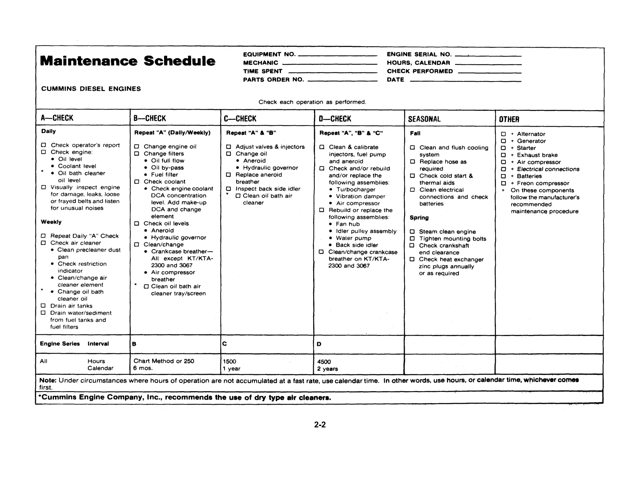
Scheduled Maintenance
Schedule I, Schedule II
The following maintenance schedules should be used to
establish maintenance practices for Cummins standby
(GS) or continuous duty (GC) generator sets.
Schedule I is used with standby applications. Many of
these installations are regulated by NFPA and/or local
codes (reference NFPA No. 76A).
Standby rated generator sets are for supplying electric
power in the event of normal utility power failure. No
overload capability is available for this rating. This
rating may be used for continuous service for as long as
the emergency may last. This rating conforms with the
BS 649:1958 overload rating and DIN "B" 6270.
Schedule II is used with continuous duty applications.
Continuous duty rated generator sets are for supplying
electric power in lieu of commercially purchased power.
Intermittent overloads up to the standby rating are
allowable. This rating may be used for continuous
service in commercial applications and it conforms with
BS 649:1958 and DIN "A" 6270 for generator set
applications.
Using The Suggested Schedule Check Sheet
Actual operating environment of the engine governs the
maintenance schedule. The-suggested check sheet on
the following page indicates some checks have to be
performed more often under heavy dust or other special
conditions.
The maintenance schedule check sheet is designed as a
guide until adequate experience is obtained to establish
a schedule to meet a specific operation.
A detailed list of component checks is provided through
several check periods; also a suggested schedule basis
is given for hours of operation, or calendar of time.
A maintenance schedule should be established using
the check sheet as a guide; the result will be a
maintenance program to fit a specific operation.
Cummins Standby Generator Sets
Cummins standby generator sets may be required to
start and come on line in 10 seconds or less.
These engines must be equipped with engine coolant
heaters capable of maintaining coolant temperature at a
minimum of 100°F [38° C].
Engines subject to ambient temperatures less than 2-4
70° F [21° C] must also be equipped with a lubricating
oil heater. When using a lubricating oil heater
immersed in oil, the maximum surface of heater in
contact with oil, should be less than 300° F [149° C] to
minimize formation of hard carbon on the heating
element.
Recommended wattage for the heaters when the unit is
in a protected area or in an enclosure are shown in
Bulletin No. 3379009, in Section 7 Miscellaneous.
Standby units should be operated once a week under a
minimum of 25% of rated KW load for at least thirty
minutes. During this test, the engine must reach normal
operating temperature.
Cummins Continuous Duty Generator Sets
Continuous duty generator sets may be equipped with a
cold starting aid. Maintenance procedures for these
devices can be found in the seasonal maintenance
section.
2-4](https://image.slidesharecdn.com/megafileuploadnta855workshopmanaul-141014164750-conversion-gate01/75/work-shop-manaul-CUMMINS-MODEL-NTA-855-L4-23-2048.jpg)


![Operation and Maintenance
Construction and Industrial
Table 2-1: Belt Tension (Lbs.)
Belt New Belt* Minimum • Used Belt Installation Tension
Width Belt Tension Tension • If Below Min. Tension, Retention to
Inches Gauge (lb.) + 10 (lb.) (lb.) + 10
.380 ST-12748 140-150 60 100
.440 CAN-292 140-150 60 100
1/2 140-150 60 100
11/16 160-170 60 100
3/4 ST-1138 160-170 60 100
7/8 160-170 60 100
K-Sect.
5 Rib ST-1293 125-135 60 100
V-Ribbed
K-Sect
6, Rib- ST-1293 150-160 70 120
V-Ribbed
K;Sect
10 Rib NUA 250-260 140 200
V-Ribbed
* Used belts should be retensioned to values listed in this column.
Note: A belt is considered as used. if it has been in operation for a period of time of at least 5 minutes.
and/or adjust belts to the tension as indicated in Table 2-
1.
Fig. 2-3, (OM1015L). Adjusting belt tension with ST-
1293
Note: When using the "Krikit" gauge the correct belt
tension reading for the belt tested must be read at the
point where the top of the black indicator arm crosses
the bottom numbered scale. Position the gauge in the
center of the belt between two pulleys. The flange at
the side of the gauge should be flat against the edge of
the belt.
Inline Engine Water Pump Belts (No Idler)
1. Eccentric water pump adjustment.
a. Loosen the water pump clamp ring to allow the
pump body to turn.
b. Loosen the pump body by pulling up on the
belts. A sharp jerk may be required.
c. Insert a bar in the water pump body slots and
rotate the pump body counterclockwise to
tighten the belts.
Note: Do not adjust to final tension at this time.
d. Snug the clamp ring capscrew farthest from the
belts, on the exhaust side to 5 ft-lbs [7 N m].
e. Snug the two capscrews above and below the
first one to 5 ft-lbs [7 N m].
f. Finish tightening by alternating from side to side
in 5 ft-lbs [7 N.m] increments to a final torque of
12 to 15 ft-lbs [16 to 20 N m].
2-8](https://image.slidesharecdn.com/megafileuploadnta855workshopmanaul-141014164750-conversion-gate01/75/work-shop-manaul-CUMMINS-MODEL-NTA-855-L4-27-2048.jpg)
![Maintenance Instructions
g. Check the belt tension.
Final belt tension was not obtained by adjustment alone.
The water pump body was pulled straight by snugging
the capscrews in the order described, thus increasing
the belt tension to the final value.
2. Adjustable (split) pulley water pumps, V-903
Engines only.
a. Remove the capscrews joining the sheave(s) of
the pulley.
Note: Clean the capscrew threads and holes in the
sheaves thoroughly to avoid capscrew breakage during
reassembly.
b. The outer half of the pulley is screwed onto the
hub extension of the inner half. Some pulleys
are provided with flats, and some with lugs for
barring.
c. Bar the engine over to roll the belt outward on
the pulley as the outer half is turned in.
d. Adjust the belt(s) to the tension indicated in
Table 2-1.
e. Turn the outer sheave(s) in enough to align the
capscrew holes.
f. Start the capscrews and tighten alternately and
evenly. Final tension is: 5/16-18 capscrew, 10
to 12 ft-lbs [14 to 16 N•m] 3/8-16 capscrew, 17
to 19 ft-lbs [23 to 26 N om] g. Bar the engine
over one or two revolutions to seat the belt.
h. Recheck the belt tension.
Fig. 2-4, (N11974). Water pump with idler
Inline Engine Water Pump Belts (With Idler)
1. Loosen the capscrews and lockwashers or locknut
securing the idler pulley to the bracket or water
pump. Fig. 2-4.
2. Using a pry bar (NTA) or adjusting screw (FFC)
adjust the idler pulley until the proper belt tension is
indicated on the gauge. See Table 2-1.
3. Secure the idler pulley or bracket in position by
tightening the locknut or capscrews and lockwashers
to 45 to 55 ft-lbs [61 to 75 N m] torque.
Note: The self tensioning idler on V-1710 belt driven
water pumps requires no adjustment or belt tension
check.
Fan Drive Belts
1. Loosen the large locking nut on the fan hub shaft or
the capscrews securing the fan hub shaft to the
mounting bracket. The fan hub will fall out of line
when this is done.
2. Turn the adjusting screw to increase the belt
tension.
3. Tighten the locknut or capscrews until the fan hub is
straight. Snug the nut to maintain the hub in proper
alignment with the fan hub bracket.
Caution: Do not adjust to full tension with the
adjusting screw, as this would result in
overtightening.
4. Belt tension should read as indicated in Table 2-1 on
applicable gauge.
5. Tighten NH/NT Engines locknut to 400 to 450 ft-lbs
[542 to 610 N m]; then back off 1/2 turn. Tighten
the four 1/2 inch capscrews, Fig. 2-5, on NTC-350
FFC Engines to 75 to 85 ft-lbs [101 to 115 N.m].
On V-903 Engines tighten capscrews to 75 ft-lbs [102
N.m] or single nut to 450 ft-lbs [610 N.m].
6. Recheck the belt tension.
7. Back out the adjusting screw one-half turn to
prevent breakage.
Note: The self tensioning backside idler on KT/KTA2300
and KTA-3067 belt driven fan requires no belt tension
check.
Generator/Alternator Belts
Belt tension should be as indicated in Table 2-1 when
measured with the applicable gauge.
2-9](https://image.slidesharecdn.com/megafileuploadnta855workshopmanaul-141014164750-conversion-gate01/75/work-shop-manaul-CUMMINS-MODEL-NTA-855-L4-28-2048.jpg)
![Operation and Maintenance
Construction and Industrial
Fig. 2-5, (OM10161). Fan hub installation, NT-350 FFC
Belt Installation.
If the belts show wear or fraying, replace as follows:
1. Always shorten the distance between the pulley
centers so the belt can be installed without force.
Never roll a belt over the pulley and never pry it on with
a tool such as a screwdriver. Either of these methods
will damage the belts and cause early failure.
2. Always replace the belts in complete sets. Belts
riding depth should not vary over 1/16 in [1.6 mm]
on matched belt sets.
3. Pulley misalignment must not exceed 1/16 in 11.
6 mm] for each ft 10.3 m] of distance between
the pulley centers.
4. Belts should not bottom on the pulley grooves nor
should they protrude over 3/32 in [2.4 mm] above
the top edge of the groove.
5. Do not allow belts to rub any adjacent parts 6.
Adjust belts to the proper tension.
Readjusting New Belts.
All new belts will loosen after running for 5 minutes and
must be readjusted to "belt tension after run-in" Ref.
Table 2-1.
Check Oil Bath Cleaner Oil Level.
Daily check oil level, Fig. 2-6, in the oil bath air cleaner
to be sure the oil level in the cup is at the indicated
mark. Refill as required.
*Cummins Engine Company, Inc. recommends the use
of dry type air cleaners.
Check for Damage.
Visually check the fuel system, etc., for misadjustment
or tampering; check all connections for leaks or
damage. Check the engine for damage; correct as
necessary.
Fig. 2-6, (Nl1001). Checking oil level in air cleaner
2-10](https://image.slidesharecdn.com/megafileuploadnta855workshopmanaul-141014164750-conversion-gate01/75/work-shop-manaul-CUMMINS-MODEL-NTA-855-L4-29-2048.jpg)
![Maintenance Instructions
30
"A" Maintenance Checks-Weekly
Repeat Daily Checks
Check Air Cleaner
Clean Pre-Cleaner and Dust Pan
Under extremely dirty conditions an air pre-cleaner may
be used. Clean the pre-cleaner jar and dry-type air
cleaner dust pans daily or more often, as necessary,
depending on operating conditions.
Check Inlet Air Restriction
Mechanical Indicator
A mechanical restriction indicator is available to indicate
excessive air restriction through a dry-type air cleaner.
This instrument can be mounted in the air cleaner outlet
or on the vehicle instrument panel. The red flag (1, Fig.
2-7) in the window gradually rises as the cartridge loads
with dirt. After changing or replacing the cartridge, reset
the indicator by pushing the reset button (2).
Fig 2-7, (CGS-20). Air inlet restriction indicator
Note: Never remove the felt washer from the indicator.
It is necessary to absorb moisture.
Vacuum Indicator
Vacuum switches, Fig. 2-8, are available which actuate
a warning light on the instrument panel when the air
restriction becomes excessive.
Fig. 2-8, (N21905). Vacuum switch to check air inlet
1. Air restriction on turbocharged engines must not
exceed 25 inches [635 mm] of water or 1.8 inches [46
mm] of mercury under full power conditions.
2. Naturally aspirated engine air restriction must not
exceed 20 inches [508 mm] of water or 1.5 inches [38
mm] of mercury at air intake manifold at rated speed.
Clean or Replace Air Cleaner Elements
The paper element in a dry-type air cleaner, Fig's. 2-9,
2-10, 2-11 and 2-12, may be cleaned several times by
using air to blow off dirt or by washing with nonsudsing
household detergent and water at 120 to 1400F [49 to
600C], then drying with compressed air, approximately
30 psi [306 kPa]. Do not hold the air jet too close to the
paper element.
Elements that have been cleaned several times will
finally clog and air flow to the engine will be restricted.
After cleaning, check the restriction as previously
described and replace the element if necessary.
Caution: Holes, loose end seals, dented sealing
surfaces and other forms of damage render the
cleaner inoperative and require immediate element
replacement.
To change the element:
1. Loosen the wing nut (1, Fig. 2-9) securing the
2-11](https://image.slidesharecdn.com/megafileuploadnta855workshopmanaul-141014164750-conversion-gate01/75/work-shop-manaul-CUMMINS-MODEL-NTA-855-L4-30-2048.jpg)

![Maintenance Instructions
32
3. Remove the gasket (5) from the outlet end (7) of
he housing.
When installing the element, make sure it seats on the
gasket at the air cleaner outlet end.
Heavy Duty Dry-Type Air Cleaners
Heavy duty air cleaners (single and dual types) combine
centrifugal cleaning with element filtering, Fig's. 2-11
and 2-12, before air enters the engines.
Before disassembly, wipe dirt from the cover and the
upper portion of the air cleaner. To clean single or dual
types:
1. Loosen the wing bolt, remove the band securing
the dust pan (1, Fig. 2-11), (2, Fig. 2-12).
2. Loosen the wing nut (2, Fig. 2-11 and 3, Fig. 2-
12), remove the dust shield (3, Fig. 2-11), (4,
Fig. 2-12), from the dust pan (1, Fig. 2-11), (2,
Fig. 2-12), clean the dust pan and shield.
3. Remove the wing nut (2, Fig. 2-11), (5, Fig. 2-
12) securing the air cleaner primary element (6,
Fig. 2-12) in the air cleaner housing, inspect the
rubber sealing washer on the wing nut (4, Fig.
2-11), (5, Fig. 2-12).
4. Blow out the element from the clean air side
with compessed air not exceeding 30 psi [207
kPa].
5. Wash the element with nonsudsing household
detergent and water, 120 to 140° F [49 to 60°
C]. Dry with compressed air, 30 psi [207 kPa].
6. Inspect the element after cleaning.
7. Install a new or the cleaned primary element.
8. Be sure the gasket washer is in place under the
wing nut before tightening.
9. Reassemble the dust shield and dust pan,
position them to the air cleaner housing and
secure with the band.
10. On the dual element type Cyclopac cleaner:
a. Check the air restriction indicator. If the air
restriction is excessive, disassemble the
air cleaner, remove the wing nut (8, Fig.
2-12), and replace the safety element
(9).
b. Reassemble the air cleaner as described in
"Steps 8 and 9" above. Cartridge Type
Air Cleaner Element
1. Loosen the wing nuts (4, Fig. 2-13or2-14) on
the air cleaner housing (5) to remove the pre-cleaner
Fig 2-13. (N21026). Air cleaner - cartridge type (two
stage)
Fig. 2-14, (V11009). Air cleaner- cartridge type (single
stage)
panel with the dust bin (1). To remove the pre-cleaner
panel (2) equipped with an exhaust
aspirator loosen the "U" bolt clamp securing
the pre-cleaner to the aspirator tubing.
2. Remove the dirty Pamic cartridge (3), by
inserting your fingers in the cartridge opening
(loosen all four corners of the cartridge, one at
a time) and pulling it straight out.
With the larger cartridge, it may be necessary to break
the seal along the edges of the cartridge. After the seal
has been broken, pull the cartridge straight out and
slightly up so the cartridge will clear the sealing frame
and edges of the air cleaner housing.
Cleaning and Inspection
1. Clean the pre-cleaner openings (2) of all soot,
oil film and any other objects that may have
become lodged in the openings. Remove any
dust or dirt in
2-13](https://image.slidesharecdn.com/megafileuploadnta855workshopmanaul-141014164750-conversion-gate01/75/work-shop-manaul-CUMMINS-MODEL-NTA-855-L4-32-2048.jpg)
![33
Operation and Maintenance
Construction and Industrial
the lower portion of the pre-cleaner and aspirator
tubing. Inspect the inside of the air cleaner
housing for foreign material.
2. Inspect the dirty cartridge for soot or oil. If there is
soot inside the Pamic tubes, check for leaks in the
engine exhaust system, exhaust "blow-back" into
the air intake and exhaust from other equipment. If
the cartridge appears "oily", check for fumes
escaping from the crankcase breather. Excessive
oil mist shortens the life of any dry-type cartridge.
Troubleshooting at this point can appreciably
lengthen new cartridge life.
3. It is not recommended to clean and reuse the
cartridge. When returned to service, life
expectancy of a paper cartridge will be only a
fraction of the original service life.
4. Inspect clamps and flexible hose or tubing to be
sure all fittings are air tight on cleaners with
exhaust aspirators.
5. The pre-cleaner dust bin is self-cleaning.
Assembly
1. Inspect the new filter cartridge for shipping damage
before installing.
2. To install a new cartridge, hold the cartridge (3,
Fig. 2-13 and 2-14) in the same manner as when
removing it from the housing. Insert the clean
cartridge into the housing; avoid hitting the
cartridge tubes against the sealing flange on the
edges of the air cleaner housing.
3. The cleaner requires no separate gaskets for seals;
therefore, care must be taken inserting cartridge to
insure a proper seat within the cleaner housing.
Firmly press all edges and corners of the cartridge
with your fingers to effect a positive air seal against
the sealing flange of the housing. Under no
circumstances should the cartridge be pounded or
pressed in the center to effect a seal.
4. Replace the pre-cleaner panel (2) and tighten the
wing nuts (4) by hand, for final tighteness turn 1-1/2
to 2 turns with a small adjustable wrench. Do not
overtighten. On a pre-cleaner with an exhaust
aspirator, assemble the aspirator tube to the pre-cleaner
panel and tighten the "U" bolt.
5. Care should be taken to keep the cleaner face
unobstructed.
Change Oil Bath Air Cleaner Oil
Before dirt build-up reaches 1/2 inch [12.7 mm], remove
the oil cup from the cleaner. Discard the oil
and wash the cup in cleaning solvent or fuel oil.
Note: During wet weather and in winter months,
changing of the oil is equally as important as during
dusty weather since the air cleaner inlet may be located
in an air stream which carries moisture into the cleaner.
Fill the oil cup to the level indicated by the bead on the
side with clean, fresh oil of the same grade as that in the
crankcase and assemble it to the cleaner. In extremely
cold weather a lighter grade may be necessary. A
straight mineral, non-foaming detergent, or non-foaming
additive oil may be used in oil bath air cleaners.
Caution: Never use dirty oil or used oil.
Drain Air Tanks
In cold weather, condensed moisture in the air tanks and
lines may freeze and make controls useless. Drain the
air tanks to keep all water out of the compressed air
system.
Drain Sediment from Fuel Tanks
Loosen the fuel tank drain cock or plug, if used, and
drain approximately 1 cup of fuel to remove water and
sediment. Close the drain cock or plug.
Fuel/Water Filter Separator
If more moisture than usual is present when checking
the fuel tanks, it may be advisable to install a water
separator.
Contact the nearest Cummins Dealer for a Fleetguard
water separator that meets requirements.
Drain plugs are located in the bottom of some fuel filter
cases and in the sump of some fuel supply tanks. More
condensation of water vapor occurs in a partially filled
fuel tank than in a full one. Therefore, fuel supply tanks
should be kept as nearly full as possible. Warm
returning fuel from the injectors heats the fuel in the
supply tank. If the fuel level is low in cold weather, the
fact that the upper portion of the tank is not being
heated by returning fuel tends to increase condensation.
In warm weather both the supply tank and the fuel are
warm. In the night, however, cool air lowers the
temperature of the tank much more rapidly than the
temperature of the fuel. Again this tends to increase
condensation.
Engine Front Trunnion
If used, the engine front trunnion mount should be
lubricated with grease meeting specifications as outlined
in Section 3.
2-14](https://image.slidesharecdn.com/megafileuploadnta855workshopmanaul-141014164750-conversion-gate01/75/work-shop-manaul-CUMMINS-MODEL-NTA-855-L4-33-2048.jpg)


![Maintenance Instructions
46
commercial used oil analysis laboratories. These
analyses are not low cost, generally costing between
$50 and $135 per sample.
When any one of the condemnation limits is exceeded
on any one sample an oil change should be performed
on all engines in the sub-group. The hours at which the
sample for which a condemnation limit was exceeded is
the oil change interval at which 10% or more (depending
on sub-group size) of the group are using lubricating oil
which has exceeded its useful life. This sampling and
analysis process should be repeated once to confirm the
oil change interval. When this process is complete the
entire group of engines can be placed on the new oil
change interval.
This method of establishing an oil change interval will
determine a different interval for each group of engines.
It is not possible to provide maintenance on several
different schedules or if one desires to schedule the oil
change to coincide with other maintenance, the more
conservative (or shorter) maintenance schedule should
be used.
Please contact your Cummins Service Representative if
you need assistance or have any questions about
utilizing this method of determining an oil change
interval.
Change Engine Oil
Factors to be checked and limits for oil analysis are
listed below. Oil change at "B" Check, as shown in the
maintenance chart on Page 2-2, is for average
conditions.
1. Bring engine to operating temperature, shut down
engine, remove drain plug from bottom of oil pan,
and drain oil.
2. Install drain plug in oil pan. On 855, V-903, KT(A)-
1150, KT(A)-2300 and KT(A)-3067 engines torque to
60 to 70 ft-lbs [81 to 95 N•m]. On V-378, V-504 and
V-555 engines torque to 35 to 40 ft-lbs [47 to 54
N•m]. On V-1710 engines torque to 45 to 55 ft-lbs
[61 to 75 N•m].
3. Fill the crankcase to "H" (high level) mark on the
dipstick.
4. Start engine and visually check for oil leaks.
5. Shut down the engine; allow 15 minutes for oil to
drain back into the pan; recheck the oil level with
the dipstick. Add oil, as required.
Note: Use lubricating oil meeting specifications listed in
Section 3, and genuine Cummins filters on equipment.
Change Spin-On Lubricating Oil Filter Elements
1. Unscrew combination case and elements, Fig. 2-15,
discard elements.
Fig. 2-15, (OM1018L). Installing lubricating oil filter
cartridge
Note: At each filter change check torque of adapter
mounting capscrew; it should be 25 to 35 ft-lbs [34 to 47
N•m]. If the capscrew is not within torque range, the
adapter may rotate when the spin-on filter is removed.
Replace the adapter to the filter head gaskets at each
"C" maintenance check.
2. Fill the filter with lubricating oil. Apply a light even
coat of lubricating oil to the gasket sealing surface prior
to installing the filter.
Fig. 2-16, (K21907). Installing "spin-on" lubricating
oil filter - KT(A)-2300 Engine
2-27](https://image.slidesharecdn.com/megafileuploadnta855workshopmanaul-141014164750-conversion-gate01/75/work-shop-manaul-CUMMINS-MODEL-NTA-855-L4-46-2048.jpg)

![Maintenance Instructions
48
Caution: Never use a by-pass filter in place of a full-flow
filter.
Change Fuel Filter Element
Spin-On Type Filter
1. Unscrew the combination case and element, Fig. 2-
19, discard the element.
2. Fill the new filter with clean fuel and apply a light
even coat of lubricating oil to the gasket sealing
surface prior to installing the filter.
3. Install the filter; tighten by hand until the seal
touches the filter head. Tighten an additional one-half
to three-fourths turn.
Fig. 2-19, (Vl1909). Changing "spin-on" type fuel filter
Caution: Mechanical tightening will distort or crack
the filter head.
Fig. 2-20, (OM1021L). Installing replaceable
fuel filter element
Replaceable Element
1. Open the drain cock(s) and drain the contents.
2. Loosen the nut(s) at the top of the fuel filter(s).
Take out the dirty element, clean the filter case(s)
and install new element(s). Fig. 2-20.
3. Install new gasket(s) in the filter(s) and assemble
the case(s) and element(s). Tighten center bolt(s) to
20 to 25 ft-lbs [27 to 34 N•m] with a torque wrench.
Fill the filter case(s) with clean fuel to aid in faster
pick-up of fuel.
4. Check the fittings in the filter head(s) for leaks.
Fittings should be tightened to 30 to 40 ft-lbs [41 to
54 N•m].
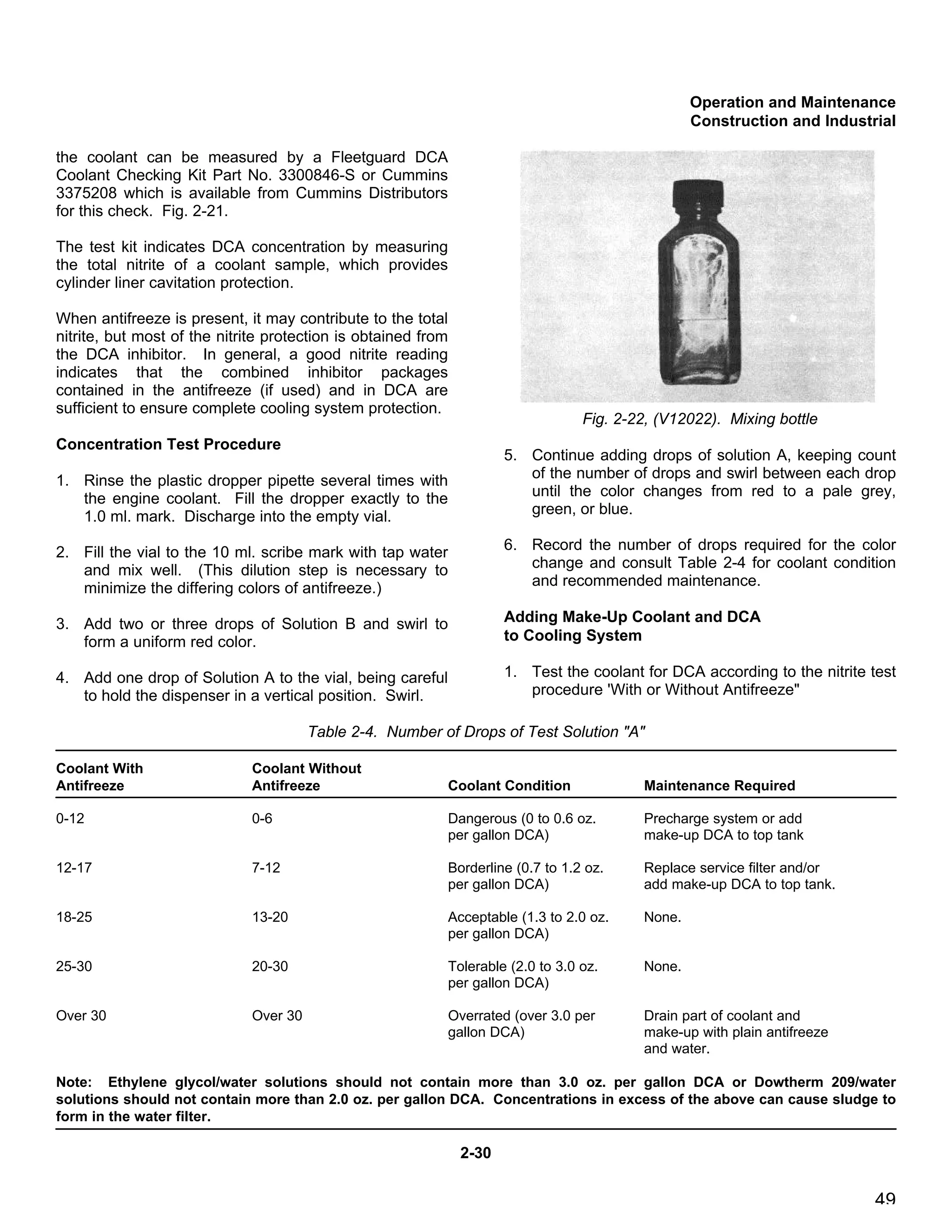
Check Engine Coolant
Periodic tests of the engine coolant should be made to
ensure that the frequency of water filter servicing or
concentration of DCA inhibitor is adequate to control
corrosion for any specific condition of operation. In
cases where "make-up" water must be added frequently,
we suggest that a supply of water be treated and added
as necessary.
The concentration of effective inhibitor dissolved in
Fig. 2-21, (N12021). DCA coolant test kit
2-29](https://image.slidesharecdn.com/megafileuploadnta855workshopmanaul-141014164750-conversion-gate01/75/work-shop-manaul-CUMMINS-MODEL-NTA-855-L4-48-2048.jpg)
![Maintenance Instructions
50
depending on the presence or absence of antifreeze
in the cooling system.
2. Estimate the make-up DCA. For example, if a
fifteen gallon cooling system contains only 0.5
oz/gal. [4 ml per I] DCA, and 1.5 oz/gal. [12 ml per
I] is required, 15 ounces [426 g] of DCA should be
added to the make-up coolant.
Note: A one pint bottle of DCA-4L liquid (P/N 3300858)
contains six dry ounces of DCA chemical in Step 2,
concentrations are in dry ounces of chemical per gallon
of coolant.
3. Estimate the total amount of make-up coolant
required (gallons), and calculate the proportions of
water and antifreeze, if used, required. For
example, one gallon of 50-50 antifreeze/water
solution will require two quarts of antifreeze and two
quarts of water.
4. Add the required amount of water to a mixing
container and dissolve the number of ounces of
DCA obtained in Step 2 in the water. If negative or
zero results were obtained in Step 2, do not add
DCA. (For DCA to dissolve, water should be above
50°F [10°C].)
5. Add the required amount of antifreeze, if used, to
the water solution and mix thoroughly.
6. Add the make-up coolant to the cooling system.
Note: If the DCA concentration is low, and the coolant
level high, DCA may be added directly to the radiator in
the amount indicated in Step 2. The engine should be
running and warm enough to permit coolant circulation
throughout the entire system.
Bulk Storage of Make-Up Coolant
If make-up coolant is stored in bulk, the following
recommendations are provided for mixing and storing
the coolant.
1. Drain and clean the bulk storage tank to remove any
possible contaminants.
2. Knowing the total capacity of the holding tank,
calculate the proportions of water and antifreeze, if
used, required. For example, a 500 gallon [1892 l]
tank will hold 250 gallons [946 I] of water and 250
gallons [946 l] of antifreeze for a 50-50 mixture.
3. Multiply the desired DCA concentration by the total
capacity of the holding tank in gallons. In the
example above, 1.5 oz. DCA per gallon [12 ml per I]
of coolant can be used in the 50-50 mixture.
Multiplying 1.5 oz. DCA per gallon [12 ml per I]
times 500 gallons [1892 l] yields a total DCA
requirement of 750 oz. [46 lb. 14 oz.] [21.3 kg].
4. Add the water to the holding tank. Agitating
continuously, add the DCA to the water in small
amounts until all of the chemical has dissolved. The
water should be above 50°F [10°C].
5. Add the antifreeze last, if used, maintaining
agitation to bring and keep the finished coolant in
solution. Both antifreeze and DCA will settle to the
bottom of the tank unless constant mixing or
recirculation is provided. An example of
recirculation is the use of a small pump operating
continuously to draw DCA and antifreeze off the
bottom of the tank and discharging the solution at
the top. Samples of coolant can be drawn off the
top, middle and bottom of the storage tank and
tested for antifreeze and/or DCA concentration if
inadequate mixing is suspected.
Change DCA Water Filter
Change the filter or element at each "B" Check;
selection of element to be used should be based upon
the size of the system. See "Coolant Specifications",
Section 3.
Note: Whenever the coolant supply is changed the
system must be drained, flushed, and precharged. See
"Coolant Specifications", Section 3 for DCA
compatibility with different brands of antifreeze.
Spin-On Element
1. Close the shut-off valves on inlet and drain lines.
2. Unscrew the element and discard.
3. Apply a light even coat of lubricating oil to the
Fig. 2-23, (OM1023L). Installing DCA water filter
cartridge
2-31](https://image.slidesharecdn.com/megafileuploadnta855workshopmanaul-141014164750-conversion-gate01/75/work-shop-manaul-CUMMINS-MODEL-NTA-855-L4-50-2048.jpg)


![Operation and Maintenance
Construction and Industrial
53
"C" Maintenance Checks
At each "C" Maintenance Check, first perform all "A"
and "B" Checks in addition to those following:
Adjust Injectors and Valves
It is essential that the injectors and valves be in correct
adjustment at all times for the engine to operate
properly. One controls engine breathing; the other
controls fuel delivery to the cylinders.
Final operating adjustments must be made using correct
values as stated.
Caution: Be sure the injector and valve set
markings, wherever located, are in proper alignment
with the indicator mark.
Engine Temperatures
The following temperature conditions provide the
necessary stabilization of engine components to allow
for an accurate valve and injector adjustment.
Cummins Engine Company, Inc. recommends that
valve and injector plunger adjustments be made when
the engine is cold. The engine must be at any stabilized
temperature of 140°F [60°C] or below.
A second setting or resetting after the engine is warm is
not recommended.
Injector Plunger Adjustment Using Torque Method,
V/VT-378, V/VT-504, V/VT-555 Engines
The injectors and valves must be in correct adjustment
at all times for the engine to operate properly. This
controls engine breathing and fuel delivery to the
cylinders. Final adjustment must be made when the
engine is at operating temperature. The injectors must
always be adjusted before the valves. The procedure is
as follows:
Valve Set Mark Alignment
1. Turn the crankshaft in direction of rotation until No.
1 "VS" mark appears on the vibration damper or
crankshaft pulley. See Fig. 2-28 for the location of
the valve set marks. In this position, both intake
and exhaust valves must be closed for cylinder No.
1; if not, advance the crankshaft one revolution.
See Fig. 2-29, Fig. 2-30 and Table 2-5 for firing
order.
Fig. 2-28, (OM1035L). Valve set marks -
V/VT-555 C.I.D. Engine
Fig. 2-29, (V11461). V6 firing order
2-34](https://image.slidesharecdn.com/megafileuploadnta855workshopmanaul-141014164750-conversion-gate01/75/work-shop-manaul-CUMMINS-MODEL-NTA-855-L4-53-2048.jpg)
![Maintenance Instructions
54
Fig 2-30, (V11462). V8 firing order
Note: Do not use the fan to rotate the engine.
2. Adjust the injector plunger, then the crossheads and
valves of the first cylinder as explained in
succeeding paragraphs. Turn the crankshaft in the
direction of rotation to the next "VS" mark
corresponding to the firing order of the engine and
the corresponding cylinder will be ready for
adjustment. See Table 2-5.
3. Continue turning the crankshaft in the direction of
rotation and making adjustments until all injectors
and valves have been correctly adjusted.
Table 2-5. Engine Firing Order V Engines
Right Hand V8 1-5-4-8-6-3-7-2
Right Hand V6 1-4-2-5-3-6
Note: Two complete revolutions of the crankshaft are
needed to set all injector plungers and valves. The
injector and valves can be adjusted for only one cylinder
at any one "VS" setting.
Injector Plunger Adjustment
Before adjusting the injector, tighten the injector
holddown capscrew to 30 to 35 ft-lbs [41 to 47 N•m].
The injector plungers of all engines must be adjusted
with an in-lb torque wrench to a definite torque setting.
Snap-On Model TQ12B or equivalent torque wrench and
a screwdriver adapter can be used for this adjustment.
Fig. 2-31.
1. Turn the adjusting screw down until the plunger
contacts the cup and advance an additional 15
degrees to squeeze the oil from the cup.
Fig. 2-31, (OM1037L). Adjusting injector plunger
2. Loosen the adjusting screw one turn. Using a torque
wrench calibrated in in-lbs and a screwdriver adapter,
tighten the adjusting screw to the values shown in Table
2-6 for cold setting and tighten the locknut.
Table 2-6. Injector Plunger Adjustment Torque
V/VT-378, V/VT-504, V/VT-555 Engines
Oil Temperature Oil Temperature
Cold Hot
60 in-lbs [6.8 N•m] 60 in-lbs [6.8 N•m]
Fig 2-32 (OM1038L). Tighten injector adjusting screw
locknut
3-35](https://image.slidesharecdn.com/megafileuploadnta855workshopmanaul-141014164750-conversion-gate01/75/work-shop-manaul-CUMMINS-MODEL-NTA-855-L4-54-2048.jpg)
![Operation and Maintenance
Construction and Industrial
55
Note: After all the injectors and valves are adjusted
and the engine has been started and warmed up to
140°F [69°C] oil temperature, reset the injectors to the
warm setting. This is only necessary if the injectors,
lever assemblies, or push rods have been changed.
3. Hold the injector adjusting screw and tighten the
injector adjusting screw locknut to the values
indicated in Table 2-7.
When an ST-669 Adapter is used, nut torque is reduced
to compensate for additional torque arm length. Fig. 2-
32.
Table 2-7. Injector and Valve Locknut Torque
V/VT-378, V/VT-504, V/VT-555 Engines
Without ST-669 With ST-669
40 to 45 ft-lbs. 30 to 35 ft-lbs.
[54 to 61 N•m] [41 to 47 N•m]
Crosshead Adjustment
Crossheads are used to operate two valves with one
rocker lever. The crosshead adjustment is provided to
assure equal operation of each pair of valves and
prevent strain from misalignment.
1. Loosen the valve crosshead adjusting screw locknut
and back off the screw one turn.
2. Use light finger pressure at the rocker lever contact
surface to hold the crosshead in contact with the
valve stem (without the adjusting screw).
Fig. 2-33, (UM1039L). Adjusting crossheads
3. Turn down the crosshead adjusting screw until tit
touches the valve stem. Fig. 2-33.
4. Hold the adjusting screw in this position and torque
the locknut to the values listed in Table 2-8.
5. Check the clearance between the crosshead and the
valve spring retainer with a wire gauge. There must
be a minimum of 0.025 inch [0.64 mm] clearance at
this point.
Valve Adjustment
The same crankshaft position used in adjusting the
injectors is used for setting the intake and exhaust
valves.
Table 2-8. Crosshead Locknut Torque
Without ST-669 With ST-669
25 to 30 ft-lbs. 22 to 26 ft-lbs.
[34 to 41 N•m] [30 to 35 N•m]
1. Loosen the locknut and back off the adjusting screw.
Insert a feeler gauge between the rocker lever and
the top of the crosshead. Valve clearances are
shown in Table 2-9. Turn the screw down until the
lever just touches the gauge and lock the adjusting
screw in this position with the locknut. Fig. 2-34.
Torque the locknut to the values indicated in Table
2-7; note Step 2 under "Injector Plunger
Adjustment".
Table 2-9: Valve Clearances - Inch [mm]
V/VT-378, V/VT-504, V/VT-555 Engines
Intake Valve Exhaust Valve
Oil Temperature Oil Temperature
Cold Cold
0.012 0.022
[0.30] [0.56]
V-903 Engines Injector Adjustment,
Using Dial Indicator Method
This method involves adjusting the injector plunger
2-36](https://image.slidesharecdn.com/megafileuploadnta855workshopmanaul-141014164750-conversion-gate01/75/work-shop-manaul-CUMMINS-MODEL-NTA-855-L4-55-2048.jpg)
![Maintenance Instructions
56
Fig. 2-34, (OM1040L). Adjusting valves
travel with an accurate dial indicator rather than
tightening the adjusting screw to a specified torque.
The "indicator method" eliminates errors in adjustment
caused by friction in the screw threads and distortion
from overtightening the adjusting screw locknut. A
check can be made of the adjustment without disturbing
the locknut or screw setting. The valves can also be
checked or set while adjusting the injectors by this
method. See Table 2-10 for specifications.
Table 2-10. Adjustment Limits Using Dial
Indicator Method Inch [mm] V-903 Engines
Injector Plunger Valve Clearance
Travel Intake Exhaust
1 to 1 Rocker Lever Ratio - Injector Lever P/N 211319
0.187 ± 0.001 0.012 0.025
[4.75 ± 0.03] [0.30] [0.64]
Before adjustment, tighten the injector hold-down
capscrew to 30 to 35 ft-lbs [41 to 47 N•m] torque.
Note: Remove the key, and using either a 3/8 inch hex
drive for female type barring device or a 5/8 inch six-point
socket for the male type barring device, press
inward until the barring gear engages the drive gear;
then advance. Fig. 2-35. After completion of
adjustment, be sure the drive retracts and install the key
into the safety lock groove.
Using the regular engine barring device, Fig. 2-35,
rotate the engine in the direction of rotation with the
"VS" mark for cylinder 2-8 is aligned with the pointer. In
this position both the intake and exhaust valve rocker
levers for No. 2 cylinder should be free and can be
moved up and down. If not, bar the engine another 360
degrees in the direction of rotation and realign the 2-8
"VS" mark.
Fig. 2-35, (OM1041L). Barring V-903 Engine
The timing mark locations (Figs. 2-36 and 2-37) are
used with the dial indicator method of setting the
injectors and valves. Alignment, in either location,
should be held to within one-half inch [12.7 mm] of the
pointer.
Fig 2-36, (OM1042L). Location of timing marks on front
cover and vibration damper
Note: No. 2 cylinder is selected for the purpose of
illustration only. Any other cylinder could be used, if so
desired.
2-37](https://image.slidesharecdn.com/megafileuploadnta855workshopmanaul-141014164750-conversion-gate01/75/work-shop-manaul-CUMMINS-MODEL-NTA-855-L4-56-2048.jpg)
![Operation and Maintenance
Construction and Industrial
57
Fig. 2-37, (V514127). Valve set mark on
accessory drive - V-903
1. Set up the ST-1270 Indicator Support with the
indicator extension atop the injector plunger flange
at No. 2 cylinder, Fig. 2-38.
Fig. 2-38, (V514114). Dial indicator in place - V-903
2. Screw the injector lever adjusting screw down until
the plunger is bottomed in the cup, back off
approximately 1/2 turn then bottom again, set the
dial indicator at zero (0).
Note: Care must be taken to assure the injector plunger
is correctly bottomed in the cup, without overtightening
the adjusting screw, before setting the dial indicator.
3. Back the adjusting screw out until a reading of 0.187
inch [4.75 mm], reference Table 2-10, is obtained on
the dial indicator. Snug tighten the locknut.
4. Using ST-1251 Rocker Lever Actuator, bottom the
injector plunger, check the zero (0) setting. Fig. 2-
39. Allow the plunger to rise slowly, the indicator
must show the plunger travel to be within the range
specified in Table 2-10.
Fig 2-39, (V514128). Bottoming injector plunger
in cup - V-903
5. Using ST-669 Torque Wrench Adapter to hold the
adjusting screw in position, torque the locknut 30 to
35 ft-lbs [41 to 47 N•m]. If the torque wrench
adapter is not used, hold the adjusting screw with a
screwdriver, torque the locknuts 40 to 45 ft-lbs [54 to
61 N•m].
6. Actuate the injector plunger several times as a
check of the adjustment. Remove the dial indicator
assembly.
7. Adjust the valves on the appropriate cylinder as
determined in Step 1 and Table 2-10. Tighten the
locknuts the same as the injector locknut.
Crosshead Adjustment
Crossheads are used to operate two valves with one
rocker lever. The crosshead adjustment is provided to
assure equal operation of each pair of valves and
prevent strain from misalignment.
1. Loosen the valve crosshead adjusting screw locknut
and back off the screw one turn.
2. Use light finger pressure at the rocker lever contact
surface to hold the crosshead in contact with the
valve stem (without adjusting screw). Fig. 2-40.
3. Turn down the crosshead adjusting screw until it
touches the valve stem.
2-38](https://image.slidesharecdn.com/megafileuploadnta855workshopmanaul-141014164750-conversion-gate01/75/work-shop-manaul-CUMMINS-MODEL-NTA-855-L4-57-2048.jpg)
![Maintenance Instructions
58
Fig. 2-40, (V51490). Adjusting crossheads - V-903
4. Hold the adjusting screw in position and torque the
locknut to the values listed in Table 2-8.
Note: Be sure that the crosshead retainer on the
exhaust valves, if used, is positioned equally on both
sides of the spring over the crossheads and valve
springs properly.
5. Check the clearance between the crosshead and the
valve spring retainer with a wire gauge. There must
be a minimum of 0.025 inch [0.64 mm] clearance at
this point.
Valve Adjustment
The same engine position used in adjusting injectors is
used for setting intake and exhaust valves.
1. Loosen the locknut and back off the adjusting screw.
Insert a feeler gauge between the rocker
Fig. 2-41, (V51492). Adjusting valves - V-903
lever and the top of the crosshead. Fig. 2-41.
Valve clearances are shown in Table 2-10. Turn the
screw down until the lever just touches the gauge,
and lock the adjusting screw in position with the
locknut. Torque the adjusting screw locknuts to 40
to 45 ft-lb [54 to 61 N•m] or 30 to 35 ft-lb [41 to 47
N•m] when using an ST-669 Adapter.
2. Always make the final valve adjustment after the
injectors are adjusted.
NH-743, N-855, C.I.D. Engines, Injector and
Valve Adjustment (Dial Indicator Method)
Note: Before adjusting the injectors and valves be sure
to determine if the rocker housings are cast iron or
aluminum and use the appropriate setting.
Before adjusting the injectors, torque the cylindrical
injector, hold-down capscrews in alternate steps to 10 to
12 ft-lbs [14 to 16 N•m]. With flange injectors torque the
hold-down capscrews in alternate steps to 12 to 14 ft-lbs
[14.6 to 18 N•m]. Tighten the fuel inlet and drain
connections to 20 to 25 ft-lbs [27 to 34 N•m] in the
flange injectors.
Maintenance Adjustment
1. Bar the engine until "A" or 1-6 "VS" mark on the
pulley, Fig. 2-42, is aligned with the pointer on the
gear case cover. In this position, both valve rocker
levers for cylinder No. 5 must be free (valves
closed). The injector plunger for cylinder No. 3 must
be at top of its travel; if not, bar the engine 360
degrees, realign the mark with the pointer.
2. Set up ST-1170 Indicator Support with the indicator
extension on the injector plunger top at No. 3
Fig. 2-42, (N114230). Accessory drive pulley marking -
N-855
2-39](https://image.slidesharecdn.com/megafileuploadnta855workshopmanaul-141014164750-conversion-gate01/75/work-shop-manaul-CUMMINS-MODEL-NTA-855-L4-58-2048.jpg)
![59
Fig. 2-43, (OM1051L). Extension in contact with plunger Fig. 2-44, (OM1052L). Actuating rocker lever
cylinder, Fig. 2-43. Make sure the indicator
extension is secure in the indicator stem and not
against the rocker lever.
Note: Cylinder No. 3 for injector setting and cylinder
No. 5 for valve setting are selected for illustration
purposes only. Any cylinder combination may be used
as a starting point. See Table 2-11.
Table 2-11: Injector and Valve Set Position
N-855 Engines
Bar in Pulley Set Cylinder
Direction Position Injector Valve
Start A or 1-6VS 3
5
Adv. To B or 2-5VS 6 3
Adv. To C or 3-4VS 2 6
Adv. To A or 1-6VS 4 2
Adv. To B or 2-5VS 1 4
Adv. To C or 3-4VS 5 1
3. Using ST-1193 Rocker Lever Actuator, Fig. 2-44, or
equivalent, bar the lever toward the injector until the
plunger is bottomed to squeeze the oil film from the
cup. Allow the injector plunger to rise, then bottom
again. Set the indicator at zero (0). Check the
extension contact with the plunger top.
4. Bottom the plunger again, release the lever; the
indicator must show travel as indicated in Table 2-
12. Adjust as necessary.
5. If loosened, tighten the locknut to 40 to 45 ft-lbs [54
to 61 N•m] and actuate the injector plunger several
times as a check of the adjustment. Tighten to 30 to
35 ft-lbs [41 to 47 N•m] when using ST-669 Adapter.
Table 2-12. Adjustment Limits Using Dial Indicator
Method Inch [mm] N-855 Engines
Injector Plunger
Oil Travel Valve Clearance
Temp. Inch [mm] Inch [mm]
Adj. Value Intake Exhaust
Aluminum Rocker Housing
Cold 0.170 0.011 0.023
[4.32] [0.28] [0.58]
Hot 0.170 0.011 0.023
[4.32] [0.28] [0.58]
Cast Iron Rocker Housing
Cold 0.175 0.013 0.025
[4.45] [0.32] [0.63]
Hot 0.170 0.011 0.023
[4.32] [0.28] [0.58]
NT-855 (Big Cam only - Non Top-Stop)
0.228 0.011 0.023
[5.79] [0.28] [0.58]
Note: Check engine dataplate for injector and valve
setting.
Adjust Injectors and Valves (Torque Method)
V-1710, NH-743, N-855 C.I.D. Engines
Timing Mark Alignment
1. If used, pull the compression release lever back and
2-40](https://image.slidesharecdn.com/megafileuploadnta855workshopmanaul-141014164750-conversion-gate01/75/work-shop-manaul-CUMMINS-MODEL-NTA-855-L4-59-2048.jpg)

![Operation and Maintenance
Construction and Industrial
61
Fig. 2-48, (V414190). Adjusting injector plunger V-1710
Fig. 2-49, (OM1037L). Adjusting injector plunger
Snap-On Model TE-12 or equivalent torque wrench and
a screwdriver adapter can be used for this adjustment.
See Figs. 2-48 and 2-49.
1. Turn the adjusting screw down until the plunger
contacts the cup and advance an additional 15
degrees to squeeze the oil from the cup.
Note: Number one L and one R cylinders on V-1710
Engines are at the gear case of the engine.
2. Loosen the adjusting screw one turn; then using a
torque wrench calibrated in inch-pounds and a
screwdriver adapter tighten the adjusting screw to
the value shown in Table 2-15 and tighten the
locknut to 40 to 45 ft-lbs [54 to 61 N•m] torque. If
ST-669 Torque Wrench Adapter is used, torque to
30 to 35 ft-lbs [41 to 47 N•m].
Crosshead Adjustment
Crossheads are used to operate two valves with one
rocker lever. The crosshead adjustment is provided to
assure equal operation of each pair of valves and
prevent strain from misalignment.
1. Loosen the valve crosshead adjusting screw locknut
and back off the screw (4, Fig. 2-50) one turn.
Table 2-15. Injector Plunger Adjustment -
Inch-lbs [N•m]
Cold Set Hot Set
V-1710 Engines
50 [0.6]
NH-NT-743 and 855 Engines
Cast Iron Rocker Housing
48 [5.4] 72 [8.1]
Aluminum Rocker Housing
71 [8.1] 72 [8.1]
Fig. 2-50, (N21461). Valve crosshead
2. Use light finger pressure at the rocker lever contact
surface (1) to hold the crosshead in contact with the
valve stem (2).
3. Turn down the crosshead adjusting screw until it
touches the valve stem (3).
4. Using ST-669 Torque Wrench Adapter, tighten the
locknut to 22 to 26 ft-lbs [30 to 35 N•m]. If ST-669
is not available, hold the screws with a
2-42](https://image.slidesharecdn.com/megafileuploadnta855workshopmanaul-141014164750-conversion-gate01/75/work-shop-manaul-CUMMINS-MODEL-NTA-855-L4-61-2048.jpg)
![62
Maintenance Instructions
screwdriver and tighten the locknuts to 25 to 30
ft-lbs [34 to 41 N.m].
5. Check the clearance between the crosshead
and the valve spring retainer with a wire gauge.
There must be a minimum of 0.020 inch [0.51
mm] clearance at this point.
Valve Adjustment
The same engine position used in adjusting the injectors
is used for setting the intake and exhaust valves.
1. While adjusting the valves, make sure that the
compression release, on those engines so
equipped, is in the running position.
2. Loosen the locknut and back off the adjusting
screw. Insert a feeler gauge between the rocker
lever and crosshead. Turn the screw down until
the lever just touches the gauge and lock the
adjusting screw in this position with the locknut.
Tighten the locknut to 40 to 45 ft-lbs [54 to 61
N.m] torque. When using ST-669 torque to 30
to 35 ft-lbs [41 to 47 N.m].
3. Always make final valve adjustment at
stabilized engine lubricating oil temperature.
See Table 2-16 for the appropriate valve
clearances.
Table 2-16: Valve Clearances - Inch [mm]
Intake Valves Exhaust
Valves
Cold Set Cold Set
V-1710 Engines
0 014 [0.36] 0.027 [0.69]
NH-NT-743 and 855 Engines
Cast Iron Rocker Housing
0.016 [0.41] 0.029 [0.74]
Aluminum Rocker Housing
0.014 [0.36] 0.027 [0.69]
Injector and Valve Adjustment Using 3375004 Dial
Indicator Kit KT(A)-1150 Engines
This method involves adjusting the injector plunger
travel with an accurate dial indicator. A check can be
made of the adjustment without disturbing the locknut or
screw setting. The valves can also be checked or set
while adjusting the injectors by this method. See Table
2-17.
3375004 Injector Adjustment Kit is used to adjust the
injectors with or without Jacobs Brake units installed.
It is essential that the injectors and valves be in correct
adjustment at all times for the engine to operate
properly.
Table 2-17: Injector and Valve Set Position KT(A)-1150
Bar in Pulley Set Cylinder
Direction Position Injector Valve
Start A 3 5
Adv. To B 6 3
Adv. To C 2 6
Adv. To A 4 2
Adv. To B 1 4
Adv. To C 5 1
Firing Order 1-5-3-6-2-4
One controls engine breathing; the other controls fuel
delivery to the cylinders.
Operating adjustments must be made using the correct
values as stated.
Injector and Valve Adjustment
Note: Do not use the fan to rotate the engine. Remove
the shaft retainer key. Fig. 2-51, and press the shaft
inward until the barring gear engages the drive gear;
then advance. After the adjustments are complete
retract the shaft and install the retainer key into the
safety lock groove.
Fig. 2-51, (Kl1919) Engine barring arrangement- KT(A)-
1150
2-43](https://image.slidesharecdn.com/megafileuploadnta855workshopmanaul-141014164750-conversion-gate01/75/work-shop-manaul-CUMMINS-MODEL-NTA-855-L4-62-2048.jpg)
![Operation and Maintenance
Construction and Industrial
63
Caution: The barring mechanism gear must be
completely engaged when barring the engine to
avoid damage to the teeth of the gear.
1. Bar the engine in the direction of rotation until
"B" mark on the pulley, Fig. 2-52, is aligned with
pointer on the gear case cover. In this position,
both valve rocker levers for cylinder No. 3 must
be free (valves closed). The injector plunger for
cylinder No. 6 must be at top of travel; if not,
bar the engine 360 degrees, realign the marks
with the pointer.
Fig. 2-52, (K11920). Accessory drive pulley marking -
KT(A)-1150
Note: The injector and valves on any one (1) cylinder
can' not be set at the same valve set position. Example:
If the rocker levers on No. 3 cylinder are free (valves
closed) the injector plunger travel on No. 6 cylinder is to
be adjusted. Any valve set position may be used as a
starting point. See Table 2-17.
2. Install 3375004 Dial Indicator Assembly to the
rocker housing, extension (3375005) must go
through the opening in the Jacobs Brake
housing and contact the injector plunger top,
Fig. 2-53.
3. Screw the injector lever adjusting screw down
until the plunger is bottomed in the cup, back off
approximately 1/2 turn then bottom again, set
the dial indicator at zero (0).
Note: Care must be taken to assure the injector
plunger is correctly bottomed in the cup, without
overtightening the adjusting screw, before setting
the dial indicator.
4. Back the adjusting screw out until a reading of
0.304 inch [7.72 mm], reference Table 2-18, is
obtained on the dial indicator. Snug tighten the
locknut.
Fig 2-53, (om1061l) Dial indicator in place-extension
contact with plunger.
5. Using 3375009 Rocker Lever Actuator Assembly and
Support Plate, bottom the injector plunger, check the
zero (0) setting. Fig. 2-54. Allow the plunger to rise
slowly; the indicator must show the plunger travel to be
within the range specified in Table 2-18.
Table 2-18: Adjustment Limits Using Dial Indicator
Method Inch [mm] KT(A)-1150 Engines
Injector Plunger Valve Clearance
Travel Intake Exhaust
0.304 + 0.001 0.014 0.027
[7.72 + 0.03] [0.36] [0.69]
Fig. 2-54, (K114104). Actuating rocker lever
2-44](https://image.slidesharecdn.com/megafileuploadnta855workshopmanaul-141014164750-conversion-gate01/75/work-shop-manaul-CUMMINS-MODEL-NTA-855-L4-63-2048.jpg)
![Maintenance Instructions
64
6. Using ST-669 Torque Wrench Adapter to hold
the adjusting screw in position, torque the
locknut to 30 to 35 ft-lbs [41 to 47 N . m]. If the
torque wrench adapter is not used, hold the
adjusting screw with a screwdriver, torque the
locknuts to 40 to 45 ft-lbs [54 to 61 N.m].
7. Actuate the injector plunger several times as a
check of the adjustment. Remove the dial
indicator assembly.
Caution: If Jacobs Brake is not used, be sure the
crossheads are adjusted before setting the valves.
See Crosshead Adjustment following.
8. Adjust the valves on the appropriate cylinder as
determined in Step 1 and Table 2-18. Tighten
the locknuts the same as the injector locknut.
9. If Jacobs Brake is used, use 3375012 (0.018
inch [0.46 mm] thick) Feeler Gauge and
3375008 Torque Wrench Adapter, set the
exhaust valve crosshead to Jacobs Brake slave
piston clearance. Fig. 2-55.
Fig 2-55, (OM1063L). Adjusting crosshead to slave
piston clearance
Note: Turn both adjusting screws alternately and evenly
until the crosshead and feeler gauge contact the slave
piston and the adjusting screws are bottomed on the
valve stem. Back the adjusting screws out one fourth
(1/4) to one-half (1/2) turn. Starting with the outer
adjusting screw (next to water manifold), then moving to
the screw under the rocker lever, retighten gradually
until the crosshead and feeler gauge contact the slave
piston. Snug tighten the locknuts.
10. Hold the crosshead adjusting screws with a
screwdriver, torque the locknuts 22 to 26 ft-lbs
[20 to 35 N . m] using 3375008 Adapter and
torque wrench.
11. See Table 2-18 for valve clearance values.
12. Repeat the adjustment procedure for each
cylinder. See Table 2-17 for firing order and
injector and valve set positions.
Crosshead Adjustment
Crossheads are used to operate two valves with one
rocker lever. The crosshead adjustment is provided to
assure equal operation of each pair of valves and
prevent strain from misalignment.
1. Loosen the valve crosshead adjusting screw locknut
and back off the screw (4, Fig. 2-56) one turn.
Fig. 2-56, (K21924). Valve crosshead
2. Use light finger pressure at the rocker lever
contact surface (1) to hold the crosshead in
contact with the valve stem (2) (without
adjusting screw).
3. Turn down the crosshead adjusting screw until it
touches the valve stem (3).
4. Using ST-669 Torque Wrench Adapter, tighten
the locknuts to 22 to 26 ft-lbs [30 to 35 N.m]. If
ST-669 is not available, hold the screws with a
screwdriver and tighten the locknuts to 25 to 30
ft-lbs [34 to 41 N. m].
5. Check the clearance (6) between the crosshead
and valve spring retainer with a wire gauge.
There must be a minimum of 0.025 inch [0.64
mm] clearance at this point.
Injector and Valve Adjustment Using 3375004 Dial
Indicator Kit (KT(A)-2300 and KTA-3067 Engines
Valve Set Mark Alignment 2-45
2-45](https://image.slidesharecdn.com/megafileuploadnta855workshopmanaul-141014164750-conversion-gate01/75/work-shop-manaul-CUMMINS-MODEL-NTA-855-L4-64-2048.jpg)

![Maintenance Instructions
66
(2) when viewed through the opening marked
"C" on the flywheel housing.
Caution: When aligning valve set marks at either
flywheel housing location, care must be taken to
assure that "A" or "C" valve set marks on the
flywheel match "A" or "C" marks on the flywheel
housing opening.
Fig. 2-61, (K21919) Engine barring device
on of rotation until the appropriate valve set mark is
aligned with the scribe mark on the flywheel
housing or until a valve set mark on the
vibration damper is aligned with the pointer on
the gear case cover.
Note: Any valve set position may be used as a starting
point when adjusting the injectors, crossheads and
valves. Determine which of the two (2) cylinder
indicated have both valves closed (rocker levers free).
This cylinder is in position for injector plunger travel,
crosshead and valve adjustment.
2. Set up 3375007 Indicator Support on the rocker
lever housing, of the cylinder selected, with the
indicator extension 3375005 on the injector
plunger top. Fig. 2-62.
Note: Make sure the indicator extension is secure in the
indicator stem and is not touching the rocker lever.
3. Using the rocker lever actuator, Fig. 2-63,
depress the lever toward the injector until the
plunger is bottomed in the cup to squeeze the
oil film from the cup. Allow the injector plunger
to rise, bottom again, hold in the bottom position
and set the indicator at zero (0). Check the
extension contact with the plunger top.
Fig. 2-62, (K21920). Dial indicator in place - extension in
contact
with plunger
Fig 2-63, (K21921). Bottoming Injector plunger in cup
4. Allow the plunger to rise then bottom the
plunger again, release the lever, the indicator
must show travel as indicated in Table 2-19.
Adjust as necessary.
5. If the adjusting screw locknuts were loosened
for adjustment, tighten to 40 to 45 ft-lbs [54 to
61 N . m] torque and actuate the. plunger
several times as a
Table 2-19: Adjustment Limits Using Dial Indicator
Method Inch [mm] KT(A)-2300 and KTA-3067 Engines
Injector Plunger Valve Clearance
Travel Intake Exhaust
0.308 + 0.001 0.014 0.027
[7.82 + 0.03] [0.36] [0.69]
2-47](https://image.slidesharecdn.com/megafileuploadnta855workshopmanaul-141014164750-conversion-gate01/75/work-shop-manaul-CUMMINS-MODEL-NTA-855-L4-66-2048.jpg)
![Operation and Maintenance
Construction and Industrial
67
check of the adjustment. Tighten the locknuts to 30
to 35 ft-lbs [41 to 47 N.m] torque when using ST-669
Torque Wrench Adapter.
6. Remove 3375004 Kit.
Crosshead Adjustment
Crossheads are used to operate two valves with one rocker
lever, an adjusting screw is provided to assure equal
operation of each pair of valves and prevent strain from
misalignment. Crosshead adjustment changes as a result of
valve and seat wear during engine operation.
1. Loosen the adjusting screw locknut, back off the
screw (4, Fig. 2-56) one turn.
2. Use light finger pressure at the rocker lever contact
surface (1) to hold the crosshead in contact with the
valve stem (2). The adjusting screw should not touch
the valve stem (3) at this point.
3. Turn down the adjusting screw until it touches the
valve stem (3).
4. Using 3375008 Torque Wrench Adapter to hold the
adjusting screw in position, tighten the locknut to 22
to 26 ft-lb [30 to 35 N m] torque. If the torque wrench
adapter is not used, hold the adjusting screw with a
screwdriver, tighten the locknut to 25 to 30 ft-lb [34 to
41 N. m] torque.
5. Check the clearance (6) between the crosshead and
the valve spring retainer with a gauge. There must be
a minimum of 0.025 inch [0.64 mm] clearance at this
point.
Valve Adjustment
1. Insert the correct thickness feeler gauge between the rocker
lever and the crosshead for the valves being adjusted. See
Table 2-19 for valve clearance.
Note: Exhaust valves ace toward the front of the engine in
each cylinder head on the LB side and are toward the rear of
the engine in each cylinder head on the RB side.
2. If adjustment is required, loosen the locknut and turn
the adjusting screw down until the rocker lever just
touches the feeler gauge; lock the adjusting screw in
this position with the locknut.
3. Tighten the locknut to 40 to 45 ft-lb [54 to 61 N . m]
torque. When using ST-669 Torque Wrench Adapter
tighten the locknuts to 30 to 35 ft-lb [41 to 47 N.m]
torque.
After completing the injector plunger travel, crosshead 2-48
and valve adjustment on this cylinder bar the engine in the
direction of rotation until the next valve set mark is aligned
with the scribe mark at the flywheel housing or the pointer on
the gear case cover; repeat the procedure. See Fig's. 2-57
and 2-58 for cylinder arrangement and engine firing order.
Change Oil
Change Aneroid Oil
1. Remove fill plug (1, Fig. 2-64) from the hole marked "Lub
oil".
Fig. 2-64, (N10503). Aneroid
2. Remove the drain plug (2) from the bottom of the
aneroid.
rain plug (2), fill the aneroid with clean engine lubricating oil.
Replace the fill plug (1).
Replace Aneroid Breather
Remove and replace the aneroid breather (3, Fig. 2-64).
Change Hydraulic Governor Oil
Change oil in the hydraulic governor sump at each "C" Check.
Use the same grade of oil as used in the engine. See
"Lubricating Oil Specifications".
Note: When temperature is extremely low, it may be
necessary to dilute the lubricating oil with enough fuel oil or
other special fluid to ensure free flow for satisfactory governor
action.
Backside Idler Fan Drive Inspect the idler assembly to be sure
the pivot arm is
2-48](https://image.slidesharecdn.com/megafileuploadnta855workshopmanaul-141014164750-conversion-gate01/75/work-shop-manaul-CUMMINS-MODEL-NTA-855-L4-67-2048.jpg)
![Maintenance Instructions
68
not binding. Use the following procedure.
1. Check the idler arm for freedom of movement.
a. Grasp the pulley and move the pulley and
arm away from the fan belt until the arm is nearly
vertical.
b. Release the arm and pulley and allow
them to move back to their original position against the
belts.
c. The motion of the arm and pulley
assembly should be free with no binding.
2. If the arm appears to be binding or tight, release
the spring tension by placing a box end wrench over the
square knob on the end of the pivot arm cap and while
holding up on the box end wrench, remove the capscrew
which holds the cap in place and allow the spring to
unwind by allowing the box end wrench to rotate
counterclockwise.
a. With the spring unloaded, rotate the cap
until the slots inside the cap align with the
roll pins in the pivot arm, and remove the
cap by pulling away from the engine.
b. With the torsion spring unloaded, the
pivot arm should rotate freely. If it does
not appear free, then the bushings require
replacement or re-packing with lubricant.
3. To inspect the bushings, loosen and remove the
large hex head capscrew in the center of the pivot arm
and remove the pivot arm from the pivot arm support.
a. Inspect the shaft for corrosion and clean it
as necessary with fine grade emery cloth.
b. Inspect the bushings and thrust washers,
clean and repack them with a good grade
of lubricant such as:
- lubriplate
- moly-disulfide grease
c. Inspect the O-ring on the pivot arm and
replace it as necessary. Lubricate the O-ring
prior to installation.
d. Reassemble the pivot arm assembly cap
using a new spring.
e. Retension the new spring and lock the cap
in place. Install a new fan belt and test the
unit.
Clean Complete Oil Bath Air Cleaner
Steam
Steam clean the oil bath cleaner main body screens.
Direct the stream jet from the air outlet side of the
cleaner to wash dirt out in the opposite direction of air
flow.
Solvent-Air Cleaning
1. Steam clean the exterior of the cleaner.
2. Remove the air cleaner oil cup.
3. Clamp the hose with the air line adapter to the
air cleaner outlet.
4. Submerge the air cleaner in solvent.
5. Introduce air into the unit at 3 to 5 psi [21 to 34
kpa] and leave it in the washer 10 to 20
minutes.
6. Remove the cleaner from solvent and steam
clean thoroughly to remove all traces of solvent.
Dry with compressed air.
Caution: Failure to remove solvent may cause
engine to overspeed until all solvent is sucked from
the cleaner.
7. If the air cleaner is to be stored, dip it in
lubricating oil to prevent rusting of the screens.
Note: If screens cannot be thoroughly cleaned by either
method, or if the body is pierced or otherwise damaged,
replace with a new air cleaner.
2-49](https://image.slidesharecdn.com/megafileuploadnta855workshopmanaul-141014164750-conversion-gate01/75/work-shop-manaul-CUMMINS-MODEL-NTA-855-L4-68-2048.jpg)
![Operation and Maintenance
Construction and Industrial
69
"D" Maintenance Checks
At each "D" Maintenance Check, perform all "A", "B"
and "C" checks in addition to those following. Most of
these checks should be performed by a Cummins
Distributor or Dealer and where Cummins Shop Manuals
are available for complete instructions.
Clean and Calibrate Injectors Clean and calibrate the
injectors regularly to prevent restriction of fuel delivery
to the combustion chambers: Because of the special
tools required for calibration, most owners and fleets
find it more economical to let a Cummins Distributor do
the cleaning and calibration operations.
To clean and calibrate the injectors, refer to Bulletin No.
3379071 and revisions thereto. After removing the
injectors from KT(A)-1150, KT(A)-2300 or KTA-3067
Engines for cleaning the seal seat should be removed
from the injector (1, Fig. 2-65) or injector "well" for
cleaning, examination and/or replacement as necessary.
Fig. 2-65, (K11918). Injector seal seat - all KT Engines
Caution: There must be only one (1) seal seat used
in each injector "well". Use of more than one seal
seat per injector will change the injector protrusion
and cause combustion inefficiency.
Clean and Calibrate Fuel Pump
Check the fuel pump calibration on the engine if
required. See the nearest Cummins Distributor or Dealer
for values.
Clean and Calibrate Aneroid
1. Remove the flexible hose or tube from the
aneroid cover to the intake manifold.
2. Remove the lead seal (if used), screws and
aneroid cover.
3. Remove the bellows, piston, upper portion of
the two piece shaft and the spring from the
aneroid body.
Note: Count and record the amount of thread turns
required to remove the upper shaft, piston and bellows
from the lower shaft.
4. Place the hex portion of the shaft in a vise, snug
tighten the vise, remove the self-locking nut,
retain-ing washer and bellows.
5. Clean the parts in an approved cleaning solvent.
6. Position the new bellows over the shaft to the
piston, secure with retaining washer and self-locking
nut. Tighten the self-locking nut to 20 to
25 ft-lb [2.3 to 2.8 N.m] t6rque.
7. Install the spring, shaft, piston and bellows assembly
into the aneroid body. As the two piece shaft is
re-assembled, turn the upper portion of the shaft
the same amount of thread turns as recorded
during disassembly.
Caution: The amount of thread turns during
installation must correspond with turns during
removal to avoid changing the aneroid setting.
8. Align the holes in the bellows with the
correspond-ing capscrew holes in the aneroid
body.
9. Position the cover to the body; secure with flat-washers,
lockwashers and fillister head screws.
10. Install a new seal. Refer to Bulletin No. 3379084
for sealing instructions and calibration
procedure. Calibration, if required, must be
performed by a Cummins Distributor on a fuel
pump test stand.
2-50](https://image.slidesharecdn.com/megafileuploadnta855workshopmanaul-141014164750-conversion-gate01/75/work-shop-manaul-CUMMINS-MODEL-NTA-855-L4-69-2048.jpg)
![Maintenance Instructions
70
11. Reinstall the flexible hose or tube from the
aneroid cover to the intake manifold.
Inspect/Install Rebuilt Unit as Necessary
The following assemblies should be inspected at this
time. The options are: inspect and reuse, rebuild per
shop manual instructions, replace with a new or
Distributor/Dealer exchange unit or Cummins Diesel
ReCon Inc. unit.
Inspect Water Pump and Fan Hub
Inspect the water pump and fan hub for wobble and
evidence of grease leakage. Replace with rebuilt
prelubricated units as necessary.
Idler Pulley
Inspect, rebuild and repack the idler pulley with correct
grease. Refer to the Engine Shop Manual for the rebuild
and lubricating procedure for the idler pulley.
Inspect Turbocharger
r Bearing Clearance
Check bearing clearances. This can be done without
removing the turbocharger from the engine, by using a
dial indicator to indicate the end-play of the rotor shaft
and a feeler gauge to indicate the radial clearance. Fig.
2-66.
Fig. 2-66, (OM1065L).
Checking Procedure
1. Remove the exhaust and intake piping from the
turbocharger to expose the ends of the rotor
assembly.
2. Remove one capscrew from the front plate
(compressor wheel end) and replace it with a
long capscrew. Attach an indicator to the long
capscrew and register the indicator point on the
end of the rotor shaft. Push the shaft from end-to-
end making note of the total indicator
reading. Fig. 2-66. On T-50, ST-50 and VT-50
the end clearance should be 0.006 to 0.018 inch
[0.15 to 0.46 mm].
a. Push the wheel toward the side of the
bore.
b. Using a feeler gauge, check the distance
between the tip of the wheel vanes and
the bore. On T-50, ST-50 and VT-50 the
clearance should be 0.003 to 0.033 inch
[0.08 to 0.84 mm].
3. Check the radial clearance on the compressor
wheel only.
4. If end clearances exceed the limits, remove the
turbocharger from the engine and replace it with
a new or rebuilt unit.
5. Check T-18A turbochargers as follows:
a. For checking procedures refer to Service
Manual Bulletin No. 3379055.
b. End clearance should be 0.004 to 0.009
inch [0.10 to 0.23 mm], radial clearance
should be 0.003 to 0.007 inch [0.08 to
0.18 mm]. If the clearances exceed these
limits, remove the turbocharger(s) from
the engine and replace them with new or
rebuilt units.
6. Intel the exhaust and intake piping to the
turbocharger(s).
Inspect Vibration Damper
Rubber Damper
The damper hub (1, Fig. 2-67) and the inertia member
(2) are stamped with an index mark (3) to permit the
detection of movement between the two components.
There should be no relative rotation between the hub
and the inertia member resulting from engine operation.
Check for extrusion or rubber particles between the hub
and the inertia member.
If there is evidence of inertia member movement and
rubber extrusion, replace the damper.
Viscous Dampers
Check the damper for evidence of fluid loss, dents and
wobble. Visually inspect the vibration damper's thick
2-51](https://image.slidesharecdn.com/megafileuploadnta855workshopmanaul-141014164750-conversion-gate01/75/work-shop-manaul-CUMMINS-MODEL-NTA-855-L4-70-2048.jpg)
![Operation and Maintenance
Construction and Industrial
71
Fig. 2-67, (OM1066L). Vibration damper alignment
marks
ness for any deformation or raising of the damper's
front cover plate.
1. If a lack of space around the damper will not
permit a visual inspection, run a finger around
the inside and the outside of the front cover
plate. If any variations or deformations are
detected, remove the vibration damper and
check as follows.
2. Remove paint, dirt and grime from the front and
rear surface of the damper in four (4) equal
spaced areas. Clean the surface with paint
solvent and fine emery cloth.
3. Using a micrometer measure and record the
thickness of the dampers at the four (4) areas
cleaned in Step 3. Take the reading
approximately 0.125 inch [3.18 mm] from the
outside edge of the front cover plate.
4. Replace the damper if the variation of the four
(4) readings exceed 0.010 inch [0.25 mm].
Viscous vibration dampers should be checked under
the following conditions:
1. At any time the damper is removed from the
engine.
2. At any time the engine experiences the
following problems:
a. Gear train failure
b. Accessory drive shaft failure
c. Crankshaft failure
d. Damper mounting capscrew failure
e. Flywheel mounting capscrew failure
Viscous vibration dampers should be replaced at our
recommended change interval** regardless of condition.
Gellation of the damper's silicon fluid occurs after
extended service because of the high shear rates and
resulting high temperatures imposed on the fluid during
normal damper operation and, if the damper has not
failed at this time, its failure is imminent.
Table 2-20: Viscous Vibration Damper Thickness
Specifications - Inch [mm]
Maximum
Damper Allowable
**Recommended
Part Number Thickness Change Interval
20633-1 1.981 [50.32] 9000
20634-1 1.644 [41.76] 9000
20835-1 1.142 [29.01] 9000
145789 1.663 [42.24] 6000
190213 1.663 [42._4] 6000
207531 2.574 io5.38] 18000
210758 1.550 [39.37] 6000
211268 1.663 [42.24] 6000
211914 1.981 [50.32] 9000
211915*
211916 1.663 [42.24] 6000
217321 1.663 [42.24] 15000
217322 1.663 [42.24] 15000
217323 1.663 [42.24] 15000
218755 1.663 [42.24] 15000
3005973 2.574 [65.38] 18000
3015464 2.574 [65.38] 18000
*Due to vendor manufacturing differences 211915
Vibration Damper maximum allowable thickness
depends upon the style of damper installed on the
engine. Fabricated type 211915 Vibration Dampers,
identified by a weld bead on the inside of the damper
where the mounting flange joins the housing and
vendor Part Number 709555, have a maximum allow
able thickness of 1.570 inch [39.88 mm]. The
recommended change interval for this damper is 12,000
hours. Cast and machined type 211915 Vibration
Dampers (vendor Part Number 707843) have a maxi
mum allowable thickness of 1.550 inch [39.37 mm].
The recommended change interval for this damper is
6,000 hours.
Air Compressor Inspect the air compressor, check for
evidence of oil or coolant leakage. Drain the air tank
and check for air compressor lubricating oil carry over.
Replace with a rebuilt unit as necessary.
2-52](https://image.slidesharecdn.com/megafileuploadnta855workshopmanaul-141014164750-conversion-gate01/75/work-shop-manaul-CUMMINS-MODEL-NTA-855-L4-71-2048.jpg)

![Operation and Maintenance
Construction and Industrial
73
Seasonal Maintenance Checks
There are some maintenance checks which may or
may not fall exactly into suggested maintenance
schedule due to miles or hours operation but are per
formed once or twice each year.
Clean Cooling System (Fall)
The cooling system must be clean to do its work
properly. Scale in the system slows down heat
absorption from water jackets and heat rejection from
the radiator. Use clean water that will not clog any of
the hundreds of small passages in the radiator or water
passages in the block. Clean the radiator cores, heater
cores, oil cooler and block passages that have become
clogged with scale and sediment by chemical cleaning,
neutralizing and flushing.
Chemical Cleaning
If rust and scale have collected, the system must be
chemically cleaned. Use a good cooling system cleaner
such as sodium bisulphate or oxalic acid followed by
neutralizer and flushing.
Pressure Flushing
Flush the radiator and the block before filling with
antifreeze, or installing a water filter on a used or rebuilt
engine.
When pressure flushing the radiator, open the upper
and lower hose connections and screw the radiator cap
on tight. Use the hose connection on both the upper
and lower connections to make the operation easier.
Attach a flushing gun nozzle to the lower hose
connection and let water run until the radiator is full.
When full, apply air pressure gradually to avoid
damage to the core. Shut off the air and allow the
radiator to refill; then apply air pressure. Repeat until
the water coming from the radiator is clean.
Caution: Do not use excessive air pressure while
starting the water flow. This could split or damage
the radiator core.
Sediment and dirt settle into pockets in the block as
well as the radiator core. Remove the thermostats from
the housing and flush the block with water. Partially
restrict the lower opening until the block fills.
Apply air pressure and force water from the lower
opening. Repeat the process until the stream of water
coming from the block is clean.
Replace Hose (As Required)
Inspect the oil filter and cooling system hose and hose
connections for leaks and/or deterioration. Particles of
deteriorated hose can be carried through the cooling
system or lubricating system and restrict or clog small
passages, especially radiator core, and lubricating oil
cooler, and partially stop circulation. Replace as
necessary.
Check Preheater Cold-Starting Aid (Fall)
Remove the 1/8 inch pipe plug from the manifold, near
the glow plug, and check the operation of the Preheater
as described in Section 1.
Check Shutterstats and Thematic Fans (Fall)
Shutterstats and thematic fans must be set to operate
in the same range as the thermostat with which they are
used. Table 2-21 gives the settings for Shutterstats and
thematic fans as normally used. The 180 to 1950 F [82
to 91° C] thermostats are used only with Shutterstats
that are set to close at 18PF [86°C] and open at 1950F
[91° C].
Check Thermostats and Seals (Fall)
Remove the thermostats from the thermostat housings
and check for proper opening and closing temperature.
Most Cummins Engines are equipped with either
medium 170 to 1850 F 177 to 850 C] or low 160 to 1750
F [71 to 790C] and in a few cases high-range 180 to
1950 F [82 to 910 C] thermostats, depending on engine
application.
Steam Clean Engine (Spring)
Steam is the most satisfactory method of cleaning a
dirty engine or piece of equipment. If steam is not
available, use’s approved solvent to wash the engine.
All electrical components and wiring should be protected
from the full force of the cleaner spray nozzle.
2-54](https://image.slidesharecdn.com/megafileuploadnta855workshopmanaul-141014164750-conversion-gate01/75/work-shop-manaul-CUMMINS-MODEL-NTA-855-L4-73-2048.jpg)
![Maintenance Instructions
74
Table 2-21: Thermal Control Settings
Setting With Setting With Setting With
160 to 1750F 170 to 1850F 180 to 195°F
Control [71 to 790C] [77 to 850C] [82 to 91°C]
Open Close Open Close Open Close
Thermatic Fan 1850 F 1700 F 1900 F 1820 F
[850 C] [770 C] [880 C] [820 C]
Shutterstat 180 F 1720 F 1850 F 1770 F 1950 F 1870 F
[820 C] [780 C] [85° C] [810 C] [910 C] [860 C]
Modulating 175° F 185° F
Shutters Open [790 C] [850 C] [910 C]
Checking Mountings (Spring)
Tighten Mounting Bolts and Nuts (As Required) Engine
mounting bolts will occasionally work loose and cause
the engine supports and brackets to wear rapidly.
Tighten all mounting bolts or nuts and replace any
broken or lost bolts or capscrews.
Tighten Turbocharger Mounting Nuts(As Required)
Tighten all turbocharger mounting capscrews and nuts
to be sure that they are holding securely. Tighten the
mounting bolts and supports so that vibration will be at
a minimum. Fig. 2-68.
Check Fan and Drive Pulley Mounting (Spring)
Check the fan to be sure it is securely mounted; tighten
Fig. 268, (N11953). Tightening turbocharger mounting
marks
the capscrews as necessary. Check the fan for wobble
or bent blades.
Check the fan hub and crankshaft drive pulley to be
sure they are securely mounted. Check the fan hub
pulley for looseness or wobble; if necessary, remove
the fan pilot hub and tighten the shaft nut. Tighten the
fan bracket capscrews.
Check Crankshaft End Clearance (Spring)
The crankshaft of a new or newly rebuilt engine must
have end clearance as listed in Table 2-22. A worn
engine must not be operated with more than the worn
limit end clearance shown in the same table. If the
engine is disassembled for repair, install new thrust
rings.
Table 2-22: Crankshaft End Clearance - Inch [mm]
Engine New New Worn
Series Minimum Maximum Limit
H, NH, 0.007 0 017 0 022
NT [0 18] [0.43] [0 56]
V-903, 0.005 0.015 0.022
VT-903 [0 13] [0.38] [0 56]
V-378, V-504 0.004 0.014 0.022
V-555 [0.10] [0.36] [0.56]
V-1710 0 006 0.013 0.018
[0.15] [0.33] [0.46]
KT(A)-1150 0. 007 0.017 0.022
[0.18] [0.43] [0.56]
KT(A)-2300 0.005 0.015 0.022
KTA-3067 [0.13] [0.38] [0.56]
2-55](https://image.slidesharecdn.com/megafileuploadnta855workshopmanaul-141014164750-conversion-gate01/75/work-shop-manaul-CUMMINS-MODEL-NTA-855-L4-74-2048.jpg)


![Operation and Maintenance
Construction and Industrial
77
oils provide protection from deposits and oxidation at
high temperature. For severe-duty service.
SC (Equivalent to 1964 MS Oils). This category
describes oils meeting the 1964-1967 requirements of
automobile manufacturers. Primarily for use in
automobiles, it provides low temperature anti-sludge
and anti-rust protection required in a light-duty diesel
service such as a stop and-go operation.
SD (Equivalent to 19681971 MS Oils.) This category
describes oils meeting the 1964-1967 requirements of
automobile manufacturers. Primarily for use in
automobiles, it provides low temperature anti-sludge
and anti-rust protection required in a light-duty diesel
service such as a stop-and-go operation. It may be
substituted for SC category.
SE (Equivalent to 1972 MS Oils.) This category
describes oils meeting the 1972 requirements of
automobile manufacturers. Primarily for use in
automobiles, it provides protection from high
temperature oxidation and low temperature anti-sludge
and anti-rust as required in a light-duty diesel service
such as a stop-and-go operation. It may be substituted
for SC category.
CB (No equivalent Specification.) These oils were
usually referred to as Supplement 1 oils. This category
describes oils which met the requirements of the military
specification MIL-L-2104A where the diesel engine test
was run using fuel with a high sulphur content. For
moderate duty service. Oils in this performance
category should not be used in Cummins Engines.
The Engine Manufacturers Association (EMA) publishes
a book entitled "Lubricating Oils Data Book”. Copies
may be purchased from the Engine Manufacturers
Association, 111 E Wacker Drive, Chicago, III. 60601.
This book lists commercially available oils by oil
company and brand name with the API performance
categories met by each brand.
Oil Performance Recommendations
Cummins Engine Co., Inc. does not recommend the use
of any specific brand of engine lubricating oil. Cummins
recommends the use of oil designed to meet the
following API categories:
CC for use in naturally aspirated engines.
CC/CD for use in turbocharged engines.
CC/SC for use only in engines that operate in a 3-2
light-duty service including standby and emergency
operation.
Dual Categories are used where more protection is
required than is provided by a single category.
CC/CD and CC/SC categories indicate that the oil is
blended to meet the performance level required by each
single category.
A sulfated ash limit has been placed on lubricating oil
for use in Cummins engines. Past experience has
shown that oils with a high ash content may produce
deposits on valves that can progress to guttering and
valve burning. A maximum sulfated ash content of 1.85
mass % is recommended for all oil used in Cummins
engines except engines fueled with natural gas. For
natural gas engines a sulfated ash range of 0.03 to 0.85
mass % is recommended. Cummins Engine Co., Inc.,
does not recommend the use of ashless oils for natural
gas engines. When the ash content is below .15 mass
%, the ash should represent organo-metallic anti-wear
additives.
Break-In Oils
Special "break-in" lubricating oils are not recommended
for new or rebuilt Cummins engines. Use the same
lubricating oils used in normal engine operation.
Viscosity Recommendations
The viscosity of an oil is a measure of its resistance to
flow. The Society of Automotive Engineers has
classified engine oils in viscosity grades; Table 3-1
shows the viscosity range for these grades. Oils that
meet the low temperature (0° F [-18° C]) requirement
carry a grade designation with a "W' suffix. Oils that
meet both the low and high temperature requirements
are referred to as multigrade or multiviscosity grade oils.
Multigraded oils are generally produced by adding
viscosity-index improver additives to retard the thinning
effects a low viscosity base oil will experience at engine
operating temperatures. Multigraded oils that meet the
requirements of the API classifications, are
recommended for use in Cummins engines.
Cummins recommends the use of multigraded
lubricating oil with the viscosity grades shown in Table
3-2. Table 3-2 shows Cummins viscosity grade
recommendations at various ambient temperatures. The
only viscosity grades recommended are those shown in
this table.
Cummins has found that the use of multigraded lubri
3-2](https://image.slidesharecdn.com/megafileuploadnta855workshopmanaul-141014164750-conversion-gate01/75/work-shop-manaul-CUMMINS-MODEL-NTA-855-L4-77-2048.jpg)
![pecifications and Torque
78
cating oil improves oil consumption control, improved
engine cranking in cold conditions while maintaining
lubrication at high operating temperatures and may
contribute to improved fuel consumption. Cummins
does not recommend the use of single grade lubricating
oils. In the event that the recommended multi-grade oil
is not available, single grade oils may be substituted.
Caution: When single grade oil is used, be sure that
the oil will be operating within the temperature
ranges shown in Table 3-3.
The primary criterion for selecting an oil viscosity grade
is the lowest temperature the oil will experience while in
the engine oil sump. Bearing problems can be caused
by the lack of lubrication during the cranking and start
up of a cold engine when the oil being used is too
viscous to flow properly. Change to a lower viscosity
grade of oil as the temperature of the oil in the engine
oil sump reaches the lower end of the ranges shown in
Table 3-2.
Table 3-1: SAE Viscosity Numbers for Lubricating Oils
Viscosity Range
SAE millipascal-second, mPa•s millimetre2/second, mm2/s
Viscosity (centipoise, cP) @ 0°F [-18° C] (centistoke, cSt) @ 212° F [100° C]
Grade maximum minimum maximum
5W 1250 3.8 --
10W 2500 4.1 --
15W 5000 5.6 --
20W 10000 5.6 --
20 -- 5.6 less than 9.3
30 -- 9.3 less than 12.5
40 -- 12.5 less than 16.3
50 -- 16.3 less than 21.9
1. SAE Recommended Practice J300d
2. 1 Mpa•s = 1 cP
3. 1 mm2/s = 1 cSt
Table 3-2: Cummins Recommendations for
Viscosity Grade vs. Ambient Temperature
SAE Viscosity Ambient
Grade* Temperature**
Recommended
10W - 30 -13° F to 95° F [-25° C to 35° C]
15W - 40 14° F and above [-10° C and above)
20W - 40 32° F and above [0° C and above]
*SAE-5W mineral oils should not be used.
**For temperatures consistently below -13° F [-25°C]
See Table 4.
Table 3-3: Alternate Oil Grades
10W -13° F to 32° F [-25°C to 0°C]
20W 23° F to 68° F [-5° C to 20° C]
20W-20* 23° F to 68° F [-5° C to 20° C]
20 23° F to 68° F [-5° C to 20° C]
30 39° F and above [4° C and above]
40 50° F and above [10° C and above]
*20W-20 is not considered a multi-grade even though it
meets two grades.
3-3](https://image.slidesharecdn.com/megafileuploadnta855workshopmanaul-141014164750-conversion-gate01/75/work-shop-manaul-CUMMINS-MODEL-NTA-855-L4-78-2048.jpg)
![Operation and Maintenance
Construction and Industrial
79
Synthetic Lubricating Oil
Synthetic oils for use in diesel engines are primarily
blended from synthesized hydrocarbons and esters.
These base oils are manufactured by chemically
reacting lower molecular weight materials to produce a
lubricant that has planned predictable properties.
Synthetic oil was developed for use in an extreme
environment where the ambient temperature may be as
low as --50° F [-450 C] and extremely high engine
temperatures at up to 400° F [2050 C]. Under these
extreme conditions petroleum base stock lubricants
(mineral oil) do not perform satisfactorily.
Cummins Engine Co., Inc. recommends synthetic
lubricating oil for use in Cummins engines operating in
areas where the ambient temperature is consistently
lower than -130 F [-250 C]. Synthetic lubricating oils
may be used at higher ambient temperatures provided
they meet the appropriate API Service categories and
viscosity grades.
Cummins Engine Co., Inc. recommends the same oil
change interval be followed for synthetic lubricating oil
as that for petroleum based lubricating oil.
Arctic Operations
For engine operation in areas where the ambient
temperature is consistently below -13° F [-250 C] and
where there is no provision to keep the engine warm
when it is not operating, the lubricating oil should meet
the requirements in the following table. Oil meeting
these requirements usually have synthetic base stocks.
SAE 5W viscosity grade synthetic oils
Table 34: Arctic Oil Recommendations
Parameter
(Test Method) Specifications
Performance API Classification CC/SC
Quality Level API Classification CC/CD
Viscosity 10,000 mPa•s Max. at
-31° F [-35° C]
4.1 mm2/s Min. at
212° F [100°C]
Pour Point Min. of 9° F [5° C] Below the
(ASTM D-97) Lowest Expected Ambient
Temperature
Sulfated Ash Content 1.85% by Weight Maximum
(ASTM D-874)
may be used provided they meet the minimum viscosity
requirement at 212°F [100° C].
3-4](https://image.slidesharecdn.com/megafileuploadnta855workshopmanaul-141014164750-conversion-gate01/75/work-shop-manaul-CUMMINS-MODEL-NTA-855-L4-79-2048.jpg)

![Operation and Maintenance Manual
Automotive
81
Fuel Oil
Cummins diesel engines have been developed to take
advantage of the high energy content and generally
lower cost of No. 2 Diesel Fuels. Experience has shown
that a Cummins diesel engine will also operate
satisfactorily on No. 1 fuels or other fuels within the
following specifications.
Recommended Fuel Oil Properties:
Viscosity 1.3 to 5.8 CentiStoke
(ASTM D-445) [1.3 to 5.8 mm2 Per Second]
at 104° F [40°C].
Cetane Number 40 minimum except in cold
(ASTM D-613) weather or in service with
prolonged low loads, a higher
cetane number is desirable.
Sulfur Content Not to exceed 1% by weight.
(ASTM D-129 or 1552)
Water and Sediment Not to exceed 0.1% by weight.
(ASTM D-1796)
Carbon Residue Not to exceed 0.25% by
(Ransbottom ASTM weight on 10% residue.
D-524 or D-19)
Flash Point 125°F [52°C] minimum.
(ASTM 0-93) Certain marine registries
require higher flash points.
Density 30 to 42F [-1 to 6° C] API
(ASTRM D-27) at 60° F 116°C] (0.816 to 0.876
Sp. Gr.)
Cloud Point 10°F [--12C] below lowest
(ASTM D-97) temperature expected to
operate at.
Active Sulfur-Copper Not to exceed No. 2 rating
Strip-Corrosion after 3 hours at 122° F [50° C].
(ASTM D-130)
Ash Not to exceed 0.02% by
(ASTM D-482) weight.
Distillation The distillation curve should
(ASTM D-86) be smooth and continuous.
At least 90% of the fuel should
evaporate at less than 680° F
[360° C]. All of the fuel should
evaporate at less than 725°0 F
[385° C].
3-6](https://image.slidesharecdn.com/megafileuploadnta855workshopmanaul-141014164750-conversion-gate01/75/work-shop-manaul-CUMMINS-MODEL-NTA-855-L4-81-2048.jpg)


![Lubricating System
Table 2: Oil Pump Specifications (Except DFC*) - inc
Minimum Maximum
Single Oil Pump
Drive Shaft Protrusion 0.855 0.875
[21.72] [22.22)
Idler Shaft Protrusion ‚ 0.720 0.740
[18.29] [18.80]
Drive Shaft End ƒ 0.002 0.005
Movement [0.05] [0.13]
Single Oil Pump (Double Capacity)
Drive Shaft Protrusion 1.035 1.055
[26.29] [26.80]
Idler Shaft Protrusion ‚ 0.955 0.985
[24.26] [25.02]
Drive Shaft End ƒ 0.002 0.008
Movement [0.05] [0.20]
Minimum Maximum
Double Oil Pump
Drive Shaft Protrusion 0.040 0.060
[1.02] [1.52]
Idler Shaft Protrusion ‚ 2.600 2.620
[66.04] [66.55]
Idler Shaft Protrusion ‚ 2.680 2.690
(When Part No. is followed by [68.07] [68.33]
the letter "L")
Drive Shaft End ƒ 0.004 0.007
Movement [0.10] [0.18]
Minimum Maximum
Single Scavenger and Double Scavenger Pump
Drive Shaft Protrusion 0.580 0.610
[14.73] [15.49]
Drive Shaft Protrusion ‚ 0.050 0.070
From Adapter [1.27] [1.78]
Idler Shaft Protrusion ƒ (Even with front
surface of the pump)
Dowel Pin Protrusion „ 0.990 1.010
From Adapter [25.15] [25.65]
Drive Shaft End Movement
Single 0.004 0.010
[0.10] [0.25]
Double 0.004 0.007
[0.10] [0.18]
*See Page 7-10 for DFC Specifications.
7-5](https://image.slidesharecdn.com/megafileuploadnta855workshopmanaul-141014164750-conversion-gate01/75/work-shop-manaul-CUMMINS-MODEL-NTA-855-L4-93-2048.jpg)
![NTINTA 855 C.I.D. Engine Shop Manual
2. Apply a coat of lubricating oil to the inside diameter
of the driven gear. Install the gear on to the drive
shaft. Use the ST-1157 and an arbor press to push
the gear onto the shaft. See Table 2 to find the
correct amount of protrusion the shaft must have
after the gear is installed.
3. Install the drive shaft, from the gear pocket side of
the pump body, into the bore in the pump body.
Apply a coat of lubricating oil to the inside diameter
of the drive gear. Put the gear on the shaft on the
side of the body opposite to the gear pockets, use
an arbor press to push the gear onto the shaft.
There must not be more than 0.012 inch [0.30 mm]
clearance between the gear and the body.
4. Apply lubricating oil to the inside diameter of the
idler gear. Install the idler gear onto the idler shaft.
Note: For double lubricating oil pumps, install a new
gasket and the scavenger pump body to the oil pump
body. Apply lubricating oil to the inside diameter of the
driven gear for the scavenge pump. Use an arbor press
to push the gear onto the drive shaft. There must be
0.002 to 0.004 inch [0.05 to 0.10 mm] clearance from
the bottom of the gear pocket to the gear. Repeat Step
4 to install the idler gear.
5. If the oil pump requires a tube for the piston cooling
oil and the tube was removed, install a new tube into
the body. Push the end of the tube which is not
beveled into the pump body. Make sure the tube
has 2.970 to 3.000 inch [75.44 to 76.20 mm]
protrusion from the body.
6. If the dowels were removed from the body, 'install
new dowels.
7. Apply clean lubricating oil to the gears, bushings
and shafts.
8. Install the pressure regulator or pressure bypass
valve into the pump body. Tighten the capscrew to
30 to 35 ft.-lbs. [40 to 47 N•m] torque.
9. Install the cover and a new gasket to the pump
body. Hit the cover lightly with a rubber hammer to
push the cover onto the dowels. Install the
capscrews and lockwashers so that the cover is held
to the body. Tighten the capscrews to 30 to 35 ft.-
lbs. [40 to 47 N•m]l torque. Turn the gears to make
sure they move freely in the pump.
10. If the pipe plugs were removed, apply a sealing
compound or teflon tape to the threads. Install and
tighten the plugs to the following torque values.
1/2 inch pipe plug 30 to 40 ft.-lbs. [40 to 54 N•m]
3/8 inch pipe plug 20 to 30 ft.-lbs. [27 to 40 N•m]
3/4 inch pipe plug 45 to 55 ft.-lbs. [61 to 74 N•m]
Fig. 7-3. Demand Flow and Cooling (DFC) Oil Flow Schematic.
7-6](https://image.slidesharecdn.com/megafileuploadnta855workshopmanaul-141014164750-conversion-gate01/75/work-shop-manaul-CUMMINS-MODEL-NTA-855-L4-94-2048.jpg)

![NTINTA 855 C.I.D. Engine Shop Manual
Demand Flow and Cooling
The Demand Flow and Cooling (DFC) lubricating
system adjusts the oil flow and oil cooling as needed by
the engine, instead of operating continuously at
maximum capacity. The DFC system has a lower
pressure in main oil passage (main oil rifle), 35 to 45 psi
[241 to 310 kPa], less oil -flow from the pump, 40 GPM
[151.4 LPM], and controls the amount of oil that is
cooled before it enters the engine oil passages.
The flow is controlled through two independent circuits.
One circuit is a lower flow capacity oil pump that has an
internal pressure control mechanism and external
feedback signal hose. The second circuit contains a
temperature-controlled bypass in the oil cooler
assembly, Fig. 7-3. Instructions for the disassembly,
inspection and assembly of the oil cooler assembly are
found later in this section.
Disassemble and Inspect the Oil Pump
1. Follow the same general instructions given to
disassemble the other oil pumps.
2. Check the drive shaft and idler shaft for damage or
wear, Fig. 7-5 and 7-6. Replace the shaft if the
outside diameter does not measure 0.8745 to
0.8750 inch [22.21 to 22.22 mm] or if it is damaged.
3. Inspect the bushings in the pump body, cover and
idler gear, Fig. 7-7. Replace the bushings if they
are damaged or the inside diameter
Fig. 7-5. Measure The Outside Diameter Of The Drive
Shaft.
Fig. 7-6. Measure The Outside Diameter Of The Idler
Shaft.
Fig. 7-7. Measure The Inside Diameter Of The
Bushings.
Fig. 7-8. Check The Movement Of The Plunger In The
Bore.
7-8](https://image.slidesharecdn.com/megafileuploadnta855workshopmanaul-141014164750-conversion-gate01/75/work-shop-manaul-CUMMINS-MODEL-NTA-855-L4-96-2048.jpg)
![Lubricating System
does not measure 0.8765 to 0.8775 inch [22.26 to
22.29 mm].
4. Inspect the gears for worn or broken teeth. Replace
the gears that are worn or damaged.
5. Check the pump body and cover for cracks or other
damage. Make sure the surfaces for the gaskets
are flat and smooth. Replace the parts that are
damaged.
6. Remove the pressure regulator retainer, spring and
plunger. Make sure the plunger can move freely in
the bore, Fig. 7-8.
7. Check the disc for the high pressure limit valve for
damage. Push on the disc to check the spring for
damage. Do not use a tool that has a sharp point to
push on the disc. Remove the retainer plug, disc
and washer to replace the spring if it is weak,
damaged or broken.
8. Follow the instructions given earlier in Step 11a, b
and c to install and bore the new bushings in the
pump body and cover. See Table 3 to find the
correct dimensions of the bushing and shaft.
Table 3: DFC Oil Pump Specifications - inch [mm]
Worn New New
Limit Minimum Maximum
Bushing 0.8785 0.8765 0.8775
Inside Diameter [22.31] [22.26] [22.29]
Idler and Drive 0.8740 0.8745 0.8750
Shaft Outside Dia. [22.20] [22.21] [22.22]
Assemble the Oil Pump
Except for its unique parts the DFC oil pump requires
the same procedure, tools and torque values for
assembly as the other oil pumps. See Table 4 to find
the correct amount of protrusion the idler and drive
shafts must have after assembly. Special instructions
for assembly of the DFC oil pumps are as follows:
1. Install the high pressure limit valve into the pump
body.
a. Use the Part No. 3376011 pressure valve
fixture to install the pressure valve.
b. Use capscrews and lockwashers to install the
locating plate to the pump body. Do not tighten
the capscrews at this time.
Fig. 7-9. Position The Locating Plate.
Fig. 7-10. Position The Assembly. Into The Locating
Plate.
Fig. 7-11. Install The Assembly..
7-9](https://image.slidesharecdn.com/megafileuploadnta855workshopmanaul-141014164750-conversion-gate01/75/work-shop-manaul-CUMMINS-MODEL-NTA-855-L4-97-2048.jpg)
![NTINTA 855 C.I.D. Engine Shop Manual
c. Install the large diameter end of the mandrel
into the locating plate to put the plate in the
correct position on the body, Fig. 7-9. Tighten
the capscrews and then remove the mandrel.
d. Make sure the prongs of the disc are down and
the lip of the seat is up when you install the
bypass spring, washer, disc into the locating
plate, Fig. 7-10.
e. Install the small diameter end of the mandrel
into the locating plate. Push on the mandrel
with an arbor press until the large end of the
mandrel is against the locating plate, Fig. 7-11.
Table 4: DFC Shaft Protrusion - inch [mm]
Minimum Maximum
Idler Shaft 0.705 0.735
[17.9] [18.6]
Drive Shaft
from Pump Body 1.990 2.010
[50.51 [51.01
from Pump Drive Gear 0.050 0.070
[1.27] [1.79]
f. Remove the mandrel and locating plate from
the pump body.
NTE Lubricating Oil Pump
(European Big Cam Engine)
Use the same procedures to disassemble, inspect and
assemble the NTE oil pump as are used for the other
NH/NT oil pumps. The difference between the NTE oil
pump and the other pumps is the type and location of
the oil pressure regulator and the amount of protrusion
of the idler and drive shaft.
The pressure regulator is a checkball valve and is
located in the front part of the pump body. It is operated
by oil pressure from the pump and oil pressure from the
main oil passage (oil rifle) of the engine. Fig. 7-12 (A)
shows the position of the regulator when the engine is
first started and the oil temperature i. less than its
normal operating temperature. Fig. 7-12 (B) shows the
position of the regulator when the oil temperature is at
normal operating temperature.
The regulator keeps the oil pressure in the engine at a
minimum of 10 psi [69 kPa] when the engine is
Fig. 7-12. NTE Oil Pump Pressure Regulator.
7-10](https://image.slidesharecdn.com/megafileuploadnta855workshopmanaul-141014164750-conversion-gate01/75/work-shop-manaul-CUMMINS-MODEL-NTA-855-L4-98-2048.jpg)
![Lubricating System
at idle RPM and 40 to 45 psi [275 to 310 kPa] at' rated
RPM. See Table 5 to find the correct size of the
bushings and amount of shaft protrusion.
Table 5: NTE Oil Pump Specifications - inch [mm]
Worn New New
Limit Minimum Maximum
Bushing 0.8785 0.8765 0.8775
Inside Diameter [22.31] [22.26] [22.28]
Idler and Drive 0.8740 0.8745 0.8750
Shaft Outside Dia. [22.17] [22.21] [22.22]
Idler Shaft 0.955 0.985
Protrusion [24.25] [25.02]
Drive Shaft 2.305 2.325
Protrusion [58.54] [59.05]
Lubricating Oil Filters
Full-Flow Oil Filter (Center-Bolt)
Disassembly.
1. Remove the drain plug from the filter shell to drain
the oil. Clean the dirt from around the filter head
and shell before you remove the shell.
2. Remove the center-bolt from the shell. Remove the
shell, element and seal ring from the filter head.
Keep the element for inspection and discard the
seal ring.
3. Remove the retaining ring from the center-bolt.
4. Remove the filter support, rubber seal, washer and
filter spring from the filter shell. Remove the center-bolt
and copper washer.
5. Check the bypass valve in the filter head to make
sure the valve works freely. If the valve does not
work freely, remove and replace the valve.
Cleaning.
Clean the filter shell and parts with cleaning solvent and
dry with compressed air.
Inspection.
1. Use a knife to cut the element. Remove the
element from the center spool.
2. Inspect the element for metal particles and dirt, Fig.
7-13. If metal particles are found in the element, be
sure to inspect all bearings in the engine. Discard
the element after inspection.
Fig. 7-13 (V40727). Inspect The Paper Element.
3. Inspect all parts for wear, damage or distortion.
Discard the parts that are damaged, worn or
distorted.
Replacement.
1. Replace the element with a new element.
2. Replace all the parts that were discarded with new
parts.
Assembly..
1. If the bypass valve was removed, install the new
valve into the filter head.
2. Install a new copper washer onto the centerbolt.
3. Install the center-bolt into the filter shell. Slide the
spring, washer, a new rubber seal and the filter
support onto the center-bolt. Install the retaining
ring onto the center-bolt.
4. Install a new element into the filter shell.
5. Install a new seal ring to the filter head.
6. Install the filter assembly to the filter head. Install
the drain plug into the filter shell.
Note: Use the parts catalog to find the correct part
numbers.
Full Flow Oil Filter (Spin-On).
Disassembly..
1. Use the Part No. 3375049 Oil Filter Wrench to
remove the oil filter.
7-11](https://image.slidesharecdn.com/megafileuploadnta855workshopmanaul-141014164750-conversion-gate01/75/work-shop-manaul-CUMMINS-MODEL-NTA-855-L4-99-2048.jpg)
![NTINTA 855 C.I.D. Engine Shop Manual
2. Remove the capscrew and lockwasher that fastens
the spin-on adapter to the filter head. Remove the
spin-on adapter and discard the O-ring.
Cleaning.
Clean the spin-on adapter with cleaning solvent and dry
with compressed air.
Inspection.
1. Use the Part No. 3375301 Tube Cutter to remove
the element from the filter cartridge.
2. Inspect the element for metal particles and dirt. If
metal particles are found in the element, be sure to
inspect all bearings in the engine. Discard the
element after inspection.
3. Inspect the spin-on adapter for damage.
Assembly.
1. Apply a coat of lubricate to a new adapter O-ring.
Install the spin-on adapter and O-ring to the filter
head. Tighten the capscrews for the adapter to 25
to 35 ft.-lbs. [34 to 47 N-m] torque.
2. Apply a coat of lubricating oil to a new sealing ring
and to the threads of a new filter cartridge.
3. Install the sealing ring and filter to the spin-on
adapter. To tighten the filter, follow the instructions
on the filter cartridge.
Bypass Oil Filter
Full-flow oil filters must always be used with bypass
filters. Never use a bypass filter instead of a full-flow oil
filter.
Disassembly.
1. Remove the capscrews for the clamp ring. Remove
the cover and O-ring.
2. Remove the element hold-down assembly and the
element from the filter shell.
Cleaning.
1. Use cleaning solvent to clean the hold-down
assembly and filter shell. Dry with compressed air.
2. The tee-handle of the hold-down assembly or the
stand-pipe in the filter shell will have an orifice. The
orifice controls the oil flow through the filter. Make sure
the orifice is clean.
Inspection.
Check the hold-down assembly, filter shell and cover for
damage.
Assembly.
1. Install a new element into the filter shell.
2. Install the hold-down assembly onto the stand-pipe.
Tighten the assembly.
3. Install the cover and O-ring on the filter shell.
4. Install the clamp ring to the cover and filter shell.
Tighten the capscrews until the lugs on the clamp
ring come together.
Lubricating Oil Lines
Hose Size and Specifications
1. For oil supply and drain lines less than 10 ft. [3 m]
in length, use a flexible hose size No. 6 (5/16 in.
[7.9 mm] inside diameter).
2. For oil supply and drain lines more than 10 ft. [3 m]
in length, use hose size No. 8 (13/32 in. [10.3 mm]
inside diameter).
3. The fittings used in the oil bypass circuit must not be
less than 1/4 in. pipe size.
4. The oil return line to the oil pan must be below the
oil level in the oil pan.
5. The oil supply line must be connected to the oil
circuit between the oil pump and full-flow filter.
6. Make sure the hose for the oil and fuel lines meet
these specifications:
a. The inside liner is made of rubber or teflon and
has fabric and wire support.
b. The outside of the hose has fabric or wire
support.
c. The hose cannot be damaged by oil or fuel.
7. The hose with the inside liner must have the ability
to let oil flow at - 40 F to 300 °F [ - 40 0
7-12](https://image.slidesharecdn.com/megafileuploadnta855workshopmanaul-141014164750-conversion-gate01/75/work-shop-manaul-CUMMINS-MODEL-NTA-855-L4-100-2048.jpg)
![Lubricating System
to 149°C]. Do not use hoses that have the SAE
specifications of 100R1 and 100R5.
8. A hose with a teflon liner must have the ability to let
oil flow at up to 450°F [232 °C]. The hose must
have a stainless steel wire support for the liner.
Permanent fittings are to be used.
9. Make sure the clamps used to hold the hose in
position will not damage the hose.
To Assemble New Hoses.
Replace the hose and fittings after either 100,000 to
200,000 miles [160,900 to 321,000 km] or 3200 to 6400
hours of engine operation.
Follow these instructions to make hose from bulk
material.
1. Use a hacksaw to cut the hose to the correct length.
Make the cut square or straight within 5 degrees.
2. Do not compress the hose while cutting. This can
cause a restriction inside the hose.
3. Put the socket in a vise. Check all fittings to make
sure they fit correctly.
4. Hold the hose so that it enters straight into the
socket, Fig. 7-14. This will prevent a bad
connection in the socket. Turn the hose
counterclockwise while you push the hose into the
socket.
5. Turn the hose until it comes in contact with the
bottom of the socket. Make sure the hose
Fig. 7-14 (N10737). Install The Hose Into The Socket.
has reached the bottom and is not pushing into the
inside of the socket.
6. Put the socket and hose assembly in a vise. Make
sure the socket is clamped in the vise. Apply
lubrication to the nipple and the inside of the hose,
Fig. 7-15.
7. Use the Part No. ST-1160 Lube Hose Assembly.
Tool to install the nipple into the hose and socket
assembly, Fig. 7-16. The ST-1160 includes hose
mandrels for the hose sizes 4, 5, 6, 8, 10, 12 and
16.
8. After assembly, check the inside of the fittings and
the hose. Make sure the hose is not damaged. Any
damage to the hose liner can
Fig. 7-15 (N10738). Lubricate The Nipple.
Fig. 7-16 (N10739). Assemble The Hose Nipple And
Socket
7-13](https://image.slidesharecdn.com/megafileuploadnta855workshopmanaul-141014164750-conversion-gate01/75/work-shop-manaul-CUMMINS-MODEL-NTA-855-L4-101-2048.jpg)
![NTINTA 855 C.I.D. Engine Shop Manual
The Lubricating Oil Pan
To select the correct oil pan, you must know the type of
equipment the engine is to be used in. If the engine is
used in an automotive vehicle, the oil pan must be
designed for engine operation up to 10 degrees tilt or
angularity. If used in construction equipment, the oil
pan must be designed for operation up to 30 degrees tilt
or angularity.
Use Table 7-5, in the back of this section, to find the
specifications of the oil pan.
Inspection
1. Check the oil pan for cracks. Use the dye method to
find cracks.
a. Apply dye to the area of inspection. Let the dye
dry for 15 minutes. Do not use compressed air.
b. Apply the developer to the dye and check for
indications of-cracks.
2. Check the aluminum oil pans for damage to the
thread inserts.
Repair
1. To replace damaged thread inserts:
a. Measure the diameter of the hole. Use the
correct tool from the Part No. 3375021 Thread
Insert Kit to remove the damaged thread insert.
Clean and inspect the hole. Use the same tool
to install a new insert.
b. Use different taps to start and to finish the
threads in new or oversize holes for thread
inserts. Use diesel fuel as a lubricant when you
cut the thread in aluminum.
c. After the new insert is installed, bend the bottom
of the insert toward the center then toward the
side of the hole. This will cause the tip of the
insert to break. Remove the tip.
2. Weld any small cracks in the oil pan. Do not weld
machined surfaces. Make sure that you clean all of
the oil from the oil pan before welding.
3. Repair the damaged threads for the oil drain plug.
Install an oversize drain plug in the oil pan.
a. To use the Part No. 62117 Drain Plug with 1-
1/4 inch X 12 thread size.
1) Increase the diameter of the hole to 1-
11164 inch [29.77 mm].
2) Use a 1-1/4 inch X 12 tap to cut the
threads in the hole. Use diesel fuel as a
lubricant as you cut the threads.
3) Install the new drain plug and copper
washer. Tighten the plug to 60 to 70 ft.-
lbs. [81 to 95 N-m] torque.
b. To use the Part No.120349 Drain Plug with 1-318
inch X 12 thread size.
1) Increase the diameter of the hole to 1-
19164 inch [32.94 mm].
2) Use a 1-318 inch X 12 tap to cut the
threads in the hole. Use diesel fuel as a
lubricant as you cut the threads.
3) Install the new drain plug and copper
washer. Tighten the plug to 60 to 70 ft.-
lbs. [81 to 95 N•m] torque.
The Lubricating Oil Dipstick
The dipstick has marks that show the level of the oil in
the oil pan.
If the level of the oil is too high, this can cause foam in
the oil and a loss of power. If the oil level is too low, this
can cause a loss of oil pressure and damage to the
engine.
If the dipstick is missing, install a new dipstick.
If the Part No. of the dipstick is not known, use a
dipstick that does not have marks on it. Make the
correct marks on the dipstick.
1. The engine must be mounted in the chassis and in
the correct operating position.
2. Find the oil pan Part No. Refer to Table 7-5 to find
the capacity of the oil pan.
3. Drain all of the oil from the oil pan.
4. Put enough oil into the oil pan to equal the low
capacity shown in Table 7-5. Make sure the oil has
enough time to drain from the engine into the pan.
5. Install the dipstick into the dipstick tube until the
dipstick makes contact with the bottom of the pan.
Measure the amount of protrusion from the tube to
the bottom of the dipstick cap. Remove the
dipstick. Cut the same
7-14](https://image.slidesharecdn.com/megafileuploadnta855workshopmanaul-141014164750-conversion-gate01/75/work-shop-manaul-CUMMINS-MODEL-NTA-855-L4-102-2048.jpg)
![Lubricating System
amount from the end of the dipstick that was
measured from the tube to the cap.
6. Install the dipstick all of the way into the tube.
Remove the dipstick and make a mark where the oil
level shows on the dipstick. The mark must be
0.010 inch [0.3 mm] deep. Mark the letter "L" above
the first mark. Do not use a chisel to make the
mark. Cut the dipstick so it has at least 112 inch
[12.7 mm] of length below the mark.
7. Add enough oil to the oil pan to equal the high
capacity shown in Table 7-5. Install the dipstick into
the tube. Remove the dipstick and make a mark
where the oil level shows on the dipstick. Mark the
letter "H" above this mark.
The Lubricating Oil Cooler.
The FFC (Full Flow and Cooling) engine has the oil
pressure regulator in the front support for the oil cooler,
Fig. 7-17. The regulator controls the oil pressure before
the oil flows through the oil filter. Use the same
procedure to remove and install the regulator in the oil
cooler that you used to remove and install the regulator
in the oil pump.
Fig. 7-17. The FFC Oil Pressure Regulator.
The oil cooler for the DFC (Demand Flow and Cooling)
system has a bypass valve that controls the oil flow
through the cooler, Fig. 7-18. The temperature of the
oil causes the bypass valve to open and close. When
the oil temperature is less than 230°F [1100C], the valve
is in the closed position which allows approximately half
of the oil flow through the cooler. When the oil
temperature is more than 230°F [1100C], the valve is in
the open position which allows the full flow of the oil
through the cooler.
Fig. 7-18. The DFC Oil Bypass Valve.
The oil cooler for the NTE (European Big Cam) engine
has a thermostat that controls the oil flow through the
cooler, Fig. 7-19. When the engine and the oil is cold
(oil temperature less than 215°F [96.1 °C], the
thermostat is in the closed position and the oil flow
bypasses the oil cooler. As the oil becomes hotter
(more than 215°F [96.1 C], the thermostat begins to
open to allow a small amount of oil flow through the
cooler. When the oil temperature reaches 235°F
[112.7°C], the thermostat is fully open and allows the full
flow of oil through the cooler.
Disassembly (FCC and Big Cam)
1. Remove the cooler support (8, Fig. 7-20) and cover
(3) from the housing (1).
2. Remove and discard the gaskets (2 and 10) and
retainers (4).
7-15](https://image.slidesharecdn.com/megafileuploadnta855workshopmanaul-141014164750-conversion-gate01/75/work-shop-manaul-CUMMINS-MODEL-NTA-855-L4-103-2048.jpg)

![Lubricating System
Fig. 7-20. FFC and Big Cam Oil Cooler
3. Remove and discard the O-ring (7). Be careful and
do not damage the element (6) when you remove
the O-ring.
4. Remove oil and dirt from the housing. Flush the oil
passages with mineral spirits in the reverse direction
of the oil flow.
5. Remove the element from the housing. Hit the
edge of the housing against a block of wood to
remove the element from the housing.
6. Remove and discard the O-ring (5).
Cleaning
Cleaning the Element
1. Put the element into a container of carbon
tetrachloride or trichlorethylene. Keep the element
in the solution for several minutes. Then, flush the
solution around and through the tubes in the
element.
Warning: The fumes from the solution are
dangerous. Use the solution in open air or in a
room that has proper ventilation. Wear safety
glasses and gloves.
2. Flush the tubes with a solution of alkaline.
After cleaning, flush several times with hot water.
3. Put the element into a container of solution. The
solution is to be: 1 part muriatic acid 9 parts water 1
lb. [0.5 kg] oxalic acid and 0.01 gal. [0.038 L] of
pyridene added to each 5 gal. [18.9 L] of muriatic
acid.
4. Remove the element when there are no foam or
bubbles in the solution. The foam and bubbles
normally stop in 30 to 60 seconds.
5. Put the element into a container that has a 5 percent
solution of sodium carbonate. Remove the element
when there are no bubbles coming from the
solution.
6. Flush the element with clean, warm water.
Cleaning the Housing
Use steam and cleaning solvent to clean the housing.
7-17](https://image.slidesharecdn.com/megafileuploadnta855workshopmanaul-141014164750-conversion-gate01/75/work-shop-manaul-CUMMINS-MODEL-NTA-855-L4-105-2048.jpg)
![NTINTA 855 C,I.D. Engine Shop Manual
Inspection.
1. Check the cooler housing for cracks, damage and
corrosion.
2. Check the support and cover for cracks, damage
and corrosion.
3. Check the cooler element for damage and leaks.
Use the Part No. 3375253 Tube Bundle Tester to
check for leaks. Follow these instructions:
a. Install the end plates to each end of the
element.
b. Put the sliding plate of the fixture so that the
fixture will fit over the element and end plates,
Fig. 7-21.
Fig. 7-21. Adjust The Length Of The Fixture
c. Put the element into the fixture. Put the fixture
so that the air connection fitting goes through
the notch in the fixture plate. Install locking
clips into the bars of the fixture, Fig. 7-22.
d. Connect an air supply line that has a quick-disconnect
fitting to the air connection fitting.
e. Use an air pressure regulator and a three way
air discharge valve to control the air pressure.
f. Apply 60 psi [414 kpa] of air pressure to the
element.
g. Put the element and tool assembly into a
container of water. Make sure the water
Fig. 7-22. The Element Installed Into The Bundle
Tester.
completely covers the element. Check the element
for air leaks.
h. Remove the element and tool assembly from
the container.
i. Use the air discharge valve to release the air
pressure from the element.
j. Remove the tube bundle tester from the
element.
4. Replace all the parts that are damaged.
Repair
If less than 5 percent of the tubes in the element have
restrictions or are damaged, the element can be
Repaired. If more than 5 percent of the tubes have
restrictions, or are damaged, replace the element.
Caution: Never use a cooler element from an engine
that had a failure. When an engine has a failure,
metal particles enter the oil cooler. These particles
cannot be completely removed from the element
and can cause damage to the engine.
To Repair. the damaged tubes:
1. Install a new tube into the damaged tube. The O.D.
of the new tube must be smaller than the I.D. of the
tube you are Repairing.
2. Cut the ends of the tube so it will be the same length
as the other tubes. Make sure the ends of the tube are
flared.
3. Solder the ends of the tube to the element. Do
7-18](https://image.slidesharecdn.com/megafileuploadnta855workshopmanaul-141014164750-conversion-gate01/75/work-shop-manaul-CUMMINS-MODEL-NTA-855-L4-106-2048.jpg)
![Lubricating System
not cause damage to the other tubes or the element
when you solder the new tubes.
4. Check the element for leaks.
Assembly (FFC and Big Cam)
1. Put the element into the housing. Put the housing
and element onto a flat workbench with the rear of
the housing up.
2. Align the index mark on the element with the index
mark on the housing, Fig. 7-23.
Fig. 7-23. Align the Index Marks On The Element And
Housing.
a. Some of the Part No. 208149 elements have
two index marks. They can have an "O" on the
tube end plate and a notch cut into the inside
diameter of the rim, Fig. 7-24. Use the notch to
align the element in the housing.
3. Apply a coat of clean lubricating oil to a new O-ring.
Put the O-ring between the element and the
housing. Make sure that the O-ring does not
protrude over the element and housing.
Fig. 7-24. Index Marks On The Element.
Fig. 7-25. Use The Mandrel To Install The O-Ring.
Note: The O-ring must be installed in less than one hour
after the oil is applied.
4. Push the O-ring into the housing. Use the Part No.
ST-1218 or ST-1223 Cooler O-Ring Mandrel to push
the O-ring into the housing. Hit the mandrel with a
plastic hammer until the mandrel is against the
element and housing, Fig. 7-25
a. Use the ST-128 for an oil cooler that has a 5.0
inch [127.0 mm] diameter element.
b. Use the ST-1223 for an oil cooler that has a 4.0
inch [101.6 mm] diameter element.
5. Install the retaining ring. Make sure that the part
number on the ring is up.
7-19](https://image.slidesharecdn.com/megafileuploadnta855workshopmanaul-141014164750-conversion-gate01/75/work-shop-manaul-CUMMINS-MODEL-NTA-855-L4-107-2048.jpg)
![NTINTA 855 C.I.D. Engine Shop Manual
6. Install the cover and a new gasket to the housing.
Tighten the capscrews to 30 to 35 ft.-lbs. [41 to 47
N•m] torque.
7. Slide the housing to the edge of the workbench until
you can hold the element in position with your hand.
Make sure that the element does not move in the
housing. Put the housing with the cover end down
onto the workbench.
8. Repeat Steps 3, 4 and 5 to install the O-ring and
retaining ring.
9. Install the support and a new gasket 1o the housing.
Tighten the capscrews to 30 to 35 ft.-lbs. [41 to 47
Nom] torque.
10. Install all of the pipe plugs that were removed.
a. Tighten the 1/4 inch pipe plug to 15 to 25 ft.-lbs.
[20.3 N•m] torque.
b. Tighten the 1/8 inch pipe plug to 5 to 7 ft.-lbs.
[6.8 to 9.5 N•m] torque.
NTE (European) Oil Cooler.
Disassembly.
1. Remove the cover plate from the housing and
discard the gasket, Fig. 7-26.
Fig. 7-26. Remove The Cover Plate.
2. Remove the thermostat from the thermostat
housing. Discard the O-ring, Fig. 7-27.
3. From the opposite end of the cooler housing,
remove the plate that holds the element in the
housing, Fig. 7-28.
Fig. 7-27. Remove The Thermostat And O-Ring.
Fig. 7-28. Remove The Retaining Plate.
Fig. 7-29. Remove The O-Ring From The Thermostat
End Of
The Housing.
7-20](https://image.slidesharecdn.com/megafileuploadnta855workshopmanaul-141014164750-conversion-gate01/75/work-shop-manaul-CUMMINS-MODEL-NTA-855-L4-108-2048.jpg)
![Lubricating System
4. To remove the O-ring from the thermostat end
of the housing, push the element approximately
0.50 inch [12.4 mm] toward the filter end of the
housing. Remove and discard the O-ring, Fig.
7-29.
5. Push the element through the housing, toward
the thermostat end of the housing. Remove the
element, Fig. 7-30.
6. Remove and discard the O-ring from the filter
end of the housing, Fig. 7-31.
7. Remove the pipe plugs from the housing.
8. Check the filter bypass valve to make sure the
valve works freely, Fig. 7-32.
Fig. 7-30. Remove The Element From The Housing.
Fig. 7-31. Remove The O-Ring From The Filter
End Of The Housing.
1 Plug
2 Gasket
3 Valve Seat
4 Valve
5 Valve Spring
6 Washer
Fig. 7-32. Filter Bypass Valve - Exploded View.
Cleaning
1. Clean the element and housing immediately
after disassembly. This will prevent hardening
and drying of foreign material in the element
and housing.
2. Use mineral spirits or equivalent to clean the
housing. Flush the oil passages in the reverse
direction of the oil flow.
3. Flush the element with hot water. Make sure
the water goes around and through the tubes of
the element. Dry with compressed air.
Caution: Never use a cooler element from an
engine that had a failure. When an engine has a
failure, metal particles enter the oil cooler. These
particles cannot be completely removed from the
element and can cause damage to the engine.
Inspection
1. Check the oil cooler element for damage and
leaks. To check the element for leaks:
a. Seal both ends of the element. One end
must have a fitting for an air connection.
7-21](https://image.slidesharecdn.com/megafileuploadnta855workshopmanaul-141014164750-conversion-gate01/75/work-shop-manaul-CUMMINS-MODEL-NTA-855-L4-109-2048.jpg)
![NTINTA 855 C.I.D. Engine Shop Manual
b. Install an air connection to the end that
has a fitting.
c. Put the element into a container of water.
d. Apply 40 psi [276 kPa] air pressure to the
element.
e. Check for air bubbles coming from the
element.
2. Check the cooler housing for cracks, damage or
corrosion.
Replacement
1. Replace the element if it has damage or leaks.
2. Replace the housing if it has cracks, damage or
corrosion.
Assembly
1. Apply a coat of SAE 30 oil to the O-ring for the
thermostat. Install the O-ring into the groove in
the housing.
2. Install the thermostat into the housing. Push the
thermostat into the housing until it is against the
bottom of the bore, Fig. 7-33
Fig. 7-33. Install The Thermostat.
3. Apply a coat of grease to the O-ring for the
element.
4.
Note: Make sure the groove does not have any sharp
edges before you install the O-ring.
Fig. 7-34. Install The O-Ring Into The Thermostat End
Of The Housing
Fig. 7-35. Install The Element Into The Housing.
5. Install the element into the housing from the
filter end of the housing. Make sure the drain-cock
on the element is to the filter end of the
housing, Fig. 7-35. Use your hand to push the
element into the housing.
6. install the cover and a new gasket to the cooler
housing. Do not tighten the capscrews, install
them 2 to 3 threads deep into the housing.
7. Apply a coat of grease to the second O-ring for
the element.
8. Install the O-ring into the groove at the filter end
of the housing.
Note: Make sure the groove does not have any sharp
edges before you install the O-ring.
7-22](https://image.slidesharecdn.com/megafileuploadnta855workshopmanaul-141014164750-conversion-gate01/75/work-shop-manaul-CUMMINS-MODEL-NTA-855-L4-110-2048.jpg)
![Lubricating System
9 To push the element into position over the O-ring,
evenly tighten four of the capscrews for the
support.
10. Tighten all of the capscrews to 15 to 20 ft.-lbs.
[20 to 27 N-m] torque, Fig. 7-36.
11. Install the retaining plate with a retaining screw,
lockwasher and plain washer, Fig. 7-37. Tighten
the screw to 5 to 6 ft.-lbs. [6 to 8 Nom] torque.
12. Apply a coat of Locktite 572 to the threads of
the draincock. Install the draincock into the
element and tighten to 5 to 10 ft.-lbs. [6 to 13
N.m].
Fig. 7-36. Tighten The Capscrews For The Cover.
Fig. 7-37. Install The Retaining Plate.
Table 7-1: Lubricating Oil Pump Specifications -
Inch [mm] (Reference Fig. 7-0)
Ref. Worn New New
No. Measurement Limit Minimum Maximum
Single Lubricating Oil Pump
1. Bushings
Inside diameter 0.6185 0.6165 0.6175
[15.710] [15.659] [15.684]
2. Idler and Drive Shaft
Outside diameter 0.6145 0.615 0.6155
[15.608] [15.62] [15.634]
3. Drive Gear to Body
Clearance 0.012
[0.30]
4. Drive Shaft
End Movement 0.002 0.005
[0.05] [0.13]
Idler shaft
Shaft Protrusion 0.720 0.740
Inside Body [18.29] [18.80]
Driven Gear/Drive Shaft
Shaft Protrusion 0.855 0.875
[21.72] [22.22]
Single (Double Capacity) Lubricating Oil Pump
1. Bushings
Inside Diameter 0.879 0.8767 0.8777
[22.33] [22.268] [22.293]
2. Idler and Drive Shaft
Outside Diameter 0.874 0.8745 0.875
[22.17] [22.212] [22.22]
3. Drive Gear to Body
Clearance 0.012
[0.30]
4. Drive Shaft
End Movement 0.002 0.008
[0.05] [0.20]
Idler Shaft
Shaft Protrusion
Above body to Cover Face 0.955 0.985
[24.26] [25.02]
Driven Gear/Drive Shaft
Shaft Protrusion 1.035 1.055
[26.29] [26.80]
5. Piston Cooling Oil Tube
Protrusion Above Body 2.970 3.000
Mounting Face [75.44] [76.20]
Double Lubricating Oil Pump
1. Bushings
Inside Diameter 0.6185 0.6165 0.6175
[15.710] [15.659] [15.684]
2. Idler and Drive Shaft
Outside Diameter 0.6145 0.615 0.6155
[15.608] [15.62] [15.634]
3. Drive Gear to Body
Clearance 0.012
[0.30]
4. Drive Shaft
End Movement 0.004 0.007
[0.10] [0.18]
7-23](https://image.slidesharecdn.com/megafileuploadnta855workshopmanaul-141014164750-conversion-gate01/75/work-shop-manaul-CUMMINS-MODEL-NTA-855-L4-111-2048.jpg)
![NTINTA 855 C.I.D. Engine Shop Manual
Table 7-1: Lubricating Oil Pump Specifications -
Inch [mm] (Reference Fig. 7-0)
Ref. Worn New New
No. Measurement Limit Minimum Maximum
Idler Shaft
Shaft Protrusion Above
Back Surface of Body 2.600 2.620
[66.04] [66.55]
Idler Shaft
Suffix Letter L 2.680 2.690
[68.07] [68.33]
Drive Gear Drive Shaft
Shaft Protrusion 0.040 0.060
[1.02] [1.52]
Single Scavenger Pump
1 Bushings
Inside Diameter 0.6185 0.6165 0.6175
[15.710] [15.659] [15.684]
2 Idler and Drive Shaft
Outside Diameter 0.6145 0.615 0.6155
[15.608] [15.62] [15.634]
Idler Shaft
Protrusion Flush with front surface of pump.
Driven Gear Drive Shaft
Protrusion 0.580 0610
[14.73] [15.49]
Coupling Dowels
Protrusion Above 0.990 1.010
Coupling Face [25.15] [25.64]
Coupling/Drive Shaft
Shaft Protrusion 0.050 0.070
[1.27] 11.78]
4 Drive Shaft
End Movement 0.004 0.010
[0.10] [0.25]
Double Scavenger Pump
1 Bushings
Inside Diameter 0.841 0.840 0.8405
[21.36] [21.34] [21.349]
2 Idler and Drive Shaft
Couplingl Drive Shaft
Shaft Protrusion 0.050 0.070
[1.27] [1.78]
4 Drive Shaft
End Movement 0.004 0.007
[0.10] [0.25]
FFC Fllterl Cooler or Non-FFC Lubricating
Pump Pressure Regulator Spring
Free Length 3.410
[86.36]
Table 7-1: Lubricating Oil Pump Specifications -
Inch [mm] (Reference Fig. 7-0)
Ref. Worn New New
No. Measurement Limit Minimum Maximum
Load at 2.125 inch 45 50
[53.98 mm] lb [N] [200] [222]
Recommended Oil Pressure 50 70
psi [kPa] [345] [483]
FFC Lubricating Oil Pump By-Pass Valve Spring
Free Length 2.500
[63.50]
Load at 1.780 inch 79 91
[45.21 mm] lb [N] [351] [405]
Oil Pressure 130
psi [kPa] [896]
DFC Lubricating Oil Pump
Pressure Regulator Spring
Free Length 3.310
[84]
Load at 1.820 inch 21.9 25.7
[46.2 mm] lb [N] [97.4] [114]
Oil Pressure 40
psi [kPa] [275.7]
DFC Lubricating Oil Pump
Bypass Valve Spring
Free Length 2.224
[56.5]
Load at 1.145 inch 59.2 72.4
[29.07 mm] lb [N] [263] [322]
Oil Pressure 150
psi [kPa] 11034]
Table 7-2: Hose Size
Location Minimum Hose Size
Turbocharger Oil Supply No 6
Full Flow Filter No 16
Turbocharger Oil Drain No 16
Table 7-3: Hose Bends -Inch [mm] (Rubber-Lined)
Hose Inside Outside Minimum
Size Diameter Diameter Bend Radius
4 3/16 [4.76] 31164 [12.30] 2 [50.80]
5 1/4 [6.35] 35164 [13,89] 2-114 [57.15]
6 5116 [7.94] 39/64 [15.48] 2-314 [69.85]
8 13132 [10.32] 47164 [18.65] 4-518
[117.48]
10 112 [12.70] 53164 [21.03] 5-112
[139.70]
12 5/8 [15.87] 61164 [24.21] 6-112
[165.10]
16 7/8 [22.23] 1-13/64 [30.56] 7-318
[187.34]
20 1-118 [28.58] 1-31164 137.70] 9 [228.60]
24 1-3/8 [34.93] 1-23/32 [43.66] 11 [279.40]
Table 7-4: Hose Bends - Inch [mm] (Teflon-Lined)
Hose Inside Outside Minimum
Size Diameter Diameter Bend Radius
6 5116 [7.94] 39/64 [15.48] 4 [101.60]
16 7/8 [22.23] 1-13164 [30.56] 7-3/8 [187.33]
7-24](https://image.slidesharecdn.com/megafileuploadnta855workshopmanaul-141014164750-conversion-gate01/75/work-shop-manaul-CUMMINS-MODEL-NTA-855-L4-112-2048.jpg)
![Lubricating System
Table 7-5: Oil Pan Capacity - U.S. Gallons [Litres] and Degrees of Angularity
Capacity Degrees of Angularity
F.P Exhaust
Part Sump Front Front Side Side
Number Location High Low Up Down Down Down
10451 Center 6-1/2 [25] 4 [15]
10474-2 Rear 7 [26] 5-112 [21] 19 21 35 35
10492-2 Rear 6-112 [25] 4 [15] 19 21 35 35
10668-1 Rear 8-112 [32] 5-112 [21] 16 16 16 16
10774 Rear 7 126] 5-112 [21] 19 20 30 25
10777 Front 7 [26] 5-1/2 [21] 40 40 45 35
10779 Rear 8-1/2 [32] 5-1/2 [21] 16 16 16 16
10809 Full 11 [42] 3 [11]
10811 Center 7 [26] 5-1/2 [21] 32 40 37 35
10850 Rear 7 [26] 5-1/2 [21] 14 12 45 20
10850-A Rear 7 [26] 5-1/2 [21] 14 12 45 20
11055 Front 7 [26] 5-1/2 [21]
11102 Front 7 [26] 5-1/2 [21]
11150 Dry
11194 Dry
103949 Front 7 [26] 5-112 [21] 15 35 35 35
110626 Rear 7 [26] 5-1/2 [21] 40 25 45 19
116916 Rear 7 [26] 5-1/2 [21] 20 15 37 35
118784 Rear 7 [26] 5-1/2 [21] 14 12 45 20
119330 Center 7 [26] 5-1/2 [21] 45 45 45 45
119382 Full 7 [26] 5-1/2 [21] 42 1 19 40
119586 Front 7 [26] 5-1/2 [21]
120905 Center 7 [26] 5-1/2 [21]
121089 Front 6 [23] 4-3/4 [18] 15 30 30 30
121244 Front 6 [23] 4 [15] 36 45 45 40
121862 Center 6-1/2 [25] 4-112 [17] 22 24 40 40
121377 Rear 6 [23] 4 [15] 45 38 42 40
125318 Rear 6-1/2 [25] 4 [15] 28 15 38 38
126818 Rear 7 [26] 5-1/2 [21] 40 25 45 19
129434 Rear 6 [23] 4 [15] 45 38 42 40
133879 Rear 7 [26] 5-1/2 [21] 36 11 32 30
134070 Center 6 [23] 4 [15] 35 33 35 35
13427 F r;' 7 [26] 5-1/2 [21] 10 35 40 40
134279 Rear 7 [26] 5-1/2 [21] 19 21 35 35
134283 Rear 7 [26] 5-1/2 [21] 19 20 30 25
137156 Full 7 [26] 4 [15] 45 8 42 40
139493 Front 6 [23] 4 [15] 36 45 45 40
139745 Rear 6 [23] 4 [15] 45 38 42 40
146866 Dry
148160 Rear 6 [23] 4 [15] 45 39 40 42
151079 Rear 6 [23] 4 [15]
152410 Rear 6 [23] 4-1/2 [17] 27 15 25 35
7-25](https://image.slidesharecdn.com/megafileuploadnta855workshopmanaul-141014164750-conversion-gate01/75/work-shop-manaul-CUMMINS-MODEL-NTA-855-L4-113-2048.jpg)
![NTINTA 855 C.I.D. Engine Shop Manual
Table 7-5: Oil Pan Capacity - U.S. Gallons [Litres] and Degrees of Angularity
Capacity Degrees of Angularity
F.P Exhaust
Part Sump Front Front Side Side
Number Location High Low Up Down Down Down
153729 Rear 7 [26] 5-1/2 [21] 19 [2 25 25
154418 Full 6 [23] 4 [151 15 15 15 15
16[206 Front 6 [23] 4 [15] 36 45 45 40
162377 Rear 7 [26] 5-1/2 [21] 45 38 42 40
164436 Front 6 [23] 4 [15] 40 40 45 35
164776 Rear 7 [26] 5-1/2 [21] 40 25 45 19
167186 Rear 7 [26] 5-1/2 [21] 19 [2 25 25
167429 Rear 7 [26 5-1/2 [21] 40 25 45 19
169348 Front 6 [2M 4 [15] 40 40 45 35
177155 Rear 6 [23] 4 [15] 45 39 40 42
181768 Rear 7 [26] 5-1/2 [21] 20 15 37 35
187756 Center 6-1/2 [25] 4 [15] 24 24 32 30
189672 Full [2 [45] 3-1/2 [13]
193625 Rear 7 [26] 5-1/2 [21] 16 12 35 39
193629 'Rear 7 [26] 5-1/2 [21] 16 12 35 39
193631 Rear 7 [261 5-1/2 [21] -16 12 35 39
193634 Rear 7 [26] 5-1/2 [21] 16 12 35 39
193635 Rear 7 [26] 5-1/2 [21] 16 12 .35 39
193636 Rear 7 [26] 5-1/2 [21] 16 12 35 39
193637 Rear 7 [26] 5-1/2 [21] 16 12 35 39
193638 Rear 7 [26] 5-1/2 [21] 16 12 35 39
193639 Rear 7 [26] 5-1/2 [21] 16 12 35 39
2007B7 Rear 7 [26] 5-1/2 [21] 16 12 35 39
201S836 Rear 5 [19] 3-1/2 [13] 27 15 25 35
201837 Rear 5 [19] 3-1/2 [13] .27 15 25 35
201839 Rear 7 [21] 5-1/2 [21] 16 [2 35 39
201841 Rear 5 [19] 3-1/2 [13] 27 15 25 35
201842 Rear 7 [26] 5-1/2 [21] 16 12 35 39
201843 Rear 7 [26] 5-1/2 [21] 16 12 35 39
201844 Rear 5 [19] 3-1/2 [13] 27 15 25 35
202283 Front 7 [26] 5-1/2 [21] 10 35 40 40
202284 Front 7 [26] 5-1/2 [21] 10 35 40 40
203561 Rear 7 [26] 5-1/2 [21] 19 12 25 25
203563 Rear 7 [26] 5-1/2 [21] 19 12 25 25
203564 Rear 7 [26] 5-1/2 [21] 19 12 25 25
203841 Front 7 [26] 5-1/2 [21] 10 35 40 40
3002151 Center 6-1/2 [25] 5-1/2 [21] 24 24 32 30
3002152 Center 7 [26] 5-1/2 [21]
3005178 Rear 7 [26] 5-1/2 [21] 19 12 25 25
3005179 Rear 7 [26] 5-1/2 [21] 19 12 25 25
3005181 Rear 7 [26] 5-1/2 [21] 19 12 25 25
3005183 Rear 7 [26] 5-1/2 [21] 19 12 25 25
7-26](https://image.slidesharecdn.com/megafileuploadnta855workshopmanaul-141014164750-conversion-gate01/75/work-shop-manaul-CUMMINS-MODEL-NTA-855-L4-114-2048.jpg)


![TM 5-2815-233-14
Cooling System
Fig. 8-3 (UW101). Using A Puller To Remove The
Impeller.
Fig. 8-4 (N10847). Using A Press To Remove The
Impeller.
Fig. 8-5 (N10848). Push The Shaft From The Bearing.
Fig. 8-6 (N10849). Remove The Retaining Ring.
the shaft from the bearing and spacer; Fig. 8-5.
6. Remove the small retaining ring that holds the
inner bearing in position, Fig. 8-6.
7. Use the ST-1114 to support the bearing. Push
the shaft from the bearing.
Cleaning
1. Clean all parts with cleaning solvent. Dry with
compressed air.
Inspection
1. Inspect the bearings. Check for damage or
wear to the races of the bearings. If the
bearings are damaged or worn, be sure to check
the shafts and bore in the housing for damage
and wear. Discard the bearings.
2. Inspect the bearing spacer for wear or damage.
3. Check the water pump impeller for cracks or
corrosion.
4. Measure the bore of the impeller and the out-side
diameter of the impeller and of the shaft.
The press-fit between the shaft and the impeller
bore must be a minimum of 0.001 inch [0.03
mm]. Refer to Table 8-1, in the back of this
section, to find the correct dimensions of the
parts.
5. Check the shaft for wear and damage.
6. Check the grooves in the pulley for wear and
damage.
8-3](https://image.slidesharecdn.com/megafileuploadnta855workshopmanaul-141014164750-conversion-gate01/75/work-shop-manaul-CUMMINS-MODEL-NTA-855-L4-117-2048.jpg)
![TM 5-2815-233-14
NTINTA 855 C.I.D. Engine Shop Manual
Note: A new belt, when pushed down into the groove,
must protrude 1/16 to 1/8 inch [0.06 to 0.13 mm] above
the outside diameter of the pulley. The belt must not
touch the bottom of the groove.
7. Check the water pump housing for wear and
damage. Make sure the weep hole in the
housing is open. Measure the bore in the
housing, Fig. 8-7. Discard the housing if the
bore is larger than 2.4494 inch [62.215 mm].
Fig. 8-7 (N10850). Measure The Bore In The Housing.
Replacement Replace any parts which are damaged or
worn beyond the specifications in Table 8-1.
Assembly
1. Apply a coat of clean lubricating oil to the
outside diameter of the shaft. Support the new
inner bearing with a Part No. ST-658 Mandrel.
Use a press to push the shaft into the bearing,
Fig. 8-8. Push the shaft into the bearing until
the bearing is against the larger diameter
(shoulder) of the shaft.
2. Install the small retaining ring on the shaft.
Make sure the ring is against the bearing.
Install the bearing spacer onto the shaft. The
side of the spacer must be against the side of
the bearing.
3. Support the new outer bearing with the ST-658.
Push the shaft into the bearing until the bearing
is against the spacer. Make sure the bearings
turn freely.
Fig. 8-8 (N10851). Push The Shaft Into The Bearing.
Caution: To prevent damage to the bearing, make
sure the inner race of the bearing is not overloaded
from contact with the spacer.
4. Apply a thin coat of Loctite 601 to the outer race
of the bearings, Fig. 8-9. To support the
waterpump housing, put the impeller side of the
housing on a mandrel. Use the ST-658 Mandrel
to push the shaft and bearing assembly into the
housing.
Fig. 8-9 (N10852). Apply Loctite Onto The Bearings.
Caution: Do not support the housing on the thin
section of the impeller cavity.
5. Install the larger retaining ring into the water
pump housing. The flat side of the ring must be
against the bearing.
8-4](https://image.slidesharecdn.com/megafileuploadnta855workshopmanaul-141014164750-conversion-gate01/75/work-shop-manaul-CUMMINS-MODEL-NTA-855-L4-118-2048.jpg)
![TM 5-2815-233-14
Cooling System
Fig. 8-10 (N10853). Apply Sealant Onto The Seat.
Fig. 8-11 (N10854). Install The Seat Onto The Shaft.
Fig. 8-12 (UW102). Apply Loctite Between The Shaft
And The Seat.
6. Turn the water pump housing and support the
drive side of the housing. Apply a coat of Part
No. 3375066 Loctite to the outside diameter of
the brass part of the seal, Fig. 8-10. Push the
new seal into the housing until the seal is
against the bottom of the bore. Use the Part
No. 3375448 Mandrel to push the seal into the
housing.
7. Use the 3375448 and push the new cup seat
onto the shaft. The 3375448 will put the cup
seat into the correct position against the seal,
Fig. 8-11.
8. Apply one drop of Loctite 290 to the cup seat.
Put the drop of Loctite between the shaft and
the cup seat, Fig. 8-12.
Caution: Do not apply more than one drop of the
Loctite. More than one drop will cause the seal and
seat to become fastened together.
9. Apply a thin coat of Loctite 601 to the inside
diameter of the impeller. Support the water
pump on the pulley end of the shaft. Push the
impeller onto the shaft. The minimum clear-ance
between the vanes of the cast iron
impeller and the water pump housing must be
0.020 inch [0.51 mm]. The maximum clearance
must not be more than 0.040 inch [1.02 mm],
Fig. 8-13.
Fig. 8-13 (N10855). Measure The Clearance For The
Impeller.
Note: The minimum clearance for a plastic (Phenolic)
impeller is 0.030 inch [0.76 mm]. The maximum
clearance must not be more than 0.050 inch [1.27 mm].
8-5](https://image.slidesharecdn.com/megafileuploadnta855workshopmanaul-141014164750-conversion-gate01/75/work-shop-manaul-CUMMINS-MODEL-NTA-855-L4-119-2048.jpg)
![TM 5-2815-233-14
NTINTA 855 C.I.D. Engine Shop Manual
10. Install a grease fitting into the housing. The
grease fitting must be clean. Install grease,
through the fitting, into the housing until you can
see the grease in the opposite fitting hole. You
must use grease that meets the specifications of
MIL-G-3545. Do not use grease that has
thickeners of sodium or soda soap. A lubricant
supplier can supply grease that meets the
specifications.
Caution: Do not fill the housing more than two
thirds full. If the housing is filled more than two
thirds full, the bearings can be damaged.
11. Install the relief fitting, the fitting must be clean.
12. Support the water pump on the impeller end of
the shaft. Do not support the pump on the
impeller. Push the pulley onto the shaft until the
hub of the pulley is against the outer bearing,
Fig. 8-14. Install the huglock nut and washer to
the long shaft water pump. Tighten the nut to
90 to 100 ft.-lbs. [122 to 136 Nrm] torque.
Fig. 8-14 (N10856). Install The Pulley Onto The Shaft.
The Water Pump for the NTA Engine
Disassembly
1. Remove the capscrews and lockwashers that
hold the inlet housing (16, Fig. 8-15) to the
water pump housing (9). Remove the inlet
housing and discard the O-ring (11).
1. Pipe Plug 7. Grease Seal 13. Face Seal 19. Shaft
2. Pipe Plug 8. Idler Shaft and Bracket 14. Cup Seat 20. Ball Bearing
3. Retaining Ring 9. Water Pump Housing Inlet 15. Impeller 21. Retaining Ring
4. Idler Pulley 10. Pipe Plug 16. Water Pump Housing 22. Grease Seal
5. Ball Bearing 11. O-Ring 17. Pipe Plug 23. Wear Sleeve
6. Retaining Ring 12. Grease Seal 18. Ball Bearing 24. Pulley
Fig. 8-15 (N10857). (NTA( Water Pump - Exploded View
8-6](https://image.slidesharecdn.com/megafileuploadnta855workshopmanaul-141014164750-conversion-gate01/75/work-shop-manaul-CUMMINS-MODEL-NTA-855-L4-120-2048.jpg)

![TM 5-2815-233-14
NTINTA 855 C.I.D. Engine Shop Manual
18, Fig. 8-15). Push the shaft from the bearing.
10. Remove the pipe plug (2,.Fig. 815) from the
idler pulley (4).
11. Remove the retaining ring (3, Fig. 8-15) from
the shaft (8).
12. Use the 3375326 to support the idler pulley.
Push the shaft and bracket assembly (8, Fig. 8-
15) from the pulley, Fig. 8-19.
13. Remove the oil seal (7, Fig 8-15) and retaining
ring (6) from the pulley. Use the flat end of a
punch to push the bearing (5) from the pulley,
Fig. 8-20. Discard the oil seal and bearing.
Fig. 8-20 (N10863). Remove The Bearing From The
Pulley.
Cleaning
Clean all of the parts with cleaning solvent. Dry with
compressed air.
Inspection
1. Check the impeller for cracks or corrosion.
2. Measure the bore of the impeller and the out-side
diameter of the impeller end of the shaft.
The press-fit between the shaft and the impeller
bore must be a minimum of 0.001 inch [0.03
mm]. Refer to Table 8-2, in the back of this
section, to find the correct dimensions of the
parts.
3. Check the shaft for wear and damage.
4. Check the grooves in the pulleys for wear and
damage.
Note: A new belt, when pushed down into the groove,
must protrude 1116 to 118 inch [0.06 to 0.13 mm] above
the outside diameter of the pulley. The belt must not
touch the bottom of the groove.
5. Measure the bore in the drive and idler pulley.
Measure the outside diameter (pulley end) of
the water pump shaft. Measure the outside
diameter (pulley end) of the idler shaft. The
press-fit between the shaft diameters and pulley
bores must be a minimum of 0.001 inch [0.03
mm].
6. Check the wear sleeve (23, Fig. 8-15) for wear
or damage. To remove the sleeve, use a chisel
to cut a groove in the sleeve, Fig. 8-21. Be
careful and do not damage the pulley. Use a
Fig. 8-21 (N10864). Cut The Wear Sleeve.
Fig. 8-22 (N10865). Push The Wear Sleeve From The
Pulley
8-8](https://image.slidesharecdn.com/megafileuploadnta855workshopmanaul-141014164750-conversion-gate01/75/work-shop-manaul-CUMMINS-MODEL-NTA-855-L4-122-2048.jpg)

![TM 5-2815-233-14
NTINTA 855 C.I.D. Engine Shop Manual
end of the shaft through the bearing until the
bearing is against the larger diameter of the
shaft.
3. Use the Part No. ST-1154 Seal Mandrel to push
the small seal (12, Fig. 8-15) into the water
pump housing (9). The seal must be even with
to 0.015 inch [0.38 mm] below the edge of the
bore, Fig. 826.
Fig. 8-26 (N10869). Install The Seal Into The Housing.
4. Apply a thin coat of Loctite 601 to the outside
diameter of the bearings, Fig. 8-27. Install the
shaft and bearing assembly into the housing.
'Use the 3375318 to push the shaft and bearing
into the housing, Fig. 8-28. Install the larger
retaining ring (4, Fig. 8-15).
Fig. 8-27 (N10870). Apply Loctite Onto The Bearings.
Fig. 8-28 (N10871). Install The Shaft Assembly Into
The Housing.
5. Install the grease fitting. Make sure the grease
fitting is clean. Install grease, through the
fitting, into the housing until you can see the
grease in the opposite pipe plug hole. You must
use grease that meets the specifications of MIL-G-
3545. Do not use grease that has sodium or
soda soap thickeners.
Fig. 8-29 (N10872). Install The Seal Into The Housing
8-10](https://image.slidesharecdn.com/megafileuploadnta855workshopmanaul-141014164750-conversion-gate01/75/work-shop-manaul-CUMMINS-MODEL-NTA-855-L4-124-2048.jpg)
![Cooling System
6. Support the water pump housing at the impeller
side of the housing. Install the larger grease seal.
Use the Part No. ST-1161 Seal Driver to install the
seal, Fig. 8-29.
7. Install the idler pulley and bracket assembly to the
water pump housing.
8. Support the water pump assembly at the impeller
end of the shaft. Push the drive pulley (24, Fig. 8-
15) onto the shaft until the pulley is against the
bearing.
9. Support drive side of the housing. Apply a coat of
Part No. 3375066 Locktite to the outside diameter
of the brass part of the seal, Fig. 8-30. Use the
Part No. 3375448 Mandrel to push the seal into
the housing, Fig. 8-31.
Fig. 8-30 (N10853). Apply Loctite Onto The Seal.
Fig. 8-31 (N10873). Install The Seal Into The Housing.
Fig. 8-32 (UW102). Apply Loctite Between The Shaft
And The Cup Seat.
Fig. 8-33 (N10874). Measure The Clearance For The
Impeller.
10. Install a new cup seat (14, Fig. 8-15) onto the
shaft. Use the 3375448 to push the cup seat onto
the shaft.
11. Apply one drop of Loctite 290 to the cup seat. Put
the Loctite between the shaft and the cup seat as
shown in Fig. 8-32.
Caution: Do not apply more than one drop of the
Loctite 290. More than one drop will cause the seal
and cup seat to become fastened together.
12. Support the water pump on the pulley end of the
shaft. Push the impeller onto the shaft. The
minimum clearance between the vanes of the
impeller and the housing must not be less
than 0.020 inch [0.51 mm]. The maximum
8-11](https://image.slidesharecdn.com/megafileuploadnta855workshopmanaul-141014164750-conversion-gate01/75/work-shop-manaul-CUMMINS-MODEL-NTA-855-L4-125-2048.jpg)
![NT/NTA 855 C.I.D. Engine Shop Manual
clearance must not be more than 0.040 inch [1.02
mm], Fig. 8-33.
Note: The minimum clearance for a plastic (Phenolic)
impeller must not be less than 0.030 inch [0.76 mm].
The maximum clearance must not
be more than 0.050 inch [1.27 mm].
13. Apply clean lubricating oil to a new O-ring (11, Fig.
8-15). Install the O-ring into the groove in the
water pump housing (9). Install the housing (9) to
the inlet housing (16). Do not damage the O-ring.
The FFC Water Pump
Disassembly
1. Remove the nut (19, Fig. 834) and the adjusting
screw (16). Remove the idler pulley assembly.
2. Remove the drive pulley (2) and the impeller (18)
from the shaft (10). Use the Part No. 3375265
Puller to remove the pulley and impeller, Fig. 8-
35. To remove the plastic
Fig. 8-35 (UW104). Remove The Pulley And Impeller.
(phenolic) impeller that does not have puller holes:
a. Remove the larger retaining ring that holds the
bearing assembly and shaft in the housing.
1 Pipe Plug 7 Spacer 13 water rump Housing 19 Nut 27 Ball Bearing
2 Pulley 8 Retaining Ring 14 Pipe Plug 20 Spacer 26 Idler Shaft
3 Wear Sleeve 9 Ball Bearing 15 Face Seal 21 Grease Seal 27 Idler Pulley
4 Grease Seal 10 Shaft 16 Adjusting Screw 22 Retaining Ring 28 Washer
5 Retaining Ring 11 Grease Seal 17 Cup Seat 23 Spacer 29 Capscrew
6 Ball Bearing 12 Pipe Plug 18 Impeller 24 O-Ring
Fig 8-34 (N10875) (FFC) Water Pump - Exploded View
8-12](https://image.slidesharecdn.com/megafileuploadnta855workshopmanaul-141014164750-conversion-gate01/75/work-shop-manaul-CUMMINS-MODEL-NTA-855-L4-126-2048.jpg)

![NT/NTA 855 C.I.D. Engine Shop Manual
pulley. Use the round end of a pry bar to remove
the seal. Do not damage the bore for the seal.
11. Remove the retaining ring (22).
12. Remove and discard the O-ring (24).
13. Remove the bearing assembly from the pulley.
a. Remove the plug (29) from the pulley.
b. Hold the pulley in a vise.
c. Put the flat end of a punch through the plug
hole. Lightly hit the punch with a plastic
hammer to push the bearing assembly from the
pulley, Fig. 8-40.
14. Use a press and a mandrel to push the shaft (26,
Fig. 8-34) from the bearing (25).
Cleaning
Clean the parts with cleaning solvent. Dry with
compressed air.
Inspection
1. Check the bearings for wear and damage. If the
bearing races are damaged, be sure to check the
outside diameter of the shafts and the bearing
bores for damage. Discard the bearings after
inspection.
2. Check the impeller for cracks, corrosion or
damage.
3. Measure the bore in the impeller. Measure the
outside diameter of the shaft at the impeller end of
the shaft. There must be at least 0.001 inch [0.03
mm] press-fit between the impeller bore and
outside diameter of the shaft.
4. Check the wear sleeve of the drive pulley for wear
or damage. Remove the wear sleeve if it is worn
or damaged.
a. Use a chisel as shown in Fig. 8-41 to cut a
groove into the wear sleeve.
b. Use a chisel to push the sleeve from the pulley,
Fig. 8-42.
c. Use the Part No. ST-1159 Wear Sleeve Driver
to install the new wear sleeve.
5. Check the pulley grooves for wear or damage.
Note: A new belt, pushed down into the groove,
must protrude 1/16 to 1/18 inch [0.06 to 0.13 mm]
Fig. 8-40 (N10881). Remove The Bearing Assembly
From The Pulley.
Fig. 8-41 (N10882). Cut The Wear Sleeve.
above the outside diameter of the pulley. The belt
must not touch the bottom of the groove.
6. Check the shafts to make sure they are straight
and are not damaged.
7. Measure the bore in the drive pulley and idler
pulley. Measure the outside diameters, at the
8-14](https://image.slidesharecdn.com/megafileuploadnta855workshopmanaul-141014164750-conversion-gate01/75/work-shop-manaul-CUMMINS-MODEL-NTA-855-L4-128-2048.jpg)
![Cooling System
pulley end, of the water pump and idler shafts.
There must be at least 0.001 inch [0.03 mm] press
fit between the pulley bores and outside diameter
of the shafts.
8. Check the water pump housing for damage.
Measure the housing bore, Fig. 8-43. Discard the
housing if the bearing bore is larger than 2.4494
inches [62.215 mm]. Make sure the weep hole in
the housing is open.
Fig. 8-42 (N10883). Remove The Wear Sleeve From
The Pulley.
Fig. 8-43 (N10884). Measure The Bore In The Housing.
Assembly
1. Apply a thin coat of clean lubricating oil to the
outside diameters of the idler shaft. Install a new
bearing onto the shaft. Use the Part No. ST-658
Mandrel to support the bearing, Fig. 8-44.
Fig. 8-44 (N10855). Install The Bearing Onto The
Shaft.
2. Apply a light coat of Loctite 601 to outside diameter
of the bearing. Use a press to push the bearing
and shaft into the pulley until the bearing is against
the buttom of the bore.
3. Install the retaining ring with the flat side next to
the bearing.
4. Install a clean grease fitting into the plug hole in the
pulley. Install grease, through the fitting, into the
pulley until you can see the grease through the
bearing. Remove the fitting and install the plug.
5. Install a new grease seal, with the lip of the seal
toward the pulley, into the pulley bore.
6. Apply a light coat of clean lubricating oil to a new
O-ring. Install the O-ring into the groove on the
shaft.
7. Install the spacer on the shaft. Push the spacer
over the O-ring until the spacer is against the
bearing, Fig. 8-45.
8. Install the idler pulley assembly to the water pump
housing.
9. Support the impeller side of the water pump
housing. Put the rear grease seal (11, Fig.
8-15](https://image.slidesharecdn.com/megafileuploadnta855workshopmanaul-141014164750-conversion-gate01/75/work-shop-manaul-CUMMINS-MODEL-NTA-855-L4-129-2048.jpg)


![NT/NTA 855 C.I.D. Engine Shop Manual
Fig. 8-52 (UW102). Apply Loctite Between The Shaft
And The Cup Seat.
20. Remove the grease fitting from the housing. Install
the pipe plugs in the housing.
21. Apply a light coat of Loctite 601 to the bore in the
drive pulley. Push the water pump shaft into the
bore until the pulley is against the larger diameter
(shoulder) of the shaft.
22. Apply a light coat of Loctite 601 to the bore in the
impeller. Support the pulley end of the shaft. Push
the impeller onto the shaft. The clearance between
the vanes of the cast iron impeller and the housing
must be 0.020 to 0.040 in [0.51 mm to 1.02 mm].
The clearance for the phenolic impeller must be
0.030 to 0.050 inch [0.76 mm to 1.27 mm].
The Fan
Check the fan blades to make sure they are not bent,
cracked or have any other damage. Replace the fan if it
has any damage.
Warning: Do not try to make any repairs to the fan.
Use steam to clean the fan. Dry with compressed air.
The Fan Hub
Fan Hub with "Step-bore"
(without bearing spacer)
1 Capscrew 5 Cotter Pin 9 Pulley Hub 13 Seal
2 Lockwasher 6 Slotted Nut 10 Pipe Plug 14 Washer
3 Spacer 7 Washer 11 Roller Bearing 15 Nut
4 Gakset 8 Roller Bearing 12 Shaft
Fig. 8-53 (N10895). Fan Hub Assembly - Exploded View
8-18](https://image.slidesharecdn.com/megafileuploadnta855workshopmanaul-141014164750-conversion-gate01/75/work-shop-manaul-CUMMINS-MODEL-NTA-855-L4-132-2048.jpg)
![Cooling System
Disassembly
1. Remove the pipe plugs, fan spacer (3, Fig. 8-53)
and gaskets (4).
2. Remove the cotter pin (5), locknut (6) and washer
(7) from the shaft (12).
3. Support the fan hub (9) with smaller end of the
shaft up. Push the shaft from the hub.
4. Push the bearings (8 and 11) and oil seal (13) from
the shaft.
5. Remove the bearing races from the shaft.
Cleaning
Use cleaning solvent to clean the parts. Dry with
compressed air.
Inspection
1. Check the shaft for damage or wear.
2. Check the fan hub and fan spacer for cracks.
3. Check the pulley grooves in the fan hub for wear or
damage.
Note: A new belt, when pushed down into the groove,
must protrude 1/16 to 1/8 inch [0.06 to 0.13 mm] above
the outside diameter of the pulley. The belt must not
touch the bottom of the groove.
Replacement
Replace the shaft if it is damaged or worn. Replace the
fan hub or fan spacer if cracked or damaged.
Assembly
Note: Apply grease to the bearings, before installation,
when they are installed into a fan hub that does not use
a grease seal with a lip.
1. Install the outer races for the bearings (8 and 11,
Fig. 8-53) into the fan hub (9). Push the outer
race, with the cupped side up, into the hub until the
race is against the smaller diameter of the bore.
2. Lubricate the rear bearing (11) with grease. Install
the bearing into the outer race. Push the seal (13)
into the bore. The seal must be installed so it is
even with the edge of the pulley bore or, not more
than 0.020 inch [0.51 mm]
below the edge. Make sure the top of the seal is
toward the bearing.
3. Apply a coat of clean lubricating oil to the inside
diameter of the seal. Slide the shaft (12) through
the seal and bearing.
4. Lubricate the front bearing (8) with grease. Install
the bearing into the outer race. Install the washer
(7) and locknut (6) to the shaft.
5. Slowly rotate the fan hub while you tighten the
locknut. Tighten the locknut until you can feel light
fricition against the fan hub.
Note: The hub must be rotated while the nut is being
tightened to make sure the bearing is in the correct
position.
6. Loosen the locknut only enough to install the cotter
pin. Do not bend the cotter pin at this time. If a
"huglock" nut is used, loosen the nut approximately
30 degrees.
7. Check the end movement (end clearance of the fan
hub. The clearance must be from 0.003 to 0.010
inch [0.08 to 0.25 mm]. If the end movement is
more than 0.010 inch [0.25 mm], remove the cotter
pin. Tighten the locknut to the next position that
will let the cotter pin go through the locknut and
shaft. If the end movement is less than 0.003 inch
[0.08 mm], support the fan hub. Loosen the
locknut one turn. Use an arbor press to push
against the locknut end of the shaft. The force
against the shaft must not be more than the force
required to push a bearing onto a shaft. Repeat
steps 5 and 6. Check the end movement of the
hub. Bend the cotter pin so it will stay in position.
8. Install a clean grease fitting into the fan hub. Install
grease through the fitting until the fan hub cavity is
60 to 70 percent full. Use grease that meets the
specifications of MIL-G-3545. Do not use grease
that has sodium or soda soap thickeners.
9. Remove the grease fitting. Install the pipe plugs.
Tighten the pipe plugs to 5 to 7 ft.-lbs. [7 to 9 Nom]
torque.
10. Apply 0.2 to 0.3 oz. [6 to 9 g] of grease to the
outer bearing (8, Fig. 8-53]. Install a new
gasket (4) and the fan spacer (3).
8-19](https://image.slidesharecdn.com/megafileuploadnta855workshopmanaul-141014164750-conversion-gate01/75/work-shop-manaul-CUMMINS-MODEL-NTA-855-L4-133-2048.jpg)
![NT/NTA 855 C.I.D. Engine Shop Manual
Fan Hub with "Through-bore"
(with bearing spacer)
Disassembly
1. Remove the grease fitting (6, Fig. 8-54) and relief
fitting (7) from the fan hub (8).
2. Remove the fan spacer (1) and locknut (2).
3. Remove the fan hub from the shaft (12).
4. Remove the front bearing (3) and spacers (4 and
5).
5. Remove the grease seal (11) and the rearbearing
(10).
6. To remove the outer races for the bearings (3 and
10), hold a flat punch against the back side of the
race. Hit the punch with a hammer until the race is
loosened from the bore. Remove the races.
Remove the retaining ring (9) from the bore.
Cleaning
Clean the parts with leaning solvent. Dry with
compressed air.
Inspection
1. Check the shaft for damage or wear. Replace the
shaft if it is damaged or worn.
2. Check the fan hub and fan spacer for damage.
3. heck the pulley grooves in the fan hub for wear or
damage.
Note: A new belt, when pushed down into the groove,
must protrude 1/16 to 118 inch [0.06 to 0.13 mm] above
the outside diameter of the pulley. The belt must not
touch the bottom of the groove.
Replacement
Replace the fan hub or fan spacer if cracked or
damaged.
Assembly
1. Install the new retaining ring (9, Fig. 8-54) into the
groove in the fan hub bore.
2. Install the outer race of the bearing (10) into the fan
bracket end of the fan hub. Push the race into the bore
until the race is against the retaining ring.
8-20](https://image.slidesharecdn.com/megafileuploadnta855workshopmanaul-141014164750-conversion-gate01/75/work-shop-manaul-CUMMINS-MODEL-NTA-855-L4-134-2048.jpg)
![Cooling System
3. Install the bearing spacer (4) into the fan hub.
Install the spacer from the fan spacer end of the
hub. Make sure the holes in the spacer are in
alignment with the grease holes in the hub.
4. Install the outer race of the bearing (3) into the fan
spacer end of the fan hub. Push the race into the
bore until the race is against the bearing spacer.
Do not damage the retaining ring when you push
the race against the spacer.
5. Lubricate the rear bearing (10) with grease. Install
the bearing into the outer race. Push the seal (11)
into the bore. The seal must be installed so it is
even with the edge of the bore or, not more than
0.020 inch [0.51 mm] below the edge. Make sure
the lip of the seal is toward the bearing.
6. Apply a coat of clean lubricating oil to the inside
diameter of the seal. Slide the shaft (12) through
the seal and bearing.
7. Install the inner spacer (5) into the fan spacer end
of the fan hub. Slide the spacer over the shaft and
into the outer spacer (4).
8. Lubricate the front bearing (3) with grease. Install
the bearing into the outer race.
9. Install the washer and locknut (2) to the shaft.
Tighten the locknut to 145 to 155 ft.-lbs. [196 to
210 Nom] torque. Rotate the fan hub while
tightening the locknut.
10. Check the end movement (end clearance) of the
fan hub. The fan hub must rotate freely and the
end clearance must not be less than 0.003 inch
[0.08 mm] or more than 0.016 inch [0.41 mm].
a. If the end clearance is not correct, check the
width of the bearings (3 and 10). The bearing
width can be from 0.710 to 0.714 inch [18 to
18.1 mm]. If the bearing width is more than
0.714 inch [18 mm], remove
material from the end of the bearing spacer
(4) to adjust the end clearance. Remove
material from the end of the spacer that does
not have grease holes.
11. Fill the fan hub with grease until it is 60 to 70
percent full.
12. Install the pipe plugs. Tighten to 5 to 7 ft.-lbs. [7 to
10 N-m] torque.
The Thermostat and Housing
Never operate the engine without the thermostat. The
thermostat helps control the temperature of the
combustion chamber in the engine.
Disassembly
1. Remove the connection for the water outlet (7, Fig.
8-55) and the gasket (6).
2. Remove the front water manifold (1) and gasket
(2).
3. Remove the thermostat (3) and seal (4) from the
housing (5).
Fig. 8-55 (N10814). The Thermostat Housing And
Seal.
Inspection
1. Check the connection, manifold and housing for
corrosion, cracks or other damage.
2. Check the operation of the thermostat.
a. Check the body of the thermostat to find at
what temperature the thermostat is in the open
position.
b. Put the thermostat and a thermometer into a
container of water. Use a device to hold the
thermostat and thermometer so that they will
not touch the container.
c. Heat the water. The thermostat must begin to
open when the temperature of the water is at
the same temperature marked on the body of
the thermostat.
d. Continue to heat the water until the
temperature is 15 " to 20 F [8.3 0 to 11.1 °C]
8-21](https://image.slidesharecdn.com/megafileuploadnta855workshopmanaul-141014164750-conversion-gate01/75/work-shop-manaul-CUMMINS-MODEL-NTA-855-L4-135-2048.jpg)
![NT/NTA 855 C.I.D. Engine Shop Manual
more than the value marked on the thermostat.
At this temperature, the thermostat must be
fully opened. The thermostat is fully opened
when there is at least a 0.375 in. [9.5 mm]
space between the seal sleeve and the brass
part of the thermostat.
Replacement
Replace the thermostat if it does not operate in the
correct temperature range.
Assembly
1. Install the new seal (4, Fig. 8-55) into the
thermostat housing (5). Use the Part No. ST-1225
Seal Mandrel to install the seal. Make sure the part
number or metal side of the seal is against the
mandrel when you install the seal.
Note: Make sure the seal is correctly installed. If the
seal is not correctly installed, engine coolant can leak
past the seal when the thermostat is in the closed
position. This can cause the engine temperature to be
colder than normal.
2. Install the thermostat into the housing. Slide the
sleeve of the thermostat through the seal.
3. Install the front water manifold (1) and a new
gasket (2) to the thermostat housing.
4. Install the water outlet connection (7) and a new
gasket (6) to the thermostat housing.
The Raw Water or Sea Water Pump
Disassembly
1. Remove the pump drive gear or pulley. Use the
Part No. 3375257 Puller to remove the gear or
pulley. Remove the key (10, Fig. 8-56) from the
shaft (9).
2. Remove the retaining ring (13). If the pump is
driven by a belt, you must remove the rubber seal
(14) before you can remove the retaining ring.
3. Remove the cover (1) and gasket (2). Remove the
rubber plug (3) and the impeller (4).
Note: If the pump is to be installed in the original
position. Take notice of the direction of the impeller
blades. This will help you to correctly assemble the
pump.
4. Push the shaft (9) from the pump housing (7).
1 cover 5 Cam 9. Shaft 13 Snap Ring
2 Gasket 6 Wear 10 Key 14 Rubber Seal
3 Plug 7 Housing 11 Oil Seal 15 Seal Assembly
4 Impeller 8 Slinger 12 Bearing
Fig. 8-56 (N10806). Raw (Sea) Water Pump - Exploded View.
8-22](https://image.slidesharecdn.com/megafileuploadnta855workshopmanaul-141014164750-conversion-gate01/75/work-shop-manaul-CUMMINS-MODEL-NTA-855-L4-136-2048.jpg)

![NT/NTA 855 C.I.D. Engine Shop Manual
Fig. 8-60 (N20808). Install The Drive Gear Onto The
Shaft.
Fig. 8-62 (N20810). The Impeller Installed For Left Hand
Rotation.
Fig. 8-62 (N20810). The Impeller Installed For Left
Hand Rotation.
9. Install the cam (5) and wear plate (6) as shown in
Fig. 8-59.
10. Use an over, to heat the drive gear to 200°F
[93°C]. Support the impeller end of the shaft. Push
the drive gear onto the shaft, Fig. 8-60.
11. Apply glycerine or soap to the edges of the impeller
blades. Install the impeller. Install the rubber plug
(3, Fig. 8-56).
Note: The direction of the water flow through the pump
is controlled by the direction of the impeller blades.
Make sure the impeller is installed correctly. Fig. 8-61
and Fig. 8-62 shows the direction of the water flow
through the pump.
12. Install a new gasket (2, Fig. 8-56) and the
cover(1).
8-24](https://image.slidesharecdn.com/megafileuploadnta855workshopmanaul-141014164750-conversion-gate01/75/work-shop-manaul-CUMMINS-MODEL-NTA-855-L4-138-2048.jpg)
![Cooling System
Table 8-1: Specifications - Inch [mm] Eccentric and FFC Water Pump
Ref. Dimension New New Worn
No. Locations Minimum Maximum Limit
Housing Bearing Bores 2.4408 2.4414 2.4494
[61.996] [62.012] 162.215]
Housing Bore 1.5000 1.5200
Carbon Face Seal [38.100] [38.608]
1 Shaft Diameter 0.6262 0.6267
Impeller End [15.905] [15.918]
2 Shaft Diameter 0.6262 0.6267
Seat Location [15.905] [15.918]
3 Shaft Diameter 0.9843 0.9847
Inner Bearing [25.001] [25.011]
4 Shaft Diameter 0.9843 0.9847
Outer Bearing [25.001] [25.011]
5 Shaft Diameter 0.6693 0.6696
Pulley End [17.000] [17.008)
6 Impeller Bore 0.624 0.625
[15.85] [15.881
Impeller Vane to Body
Clearance
(Cast Iron) 0.020 0.040
[0.51] [1.02]
(Phenolic) 0.030 0.050
[0.76] [1.27]
Pulley Bore Diameter 0.6663 0.6673
[16.924] [16.949]
Minimum Press-Fit Between:
Shaft and Impeller 0.001
[0.03]
Shaft and Pulley 0.001
[0.03]
8-25](https://image.slidesharecdn.com/megafileuploadnta855workshopmanaul-141014164750-conversion-gate01/75/work-shop-manaul-CUMMINS-MODEL-NTA-855-L4-139-2048.jpg)
![NT/NTA 855 C.I.D. Engine Shop Manual
Table 8-1: Specifications - Inch [mm] Eccentric and FFC Water Pun
Ref. Dimension New New Worn
No. Locations Minimum Maximum Limit
Housing Bore 2.8345 2.8351 2.8431
Outer Bearing [71.996] [72.012] [72.215]
Housing Bore 2.0471 2.0477 2.0557
Inner Bearing [51.996] [52.012] [52.2156
Housing Bore 1.435 1.436
Carbon Face Seal [36.45] [36.47]
Housing Bore 2.9985 3.0015
Outer Seal [76.162] [76.238]
Housing Bore 1.374 1.376
Inner Seal [34.90] [34.95]
1 Shaft .Diameter 0.6262 0.6267
Impeller End [15.905] 115.918]
2 Shaft Diameter 0.6262 0.6267
Seat Location [15.905] [15.918]
3 Shaft Diameter 0.872 0.878
Inner Seal [22.15] [22.30]
4 Shaft Diameter 0.9842 0.9846
Inner Bearing Surface [24.9991 [25.009]
5 Shaft Diameter 1.1810 1.1814
Outer Bearing Surface [29.997] [30.0081
6 Shaft Diameter 1.1810 1.1814
Pulley End [29.9971 [30.008]
7 Impeller Bore 0.624 -0.625
[15.85] >[15.88]
Impeller Vane to Bore 0.020 0.040
Clearance to.51] [1:02]
Pulley Bore 1.1787 1.1798
[29.939] [29.967]
Wear Sleeve O.D. 22540 2.2560
Outer Seal Surface [57252] [57.302]
Minimum Press-Fit Between:
Shaft :end Impeller 0;001
10.X3]
Shaft and Pulley 0D001
[0-2
8-26](https://image.slidesharecdn.com/megafileuploadnta855workshopmanaul-141014164750-conversion-gate01/75/work-shop-manaul-CUMMINS-MODEL-NTA-855-L4-140-2048.jpg)

![NTINTA 855 C.I.D. Engine Shop Manual
The Bores in The Housing
The bearings or bushings must not turn in the housing
retaining bore. If the old bearing has turned and ruined
the housing, the housing must be discarded. The bore of
the housing must be clean before you press the bearing
in position.
Caution: LDL (Laydown Lip) TFE oil seals
must be clean and dry when they are
installed. Do not apply lubricating oil to the
seal or shaft.
Thrust Washers
On accessory drive units the grooved side of the washer
is installed away from housing. The steel backing
against the cast iron housing will keep the thrust
washers from turning. Incorrect installation of these
washers will result in excessive wear and increased end
play, which causes early failure of the accessory drive
assembly.
Accessory Drive
1. Nut 8. Bushing
2. Washer 9. Thrust Washer
3. Seal 10. Coupling
4. Dowels 11. Washer
5. Gear 12. Capscrews
6. Thrust Washer 13. Shaft
7. Housing 14. Washer
Fig. 9-2 (N10911). Cross Section Of The Accessory
Drive.
Disassembly
1. Remove the capscrew (12, Fig. 9-2) and washer
(11) from the shaft. Install the capscrew (12) into
the shaft after you have removed the washer.
2. Install the Part No. ST-1249 Coupling Puller onto
the coupling (10). Remove the coupling.
3. Remove the washer (14).
4. Remove the thrust washers (6 and 9).
5. Remove the shaft and gear assembly (13 aid, 5)
from the housing (7).
6. Remove the gear (5) from the shaft (13). Put the
housing side of the gear onto a support and use a
press to push the shaft from the gear. Remove the
pulley key or pin from the shaft before you push
the shaft from the gear.
Cleaning
Clean all the parts in an approved cleaning solvent and
dry with compressed air.
Inspection
1. Check the bushing in the drive housing. If the
bushing is worn larger than 1.321 remove and
discard the bushing.
2. Check the shaft for wear distortion or damage.
The outside diameter of shaft must not be worn
less than 1.310 inch [33.27 mm].
Replacement
Replace the thrust washers if they are worn or damaged.
Assembly
1. Install the dowel or key into the shaft (13, Fig.9-2).
2. Install the gear (5) onto the shaft. Use a press to
push the gear onto the shaft. Push the gear onto
the shaft until the gear is against the shoulder on
the shaft.
3. Apply a coat of lubricating oil to the thrust washer
(6) and the bushing (8) in the housing.
4. Install the gear and shaft assembly through the
thrust washer and into the bushing in the housing.
The grooved side of the thrust washer must be
away from the housing.
5. Turn the assembly over so that the gear on the
shaft is down. Make sure that the thrust washer (6)
remains in position.
9-2](https://image.slidesharecdn.com/megafileuploadnta855workshopmanaul-141014164750-conversion-gate01/75/work-shop-manaul-CUMMINS-MODEL-NTA-855-L4-142-2048.jpg)
![Drive Units
6. Apply a coat of lubricating oil to the rear thrust
washer (9). Install the thrust washer. The grooved
side of the thrust washer must be away from the
housing.
7. Install the clamping washer (14).
8. Install the coupling (10). Use a press to push the
coupling onto the shaft. Do not damage the
threads on the shaft.
9. Install the washer (11) and capscrew (12).
Tighten the capscrew to 30 to 35 ft.-lbs. [41 to 47
N•m] torque.
Note: Check end clearance with unit assembled. It
must be as listed in Table 9-1. The dowel pin shaft can
be used to replace the 121940 and 199969 Accessory
Drive Shafts.
Hydraulic Governor Drive
Disassembly
1. Remove the governor drive assembly, snap ring
(11, Fig. 9-3), ball key and collar (13).
2. Press the shaft (12) opposite gear end to remove
all units from housing (14), separate drive gear (2)
and support assembly from reservoir (21); then
remove drain plug, dipstick, vent plug and elbow.
3. Remove the shaft locknut (22) and washer (23)
from the drive shaft (31). Use the ST-1249 Puller
to remove the coupling (24). Lift the key out (30).
Remove the spacer (25) and governor drive gear
(26).
4. Press the small end of the shaft to remove the
shaft from the support (3) and the large end of the
shaft to remove the drive gear (2). Remove keys
(32) from the shaft keyway and snap ring (27)
from the support. Invert support and press out rear
bearing (28) and oil seal (29).
Inspection
1. Check bearing for worn race or rough action,
gears for chipped or broken teeth or uneven wear
and governor shaft housing oil holes to make
certain they are open.
2. Inspect support and reservoir for cracks, breaks or
rough mating surfaces.
Fig. 9-3 (N10912). Fuel Pump, Hydraulic Governor Drive (Woodward Governor).
9-3](https://image.slidesharecdn.com/megafileuploadnta855workshopmanaul-141014164750-conversion-gate01/75/work-shop-manaul-CUMMINS-MODEL-NTA-855-L4-143-2048.jpg)
![NTINTA 855 C.I.D. Engine Shop Manual
Replacement
Replace all damaged parts.
Assembly
1. Lubricate outside of oil seal (29, Fig. 9-3) and
press into support from large end. Open end of
seal must be down. Lubricate rear bearing (28)
and press into support. Insert snap ring (27), flat
side down.
2. Lubricate shaft (31) and place key (32) in shaft.
Press shaft into flat side of gear (2) until shoulder
seats on gear face.
3. Press small end of shaft assembly into large end
of support. Press governor drive gear (26) onto
shaft until it bottoms on bearing.
4. Insert key (30) and press on coupling (24).
Shoulder of coupling goes against gear unless a
spacer (25) is used. Install flatwasher (23) and
shaft locknut (22).
5. Position reservoir (21) in vise with governor drive
studs (17) up. Install dipstick, vent plug,
weatherhead fitting and drain plug.
6. On governors with 2:1 gear ratio:
a. Install shaft (12) in housing (14) with splined
end up. Drop collar (13) into housing.
b. Lubricate ball key and insert in drive shaft:
install snap ring (11). Line up ball key with
collar (13). Invert assembly and press on gear
(9). Allow end clearance of 0.003 to 0.006
inch [0.08 to 0.15 mm].
7. On governor with 3:1 gear ratio:
a. Press governor two-piece drive shaft (12) into
washer flush with bottom side. Note relief in
washer to start shaft.
b. Press shaft assembly into cylinder until
shoulder on shaft is flush with end of cylinder.
Slide this assembly into governor
drive housing so flatwasher rests on bronze bushing.
c. Invert assembly and install ball key, collared
washer (13) and snap ring (11). Press on end
of cylinder until flatwasher is against bronze
bushing.
d. Press gear into position allowing end
clearance of 0.003 to 0.006 inch [0.08 to 0.15
mm].
8. Place gaskets (8) and install drive gear and housing
assembly to serial number side of reservoir.
Large oil hole in housing must be at top. Install
slinger (1) over gear end of shaft.
Drive Pulleys
Inspection
1. Check for cracks and ships in hub, web and
groove areas.
2. Check for wear in grooves and oil seal sleeve.
3. On two-piece pulleys, check for stripped or
distorted threads on sheave and in capscrew
holes.
4. Clean in an approved cleaning solvent and dry
with moisture free compressed air.
Replacement
Replace all parts that are damaged.
Repair
If wear on sleeve is visible:
1. Remove worn oil sleeve by splitting with chisel.
Do not damage pulley hub.
2. Press new sleeve onto pulley hub with mandrel,
until it is flush to 0.015 inch [0.38 mm] below face
of hub. Consult latest Parts Catalog for correct
pulley/sleeve combination.
9-4](https://image.slidesharecdn.com/megafileuploadnta855workshopmanaul-141014164750-conversion-gate01/75/work-shop-manaul-CUMMINS-MODEL-NTA-855-L4-144-2048.jpg)
![Drive Units
Table 9-1: Drive Unit Specifications - Inch [mm]
Ref. Worn New New
No. Measurement Limit Minimum Maximum
1. Shaft
Outside Diameter 1.310 1.3115 1.312
(Bushing Location) [33.27] [33.312] [33.32]
Bushing
Inside Diameter 1.321 1.316 1.319
[33.55] [33.43] [33.50]
Outside Diameter 1.449 1.450
[36.80] [36.83]
Out-of-Round 0.002
[0.05]
Press-Fit Between 0.002 0.0045
Housing and Bushing [0.05] [0.11]
Accessory Drive
End Clearance NHINT 0.002 0.012
[0.05] [0.26]
End Clearance NTA 0.004 0.024
[0.10] [0.61]
Hydraulic Governor Drive
End Clearance 0.003 0.006
[0.08] [0.15]
9-5/(9-6 Blank)](https://image.slidesharecdn.com/megafileuploadnta855workshopmanaul-141014164750-conversion-gate01/75/work-shop-manaul-CUMMINS-MODEL-NTA-855-L4-145-2048.jpg)

![NTINTA 855 C.I.D. Engine Shop Manual
gasket onto the inlet fitting of the element. Do not
damage the O-rings. Use your fingers to tighten
the capscrews that hold the connection to the
housing.
4. Install the gasket (6) into the mounting flange of
the element. Make sure the capscrew holes in the
gaskets, element and housing are in alignment.
Install the cover (7) but do not tighten the
capscrews to the correct torque at this time.
5. Install the water outlet connection (9) and new
gasket to the cover. Install the capscrews and -
copper washers. Use your fingers to tighten the
capscrews.
Caution: Make sure the O-rings are in the
correct position and are not damaged.
6. Tighten the capscrews that fasten the cover (7) to
the element (4) and housing (1). Do not tighten
the capscrews to the correct torque value at this
time.
7. Tighten the capscrews that fasten the water inlet
connection (11) to the housing. Tighten the
capscrews to 27 to 32 ft.-lbs. [37 to 43 N•m]
torque.
8. Tighten the capscrews that fasten the cover to the
housing, to 25 ft.-lbs. [34 N•m] torque. Tighten
the center capscrews first. Then, tighten the
capscrews, moving from one side of the cover to
the other side. Work from the center toward each
end of the cover.
9. Tighten the capscrews for the water outlet
connection (9) to 15 to 20 ft.-lbs. [21 to 27 N•m]
torque.
Assembly (Cross-bolt Design Aftercooler)
1. Put the aftercooler housing (10, Fig. 10-2) on a
workbench. Hold the housing so that it will be in
the same position as it is on the engine.
2. Apply clean lubricating oil to the new O-rings (2).
Install the O-rings to the inlet and outlet fittings of
the element (1). Install the element into the
housing.
Note: The element has a precision fit in the housing.
Move the element carefully as you install it into the
housing. Check the clearance between the element and
housing. Hold the element against one side of the
housing to check the
Fig. 10-2 (N10899). Cross-Bolt Design Aftercooler -
Exploded View.
clearance. The clearance must not be less than 0.003
inch [0.07 mm] or more than 0.013 inch [0.33 mm].
Caution: Make sure the O-rings are in the
correct position and are not damaged.
3. Align the holes in the housing and element for the
cross-bolts. Install the cross-bolts (11) and
hardened washers. Tighten the cross-bolts in the
center of the housing first, then tighten the cross-bolts
at each end. Tighten the cross-bolts to 15 ft.-
lbs. [21 N•m] torque. Starting at the center, tighten
the cross-bolts again to 25 ft.-lbs. [35 N•m] torque.
4. Install the water inlet connection (9) and new
gasket (8) onto the inlet fitting of the element. Do
not damage the O-rings. Use your fingers to
tighten the capscrews.
5. Install a new gasket (3) and the aftercooler cover
(4) to the housing. Make sure the holes in the
gasket are aligned with the cover and housing.
Use your fingers to tighten the capscrews (7).
10-2](https://image.slidesharecdn.com/megafileuploadnta855workshopmanaul-141014164750-conversion-gate01/75/work-shop-manaul-CUMMINS-MODEL-NTA-855-L4-147-2048.jpg)
![Air Intake System
6. Install the water outlet connection (7) and new
gasket (5). Install the copper washers and
capscrews. Use your fingers to tighten the
capscrews.
7. Tighten the capscrews that fasten the water inlet
connection (9) to 27 to 32 ft.-lbs. [37 to 43 N•m]
torque.
8. Tighten the capscrews, that fasten the cover to
the housing, to 25 ft.-lbs. [34 N•m] torque.
Tighten the center capscrews first. Tighten the
capscrews, moving from one side of the cover to
the other side. Work from the center toward each
end of the cover.
9. Tighten the capscrews, that fasten the water outlet
connection (6), to 15 to 20 ft.-lbs. [21 to 27 N•m]
torque.
10-3/(10-4 Blank)](https://image.slidesharecdn.com/megafileuploadnta855workshopmanaul-141014164750-conversion-gate01/75/work-shop-manaul-CUMMINS-MODEL-NTA-855-L4-148-2048.jpg)
![Exhaust System
Group 11 The exhaust system group includes the exhaust
manifolds.
Exhaust System
Exhaust Manifolds
Dry Type
Inspection
Inspect the exhaust manifold for cracks and distortions.
When ordering replacement parts, order same part as
presently used.
Wet Type
Inspection
1. The exhaust manifold is a combination water
header and water-cooled exhaust manifold. Clean
as outlined in Group 0, Disassembly and
Cleaning. Water test at 30 to 80 psi [207 to 552
kPa]
2. Remove the inspection plate from the exhaust
manifold. Inspect for cracks and distortions.
Replace the manifold if it is damaged.
3. Install the inspection plate and gasket to the
exhaust manifold.
Caution: Do not run the engine without
coolant in a water-cooled exhaust manifold.
11-1/(11-2 Blank)](https://image.slidesharecdn.com/megafileuploadnta855workshopmanaul-141014164750-conversion-gate01/75/work-shop-manaul-CUMMINS-MODEL-NTA-855-L4-149-2048.jpg)


![TM 5-2815-233-14
Engine Assembly and Testing
Service Tools (Or Equivalent) Required
Service Tool Tool
Number Name
3376021 Actuator Retainer Adjustment Tool
3376028 Variable Timing Fixture
3376029 Bracket and Studs
3376050 Dial Indicator and Sleeve
3801048 Cylinder Liner Sealant
Standard Tools - Obtain Locally
Dial Indicator (Starret No. 196A)
Dial Indicator Sleeve (Starret No. 196-L)
Manometer (Mercury or Water)
0-1 Micrometer
Impact Wrench
Engine and/or Chassis Dynamometer
Hoist (Power or Chain)
Straight Edge
Feeler Gauge
Engine Assembly
Install The Cylinder Block To The
Engine Stand
1. Install the water header adapter plate to the cylinder
block. Tighten the capscrews to 6 to 8 ft.-lbs. [8.1 to
11 N•m] torque.
2. Install the Part No. 3375013 Block Mounting Plate to
the Part No. 3375193 Engine Rebuild Stand. Make
sure that the top of the stand and the plate are
aligned correctly.
3. Put the cylinder block in the correct position on the
rebuild stand. Install the lockwashers, spacers and
capscrews to hold the cylinder block to the rebuild
stand. Tighten the capscrews to 75 ft.-lbs. [102
N•m] torque.
Install The Pipe Plugs
Table 1. Pipe Plug Torque Value
Torque Ft.-Lbs. [N•m]
Pipe Plug Size Minimum Maximum
118 10 [13.5] 15 [20]
3/8 20 [27] 25 [34]
1/2 35 [47] 40 [54]
314 50 [68] 55 [74.5]
7/8* 60 [81] 70 [95]
*7/8-18 Straight Plug
1. Apply teflon tape or an equivalent to the pipe plugs.
Note: Apply a coat of 30W lubricating oil to the 1/8 pipe
plugs to be installed for the oil galley. Do not use teflon
tape with these plugs.
2. Install the pipe plugs into the cylinder block, Fig. 14-
1. Tighten the pipe plugs to the torque valves listed
in Table 1.
Install The Crankshaft And Main Bearings
1. Make sure the main bearing bores are clean. Use a
clean cloth to clean the bores. Make sure the cloth
does not leave any particles (lint) in the bores.
Make sure the capscrew holes are clean and dry.
2. Install the upper main bearing shells, Fig. 14-2.
Fig. 14-2 (N114242). Install The Upper Main Bearing
Shells.
Note: The upper main bearing shells have a groove and
oil hole to permit lubrication of the crankshaft. The
upper shells for the Nos. 2, 4 and 6 are the same. The
groove in the shell for No. 7 is not in the center of the
shell. Install the No. 7 shell so the wider part of the
shell, from the groove, is toward the flywheel end of the
cylinder block. Also, each shell has a groove for the
dowel ring. Install the shell so the groove will be next to
the counterbore in the cylinder block.
3. Apply a heavy coat of clean lubricating oil to the
upper shells.
4. Install the main bearing dowel rings, Fig. 14-3.
5. Install the crankshaft. Use a hoist and the Part No.
3375958 Nylon Lifting Sling to lift the
14-3](https://image.slidesharecdn.com/megafileuploadnta855workshopmanaul-141014164750-conversion-gate01/75/work-shop-manaul-CUMMINS-MODEL-NTA-855-L4-154-2048.jpg)
![TM 5-2815-233-14
NT/NTA 855 C.I.D. Engine Shop Manual
crankshaft. Check the marks on the rear
counterweight of the crankshaft to find the size of
the thrust rings.
6. Install the upper thrust ring. Make sure the grooved
side of the thrust ring is against the crankshaft
flange, Fig. 14-4.
7. Apply a coat of clean lubricating oil to the bearing
surfaces of the crankshaft and to the lower bearing
shells. Align the bearing shells with the dowel rings.
Then, push on the side of the shell opposite the
dowel ring to install the shell, Fig. 14-5.
8. Install the lower thrust ring onto the No. 7 main
bearing cap. The grooved side of the thrust ring
must be toward the crankshaft flange.
Fig. 14-3 (N11402). Install The Dowel Ring.
Fig. 14-4 (N11404). Install The Thrust Ring.
Fig. 14-5 (N114244). Install The Lower Bearing Shells.
9. Install the main bearing caps.
a. Put the caps into the correct location on the
cylinder block. Make sure that the number on
each cap is the same as the number marked on
the cylinder block.
b. Align the capscrew holes in the caps with the
holes in the cylinder block.
c. Install new lockplates onto the capscrews.
d. Lubricate the capscrew threads and the
lockplates. Use SAE 30W oil to lubricate the
capscrews. Use SAE 140W oil to lubricate the
lockplates. Drain the excess oil from the
capscrews before you install them into the
cylinder block.
e. Install the capscrews and lockplates through the
caps and into the cylinder block. Use your hand
to tighten the capscrews two to three threads.
f. Hit the caps with a rubber mallet to push them
into the correct position. Make sure that the
dowel pins and dowel holes for the No. 7 main
bearing are correctly aligned.
Caution: When you hit the cap with the mallet, make
sure the bearing shell does not move.
10. Tighten all of the capscrews for the main bearing
caps. Use the sequence shown in Fig. 14-6 when
you tighten the capscrews. Follow these
instructions.
a. Tighten the 3/4 inch capscrews, Part No.
208346, in steps of 85 ft.-lbs. [115 N•m] torque
until the capscrews are tightened
14-4](https://image.slidesharecdn.com/megafileuploadnta855workshopmanaul-141014164750-conversion-gate01/75/work-shop-manaul-CUMMINS-MODEL-NTA-855-L4-155-2048.jpg)
![TM 5-2815-233-14
Engine Assembly and Testing
Fig. 14-6. Tightening Sequence For The Main Bearing
Capscrews.
to 250 to 260 ft.-lbs. [339 to 352.5 N•m] torque.
See page 18-5 for exceptions.
b. Tighten the 1 inch capscrews, Part No. 105953,
in steps of 100 ft.-lbs. [135.6 N•m] torque until
the capscrews are tightened to 300 to 310 ft. -
lbs. [407 to 420 N•m] torque.
c. Loosen all of the capscrews 3 to 5 threads.
d. Repeat Step a. or b.
11. Check the crankshaft to make sure it rotates freely.
Use your hands to rotate the crankshaft.
12. Check the end clearance of the crankshaft. The end
clearance must be between 0.007 inch [0.18 mm]
and 0.018 inch [0.45 mm] for new crankshafts and
thrust rings.
a. Install a dial indicator gauge to the rear face of
the cylinder block. Put the contact tip of the
gauge against the end of the crankshaft.
b. Push the crankshaft toward the front of the
cylinder block.
c. Adjust the indicator to read "0" (zero).
d. Push the crankshaft toward the rear of the
cylinder block, Fig. 14-7. Read the indicator to
find the amount of end clearance.
13. If the end clearance is less than 0.007 inch [0.18
mm]:
a. Loosen the capscrews one turn.
b. Push the crankshaft toward the front and then
toward the rear of the cylinder block.
Fig. 14-7 (N114245). Measure The End Clearance Of
The Crankshaft.
c. Follow the instructions in Step 10 to tighten the
capscrews.
d. Check the end clearance.
14. Make sure the end clearance for a used crankshaft
is not more than the worn limit of 0.022 inch [0.56
mm]. If the clearance is more than 0.022 inch [0.56
mm], you must repair the crankshaft and use
oversize thrust rings as described in Section 1.
15. Bend the tang of the lockplates against the head of
the capscrews.
Install the Cylinder Liners
1. Check the bore for the cylinder liner.
a. The bore must not have any sharp edges that
would cut or damage the cylinder liner O-rings.
b. The counterbore in the cylinder block and the
cylinder liner flange must be clean and free
from oil. Use a hydrocarbon solvent to clean oil
from the parts. You can use a solvent such as
Naphtha, Methyl Ethyl Ketone (MEK) or
Trichlorethane 1,1,1 (Methyl Chloroform).
Caution: Naphtha and Methyl Ethyl Ketone (MEK)
are flammable materials and must be used with care.
Do not use starting fluid as a cleaning agent.
2. Install new O-rings and a crevice seal onto the
cylinder liner. Install the crevice seal into the top
groove. The chamfer on the crevice seal
14-5](https://image.slidesharecdn.com/megafileuploadnta855workshopmanaul-141014164750-conversion-gate01/75/work-shop-manaul-CUMMINS-MODEL-NTA-855-L4-156-2048.jpg)
![TM 5-2815-233-14
NT/NTA 855 C.I.D. Engine Shop Manual
must be toward the bottom of the cylinder liner.
Install the black O-ring into the center groove.
Install the red O-ring into the bottom groove. Apply
a light coat of clean lubricating oil to the crevice seal
and O-rings just before you install the cylinder liner
into the cylinder block. Make sure that the oil does
not touch the counterbore or the cylinder liner
flange.
Caution: Do not lubricate the 0-rings until you are
ready to install the cylinder liner. The O-rings will
increase in size when they are in contact with
lubricating oil for an extended period of time. If the
cylinder liners are not to be installed within 15
minutes after lubricating the O-rings, use vegetable
oil to lubricate the 0-rings.
3. Apply a bead of Cummins Sealant, Part No.
3801048, onto the counterbore or the cylinder liner
flange as shown in Fig. 14-8. The diameter of the
bead must be at least 3/64 inch and not more than
1/16 inch. The liner must be installed within five
minutes after the sealant has been applied.
Fig. 14-8. Apply The Sealant To These Locations.
Note: Do not use an excessive amount of sealant.
Excessive sealant can cause problems in the cooling
system.
4. Put the cylinder liner into the bore in the cylinder
block. Make sure the O-rings and crevice seal do
not move from the grooves on the cylinder liner.
Install the cylinder liner into the bore with a quick
push as shown in Fig. 14-9.
Fig. 14-9 (N114106). Use A Quick Push To Put The
Liner Into The Bore.
Fig. 14-10 (N114240). Install The Liner.
5. Use the Part No. ST-1229 Liner Driver and a mallet
to push the flange of the cylinder liner against the
counterbore ledge, Fig. 14-10.
6. Check the protrusion of the cylinder liner.
a. Install the Part No. ST-1184 Cylinder Liner
Hold-down Tool. Make sure the tool is spaced
evenly around the cylinder liner so that the tool
will apply equal amounts of pressure. Make
sure the tool does not damage the bead of the
cylinder liner.
b. Tighten the capscrews to 50 ft.-lbs. [68 N•m]
torque.
c. Use the Part No. ST-547 Gauge Block to check
the protrusion of the cylinder liner,
14-6](https://image.slidesharecdn.com/megafileuploadnta855workshopmanaul-141014164750-conversion-gate01/75/work-shop-manaul-CUMMINS-MODEL-NTA-855-L4-157-2048.jpg)
![TM 5-2815-233-14
Engine Assembly and Testing
Fig. 14-11 (V514150). Check The Protrusion Of The
Liner
Fig. 14-12. Measure The Bore Of The Liner.
Fig. 14-11. The amount of protrusion must be
from 0.003 inch [0.08 mm] to 0.006 inch [0.15
mm].
7. Check the inside diameter of the bore in the cylinder
liner for an out-of-round condition. Follow the
instructions given on pages 1-5 and 1-6. Use a dial
bore gauge to measure the bore, Fig. 14-12.
Measure the bore at several points within the range
of the piston travel. The bore must not be out-of-round
more than 0.003 inch [0.08 mm] in the top 1
inch [25.4 mm] of the piston travel area, and not
more than 0.002 inch [0.05 mm] in the crevice seal
and O-ring area.
Install The Pistons And Connecting Rods
1. Install the rings onto the piston. One side of the ring
has a mark or the word "Top." Install the ring so
that this side is toward the top of the piston. Install
the oil control ring first. Use the Part No. ST-763
Piston Ring Expander to install the rings, Fig. 14-13.
Fig. 14-13 (N114246). Install The Piston Rings.
Caution: Do not damage the rings when you install
them onto the piston. Expand the ring just enough
to allow it to fit over the piston.
2. Make sure the ring gap of each ring is not in
alignment with the piston pin or with any other ring,
Fig. 14-14. Install the two-piece oil control ring so
that the gap of the expander is 180 degrees from
the gap of the ring.
3. Install the upper bearing shell into the con-
Fig. 14-14. Alignment Of The Piston Rings.
14-7](https://image.slidesharecdn.com/megafileuploadnta855workshopmanaul-141014164750-conversion-gate01/75/work-shop-manaul-CUMMINS-MODEL-NTA-855-L4-158-2048.jpg)

![TM 5-2815-233-14
Engine Assembly and Testing
Fig. 14-18. Position The Connecting Rod Against The
Crankshaft Journal.
9. Install the connecting rod cap.
a. Remove the nylon guide screws.
b. Install the connecting rod cap so that the tang
side of the cap is against the tang side of the
rod. Make sure that you install the correct cap
for the connecting rod.
c. Apply a coat of clean 30W lubricating oil to the
threads of the capscrews or bolts. If the
connecting rod has bolts, apply a coat of 140W
Lubricant to the washers.
d. Tighten the capscrews or bolts evenly to push
the cap onto the connecting rod. Table 2 gives
the correct torque values and the correct
sequence to follow.
Table 2. Connecting Rod Torque Specifications
Minimum Maximum
Step No. ft.-lbs. [N•m] ft.-lbs. [N•m]
1. Tighten To 70 [95] 75 [102]
2. Tighten To 140 [190] 150 [203]
3. Loosen Completely
4. Tighten To 25 [34] 30 [41]
5. Tighten To 70 [95] 75 [102]
6. Tighten To 140 [190] 150 [203]
10. Check the side-to-side (side clearance) movement
of the connecting rod, Fig. 14-19. The connecting
rod must move freely. The side clearance must be
between 0.0045 inch [0.114 mm] and 0.013 inch
[0.33 mm]. If the connecting rod does not move
Fig. 14-19. Measure The Side Clearance.
freely, remove the cap. Make sure the bearing
shells are the correct size. Check for dirt or
damage.
Install the Camshaft
1. Install the cup plug into the camshaft bore at the
rear face of the cylinder block. If the bore measures
2.6245 to 2.6255 in. [66.662 to 66.688 mm], use the
Part No. 3375153 Cup Plug Driver to install the
plug. If the bore measures 2.6865 to 2.6875 in.
[68.237 to 68.262 mm], use the Part No. 3375708
Cup Plug Driver.
2. Apply a coat of lubriplate to both sides of the thrust
ring. Install the thrust ring onto the camshaft. Make
sure that the oil grooves on the thrust ring are
toward the camshaft gear, Fig. 14-20.
Fig. 14-20 (N114253). Install The Thrust Ring
Onto The Camshaft.
14-9](https://image.slidesharecdn.com/megafileuploadnta855workshopmanaul-141014164750-conversion-gate01/75/work-shop-manaul-CUMMINS-MODEL-NTA-855-L4-160-2048.jpg)
![TM 5-2815-233-14
NT/NTA 855 C.I.D. Engine Shop Manual
3. Apply a coat of lubriplate to the camshaft journals
and camshaft bushings. Rotate the camshaft slowly
as you push it through the bushings. Do not
damage the camshaft or bushings. Install the Part
No. 3375268 Camshaft Installation Pilots onto the
21/2 inch camshaft before you install the camshaft,
Fig. 14-21.
4. Align the "O" mark on the camshaft gear with the
"O" mark on the crankshaft gear, Fig. 14-22.
5. Check the amount of backlash between the
camshaft gear and crankshaft gear.
a. Install a dial indicator gauge onto the front face
of the cylinder block. Position the tip of the
Fig. 14-21 (N114254). Install The Pilots Onto
The 2-1/2 Inch Camshaft.
Fig. 14-22. Align The Timing Marks On The
Camshaft Gear And Crankshaft Gear.
Fig. 14-23. Check The Gear Backlash.
gauge against a tooth of the camshaft gear, Fig.
14-23.
b. Rotate the camshaft gear as far as it will freely
move. Make sure that the crankshaft gear does
not move. Turn the dial of the gauge to zero.
c. Rotate the camshaft gear in the opposite
direction. The reading on the gauge shows the
amount of backlash between the gears.
d. The normal amount of backlash between a new
camshaft gear and a new crankshaft gear is
0.004 to 0.016 inch [0.10 to 0.40 mm]. The
backlash must measure at least 0.002 inch [0.05
mm].
e. The backlash between gears that have been
used must measure no more than 0.020 inch
[9.51 mm].
Install The Cylinder Heads
1. Make sure that the surfaces for the gaskets are
clean.
2. Install the new gasket onto the dowel pins in the
cylinder block. Make sure the side of the gasket
with the word "Top" is up, Fig. 14-24.
Note: Two types of head gaskets can be used. One
type has red silicone sealing beads. This gasket does
not require any additional parts. The other type does
not have the red silicone sealing beads and you must
install water grommets into the gasket.
14-10](https://image.slidesharecdn.com/megafileuploadnta855workshopmanaul-141014164750-conversion-gate01/75/work-shop-manaul-CUMMINS-MODEL-NTA-855-L4-161-2048.jpg)
![TM 5-2815-233-14
Engine Assembly and Testing
Fig. 14-24 (N114257). Install The Cylinder Head
Gasket.
Fig. 14-25. Install The Cylinder Heads.
Fig. 14-26 (N11427). The Tightening Sequence For The
Cylinder Head Capscrews.
3. Install two guide studs into the cylinder block. Use
the guide pins to help you to install the cylinder head
in the correct position on the cylinder block. Install
T-handles into the cylinder head. Put the cylinder
head over the guide pins and into position on the
cylinder block. Use the T-handles to lift the cylinder
head, Fig. 14-25.
4. Lubricate the cylinder head capscrews with
preservative oil. Drain the excess preservative oil
from the capscrews before you install them.
Note: The cylinder head capscrews for the turbo-charged
engine must have the letters "NT" on the head
of the capscrew.
5. Install the washers and capscrews. Tighten the
capscrews in the sequence shown in Fig. 14-26.
Tighten the capscrews to the torque values given in
Table 3.
Table 3. Cylinder Head Capscrew Torque Value
Minimum Maximum
Step No. ft.-lbs. [N•m] ft.-lbs. [N•m]
1. Tighten To 20 [27] 25 [34]
2. Tighten To 80 [108] 100 [136]
3. Tighten To 265 [359] 305 [413.5]
Install The Fuel Crossover
1. Install new O-rings into the counterbores in the
cylinder heads.
2. Install the fuel crossover connections over the O-rings
and onto the cylinder loads.
Fig. 14-27 (N114258). Tighten The Screws For The
Fuel Crossover.
14-11](https://image.slidesharecdn.com/megafileuploadnta855workshopmanaul-141014164750-conversion-gate01/75/work-shop-manaul-CUMMINS-MODEL-NTA-855-L4-162-2048.jpg)
![TM 5-2815-233-14
NT/NTA 855 C.I.D. Engine Shop Manual
3. Install the screws. Tighten the screws to 34 to 38
in.-lbs. [3.8 to 4.3 N•m] torque, Fig. 14-27.
Install The Fuel Fittings And Tubing
1. Apply teflon tape or an equivalent to the fittings.
2. Install the fuel inlet and drain fittings into the
cylinder heads. Install the fittings into the same
locations as when they were removed.
3. Tighten the 1/8 inch angle fittings to 150 in.-lbs.
[16.9 N•m] torque. If the fitting is not in alignment
with the fuel tubing, turn the fitting in the tightening
direction to align the fitting. Do not turn the fitting in
the loosening direction.
4. Install the fuel tubing into the fitting. Tighten the
tubing nuts to the torque value given in Table 4.
Table 4. Tubing Nut Torque Value
Minimum Maximum
Nut Size in.-lbs. [N•m] in.-lbs. [N•m]
1/4 inch 120 [13.5] 145 [16.4]
5/16 inch 180 [20.3] 200 [22.6]
1/2 inch 275 [31] 335 [37.8]
Install The Cam Followers And Push Rods
1. Install the cam follower gaskets to the cylinder
block. Use new gaskets with the same thickness as
the gaskets that were removed.
2. The Big Cam engine must have at least one "print-o-
seal" gasket with a silicone sealing bead for each
cam follower housing. Install the "print-o-seal"
gasket so that it is against the cylinder block and the
sealing bead is toward the cam follower housing,
Fig. 14-28.
Note: Make sure that the total gasket thickness for the
Small Cam engine is at least 0.014 inch [0.36 mm] and
not more than 0.125 inch [3.2 mm]. The total gasket
thickness for the Big Cam engine must be between
0.014 inch [0.36 mm] and 0.080 inch [2.0 mm].
3. Install the cam follower assembly. Hit the housing
with a plastic hammer to push the housing onto the
dowel pins.
4. Install the capscrews and lockwashers. Tighten
the capscrews to 15 ft.-lbs. [20 N•m] torque. Then,
tighten the capscrews to 30 to 35 ft.-lbs. [41 to 47
N•m] torque. Follow the sequence in Fig. 14-29 to
tighten the capscrews.
5. Lubricate the ball end of the push rods with
Fig. 14-28 (N114259). Install The "Print-O-Seal" Cam
Follower Gasket.
Fig. 14-29 (N114236). Tightening Sequence For The
Cam Follower Housing.
140W lubricating oil. Install the ball end of the push
rod into the socket of the cam follower. The outside
diameter of the injector push rod is larger than the
outside diameter of the valve push rod. The push
rods for the intake and exhaust valves are the
same. Install the injector push rod into the middle
cam follower.
Note: The outside diameter of the injector push rod will
be either 0.750 inch [19.05 mm] or 0.656 inch [16.67
mm]. The outside diameter of the valve push rod is
0.625 inch [15.88 mm]. (0.656 in. [16.66 mm] for the
Big Cam NTC-400 only.) The valve push rod is 0.007
inch [1.78 mm] longer than the injector push rod. See
Table 5 to find the difference in length between the push
rods for the Big Cam engine and the push rods for the
Small Cam engine.
14-12](https://image.slidesharecdn.com/megafileuploadnta855workshopmanaul-141014164750-conversion-gate01/75/work-shop-manaul-CUMMINS-MODEL-NTA-855-L4-163-2048.jpg)
![TM 5-2815-233-14
Engine Assembly and Testing
Table 5. Push Rod Length - Inch [mm]
2 Inch Camshaft 2-1/2 Inch Camshaft
Push Rod Minimum Maximum Minimum Maximum
Injector 18.290 18.320 17.775 17.805
[464.56] [465.32] [451.48] [452.24]
Valve 18.360 18.390 17.880 17.910
[466.34] [467.11] [454.15] [454.91]
To Install the MVT Cam Follower
The three housings of the MVT cam followers must be
installed to the engine as an assembly.
1. Assemble the front and rear housing assemblies to
the center housing assembly.
Note: When the instructions refer to the front housing
or the front of the housing, that is the housing or the end
of the housing nearest the front face of the cylinder
block when the assembly is installed to the engine.
a. Install the spline coupling onto the shaft in the
front of the center housing.
b. Install a new O-ring (rectangular seal) into each
end of the center housing.
c. Align the splines on the shafts in the front and
rear housing with the splines on the shaft in the
center housing. Use the Part No. 3376027 Cam
Follower Shaft Positioner to turn the shaft so
that you can align the splines.
d. Install the shaft of the front housing into the
spline coupling. Align the dowel in the center
housing with the slot in the front housing. Push
the shaft into the coupling until the housing is
against the rectangular seal.
e. Install the shaft of the rear housing into the
actuator gear in the center housing. Align the
dowel in the center housing with the slot in the
rear housing. Push the shaft into the gear until
the housing is against the rectangular seal.
2. Install the Part Nos. 3376028 Variable Timing
Fixture and 3379029 Bracket to the Cam follower
Assembly. The 3376028 holds the housings in
alignment. The 3376029 holds the cam follower
levers in an upward position to prevent damage to
the camshaft and rollers when the assembly is
installed to the engine.
3. Make sure that the rectangular seals are in the
correct position.
4. Install the guide pins into three of the capscrew
holes in the cylinder block. Install the guide pins so
that they will align with the top right hand capscrew
hole of each housing.
5. Install the cam follower housing gasket onto the
dowels and guide pins.
Note: The MVT has only one gasket and only one
gasket thickness.
6. Apply a coat of clean 30W lubricating oil to the
lobes of the camshaft.
7. Install the cam follower assembly onto the guide
pins and dowel pins, Fig. 14-30.
Fig. 14-30. Install The Cam Follower Assembly.
Caution: The cam follower assembly is heavy. Use
another person to help lift the assembly.
8. Remove the 3376028 and the 3376029 from the
assembly.
9. Hit the housings with a plastic hammer to push them
onto the dowel pins.
10. Remove the guide pins.
11. Install the capscrews and lockwashers. Tighten the
capscrews for the center housing first. Tighten the
capscrews in the same sequence used for the small
cam and Big Cam engines. Tighten the capscrews
to 15 ft.-lbs. [20 N•m] torque. Then, tighten the
capscrews to 30 to 35 ft.-lbs. [41 to 47 N•m] torque.
14-13](https://image.slidesharecdn.com/megafileuploadnta855workshopmanaul-141014164750-conversion-gate01/75/work-shop-manaul-CUMMINS-MODEL-NTA-855-L4-164-2048.jpg)
![TM 5-2815-233-14
NT/NTA 855 C.I.D. Engine Shop Manual
Injection Timing
For Small Cam and Big Cam Engines
Use the cylinders No. 1, 3 and 5 to check the injection
timing of the Small Cam and Big Cam Engines. Use the
Part No. 3375522 Injection Timing Tool to check the
timing. The timing tool is used to check the timing of all
Cummins engines and can be used with the rocker
levers installed on the engine.
Follow these instructions to check the timing.
1. Install the support bracket for the push rod adapter
(5, Fig. 14-31) into the slot nearest the clamp handle (4).
2. Install the piston plunger rod (1, Fig. 14-31) into the
injector sleeve of the No. 1 cylinder. To fasten the
timing tool to the cylinder head, install the adapter
screws through the mounting foot (2) and into the holes
for the injector holddown plate. Use the tightening rod
(3) to tighten the adapter screws.
3. Loosen the clamp handle (4, Fig. 14-31) and align
the push rod adapter (6) with the injector
Fig. 14-31. The Part No. 3375522 Injection Timing Tool.
Fig. 14-32 (V31435). Injection Timing Procedure
Diagram.
push rod. Tighten the clamp handle. Loosen the
support bracket (5). Slide the bracket down until the
adapter (6) engages the push rod. Then, compress
the tension spring for the adapter approximately
0.50 inch [12.7 mm]. Tighten the support bracket.
Make sure the support bracket is aligned with the
vertical line on the clamp handle bracket.
4. Rotate the crankshaft in the direction of engine
rotation to the Top Dead Center (TDC) position of
the compression stroke for the No. 1 cylinder, (1)
Fig. 14-32. Loosen the thumbscrew for the piston
travel gauge. Move the gauge so that the stem of
the gauge is in the center of the piston plunger rod.
Lower the gauge against the piston plunger rod until
the stem is fully compressed, then raise the gauge
approximately 0.025 inch. Tighten the thumbscrew
to hold the gauge in position. Rotate the crankshaft
2 or 3 degrees clockwise and counterclockwise to
make sure the piston is at TDC. Loosen the
setscrew for the gauge dial and turn the dial so that
the indicator is at zero. Tighten the setscrew.
Note: Each gauge for the Timing Tool has a total travel
of 1.0 inch. One revolution of the indicator needle
equals 0.100 inch travel of the indicator stem. When
the stem of the gauge is compressed, the indicator
turns clockwise and the revolution counter turns
counterclockwise. Be sure to note the reading on the
revolution counter at TDC. This will help you find
0.2032 inch Before Top Dead Center (BTDC).
14-14](https://image.slidesharecdn.com/megafileuploadnta855workshopmanaul-141014164750-conversion-gate01/75/work-shop-manaul-CUMMINS-MODEL-NTA-855-L4-165-2048.jpg)
![TM 5-2815-233-14
Engine Assembly and Testing
5. Rotate the crankshaft in the direction of engine
rotation to 90 degrees After Top Dead Center
(ATDC), (2) Fig. 14-32. Loosen the thumbscrew for
the push rod travel gauge. Move the gauge so that
the stem of the gauge is in the center of the push
rod adapter. Lower the gauge against the adapter
until the stem is fully compressed. Then raise the
gauge approximately 0.025 inch. Tighten the
thumbscrew to hold the gauge in position. Loosen
the setscrew for the gauge dial. Turn the dial so
that the indicator is at zero. Tighten the setscrew.
6. Rotate the crankshaft in the opposite direction of
engine rotation, until you reach TDC.
a. Always rotate the crankshaft slowly.
b. Watch the piston travel indicator as you rotate
the crankshaft.
c. Continue to rotate the crankshaft past TDC until
the indicator shows 0.225 inch (two and one-fourth
revolutions of the indicator needle past
TDC, (3) Fig. 14-32). This step is necessary to
take up the gear lash in the engine.
7. Rotate the crankshaft in the direction of engine
rotation until the piston travel gauge is at 0.2032
inch BTDC (4) Fig. 14-32.
Note: The engine must be on the compression stroke.
When the crankshaft is rotated to TDC on the
compression stroke, the indicators on both gauges will
move in the same direction. If they do not, rotate the
crankshaft one complete revolution and repeat Step 5.
8. Read the push rod travel gauge. The push rod
travel must be within the limits given in Table 6.
Note: Never change the cam follower gaskets to
correct the injection timing until you check the following:
a. That the Timing Tool is correctly installed.
b. That the gauges are correctly adjusted.
c. That the crankshaft has been rotated in the
correct direction.
d. That the capscrews for the cam follower
housings are tightened to 30 to 35 ft.-lbs. [41 to
47 N•m] torque.
Table 6. Injection Timing Codes and Push Rod Travel
Push Rod Travel (2) Advanced
Timing (1) (Inches) Timing
Code Fast Slow MVT Only
A -0.0395 -0.0435
C -0.0315 -0.0355
D -0.034 -0.038
E -0.028 -0.030
Z -0.024 -0.028
AA -0.030 -0.032
AC -0.027 -0.029
AF -0.044 -0.046
AH -0.034 -0.036
AK -0.040 -0.042
AN -0.045 -0.047
AQ -0.041 -0.043
AS -0.035 -0.037
AU -0.048 -0.050
AV -0.049 -0.051
AW -0.059 -0.061
AX -0.054 -0.056
AY -0.039 -0.041
AZ -0.058 -0.060
BA -0.027 -0.029
BC -0.023 -0.025
BH -0.051 -0.053
BM -0.052 -0.054
BS -0.071 -0.073
BT -0.080 -0.082
BU -0.064 -0.066
BV -0.061 -0.063
BW -0.066 -0.068
BY -0.069 -0.071
CB (3) -0.104 -0.106 -0.065 ± 0.005
CC (3) -0.114 -0.116 -0.062 ± 0.005
CD -0.073 -0.075
CE -0.025 -0.027
CF -0.037 -0.039
CH -0.051 -0.053
CM (3) -0.099 -0.101 -0.060 ± 0.005
CN (3) -0.104 -0.106 -0.065 ± 0.005
CO -0.0625 -0.0645
CP (3) -0.119 -0.121 -0.060 ± 0.005
CR (3) -0.109 -0.111 -0.067 ± 0.005
(1) Check the engine dataplate to find Timing Code.
(2) Measure the push rod travel when the piston is at 0.2032
inch Before Top Dead Center.
(3) Timing Code for Mechanical Variable Timing (MVT).
9. Follow Steps 4 through 8 to check the Injection
Timing of cylinders No. 3 and 5.
10. If the reading on the push rod travel gauge is not
within the limits given in Table 6, increase or
decrease the thickness of the cam follower gaskets
to correct the injection timing.
a. Increase the thickness of the gaskets to
Advance the injection timing of Right Hand
rotation engines.
14-15](https://image.slidesharecdn.com/megafileuploadnta855workshopmanaul-141014164750-conversion-gate01/75/work-shop-manaul-CUMMINS-MODEL-NTA-855-L4-166-2048.jpg)
![TM 5-2815-233-14
NT/NTA 855 C.I.D. Engine Shop Manual
b. Decrease the thickness of the gaskets to Retard
the injection timing of Right Hand rotation
engines.
c. Increase the thickness of the gaskets to Retard
the injection timing of Left Hand rotation
engines.
d. Decrease the thickness of the gaskets to
Advance the injection timing of Left Hand
rotation engines.
11. See Table 7 to find the thickness of the cam
follower gaskets and the amount of change in the
push rod travel for each gasket.
Note: Do not increase the total gasket thickness to
more than 0.125 inch [3.2 mm] for the Small Cam
engine or more than 0.080 inch [2.0 mm] for the Big
Cam engine. The Small Cam and Big Cam engines
must have at least 0.014 inch [0.3 mm] total gasket
thickness.
12. If you cannot correct the injection timing by
increasing or decreasing the thickness of the
gaskets, install an offset camshaft key. See Table 8
to find the correct key. Follow the instructions in
Group 1 to remove and install a camshaft key.
The MVT Injection Timing
1. The MVT system must be completely retarded when
you check the timing.
a. Remove the actuator cap and check the
actuator plunger to make sure it is all of the way
down in the housing.
b. If the plunger is not in the down position, rotate
the crankshaft two complete revolutions. This
will cause the plunger to move down in the
housing.
2. Install the Part No. 3375522 Injection Timing Tool
into the injector sleeve of the No. 3 cylinder. Follow
the instructions given for the Small Cam and Big
Cam engines to install the Timing Tool.
3. Check the retard injection timing. Follow the
instructions given for the Small Cam and Big Cam
engines to check the timing.
4. The push rod travel must be within the limits given
in Table 6.
5. Follow these instructions to adjust the injection
timing:
a. Loosen the spring retainer locknut.
b. Rotate the spring retainer to adjust the injection
timing. Use Part No. 3376021 Retainer Adjust-ing
Tool to rotate the spring retainer, Fig. 14-33.
Rotate the retainer counterclockwise to advance
the timing. Rotate the retainer clockwise to
Table 7. Cam Follower Gasket Specifications
Change In
Gasket Thickness Push Rod Travel
Part No. Inch [mm] Inch [mm] Application
3020001 0.006 to 0.008 0.0015 to 0.002 Big Cam
[0.15 to 0.20] [0.04 to 0.05]
3020002 0.014 to 0.020 0.0035 to 0.005 Big Cam
[0.36 to 0.51] [0.09 to 0.13]
3020003 0.020 to 0.024 0.005 to 0.006 Big Cam
[0.51 to 0.61] [3.13 to 0.15]
3020004 0.027 to 0.033 0.007 to 0.008 Big Cam
[0.66 to 0.84] [0.18 to 0.20]
9266-A* 0.006 to 0.008 0.0015 to 0.002 Small Cam
[0.15 to 0.20] [0.04 to 0.05]
9266 0.014 to 0.020 0.035 to 0.005 Small Cam
[0.36 to 0.51] [0.09 to 0.13]
3011272 0.020 to 0.024 0.005 to 0.006 Small Cam
[0.51 to 0.61] [0.13 to 0.15]
120819 0.027 to 0.033 0.007 to 0.008 Small Cam
[0.69 to 0.84] [0.18 to 0.20]
3011273 0.037 to 0.041 0.009 to 0.010 Small Cam
[0.94 to 1.04] 10.23 to 0.25]
*Must not be used alone.
Table 8. Timing Key Information
Equivalent
(With Arrow Toward Camshaft Plug) Gasket
Stack
3/4 Inch 1 Inch Thickness
Key Key Offset Timing Change
Part No. Part No. Inch [mm] Change Inch [mm]
3021601 69550 None None None
3021595 200722 0.0060 [0.15] Retard 0.012 [0.30]
3021593 200712 0.0075 [0.19] Retard 0.015 [0.38]
3021592 200707 0.0115 [0.29] Retard 0.023 [0.58]
3021594 200713 0.0185 [0.47] Retard 0.037 [0.94]
3021596 200723 0.0255 [0.65] Retard 0.051 [1.30]
3021598 208746 0.0310 [0.79] Retard 0.062 [1.57]
3021597 202600 0.0390 [0.99] Retard 0.078 [1.98]
3021600 3012307 0.0510 [1.30] Retard 0.102 [2.59]
3021599 3012328 0.0115 [0.29] Advance 0.023 [0.58]
3022352* -- 0.0185 [0.47] Advance --
3022353* -- 0.0310 [0.79] Advance --
*For Mechanical Variable Timing (MVT) Engines).
14-16](https://image.slidesharecdn.com/megafileuploadnta855workshopmanaul-141014164750-conversion-gate01/75/work-shop-manaul-CUMMINS-MODEL-NTA-855-L4-167-2048.jpg)
![TM 5-2815-233-14
Engine Assembly and Testing
Fig. 14-33. Use The 3376021 Adjusting Tool To Rotate
The Spring Retainer.
Fig. 14-34. Apply Air Pressure To Actuator Housing.
retard the timing. One complete turn of
the retainer will change the push rod
travel approximately 0.004 inch [0.10
mm].
c. Hold the spring retainer in position and
tighten the locknut to 30 to 35 ft.-lbs. [40
to 47 N•m] torque.
6. Check the advance timing of the No. 3 cylinder.
a. Install an air supply line into the air inlet of
the actuator housing. The air supply must
have more than 80 psi [551 Kpa] air
pressure.
b. Apply 12 volts of DC current to the MVT
solenoid. You can use a battery charger
to supply the electric current.
c. Apply air pressure to move the actuator
plunger to the advance position, Fig. 14-
34. The actuator plunger must move
freely to the advance position.
d. Check the advance timing. See Table 6
to find the correct specification for the
advance timing.
e. Remove the air supply line and the
electric current after you check the
advance timing.
7. Install the 3375522 Timing Tool into the injector
sleeve of the next cylinder to be checked.
Follow the engine firing order. See Table 9 to
find the engine firing order.
Table 9. Engine Firing Order
Cylinder Number: 1 - 5 - 3 - 6 - 2 - 4
8. Check the retard injection timing. Follow the
instructions given to check the timing for the No.
3 cylinder.
9. Install the actuator cap. Tighten the cap to 25 to
30 ft.-lbs. [34 to 40 N•m] torque.
Note: The difference in timing from one cylinder to
another can be +0.004 inch. The MVT engine uses a
one-piece cam follower gasket. You cannot change the
thickness of the gasket to adjust the timing for each
cylinder.
Install the Accessory Drive Assembly
1. Rotate the crankshaft in the direction of engine
rotation until the No. 1 cylinder is at Top Dead
Center of the compression stroke.
2. Rotate the crankshaft in the direction of engine
rotation to 90 degrees After Top Dead Center.
3. Install the accessory drive assembly. Make
sure that the timing marks on the accessory
drive gear align with the timing marks on the
camshaft, Fig. 14-35.
Note: The timing marks on the accessory drive gear
and camshaft gear must be aligned so that the valve
and injector adjustment marks on the accessory drive
pulley will be correctly aligned.
4. Tighten the capscrews to 40 to 45 ft.-lbs. [54 to
N•m] torque.
14-17](https://image.slidesharecdn.com/megafileuploadnta855workshopmanaul-141014164750-conversion-gate01/75/work-shop-manaul-CUMMINS-MODEL-NTA-855-L4-168-2048.jpg)
![TM 5-2815-233-14
NT/NTA 855 C.I.D. Engine Shop Manual
Fig. 14-35 (N114262). Align The Timing Marks.
Fig. 14-36 (N114263). Check The Gear Backlash.
5. Check the accessory drive gear to camshaft
gear backlash.
a. Install a dial indicator gauge onto the
cylinder block. Position the gauge so that
the stem is against a tooth on the
accessory drive gear, Fig. 14-36.
b. Rotate the accessory drive gear as far as
it will freely move. Turn the dial of the
gauge to zero.
c. Rotate the accessory drive gear in the
opposite direction. The reading and the
gauge shows the amount of backlash
between the gears.
d. The normal amount of backlash between
a new accessory drive gear and a new
camshaft gear is 0.004 to 0.016 inch [0.10
to 0.40 mm]. The backlash must be at least
0.002 inch [0.05 mm].
Install the Lubricating Oil Pump
1. Install a new gasket onto the mounting flange of
the oil pump.
2. Position the pump into the mounting hole in the
cylinder block. Make sure that the gear teeth of
the pump align with the camshaft gear teeth.
3. Install the capscrews and lockwashers to fasten
the pump to the cylinder block. Tighten the
capscrews to 35 to 45 ft.-lbs. [47 to 61 N•m]
torque.
4. Check the backlash of the pump gear, Fig. 14-
37. Use the same procedure that you used to
check the backlash of the accessory drive gear.
Fig. 14-37 (Ni14264). Check The Backlash Of The
Pump Gear.
5. Install the power steering pump to the oil pump,
if the engine is so equipped.
6. Install the oil filter assembly to the oil pump, if
the engine is so equipped. Make sure that you
install a new O-ring and filter element. Tighten
the center bolt to 25 to 35 ft.-lbs. [34 to 47 N•m]
torque.
Install the Gear Case Cover
1. Put the new gear cover gasket onto the gear
case cover. Use Lubriplate or an equivalent to
14-18](https://image.slidesharecdn.com/megafileuploadnta855workshopmanaul-141014164750-conversion-gate01/75/work-shop-manaul-CUMMINS-MODEL-NTA-855-L4-169-2048.jpg)
![TM 5-2815-233-14
Engine Assembly and Testing
Fig. 14-38 (N114265). Check The Concentricity Of The Oil
Seal Bore.
hold the gasket on the gear case cover. See the
parts catalog to find the correct gasket part number.
2. Install the gear cover onto the dowel pins. Tighten
the capscrews to 45 to 55 ft.-lbs. [61 to 74 N•m]
torque.
3. Cut off the ends of the gear cover gasket so that the
gasket is even with the mounting flange for the oil
pan.
4. Check the alignment of the oil pan mounting flange
of the gear cover with the oil pan mounting flange of
the cylinder block. The gear cover flange must be
even with the cylinder block flange within + 0.004
inch [0.10 mm].
5. The oil seal bore in the gear cover must have a
common center with the crankshaft. Use a dial
indicator gauge to check the concentricity, Fig. 14-
38. The total indicator reading must not exceed
0.010 inch [0.25 mm]. If the reading exceeds 0.010
inch [0.25 mm], do the following:
a. Remove the gear cover.
b. Remove the gasket from the gear cover.
c. Make sure that the gear cover and cylinder
block are clean. Make sure that the dowel
pins in the cylinder block are not damaged.
d. Install a new gasket to the gear cover.
e. Install the gear cover to the cylinder block.
Make sure that the gear cover is correctly
installed on the dowel pins.
f. Check the concentricity.
6. Install a new oil seal into the gear cover. Use the Part
No. ST-1259 Mandrel and the Part No. 3375151 Pilot
to install the seal, Fig. 14-39. Use the Part No. ST-
1172 Mandrel to install the seal when the end of the
crankshaft is tapered.
7. Install a new accessory drive oil seal into the gear
cover. Use the Part No. ST-1173 Mandrel to install
the seal, Fig. 14-40.
Caution: Do not use any lubricants when you install LDL
(lay down lip) TFE oil seals. The lip of the seal and the
outside diameter of the shaft must be clean and dry.
8. Install the support bearing or thrust plate into the
gear cover. Make sure that the clearance between
the support bearing or the thrust plate and the end of
the camshaft is correct.
Fig. 14-39 (N114266). Install The Oil Seal.
Fig. 14-40 (N114267). Install The Oil Seal For The Accessory
Drive.
14-19](https://image.slidesharecdn.com/megafileuploadnta855workshopmanaul-141014164750-conversion-gate01/75/work-shop-manaul-CUMMINS-MODEL-NTA-855-L4-170-2048.jpg)
![TM 5-2815-233-14
NT/NTA 855 C.I.D. Engine Shop Manual
Fig. 14-41 (N11440). The Camshaft Thrust Plate.
Fig. 14-42 (N114187). The Camshaft Bearing Support.
Note: Some engines use a support bearing in the gear
cover and some use a thrust plate, Fig. 14-41 and Fig.
14-42. The support bearing clearance must be 0.008 to
0.013 inch [0.20 to 0.33 mm]. Thrust plate clearance
must be 0.001 to 0.005 inch [0.03 to 0.13 mm].
a. Remove the O-ring and spacers from the
support bearing or thrust plate.
b. Put the support bearing or thrust plate into
the bore in the gear cover. Hold the
bearing or plate so that it will be against
the end of the camshaft.
c. Use a feeler gauge to measure the space
between the mounting flange of the
support bearing or thrust plate and gear
cover, Fig. 14-43. Use this measurement
to find the thickness of the spacers
needed to provide the correct clearance.
Fig. 14-43 (N114268). Measure The Clearance For The
Bearing Support.
d. Use a micrometer to measure the
thickness of the spacers. Add or remove
the spacers as needed to make the
clearance correct.
e. Install a new O-ring and the spacers to the
support bearing or thrust plate. Install the
bearing or plate into the gear cover.
Tighten the capscrews to 15 to 20 ft.-lbs.
[20 to 27 N•m] torque.
Install the Accessory Drive Pulley
1. Install the tapered end of the pin into the
accessory drive shaft, Fig. 14-44.
Note: The pipe plug in the gear cover can be removed
so that you can see the timing marks on the gears.
Make sure that the timing marks are aligned, Fig. 14-45.
If the pipe plug has been removed, install the plug.
Tighten the pipe plug to 35 to 45 ft.-lbs. [47 to 61 N•m]
torque.
2. Apply a coat of lubriplate or an equivalent to the
drive shaft.
3. Align the keyway of the pulley with the roll pin in
the shaft. Push the pulley over the roll pin and
onto the shaft. Use your hands to start the
pulley onto the shaft.
4. Install the Part No. 3376326 Pulley Assembly
Tool to the drive shaft. Use the 3376326 to
install the pulley onto the shaft, Fig. 14-46.
14-20](https://image.slidesharecdn.com/megafileuploadnta855workshopmanaul-141014164750-conversion-gate01/75/work-shop-manaul-CUMMINS-MODEL-NTA-855-L4-171-2048.jpg)
![TM 5-2815-233-14
Engine Assembly and Testing
Fig. 14-44 (N114269). Install The Pin Into The Accessory
Drive Shaft.
Fig. 14-45 (N114143). The Timing Marks For The Accessory
Drive.
Fig. 14-46 (N114270). Install The Accessory Drive.
5. Remove the ST-386.
6. Install the rubber keyway seal into the pulley keyway.
Make sure that one leg of the seal is toward the drive
shaft.
7. Install the flat washer and pulley retaining nut.
a. Tighten the flanged retaining nut to 300 to 310
ft.-lbs. [407 to 420 N•m] torque.
b. Tighten the retaining nut that does not have a
flange to 90 to 110 ft.-lbs. [122 to 149 N•m]
torque.
Install the Air Compressor
The coupling driven single cylinder air compressor must be
timed to the engine firing order. Follow these instructions to
install and time the single cylinder air compressor.
1. Rotate the engine crankshaft until the "A" valve set
mark on the accessory drive pulley is aligned with the
pointer on the gear cover.
2. Hold the air compressor so that you are looking at
the coupling end of its crankshaft. Rotate the air
compressor crankshaft until the keyway or timing
mark is positioned half-way between 9 o'clock and 10
o'clock.
3. Install the splined coupling to the air compressor
crankshaft.
4. Install the air compressor and a new gasket to the
accessory drive. Tighten the capscrews to 40 to 45
ft.-lbs. [54 to 61 N•m] torque.
5. Install the support bracket to the air compressor and
the cylinder block. Tighten the capscrews to 30 to 35
ft.-lbs. [40.6 to 47 N•m] torque.
Install the Vibration Damper
The Vibration Damper Mounting Flange
(Tapered End Crankshaft)
Make sure that the mounting flange fits correctly onto the
crankshaft.
1. Apply an even coat of blue compound (Prussian
Blue) to the tapered end of the crankshaft.
2. Put the flange onto the crankshaft.
14-21](https://image.slidesharecdn.com/megafileuploadnta855workshopmanaul-141014164750-conversion-gate01/75/work-shop-manaul-CUMMINS-MODEL-NTA-855-L4-172-2048.jpg)
![TM 5-2815-233-14
NT/NTA 855 C.I.D. Engine Shop Manual
3. Rotate the flange approximately 1/8 of a turn.
Remove the flange.
4. Check the pattern of blue compound on the
inside diameter of the flange. The pattern must
show, at the larger diameter of the crankshaft,
the flange has 100 percent contact with the
crankshaft. The 100 percent contact must
extend at least 1/2 inch [12.7 mm] toward the
end of the crankshaft. The remainder of the
flange must have at least 70 percent contact
with the crankshaft.
5. Clean the blue compound from the flange and
the crankshaft.
6. Use Magnaglo inspection to check the flange for
cracks.
7. If the flange does not fit onto the crankshaft
correctly:
a. Make sure that the inside diameter of the
flange and the outside diameter of the
crankshaft are free of damage or rough
surfaces.
b. Apply a coat of Grade A (280 grit) lapping
compound to the inside diameter of the
flange.
c. Put the flange onto the crankshaft.
Rotate the flange one-half turn in each
direction until the flange fits onto the
crankshaft correctly.
d. Clean the lapping compound from the
flange and the crankshaft.
Caution: Make sure that none of the
lapping compound gets onto the
crankshaft seal or into the engine.
e. Follow Steps 1 through 5 to make sure
that the flange fits correctly onto the
crankshaft.
Install the Mounting Flange and Vibration Damper
1. Apply lubricant to the area of the crankshaft on
which the flange will be installed. Use SAE 30
preservative oil.
Caution: Make sure that the lubricant does
not touch the crankshaft seal. Do not apply
lubricant when you install any of the cast
iron flanges, Part No. 115562, 115563,
175183 or 175185.
2. Install the mounting flange onto the crankshaft.
Use your hands to push the flange onto the
crankshaft.
3. Install the retainer and capscrew to hold the
flange onto the crankshaft. Tighten the Part No.
140410 capscrew to 180 to 200 ft.-lbs. [244 to
271 N•m] torque. Tighten the Part No. 196653
capscrew to 250 to 270 ft.-lbs. [339 to 366 N•m
torque.
4. Install the vibration damper to the mounting
flange. Install the capscrews with new
lockplates. Bend the ends of the lockplates
against the head of the capscrews. Tighten the
capscrews to 55 to 60 ft.-lbs. [74.5 to 81 N•m]
torque.
5. Measure the movement of the circumference
and the face of the vibration damper.
a. Install the dial indicator gauge to the gear
cover as shown in Fig. 14-47. Position
the tip of the indicator on point "A".
Rotate the crankshaft. The total indicator
reading must not exceed 0.003 inch [0.08
mm] per 1.0 inch [25.4 mm] of vibration
damper diameter.
b. Measure the movement of the face of the
vibration damper. Put the tip of the
indicator on point "B" (Fig. 14-47). Rotate
the crankshaft. The crankshaft must be at
the front or rear of the thrust clearance
when you measure the movement. The
total indicator reading must not exceed
0.0025 inch [0.064 mm per 1.0 inch [25.4
mm] of the radius (as measured from the
center of the vibration damper).
Fig. 14-47 (N114140). Measure The Movement On The
Circumference And The Face Of The Vibration Damper.
14-22](https://image.slidesharecdn.com/megafileuploadnta855workshopmanaul-141014164750-conversion-gate01/75/work-shop-manaul-CUMMINS-MODEL-NTA-855-L4-173-2048.jpg)
![TM 5-2815-233-14
Engine Assembly and Testing
Install the Vibration Damper and Pulley (Straight End
Crankshaft)
1. Install the front engine support, if the engine has one.
Tighten the capscrews to 55 ft.-lbs. [75 N•m] torque.
Caution: Make sure that the mounting surfaces of the
vibration damper and pulley are clean and dry. Do not
apply any lubricant.
2. Install two guide pins into the end of the crankshaft.
3. Install the pulley and vibration damper onto the guide
pins.
4. Apply a coat of clean SAE 30 lubricating oil to the
threads of the capscrews and face of the washers.
5. Install the capscrews and washers to hold the pulley
and vibration damper onto the crankshaft. Tighten
the capscrews to the torque valves given in Table 10.
Table 10. Vibration Damper Capscrew Torque Values
Capscrew SAE Grade Minimum Maximum
Size Number ft.-lbs. [N•m] ft.-lbs. [N•m]
1/2 inch 8 115 [156] 125 [170]
518 inch 8 180 [244] 200 [271]
518 inch 5 150 [203] 170 [231]
6. Measure the movement on the circumference and the
face of the vibration damper. Follow the procedure
given to install the Mounting Flange and Vibration
Damper, Steps 5a and 5b.
Install the Water Pump
The Eccentric Water Pump
1. Install the water pump support and a new gasket to
the cylinder block, Fig. 14-48. Tighten the capscrews
to 30 ft.-lbs. [41 N•m] torque.
2. Install the water pump into the support. Install the
fan bracket (Fig. 14-49] or clamp ring if the engine
does not have a fan bracket. Install the lockwashers
and capscrews. Tighten the capscrews to 3 to 5 ft.-
lbs. [4 to 6.8 N•m] torque. Turn the body of the
pump clockwise so that the water pump pulley
moves toward the accessory drive pulley.
Fig. 14-48 (N114191). Install The Water Pump Support
Fig. 14-49 (N114144). Install The Fan Bracket.
Fig. 14-50. The Tightening Sequence For The Fan Bracket.
14-23](https://image.slidesharecdn.com/megafileuploadnta855workshopmanaul-141014164750-conversion-gate01/75/work-shop-manaul-CUMMINS-MODEL-NTA-855-L4-174-2048.jpg)
![TM 5-2815-233-14
NT/NTA 855 C.I.D. Engine Shop Manual
3. Install the belt onto the water pump pulley and
accessory drive pulley. Tighten the belt so that
it has 90 to 110 lb. [400 to 489 N] belt tension.
Put a large screwdriver into the slots in the
pump body and turn the body counterclockwise
to tighten the belt. Use the Part No. ST-1138
Belt Tension Gauge to check the belt tension.
4. Tighten the capscrews for the fan bracket or
clamp ring. Follow the tightening sequence
shown in Fig. 14-50. Tighten the capscrews to
12 to 15 ft.-lbs. [16 to 20 N•m] torque.
The Water Pump with Idler Pulley
1. Install the water pump and idler assembly and a
new gasket to the cylinder block, Fig. 14-51.
Fig. 14-51 (N114271). Install The Water Pump And Idler
Pulley.
2. Tighten the capscrews in the sequence shown in
Fig. 14-52.
a. Tighten the capscrews to 10 ft.-lbs. [14
N•m] torque.
b. Tighten the capscrews to 20 ft.-lbs. [27
N•m] torque.
c. Tighten the capscrews to 30 to 35 ft.-lbs.
[41 to 47 N•m] torque.
3. Install the belts onto the water pump, water
pump idler and accessory drive pulleys.
a. Tighten the locknut for the idler pulley
shaft to 5 to 6 ft.-lbs. [6.7 to 8 N•m]
torque.
b. Turn the adjusting screw to tighten the
belts. Tighten the belts so that they have
100 to 110 lbs. tension. Use the Part No.
ST-1274 Belt Tension Gauge to check the
belt tension, Fig. 14-53.
c. Tighten the locknut for the idler pulley
shaft to 45 to 55 ft.-lbs. [61 to 74 N•m]
torque.
d. Check the belt tension again after you
have tightened the locknut. The belt
tension must be 120 to 140 lbs. [534 to
623 N]. If the tension is not correct,
loosen the locknuts and repeat steps a, b
and c.
4. Install the fan hub bracket to the water pump
housing. Tighten the capscrews to 70 to 80 ft.-
lbs. [95 to 108 N•m] torque.
Fig. 14-52. The Tightening Sequence For The Water
Pump With Idler Pulley.
Fig. 14-53 (N114272). Adjust The Belt Tension.
14-24](https://image.slidesharecdn.com/megafileuploadnta855workshopmanaul-141014164750-conversion-gate01/75/work-shop-manaul-CUMMINS-MODEL-NTA-855-L4-175-2048.jpg)
![TM 5-2815-233-14
Engine Assembly and Testing
Install the Rear Cover and Oil Seal
1. Make sure that the oil seal area on the
crankshaft is clean and dry. Use a crocus cloth
to polish the crankshaft. Use a clean cloth to
clean the crankshaft.
2. Install the rear cover and a new gasket to the
cylinder block. Tighten the capscrews only
enough to hold the rear cover in position.
3. Install the Part No. ST-997 Oil Seal Driver onto
the crankshaft and into the bore of the rear
cover. Use the ST-997 to align the rear cover
with the crankshaft. The ST-997-6 Buttons must
be removed from the ST-997 Driver.
4. Check the alignment of the rear cover with a
dial indicator gauge, Fig. 14-54.
Fig. 14-54 (N114273). Check The Alignment Of The
Rear Cover.
a. The rear cover must be on a common
center with the crankshaft within 0.010
inch [0.25 mm] total indicator reading.
b. The rear cover must be square to the
centerline of the crankshaft within 0.010
inch [0.25 mm] total indicator reading.
c. The rear cover must be within 0.004 inch
[0.10 mm] of being flat with the oil pan
flange of the cylinder block.
d. Tighten the capscrews to 30 to 35 ft.-lbs.
[40.6 to 47 N•m] torque.
5. Remove the ST-997 from the crankshaft.
6. Cut off the excess gasket material so that the
gasket is even with and not more than 0.010
inch [0.25 mm] above the oil pan flange.
7. Install the seal assembly tool onto the
crankshaft. Put the largest inside diameter part
of the tool toward the cylinder block.
Note: "LDL TFE" (Lay-down Lip, Teflon) oil seals for
service replacement have an assembly tool which
protects the seal lip during shipment and installation.
Caution: The "LDL TFE" oil seal must be
installed with the lip of the seal and the
crankshaft clean and dry. Do not use any
kind of lubricant.
8. Push the oil seal from the assembly tool onto
the crankshaft. Remove the assembly tool.
9. Install the oil seal into the rear cover. Install the
ST-997-6 Buttons into the ST-997 Seal Driver.
Use the seal driver to push the oil seal into the
rear cover, Fig. 14-55.
Fig. 14-55 (N114274). Install The Oil Seal.
Install the Flywheel Housing
The Dry Flywheel Housing
1. Make sure that the mounting surface of the
flywheel housing is clean and free from
damage.
2. Install a new camshaft bore gasket onto the
flywheel housing. Use gasket cement to install
the gasket to the housing. The cement must be
completely dry before you install the flywheel
housing.
Note: The 21/2 inch cam (Big Cam) engines use a cup
plug seal in the rear camshaft bore. These engines do
not require a camshaft bore gasket in the flywheel
housing.
14-25](https://image.slidesharecdn.com/megafileuploadnta855workshopmanaul-141014164750-conversion-gate01/75/work-shop-manaul-CUMMINS-MODEL-NTA-855-L4-176-2048.jpg)
![TM 5-2815-233-14
NT/NTA 855 C.I.D. Engine Shop Manual
3. Remove the dowels when you install a new
flywheel housing. Remove the dowels if they
are damaged or the outside diameter of the
dowels measure less than 0.5005 inch [12.71
mm].
4. Install two studs into the cylinder block to
support the flywheel housing.
5. Install the flywheel housing. Tighten the
capscrews to 10 to 20 ft.-lbs. [13.5 to 27 N•m]
torque.
6. Remove the studs. Install and tighten the
remaining capscrews.
Check the Location of the Bore
1. Install the Part No. ST-1325 Dial Gauge
Attachment to the crankshaft. Install the Part
No.3376050 Dial Gauge to the attachment,
Fig.14-56.
Fig. 14-56 (N114275). Check Location Of The Bore.
2. Use chalk to mark the housing at the positions
of 12, 3, 6 and 9 o'clock.
3. Rotate the crankshaft to check the housing bore
at 3 o'clock and 9 o'clock. If the total indicator
reading exceeds the limits given in Table 11,
move the housing in a horizontal direction one-half
of the distance of the total indicator reading.
Use a pry bar to move the housing.
4. Rotate the crankshaft to check the housing bore
at 12 o'clock and 6 o'clock. Follow the
procedure given in Step 3, but move the
housing in a vertical direction until the reading is
within the limits.
5. Check the circumference of the bore. The total
indicator reading must not exceed the limits
given in Table 11.
6. After the readings are within the limits, tighten
the capscrews in the sequence given in Fig. 14-
57 to 140 to 160 ft.-lbs. [190 to 217 N•m] torque.
Fig. 14-57. Tightening Sequence For The Flywheel
Housing Capscrews.
Check the Alignment of the Housing Face
1. Install the dial gauge attachment and dial gauge
as shown in Fig. 14-56.
2. Push the crankshaft toward the front of the
engine to remove the crankshaft end clearance.
Fig. 14-58 (N114276). Check The Alignment Of The
Housing Face.
14-26](https://image.slidesharecdn.com/megafileuploadnta855workshopmanaul-141014164750-conversion-gate01/75/work-shop-manaul-CUMMINS-MODEL-NTA-855-L4-177-2048.jpg)
![TM 5-2815-233-14
Engine Assembly and Testing
Table 11. Flywheel Housing Specifications - Inch [mm]
SAE No. Bore Diameter (For Reference Only) Bore Location Tolerance Face Alignment Tolerance
00 31.000 to 31.010 [787.40 to 787.65 mm] 0.012 [0.30 mm] TIR 0.012 [0.30 mm] TIR
0 25.500 to 25.520 [647.70 to 647.95 mm] 0.010 [0.25 mm] TIR 0.010 [0.25 mm] TIR
1/2 23.000 to 23.008 [584.00 to 584.20 mm] 0.010 [0.25 mm] TIR 0.010 [0.25 mm] TIR
1 20.125 to 20.130 [534.27 to 534.40 mm] 0.008 [0.20 mm] TIR 0.008 [0.20 mm] TIR
2 17.625 to 17.630 [447.68 to 447.80 mm] 0.008 [0.20 mm] TIR 0.008 [0.20 mm] TIR
3 16.125 to 16.130 [409.58 to 409.70 mm] 0.008 [0.20 mm] TIR 0.008 [0.20 mm] TIR
4 14.250 to 14.255 [361.95 to 362.08 mm] 0.006 [0.15 mm] TIR 0.006 [0.15 mm] TIR
5 12.375 to 12.380 [314.33 to 314.45 mm] 0.006 [0.15 mm] TIR 0.006 [0.15 mm] TIR
6 10.500 to 10.505 [266.70 to 266.83 mm] 0.006 [0.15 mm] TIR 0.006 [0.15 mm] TIR
3. Rotate the crankshaft and check the alignment of the
face of the flywheel housing. Make sure that the
crankshaft is pushed toward the front of the engine
as you check the alignment.
4. The total indicator reading must not exceed the limits
given in Table 11.
The Dowel Pins
1. If the dowel pins were removed from the cylinder
block, use a drill and reaming fixture to ream the
dowel holes to the next oversize.
2. Install the dowel pins. The dowels must be even with
or 0.010 inch [0.25 mm] below the surface of the
housing that is closest to the flywheel.
The Flywheel Housing with Wet Clutch Seal
If the engine is to be tested with a dynamometer, do not install
the wet clutch seal until after the engine is tested. Any usage
without clutch oil will destroy the clutch seal.
1. Install the housing and a new O-ring onto the
cylinder block.
2. Check the location of the bore and the alignment of
the face. Use the same procedure to check the
location and alignment as for the dry flywheel
housing.
3. Use the same procedure to install oversize dowel
pins as for the dry housing.
4. Install a new seal into the seal carrier. The lip of the
seal must be toward the flywheel. Use the parts
catalog to find the correct seal part number.
5. Install the seal carrier and new gasket onto the
flywheel housing. Tighten the Nylok capscrews to 2
to 3 ft.-lbs. [2.7 to 4 N•m] torque.
6. Check the alignment of the seal carrier. Align the
seal carrier so that it is on a common center with the
crankshaft within 0.008 inch [0.20 mm] total indicator
reading.
7. Tighten the capscrews to 8 to 9 ft.-lbs. [10.8 to 12.2
N•m] torque.
Caution: Never operate the engine without clutch oil in
the housing. Operating without clutch oil will damage the
clutch seal and clutch.
Install the Flywheel
Note: When you install a new flywheel, remove the dowels.
1. Install two guide studs that have 518-18 threads and
are 6 inches [152 mm] long into the crankshaft
flange.
2. Install the flywheel onto the studs. Align the dowel
holes in the flywheel and crankshaft.
3. Install and tighten the capscrews.
a. Lubricate the threads of the capscrews and
the face of the hardened washers with 30W
oil.
b. Use the sequence shown in Fig. 14-59 and
tighten the capscrews until the flywheel is flat
against the crankshaft flange.
c. Remove the guide studs and install the
remaining two capscrews.
d. Tighten the capscrews that use the hardened
flatwashers to 200 to 220 ft.-lbs. [271 to 298
N•m] torque.
e. Tighten the capscrews that have safety wire
holes in the head of the capscrew to 190 to
200 ft.-lbs. [258 to 271 N•m] torque.
14-27](https://image.slidesharecdn.com/megafileuploadnta855workshopmanaul-141014164750-conversion-gate01/75/work-shop-manaul-CUMMINS-MODEL-NTA-855-L4-178-2048.jpg)
![TM 5-2815-233-14
NT/NTA 855 C.I.D. Engine Shop Manual
Fig. 14-59 (N11451). Tightening Sequence For The
Flywheel Capscrews.
Fig. 14-60 (N114138). Check The Location Of The
Bearing Bore.
4. Check the location of the pilot bearing bore.
a. Install the ST-1325 attachment and
3376050 gauge onto the flywheel housing. Put the trip
of the indicator in the position shown in Fig. 14-60.
b. The total indicator reading must not
exceed 0.005 inch [0.13 mm] in one complete revolution
of the flywheel.
5. Check the alignment of the clutch face of the
flywheel. The crankshaft end movement will
change the indicator reading. Make sure that the
crankshaft is moved all of the way toward the
front of the engine.
a. Move the indicator so that it is positioned
as shown in Fig. 14-61.
Fig. 14-61 (N114139). Check The Alignment Of The
Face.
b. Rotate the crankshaft and read the
indicator. The total indicator reading must
not exceed 0.0005 inch [0.013 mm] per 1
inch [25.4 mm] of flywheel diameter.
Install the Oil Pan Note
Note: The oil pan used for the 80 degree tilt engine has
machined bosses for the oil gauge and filter bracket, the
alternator bracket and lifting eyes. Install those parts
when you install the oil pan.
1. Install two guide studs into the oil pan flange of
the cylinder block.
2. Put the oil pan and new gasket over the guide
studs. Use your hand to install the capscrews
with washers and lockwashers.
Fig. 14-62. Install Two Capscrews Into The Buttress
End Of The Oil Pan.
14-28](https://image.slidesharecdn.com/megafileuploadnta855workshopmanaul-141014164750-conversion-gate01/75/work-shop-manaul-CUMMINS-MODEL-NTA-855-L4-179-2048.jpg)
![TM 5-2815-233-14
Engine Assembly and Testing
Fig. 14-63. Install The Capscrews Into The Oil Pan.
3. Use the following sequence to tighten the
capscrews. This will prevent damage to the oil
pan or flywheel housing.
a. Install and tighten the middle capscrew in
each of the two buttresses on the flywheel
housing, Fig. 14-62.
b. Tighten two capscrews on each side of
the oil pan flange. Tighten the capscrews
that are located halfway between the front
and the rear of the oil pan, Fig. 14-63.
c. Remove the capscrews that were installed
in Step 3a. This is necessary to provide
the clearance to perform the following
step.
d. Tighten the capscrews to hold the rear
corners of the oil pan to the cylinder
block.
e. Remove the guide studs and install the
capscrews.
f. Tighten the capscrews that hold the oil
pan to the cylinder block and front cover.
Tighten the capscrews to 35 to 40 ft.-lbs.
[47 to 54 N•m] torque.
g. Tighten the capscrews that hold the oil
pan buttress to the flywheel housing
buttress. Tighten the capscrews to 70 to
80 ft.-lbs. [95 to 108 N•m] torque.
h. Tighten the capscrews that hold the oil
pan to the rear cover plate. Tighten the
capscrews to 15 to 20 ft.-lbs. [20 to 27
N•m] torque.
Install the Oil Suction Tube
1. Apply clean lubricating oil to the tube nuts and
tube sleeves. Assemble the tube sleeve and
nuts onto the oil suction tube. Install the oil
pump adapter and oil pan flange onto the tube
nuts but do not tighten.
2. Install the oil pan flange and a new gasket onto
the oil pan. Do not tighten the capscrews.
3. Push the tube and sleeve assembly into the oil
pump adapter until it is against the bottom in the
adapter. Use your hand to tighten the nut.
Then tighten the nut an additional 1 to 1-1/4
turn, Fig. 14-64.
4. Use your hand to tighten the .tube nut on the oil
pan suction flange. Tighten the capscrews that
hold the suction flange to the oil pan to 30 to 35
ft.-lbs. [41 to 47 N•m] torque. Tighten the tube
nut until it is against the stop on the suction
flange.
Fig. 14-64 (N114277). Install The Oil Suction Tube.
Install the Fuel Pump
1. Install the buffer or spline to the coupling of the
air compressor or accessory drive.
2. Install the fuel pump and new gasket to the air
compressor or accessory drive. Tighten the
capscrews to 30 to 35 ft.-lbs. [41 to 47 N•m]
torque, Fig. 14-65.
3. Install the fuel line to the solenoid valve.
14-29](https://image.slidesharecdn.com/megafileuploadnta855workshopmanaul-141014164750-conversion-gate01/75/work-shop-manaul-CUMMINS-MODEL-NTA-855-L4-180-2048.jpg)
![TM 5-2815-233-14
NT/NTA 855 C.I.D. Engine Shop Manual
Fig. 14-65 (N114278). Install The Fuel Pump.
Install the Injectors
1. Install new O-rings onto the injectors.
2. Apply a light coat of clean lubricating oil to the
injector body and O-rings.
3. Install the injector into the cylinder head. Align
the screen on the fuel inlet hole so that it is
toward the exhaust side of the cylinder head.
a. Use the Part No. 3376000 Injector Puller
to install the PT (type D) Injectors. Install
the tool onto the injector and use a quick
hand push to push injector into the bore.
b. Use the Part No. 3375161 Injector Puller
to install the top stop injectors. Use same
procedure as for the PT (type D) injectors.
4. Install the hold-down plate, with the counterbore
up, onto the injector.
5. Install the plunger link into the injector. Tighten
the capscrews for the hold-down plate in
increments of 4 ft.-lbs. [5 N•m] torque until they
are tightened to 10 to 12 ft.-lbs. [14 to 16 N•m]
torque. Tighten the Nylok capscrews to 12 to 14
ft. lbs. [16 to 19 N•m] torque.
6. Check the injector plungers for free movement
after you tighten the hold-down plate. If the
plunger does not move freely, loosen the
capscrews then tighten to the correct torque.
Check the injector plungers for the top-stop
injectors. The injector plunger must rotate
freely.
Install the Thermostat Housing and Water Manifold
1. Install new O-rings onto the water manifold
coupling pipes. Install the coupling pipes into
the water manifold sections.
2. Apply grease to the sealing rings for the water
manifold and thermostat housing. Install the
sealing rings into the counterbores in the
cylinder heads.
3. Position the water manifold assembly onto the
cylinder heads. Install and tighten capscrews to
30 to 35 ft.-lbs. [41 to 47 N•m] torque.
4. Install the front section of the thermostat
housing and a new gasket. Make sure that the
thermostat has been correctly installed into the
housing according to the instructions given in
Group 8. Tighten the capscrews to 30 to 35 ft.-
lbs. [41 to 47 N•m] torque. Install the water
bypass tube.
Install and Adjust the Crossheads
1. Lubricate the end of the valve stems and the
entire crosshead guide with clean oil.
2. Install the crossheads onto the crosshead
guides. The adjusting screw must be toward the
water manifold.
3. Loosen the adjusting screw locknut. Loosen the
adjusting screw one full turn.
Note: Engines equipped with Jacobs Brake use special
crossheads for the exhaust valves. See Group 20.
4. Hold the crosshead down against the valve
stem that is nearest to the push rod. Use light
pressure to hold the cross head. Turn the
adjusting screw in until it touches the valve
stem, Fig. 14-66.
5. Hold the crosshead adjusting screw in position
and tighten the locknut. Tighten the locknut to
25 to 30 ft.-lbs. [34 to 41 N•m] torque.
Note: When the Part No. ST-669 Torque Wrench
Adapter is used, tighten the locknut to 22 to 26 ft.-lbs.
[30 to 35 N•m] torque.
6. Check the clearance between the crosshead
and valve spring retainer, (1 and 2) Fig. 14-67.
Use a wire gauge to check the clearance. The
clearance must be a minimum of 0.025 inch
[0.64 mm].
14-30](https://image.slidesharecdn.com/megafileuploadnta855workshopmanaul-141014164750-conversion-gate01/75/work-shop-manaul-CUMMINS-MODEL-NTA-855-L4-181-2048.jpg)
![TM 5-2815-233-14
Engine Assembly and Testing
Fig. 14-66 (N114279). Adjust The Crosshead.
Fig. 14-67. Check These Areas For Clearance.
Install the Rocker Lever Housing
1. Put new rocker lever gaskets onto the cylinder
heads. Install two guide pins into each cylinder
head. The guide pins must be long enough to
protrude above the top surface of the housing.
2. Loosen the locknuts for the adjusting screws.
Loosen the adjusting screws so that there is a
maximum of 1.250 inch [31.8 mm] from the top
surface of the lever and the ball end of the
adjusting screw, Fig. 14-68.
Caution: If the adjusting screw protrudes
beyond the maximum shown in Fig. 14-68,
the push rods can be damaged when you
tighten the capscrews for the housing.
Fig. 14-68. The Correct Position For The Adjusting
Screw.
3. Hold the levers in position and install the
housing onto the guide pins and cylinder head.
Put the ball end of the adjusting screws into the
sockets of the push rods. Remove the guide
pins.
4. Install the fan bracket brace, if the engine is so
equipped, and the engine lifting brackets. Use
the longest capscrews to install the fan bracket
brace and the lifting brackets.
Note: Check the alignment of the oil spray nozzles for
the 80 degree tilt engines. Use the ST-1182 spray
nozzle locator to check the alignment.
5. Tighten the capscrews in the sequence shown in
Fig. 14-69 to 55 to 65 ft.-lbs. [75 to 89 N•m]
torque.
Fig. 14-69 (N11463). The Tightening Sequence For The
Rocker Lever Housing Capscrews.
14-31](https://image.slidesharecdn.com/megafileuploadnta855workshopmanaul-141014164750-conversion-gate01/75/work-shop-manaul-CUMMINS-MODEL-NTA-855-L4-182-2048.jpg)
![TM 5-2815-233-14
NT/NTA 855 C.I.D. Engine Shop Manual
Install the Fan Hub and Pulley
1. Tighten the capscrews for the fan bracket brace
to 70 to 80 ft.-lbs. [95 to 108 N•m] torque.
2. Install the fan hub assembly onto the fan hub
bracket.
a. Install the fan hub adjusting screw.
b. If capscrews fasten the assembly to the
bracket, tighten the capscrews to 3 to 5
ft.-lbs. [4 to 7 N•m] torque.
c. If a Marsden nut is used to fasten the
assembly to the bracket, tighten the nut to
45 to 55 ft.-lbs. [61 to 74 N•m] torque.
3. Loosen the adjusting screw so that the fan hub
is in its lowest position.
4. Install new belts onto the fan hub pulley and
accessory drive pulley.
5. Tighten the fan hub adjusting screw until the
belts have 90 to 110 lbs. [400 to 489 N] tension.
Use the ST-1138 gauge to check the belt
tension.
6. Tighten the capscrews or Marsden nut to the
correct torque value.
a. Tighten the capscrews to 70 to 80 ft.-lbs.
[95 to 108 N•m] torque.
b. Tighten the Marsden nut to 400 to 450 ft.-
lbs. [542 to 610 N•m] torque.
7. Loosen the fan hub adjusting screw 1/2 turn.
Belt Installation and Tension
1. To install the belts:
a. When two or more identical belts are used
on the same pulley, all of the belts must
be replaced at the same time.
b. Make sure the distance between the
pulley centers is as short as possible
when you install the belts. Do not roll the
belts over the pulley. Do not use a tool to
pry the belts onto the pulley.
c. The pulleys must not be out of alignment
more than 1/16 inch [1.59 mm] for each
12 inches [30.5 cm] of distance between
the pulley centers.
d. The belts must not touch the bottom of
the pulley grooves. The belts must not
protrude more than 3/32 inch [2.38 mm]
above the outside diameter of the pulley.
e. When identical belts are installed on a
pulley, the protrusion of the belts must not
vary more than 1/16 inch [1.59 mm].
f. Make sure that the belts do not touch or
hit against any part of the engine.
2. To adjust the belts:
a. Use the Part No. ST-1274 Belt Tension
Gauge to check the tension of belts that
are from 3/8 to 1/2 inch [9.53 to 12.70
mm] wide. Use the ST-1138 gauge to
check belts that are from 11/16 to 7/8 inch
[17.46 to 22.23 mm] wide. Use the ST-
1293 gauge to check the "Poly-V" belts.
b. Tighten the 3/8 to 1/2 inch [9.53 to 12.70
mm] wide belts until a reading of 120 to
140 lbs. is indicated on the gauge.
Tighten the 11/16 to 7/8 inch 117.46 to
22.23 mm] wide belts until a reading of 90
to 110 lbs. is indicated on the gauge.
Tighten the "Poly-V" belt until a reading of
140 to 160 lbs. is indicated on the gauge.
c. After the engine has been running for at
least 1 hour, stop the engine and check
the belt tension. If the tension is less than
the value given in Step b, adjust the belt
to the correct value.
Install the Engine Brake
Install the engine brake or Jacobs Brake if the engine is
so equipped. Follow the instructions given in Group 20.
Adjust the Valves and Injectors
The valves and injectors must always be in the correct
adjustment for the engine to operate efficiently.
The adjustment value for the injectors is determined by
which type of rocker lever housings are used on the
engine. See Table 14 to find the correct value for the
aluminum and the cast iron rocker housings.
Note: When you adjust the valves and injectors for a
left hand rotation engine, make sure that you use the
correct sequence shown in Table 12.
The Dial Indicator Method to Adjust the Injectors
Caution: Do not use this method to adjust
the top-stop injectors.
1. Rotate the crankshaft in the direction of engine
rotation. Align the "A" or "1-6 VS" mark
14-32](https://image.slidesharecdn.com/megafileuploadnta855workshopmanaul-141014164750-conversion-gate01/75/work-shop-manaul-CUMMINS-MODEL-NTA-855-L4-183-2048.jpg)

![TM 5-2815-233-14
NTINTA 855 C.I.D. Engine Shop Manual.
Table 12: Injector and Valve Set Position
Right Hand Rotation Engine
Bar in Pulley Set Cylinder
Direction Position, Injector Valve
Start A or 1-6 VS 3 5
Adv. To B or 2-5 VS 6 3
Adv. To C or 3-4 VS 2 6
Adv. To A or 1-6 VS 4 2
Adv. To B or 2-5 VS 1 4
Adv. To C or 3-4 VS 5 1
Left Hand Rotation Engine
Bar in Pulley Set Cylinder
Direction Position Injector Valve
Start 1-6 VS 2 4
Adv. To 3-4 VS 6 2
Adv. To 2-5 VS 3 6
Adv. To 1-6 VS 5 3
Adv. To 3-4 VS 1 -5
Adv. To .2-5 VS 4 1
Table 13: Engine Firing Order
Right Hand: 1-5-3-624 Left Hand: 1-4-2-63-5
Table 14: Adjustment Limits
Using Dial Indicator Method - Inch [mm]
Oil Injector Plunger Valve Clearance
Temp. Travel Intake Exhaust
Aluminum Rocker-Housing
Cold 0.170 + 0.001 0.011 0.023
[4.32 + 0.03] 10.28] [0.58]
Hot 0:170 + 0.001 0.011 0.023
14:32 + 0.03] [0.28] [0.58]
Cast Iron Rocker Housing
Cold 0.175 _+ 0.001 0.013 0.025
[4.45 _+ 0.031 [0.33] [0.64]
Hot 0.170 + 0.001 0.011 0.023
[4.32 + 0.03] [0.28] [0.58]
NTE.855 (European Big Cam Only)
0.225 0.011 0.023
[5.72] [0.28] [0.58]
NT-55 (Australian Big Cam Only)
0.228 0,011 0.023
[15.79] [0.28] [0.58]
Note: Always check the engine dataplate for the
injector and valve adjustment values.
Definition of "Cold"
The engine must be at any stabilized water temperature
of 140°F [600C] or below.
Fig. 14-73 (OM1052L). Actuate The Rocker Lever.
Definition of "Hot" The oil sump (oil pan) temperature
must be a minimum of 190°F [88 °C] and the water
(coolant) temperature a minimum of 1850F [85"C]. The
"Hot" values are given for when the engine is being
tested on a dynamometer. At these times the
adjustments must be made quickly.
3. Use the Part No. 3375842 Injector Adjustment Kit to
check the travel of the injector plunger. Install the
dial indicator and support so that the extension for
the dial indicator is against the injector plunger, Fig.
14-72. Make sure that the extension is correctly
installed into the indicator stem and that it does -not
touch the rocker lever.
4. Actuate the rocker lever to push the injector plunger
to the bottom of its travel. Use the ST-1193 Rocker
Lever Actuator from the 3375842 Adjustment Kit to
actuate the rocker lever, Fig. 14-73. Let the plunger
rise to the top of its travel. Actuate the lever again
and set the indicator at zero as you hold the plunger
at the bottom of its travel.
5. Tighten the rocker lever adjusting screw until the
injector plunger has the correct travel. as shown in
Table 14.
6. Hold the adjusting screw in position and tighten the
locknut to 40 to 45 ft.-lbs. [54 to 61 N•m] torque.
Actuate the rocker lever two or three times to make
sure that the adjustment is correct. When you use
the ST-669 Adapter to tighten the locknut, tighten
the locknut to 30 to 35 ft.-lbs.[ 41 to 47 N•m] torque.
14-34](https://image.slidesharecdn.com/megafileuploadnta855workshopmanaul-141014164750-conversion-gate01/75/work-shop-manaul-CUMMINS-MODEL-NTA-855-L4-185-2048.jpg)
![TM 5-2815-233-14
Engine Assembly and Testing.
Adjust the Valves
After you adjust the injector, the valves must be
adjusted for the cylinder shown in Table 12 before you
rotate the crankshaft to the next adjustment mark.
1. Make sure that the locknuts for the adjusting screws
are loose.
2. Put a feeler gauge between the rocker lever and the
contact surface of the crosshead, Fig. 14-74. See
Table 14 to find the correct thickness of the feeler
gauge.
Fig. 14-74 (OM1055L). Adjust The Valves.
3. Tighten the adjusting screw until the rocker lever
touches the feeler gauge. Hold the adjusting screw
in position and tighten the locknut to 40 to 45 ft.-lbs.
[54 to 61 N•m] torque. When you use the ST-669
Adapter, tighten the locknut to 35 to 40 ft.-lbs. [47
to 54 N•m] torque.
4. Repeat the procedure to adjust all of the remaining
valves.
To Adjust the Top-Stop Injectors Note: To adjust the
injectors for engines with MVT, the MVT actuator must
be in the fully retarded position.
Caution: The top-stop injector plunger travel can
only be adjusted when the injectors are removed
from the engine. Use the Part No. 3379160
Adjusting Tool to adjust the plunger travel.
1. Rotate the crankshaft in the direction of engine
rotation and align the "VS" mark on the accessory
drive pulley with the pointer on the gear cover.
2. Loosen the locknut for the rocker lever adjusting
screw. Tighten the adjusting screw until all of the
clearance is removed from between the rocker lever
and injector link. Then tighter the adjusting screw
one additional turn.
3. Loosen adjusting screw until the spring washer is
against the stop of the injector, Fig. 14-75.
Fig. 14-75. Top-Stop Injector - The Washer Against The
Stop.
Fig. 14-76. Tighten The Adjusting Screw.
14-35](https://image.slidesharecdn.com/megafileuploadnta855workshopmanaul-141014164750-conversion-gate01/75/work-shop-manaul-CUMMINS-MODEL-NTA-855-L4-186-2048.jpg)
![TM 5-2815-233-14
NTINTA 855 C.I.D. Engine Shop Manual.
4. Tighten the adjusting screw to 5 to 6 in.-lbs. [0.56 to
0.68 N•m] torque. Use the Part No. 3375232
Torque Wrench to tighten the screw, Fig. 14-76. If
you do not have a torque wrench, tighten the screw
until there is light pressure against the injector link.
The link must be free enough that you can rotate it
with your hand.
5. Hold the adjusting screw in position and tighten the
locknut to 40 to 45 ft.-lbs. [54 to 61 N ·m] torque.
When you use the ST-669 Adapter tighten the
locknut to 30 to 35 ft.-lbs. [41 to 47 N•m] torque.
The Torque Method to Adjust the Injectors
1. Rotate the crankshaft in the direction of engine
rotation. Align the mark on the pulley with the
pointer on the gear cover. Check both cylinders
indicated on the pulley (Fig. 14-71) to see which
valve rocker levers are loose. Adjust the injector of
the cylinder in which the rocker levers are loose.
2. Loosen the adjusting screw locknut. Tighten the
adjusting screw until the injector plunger is at the
bottom of its travel. Tighten the adjusting screw an
additional 15 degrees to remove all of the oil from
the injector cup. Loosen the adjusting screw one full
turn.
3. Use a torque wrench that is calibrated in inch-lbs. to
adjust the injectors. The torque wrench must have a
screwdriver adapter. Tighten the adjusting screw to
the correct torque value shown in Table 15. Loosen
the adjusting screw and adjust it to the torque value
two or three times to make sure that it is correctly
adjusted.
Table 15: Injector Adjustment (Torque Method)
Cold Set Hot Set
Cast Iron Rocker Housing
48 inch-lb. 72 inch-lb.
[5.4 N•m] [8.1 N•m]
Aluminum Rocker Housing
72 inch-lb. 72 inch-lb.
[8.1 N•m] [8.1 N•m]
4. Hold the adjusting screw in position and tighten the
locknut to 40 to 45 ft.-lbs. [54 to 61 N•m] torque. When
you use the ST-669 Adapter, tighten the locknut to 30 to
35 ft.-lbs. [41 to 47 N•m] torque.
Valve Adjustment
When using the Torque Method, the valves and injector
are adjusted on the same cylinder before rotating the
crankshaft for the next cylinder. See Table 16 to find
the correct valve clearance. Tighten the locknuts to 40
to 45 ft.-lbs. [54 to 61 N•m] torque.
Table 16: Valve Clearance
(Torque Method) - Inch [mm]
Intake Valves Exhaust Valves
Cold Set Hot Set Cold Set Hot Set
Aluminum Rocker Housing
0.014 0.014 0.027 0.027
[0.36] [0.36] [0.69] [0.69]
Cast Iron Rocker Housing
0.016 0.014 0.029 0.027
[0.41] [0.36] [0.74] [0.69]
Install the Rocker Housing Covers
1. Install the rocker housing covers and new gaskets
onto the rocker housing.
a. Tighten the capscrews for the aluminum cover
to 12 to 17 ft.-lbs. [16 to 23 N· m] torque.
b. Tighten the capscrews for the steel cover to 10
to 15 ft.-lbs. [14 to 21 N•m] torque.
c. Tighten the capscrews for the aluminum cover
that uses gaskets made of cork and rubber to 75
to 95 in.-lbs. [8.5 to 10 N•m] torque.
Note: Refer to the parts catalog to find the correct
gasket to use.
Install the Intake Manifold or Aftercooler
1. Put new manifold gaskets onto the intake ports of
the cylinder heads. Use a small amount of
Lubriplate to hold the gasket against the cylinder
head.
2. Follow these instructions to install the intake
manifold.
a. Install a capscrew and washer assembly into the
bottom capscrew hole of each intake port on the
cylinder head. Tighten the capscrews 3 to 5
turns.
b. Install the manifold with slots onto the
capscrews and washers. Make sure that the
washers are not between the cylinder head and
manifold.
14-36](https://image.slidesharecdn.com/megafileuploadnta855workshopmanaul-141014164750-conversion-gate01/75/work-shop-manaul-CUMMINS-MODEL-NTA-855-L4-187-2048.jpg)
![TM 5-2815-233-14
Engine Assembly and Testing.
c. Install the remaining capscrews and washers
into the manifold and cylinder heads. Tighten
the capscrews to 20 to 25 ft.-lbs. [27 to 34 N•m]
torque.
3. Follow these instructions to install the aftercooler.
a. Install a guide pin into a capscrew hole in the
intake port of each cylinder head.
b. Install the aftercooler onto the guide pins.
c. Install the capscrews and washers. Remove the
guide pins and install the remaining capscrews
and washers. Tighten the capscrews to 20 to 25
ft.-lbs. [27 to 34 N•m] torque.
4. Install the air inlet connection and a new gasket onto
the intake manifold. Tighten the capscrews to 20 to
25 ft.-lbs. [27 to 34 N•m] torque.
5. Install the front and the rear water crossover tubes
to the aftercooler. Make sure that the hoses for the
water crossover tubes are not damaged. Tighten
the hose clamps to 35 to 45 in.-lbs. [4 to 5 N•m]
torque.
Install the Aneroid Control
1. Install the aneroid control and bracket assembly, if
the engine is so equipped, to the fuel pump side of
the engine. Tighten the capscrews to 25 to 30 ft.-
lbs. [34 to 40.6 N•m] torque.
2. Install the fuel pressure line, from the bottom of the
fuel pump, to the connection on the aneroid that is
marked "IN". Install the fuel return line from the fuel
inlet connection on the aneroid that is marked
"OUT".
3. Install the air line to the top of the aneroid and to the
intake manifold.
4. Tighten the 1/4 inch tube nuts to 10 to 15 ft.-lbs.
[13.5 to 20 N•m] torque. Tighten the 5116 inch tube
nuts to 15 to 20 ft.-lbs. [20 to 27 N•m] torque.
Install the Fuel Filter
The Filter Cartridge
Note: All construction engines and engines that have a
rating of above 350 horsepower must be equipped with
dual fuel filters. Install the filter cartridges to a dual
cartridge filter head.
1. Install the mounting bracket for the filter. Install the
bracket to the same location on the engine as when
it was removed. Tighten the capscrews to 25 to 30
ft.-lbs. [34 to 40.6 N•m] torque.
2. Install the filter head on to the bracket. Tighten the
capscrews to 15 to 20 ft.-lbs. [20 to 27 N•m] torque.
3. Apply a light coat of lubricating oil to a new cartridge
seal and to the gasket of a new cartridge. Install the
seal and cartridge onto the filter head. Use your
hand to tighten the cartridge. Tighten the cartridge
until the gasket is against the filter head and then
tighten the cartridge an additional one-half turn.
4. Install the fuel line from the fuel pump to the filter
head. Install the line to the connection that is
marked "OUT".
The Filter Element
1. Install the mounting bracket and filter head to the
engine. Install the bracket to the same location on
the engine as when it was removed.
2. Check the connections in the filter head for leaks.
Make sure that the connections are tightened to 30
to 40 ft.-lbs. [41 to 54 N•m] torque.
3. Install a new gasket to the filter head. Install a new
element into the filter shell. Install the element and
shell assembly onto the filter head. Tighten the
center bolt to 20 to 25 ft.-lbs. [27 to 34 N•m] torque.
4. Install the fuel line from the fuel pump to the filter
head. Install the line to the connection that is
marked "OUT".
Remove the Engine from the Stand
1. Install the lifting fixture to the engine.
2. Remove the capscrews that hold the engine to the
stand.
Caution: Make sure that the lifting fixture is
correctly installed to the engine.
3. Install the front and rear supports onto the engine.
Lower the engine until it is supported by the front
and rear supports.
4. Remove the lifting fixture.
5. Remove the engine stand support plates. Install the
cover plates and new gaskets to the water header.
Install the Exhaust Manifold
1. Install new exhaust manifold gaskets onto the
14-37](https://image.slidesharecdn.com/megafileuploadnta855workshopmanaul-141014164750-conversion-gate01/75/work-shop-manaul-CUMMINS-MODEL-NTA-855-L4-188-2048.jpg)
![TM 5-2815-233-14
NTINTA 855 C.I.D. Engine Shop Manual.
cylinder heads. The side of the gaskets marked
"OUT" must be away from the cylinder heads.
Apply a small amount of "Man-Gil No. 1865" paste
or an equivalent to the gaskets to hold them in
position on the cylinder heads.
2. Assemble the sections of the exhaust manifold and
install them onto the engine. Install new lockplates,
if the engine is so equipped, onto the capscrews.
Apply a coat of anti-seize compound onto the
threads of the capscrews. Start all of the capscrews
two to three turns. Install the special capscrews for
the heat shield, if the engine is so equipped.
3. Tighten the capscrews evenly to 15 to 20 ft.-lbs.
[20.3 to 27 N•m] torque. If the engine uses bar
clamps to hold the manifold, make sure that the
clamps are parallel to the mounting surface of the
cylinder heads when tightened. Tighten the
capscrews again to 40 to 45 ft.-lbs. [54 to 61 N•m]
torque.
4. Bend the tabs of the lockplates until they are against
the heads of the capscrews.
Install the Piston Cooling Nozzles
1. Apply vegetable oil to new O-rings for the piston
cooling nozzles. Install the O-rings into the groove
of the nozzle. Use the Part No. ST-835 O-ring
Assembly Tool to install the O-ring. Make sure that
the O-ring is not twisted in the groove.
Note: Do not soak the O-rings in oil.
2. Install the nozzles into the cylinder block, Fig.
14-77. Tighten the slotted head screw to 60 to 96 in.-
lbs. [7 to 11 N•m] torque. Tighten the hex head
screw to 100 to 140 in. lbs. [11 to 15.8 N•m]
torque, Fig. 14-78.
Install the Oil Cooler
1. Install guide pins into the cylinder block to help you
to install the cooler assembly.
2. Install a new oil cooler support gasket over the
guide pins.
3. Install the oil cooler assembly onto the cylinder
block, Fig. 14-79.
4. Install the capscrews and lockwashers. Remove the
guide pins. Tighten the capscrews to 30 to 35 ft.-
lbs. [40.6 to 47.4 N•m] torque.
5. Install the support bracket, if the engine is so
equipped, onto the rear of the cooler and onto
Fig. 14-77. Install The Piston Cooling Nozzles.
Fig. 14-78. Tighten The Screw For The Piston Cooling
Nozzle.
Fig. 14-79. Install The Oil Cooler Assembly.
14-38](https://image.slidesharecdn.com/megafileuploadnta855workshopmanaul-141014164750-conversion-gate01/75/work-shop-manaul-CUMMINS-MODEL-NTA-855-L4-189-2048.jpg)
![TM 5-2815-233-14
Engine Assembly and Testing.
the cylinder block. Tighten the capscrews for
the bracket to the following values: a. 3/8 inch
capscrews 30 to 35 ft.-lbs. [40.6 to 47.4 N•m]
torque.
b. 7/16 inch capscrews 50 to 55 ft.-lbs. [68 to 74.5
N•m] torque.
c. 1/2 inch capscrews 75 to 85 ft.-lbs. [101.7 to
115 N•m] torque.
6. Install the water transfer tube into the rear of the
cooler housing and onto the connection on the rear
water header cover. Tighten the hose clamps to 35
to 45 in.-lbs. [4 to 5 N•m] torque.
7. Install new O-rings onto the water transfer tube.
Install the tube into the thermostat housing and the
oil cooler. Tighten the retaining capscrew to 30 to
35 ft.-lbs. [40.6 to 47.4 N•m] torque, Fig. 14-80.
Fig. 14-80. Install The Water Transfer Tube.
8. Apply a coat of clean oil to the sealing gasket of the
oil filter element. Install the oil filter.
a. Use the installation instructions that are printed
on the spin-on filter cartridge in order to install it.
b. Install the element and filter shell assembly onto
the filter head. Tighten the center bolt to 25 to
35 ft.-lbs. [34 to 47.4 N•m] torque.
Note: Make sure that there is a minimum of 0.250 inch
[6.3 mm] clearance between the filter and the oil pan
flange of the cylinder block.
Install the Water Inlet Connection
Install a new gasket and the water inlet connection onto
the water pump. Tighten the capscrews to 30 to 35 ft.-
lbs. [40.6 to 47.4 N•m] torque.
Install the Air Compressor Water Lines
1. Install the water inlet and outlet lines to the air
compressor, the cylinder block and the water bypass
connection.
2. Tighten the tube nuts to the following values: a. 1/2
inch 10 to 15 ft.-lbs. [14 to 20 N•m] torque.
b. 7/8 inch 15 to 20 ft.-lbs. [20 to 27 N•m] torque.
c. 1-1/4 inch 20 to 25 ft.-lbs. [27 to 34 N•m]
torque.
Install the Alternator or Generator
1. Follow those instructions to install the
alternator/generator that uses the spool type of
mounting bracket.
a. Install the mounting bracket onto the cylinder
block. Do not tighten the capscrews at this time.
b. Align the alternator/generator mounting holes
with the mounting holes of the bracket. Put the
hardened washers or spacers between the
mounting lugs of the alternator/generator and
the mounting bracket. Install the bolt onto the
mounting holes in the alternator/generator and
the mounting bracket. Do not tighten the bolt at
this time.
c. Install the adjusting link onto the cylinder block.
d. Install the belt(s) onto the alternator/generator
pulley and the pulley on the engine. Check the
alignment of the pulleys. The pulleys must be
aligned within 0.062 inch [1.57 mm] for each
12.0 inches [305 mm] of distance between the
centers of the pulleys. Move the mounting
bracket until the alignment is correct. Then
tighten the capscrews for the mounting bracket.
e. Adjust the belt(s) to the correct tension. Use a
pry bar to push the alternator/generator away
from the cylinder block to.
14-39](https://image.slidesharecdn.com/megafileuploadnta855workshopmanaul-141014164750-conversion-gate01/75/work-shop-manaul-CUMMINS-MODEL-NTA-855-L4-190-2048.jpg)
![TM 5-2815-233-14
NTINTA 855 C.I.D. Engine Shop Manual.
tighten the belt(s). Tighten the capscrews for
the adjusting link. See Table 17 to find the
correct torque value.
f. Tighten the alternator/generator mounting bolt.
See Table 18 to find the correct torque value.
2. Follow these instructions to install the
alternator/generator that uses a two-lug type of
mounting bracket:
a. Install the mounting bracket onto the cylinder
block. Do not tighten the capscrews at this time.
b. Align the mounting holes as described in Step
lb. Install the mounting bolts so that the nuts for
the bolts are toward each other.
c. Follow the procedures in Steps 1c, 1d and 1e to
install the adjusting link, to check the alignment
and to tighten the belt(s).
d. Tighten the alternator/generator mounting bolts.
Tighten the bolt nearest to the pulley first. Then
use a hammer to hit the head of the bolt in the
opposite end of the alternator/generator. Hit the
bolt until the bushing that is in the mounting hole
of the alternator/generator is against the
mounting bracket. Tighten the bolt. See Table
18 to find the correct torque value.
3. Follow the same instructions to install the
alternator/generator that uses the fabricated steel
mounting bracket.
4. When you install a pulley onto the alternator/
generator, always use the locknut and hardened
washer that are supplied with the alternator/
generator. Tighten the locknut to the torque value
given in Table 19.
Install the Breather Tube
1. Install the breather tube, if the engine is so
equipped, onto the crankcase breather. Be sure to
install a new O-ring for the breather tube.
2. Use a tube clamp to fasten the tube to the cylinder
block.
Install the Starting Motor
If a new starting motor is to be installed, make sure that
it is the same type of starting motor that was removed.
Table 17: Torque Values (To Adjusting Link)
Nominal Bolt Size Torque
Inch Ft-Lb. [N•m]
5116 15 to 19 [20 to 26]
7116 25 to 30 [34 to 41]
112 50 to 55 [68 to 75]
Table 18: Torque Values (To Bracket)
Nominal Bolt Size Torque
Inch Ft-Lb. [N•m]
3/8 29 to 31 [39 to 42]
7116 63 to 65 [85 to 88]
112 77 to 80 [104 to 108]
Table 19: Torque Values
(Pulley to Alternator or Generator)
Nominal Bolt Size Torque
Inch Ft.-Lb. [N•m]
112 50 to 60 [68 to 81]
518 55 to 65 [75 to 881
314 90 to 100 [122 to 126]
Note: Exceptions to the above limits are:
DelcoRemy Torque
Alternators Ft-Lb. [N•m]
10 DN 150 70 to 80 [95 to 108]
25 SI
CAV
Alternators
AC 5 40 to 42 154 to 571
AC 7 60 to 70,[81 to 95]
AC 90 60 to 70 181 to 95]
1. Install the starting motor and if used, the spacer
onto the mounting pad of the flywheel housing.
Make sure that the starting motor drive gear will
engage with the flywheel ring gear when the starting
motor is activated.
Note: When the engine is equipped with a wet clutch,
use a new gasket and nylok capscrews to install the
starting motor.
2. Tighten the capscrews to 150 to 170 ft.-lbs. [203 to
230 N•m] torque.
Install the Oil Gauge Bracket
Install the oil gauge bracket and new gasket to the
cylinder block. Tighten the capscrews to 30 to 35
ft.-lbs. [40.6 to 47.4 N•m] torque.
14-40](https://image.slidesharecdn.com/megafileuploadnta855workshopmanaul-141014164750-conversion-gate01/75/work-shop-manaul-CUMMINS-MODEL-NTA-855-L4-191-2048.jpg)
![TM 5-2815-233-14
Engine Assembly and Testing.
Install the Water Filter
1. Install the bracket and filter head onto the cylinder
block. Install the bracket and filter head at the same
location on the engine as when it was removed.
Tighten the capscrews to 30 to 35 ft.-lbs. [40.6 to
47.4 N•m] torque.
2. Install the valves and hoses to the filter head.
3. Apply a light coat of oil to the sealing gasket of a
new filter cartridge.
4. Install the new filter cartridge onto the filter head.
Tighten the cartridge until the sealing gasket
touches the filter head. Then, tighten the cartridge
an additional one-half to threefourth turn.
Caution: Do not use a wrench to tighten the
cartridge. Over-tightening can damage the threads
and the seal.
Install the Turbocharger
To Install the Single Turbocharger
1. Apply a coat of anti-seize compound to the threads
of the turbocharger mounting studs.
2. Install a new turbocharger gasket onto the exhaust
manifold. The raised bead on the gasket must be
toward the turbocharger.
3. Install the turbocharger onto the exhaust manifold.
Tighten the mounting nuts to 20 to 25 ft.-lbs. [27 to
34 N•m] torque, Fig. 14-81.
4. Install the oil drain tube or hose onto the connection
in the bottom of the bearing housing.
Fig. 14-81. Install The Turbocharger Onto The Exhaust
Manifold.
a. Align the tube with the connection in the bearing
housing and the connection in the cylinder
block.
b. Tighten the tube nut to 50 to 60 ft.-lbs. [68 to 81
N•m] torque.
c. Tighten the hose clamps to 35 to 45 in.-lbs. [4
to 5 N•m] torque.
d. If the drain tube uses a "Flex" type of tube nut,
tighten the nut until it is against the stop.
e. Tighten the hose swivel nut to 50 to 60 ft.-lbs.
[68 to 81 N•m] torque.
Note: The centerline of the oil drain hole must be within
30 degrees of vertical when the turbocharger is installed
onto the engine. If you loosen the Vee clamps of the
housing to align the oil drain hole, tighten the clamp nuts
to 32 to 36 in.-lbs. [3.6 to 4.1 N•m] torque. Then, use a
plastic hammer to lightly hit around the circumference of
the clamps. Tighten the clamp nuts again to 32 to 36
in.-lbs. [3.6 to 4.1 N•m] torque.
5. Install the oil supply hose to the connections in the
top of the turbocharger and on the oil cooler.
Tighten the swivel nuts to 19 to 26 ft.-lbs. [25.7 to
35 N•m] torque.
6. Install the air intake crossover onto the turbocharger
and the air intake manifold or the aftercooler, Fig.
14-82. Use a new rubber tubing connection and
new gasket. Tighten the capscrews into the air
intake manifold or after-
Fig. 14-82. Install The Air Intake Crossover.
14-41](https://image.slidesharecdn.com/megafileuploadnta855workshopmanaul-141014164750-conversion-gate01/75/work-shop-manaul-CUMMINS-MODEL-NTA-855-L4-192-2048.jpg)
![TM 5-2815-233-14
NTINTA 855 C.I.D. Engine Shop Manual.
Fig. 14-83. Tighten The Capscrews For The Crossover.
cooler to 20 to 25 ft.-lbs. [27 to 34 N•m] torque, Fig.
14-83. Tighten the, nuts for the clamps to 65 to 75
in.-lbs. [7.4 to 8.5 N•m] torque.
To Install the Series Turbochargers
The High Pressure (H.P.) turbocharger installs onto the
exhaust manifold. The Low Pressure (L.P.)
turbocharger installs onto the exhaust inlet connection.
Follow these instructions to install the turbocharger.
Install the H.P. Turbocharger
1. Apply a coat of anti-seize compound onto the
threads of the mounting studs that are in the
exhaust manifold.
2. Install a new gasket (9, Fig. 14-84) for the H.P.
Turbocharger (10) onto the exhaust manifold. The
raised bead on the gasket must be toward the
turbocharger.
3. Install the H.P. Turbocharger (10) onto the exhaust
manifold. Tighten the nuts to 5 to 10 ft.-lbs. [6.8 to
13.5 N•m] torque.
4. Install the supports (3) onto the exhaust manifold.
Tighten the nuts to 5 to 10 ft.-lbs. [6.8 to 13.5 N•m]
torque.
5. Install the oil drain tube onto the turbocharger.
Tighten the capscrews for the tube flange to 5 to 10
ft.-lbs. [6.8 to 13.5 N•m] torque.
6. Install a new gasket (8) and the exhaust outlet
connection (4) onto the turbocharger. Install the
gasket so that the bead is toward the turbocharger.
7. Install the adapter (6), clamp (5) and inlet
connection (7) onto the outlet connection (4). Align
the connection (7) with the supports (3) and install
the capscrews, washers and nuts to fasten the
connection onto the supports.
8. Align and tighten the parts in the following
sequence.
a. Tighten the clamp for the exhaust connection to
70 to 80 in.-lbs. [8 to 9 N•m] torque.
b. Tighten the mounting nuts for the turbocharger
to 30 to 35 ft.-lbs. [40.6 to 47.4 N•m] torque.
c. Tighten the mounting nuts that fasten the
exhaust connection to the turbocharger to 30 to
35 ft.-lbs. [40.6 to 47.4 N•m] torque.
d. Tighten the capscrews that fasten the supports
to the exhaust manifold to 50 to 60 ft.-lbs. [68
to 81 N•m] torque.
e. Tighten the capscrews and nuts that fasten the
inlet connection to the supports to 30 to 35 ft.-
lbs. [40.6 to 47.4 N•m] torque.
Note: The centerline of the oil drain hole must be within
30 degrees of vertical when the turbocharger is installed
onto the engine.
Install the L.P. Turbocharger
1. Install the L.P. Turbocharger(1, Fig. 14-84) and a
new gasket (2) onto the exhaust connection (7).
The bead on the gasket must be toward the
turbocharger. Tighten the capscrews and nuts to 5
to 10 ft.-lbs. [6.8 to 13.5 N•m] torque.
2. Install the oil drain tube onto the turbocharger.
Tighten the capscrews for the tube flange to 5 to 10
ft.-lbs. [6.8 to 13.5 N•m] torque.
Note: The centerline of the oil drain hole must be within
30 degrees of vertical.
3. Install the air connection (16), hose (14) and clamps
(15) onto the L.P. Turbocharger (10).
4. Install the air crossover, air inlet pipe (12) and new
O-rings (11) onto the H.P. Turbocharger. Install the
retaining braces (13) onto the H.P. Turbocharger.
5. Install the oil drain tubes into the hose connections
on the cylinder block. Tighten the hose clamps to
30 to 35 in.-lbs. [3 to 4 N•m] torque.
14-42](https://image.slidesharecdn.com/megafileuploadnta855workshopmanaul-141014164750-conversion-gate01/75/work-shop-manaul-CUMMINS-MODEL-NTA-855-L4-193-2048.jpg)

![TM 5-2815-233-14
NTINTA 855 C.I.D. Engine Shop Manual'
6. Align and tighten the parts. Use the following torque
values.
a. Tighten mounting capscrews and nuts for the
turbocharger to 30 to 35 ft.-lbs. [40.6 to 47.4
N•m],torque.
b. Tighten the capscrews for the oil drain tube
flange to 30 to 35 ft.-lbs. [40.6 to 47.4 N•m]J
torque.
c. Tighten the clamps for the air connection to 65
to 75 in.-lbs. [7.3 to 8.5 N•m] torque.
d. Tighten 'the capscrews for the retaining braces
to 15 to 20 ft.-lbs. [7.3 to 8.5.-!1m] torque.
7. Install the oil supply hoses onto both of the
turbochargers. Tighten the swivel nuts to 19 to 26
ft.-lbs. [25.7 to 35 N•m] torque.
8. Install the clamps to hold the oil hoses as shown in
Fig. 14-85. Install the hoses onto the connections in
the oil cooler and filter head as shown in Fig. 14-85.
Tighten the hose nuts to 5 to 10 ft.-lbs. [6.89 to 13.5
N•m] torque.
Fig. 14-85. Location Of Hose Clamps And Oil
Connections.
To Test the Engine
The run-in period of the engine is completed during the
testing of the engine. It is necessary to test the engine
to find errors that can occur during the assembly
process. Testing also lets you make final adjustments
and check the performance.
Engine Dynamometer Test
Check the dynamometer capacity. Make sure the
capacity is enough to permit
testing at least 96 percent of the maximum engine
horsepower. If the capacity is not enough, the testing
procedures must be changed to prevent damage to the
dynamometer.
Caution: Make sure the dynamometer can operate
at engine speeds. The couplings must have the
centrifugal forces balanced.
Installation
1. Use the correct lifting device to put the engine on
the dynamometer test stand.
2. Install and fasten the engine to the supports.
3. Put the dynamometer drive shaft flange onto the
engine flywheel. Use the correct flywheel adapter
flange for the flywheel capscrew holes.
4. Check for correct alignment.
a. If the drive coupling is direct or flexible, put an
indicator holding fixture on the face of the
flywheel housing. Put the pointer of the
indicator on the hub of the adapter flange.
Rotate the engine to get a reading. The
flywheel adapter flange must be to the center of
the flywheel and the flywheel' housing within
0.002 inch [0.05 mm]. Move the flange hub on
the flywheel as needed and tighten the
capscrews. On direct coupling dynamometers,
measure from the face of the flywheel housing
to the outer edge of the dynamometer drive
flange. When the dynamometer is turned one
revolution the reading must not exceed 0.003
inch [0.08 mm].
b. If a universal drive coupling is used, the drive
flange on the flywheel must be to the center
within 0.003 inch [0.08 mm]. The drive flange
on the dynamometer must also be to the center
within .003 inch [0.08 mm]. Measure the center
of these flanges as described in "a" above.
Install the engine so that the center of the
engine crankshaft and the center of the
dynamometer drive shaft are out of alignment
by 1/4 inch [6.35 mm] to 1/2 inch [12.7 mm].
Fasten the flywheel to the drive flange.
Preparation for Starting
Before priming the fuel and the lubricating systems,
remove and fill all the filters with the correct fluid.
14-44](https://image.slidesharecdn.com/megafileuploadnta855workshopmanaul-141014164750-conversion-gate01/75/work-shop-manaul-CUMMINS-MODEL-NTA-855-L4-195-2048.jpg)
![TM 5-2815-233-14
Engine Assembly and Testing.
Fill Cooling System
1. Install the drain plugs and close all draincocks.
2. Open the cooling system vents, if applied.
3. Fill the system with coolant until it flows from the
vents. Close the vents and finish filling the system.
Note: For cold weather operation, see Service Bulletin
No. 3379009.
Preparing the Fuel System
1. Attach the fuel return tube from the flow tank to the
fuel drain connection.
2. Attach the fuel supply tube of the flow tank to the
suction connection of the fuel pump.
3. Connect the electrical wiring to the starting motor if
the motor is to be used for starting. If another
method of starting is to be used, make the
necessary connections.
4. Connect the throttle linkage and all the instruments
on the control panel of the dynamometer.
5. Fill the fuel pump with fuel before starting the
engine for the first time.
6. Check the fuel tanks. There must be a supply of a
clean, good grade No. 2 diesel fuel in the tanks.
See "Fuel Oil", Group 18, for the correct
specifications.
7. Connect the exhaust piping to the engine exhaust
manifold or turbocharger.
8. Connect the air intake pipe to the intake manifold or
turbocharger. Use a standard air cleaner for the
engine model being tested.
Preparing the Lubricating System
1. If the engine has a turbocharger, remove the oil inlet
hose and lubricate the bearing with 2 ounces [33 cc]
of clean engine oil. Install the oil inlet line.
2. Fill the crankcase to "L" (low) mark on the dipstick.
3. Remove the plug from the lubricating oil crossover
passage as shown in Fig. 14-86.
Caution: Do not prime the engine lubricating
system from the by-pass filter.
4. Connect a primingpump line from a supply of clean
engine oil to the pipe plug hole.
Fig. 14-86 (OM1001L). The Priming Location For The
Lubricating System.
5. A 30 psi [207 kPa] minimum pressure must be
reached.
6. Use the starter to rotate the crankshaft. Make sure
that the fuel shut-off valve is closed to prevent
starting the engine. Rotate the crankshaft for 15
seconds. Keep the oil pressure at a minimum of 15
psi [103 kPa] while you rotate the crankshaft.
7. Remove the external oil supply line. Install the pipe
plug. Tighten the plug to 60 to 70 ft.-lbs. [81 to 95
N•m] torque.
8. Fill the crankcase to the "H" (high) mark on the
dipstick with oil meeting the specifications listed in
Group 18. The oil which is best for engine operation
is also best for the run-in period. No change in the
oil viscosity or type is needed for new or rebuilt
engines.
Warning: Always clean off any lubricating oil which
was spilled while priming or filling the crankcase.
Caution: Stop the engine after it has run for 5
minutes and check the oil level. Keep the oil level
as near as possible to the "H" mark on the dipstick.
Never operate the engine with the oil level below the
"L" mark or above the "H" mark.
Fill the Hydraulic Governor
1. Fill the oil sump of the hydraulic governor, if the
engine is so equipped, with the same type of
lubricating oil that is used in the engine.
a. Fill the sump until the oil level is at the full mark
on the dipstick.
14-45](https://image.slidesharecdn.com/megafileuploadnta855workshopmanaul-141014164750-conversion-gate01/75/work-shop-manaul-CUMMINS-MODEL-NTA-855-L4-196-2048.jpg)
![TM 5-2815-233-14
NTINTA 855 C.I.D. Engine Shop Manual.
b. If the governor sump has an inspection glass
instead of a dipstick, the oil level must be at the
centerline of the glass.
Check the Oil Flow to the Turbocharger
1. Remove the oil drainline from the turbocharger.
2. Start the engine and keep the engine RPM at low
idle.
3. Check the oil drain from the turbocharger. The oil
must drain from the turbocharger in 10 to 15
seconds. If it does not, stop the engine and correct
the problem.
Starting the Engine
To start the engine requires clean air and fuel supplied
to the combustion chamber in proper quantities and a
starting system meeting minimum Cummins
recommendations.
Normal Starting Procedure
If the fuel system is equipped with an overspeed stop,
push the "Reset" button before attempting to start the
engine.
1. Set the throttle for idle speed.
Caution: To prevent damage to the turbocharger,
do not accelerate the engine above 1000 RPM until
the reading on the oil pressure gauge indicates
normal oil pressure at idle speed.
2. Disengage the transmission or make sure the gears
are in neutral.
3. Open the manual fuel shutoff valve on the fuel
pump if the engine is so equipped. The electric
shutoff valve operates as the switch is turned on.
4. Press the starter button or turn the switch-key to the
"start" position.
Caution: To prevent damage to the starting motor,
do not engage the starting motor continuously for
more than 30 seconds. If the engine does not start
within the first 30 seconds, wait two minutes before
attempting to restart
5. A manual override knob provided on the forward
end of the electric shutoff valve allows the valve to
be opened in case of electric power failure. To use
the override manually, open it by turning the knob
completely clockwise. Return the knob to the run
position after the repair has been completed.
General Test Procedures
1. Air Compressors.
a. All Cummins-manufactured air compressors are
to be operated in a pumping mode during
engine run-in.
b. Cummins single-cylinder air compressors must
pump through a 0.125 to 0.130 inch [3.18 to
3.30 mm] diameter orifice located down line
from a 150 psi pressure relief valve.
c. Adjust the Cummins two-cylinder air
compressors to maintain 50 to 75 psi [345 to
517 kPa] in the air tank regardless of the engine
speed.
d. Air compressors of another manufacturer can be
operated in a pumping or a nonpumping mode
at the option of the tester.
e. Engine performance checks are to be made with
the air compressor operating in a non-pumping
mode.
2. Blow-by Measurement.
a. If a water manometer is used to measure blow-by,
you can add or remove water to raise or
lower the height of the water column to the "0"
position. Dye can be added to the water to
make the column easier to read.
b. Record the blow-by readings along with the
respective engine speed and load at one-minute
intervals during engine run-in. This will inform
the tester of any unexpected increase or
fluctuation in blow-by.
3. Engine Starting.
a. To start the engine, put the throttle in the low
idle position and activate the starter. After the
engine starts, operate it at low idle only long
enough (five to ten minutes) to check for proper
oil pressure and inspect for any fuel, oil, water
or air leaks.
Note: Do not allow the engine speed to exceed 1000
rpm before run-in. Do not run the engine at idle speed
for prolonged periods of time before run-in.
4. Engine Run-in performance data.
a. Refer to the Mechanics Specification Handbook
to find the engine performance data. Check the
engine dataplate to find the year that the engine
14-46](https://image.slidesharecdn.com/megafileuploadnta855workshopmanaul-141014164750-conversion-gate01/75/work-shop-manaul-CUMMINS-MODEL-NTA-855-L4-197-2048.jpg)
![TM 5-2815-233-14
Engine Assembly and Testing.
Table 20: Mechanics Specifications Handbook
Engine Build Use Bulletin No.
Date
1976 3379116-00
1977 3379138-00
1978 3379156-00
1979 3379212-00
*For engines built prior to 1976 use Bulletin No.
3379116-00.
was built. See Table 20 to find the correct
Mechanics Specification Handbook.
5. Leakage Inspection.
a. After each run-in step has been completed,
carefully inspect the engine for fuel, oil, water,
air, or exhaust leaks and correct as necessary.
6. Engine is shutoff.
a. After the run-in has been completed, allow the
engine to run at low idle for a minimum of three
minutes before stopping the engine.
Note: Do not stop the engine immediately after the last
run-in step is completed as serious engine damage can
result.
Maintenance of Dynamometer
Follow the manufacturer's maintenance instructions to
get the best service from the dynamometer.
Calibration of Instruments
1. Keep the scales properly calibrated.
2. Follow the manufacturer's recommendations when
calibrating is necessary.
3. If the instruments need adjustment, follow the
manufacturer's instructions.
NHINT-855 Engine Run-In Test
Refer to "General Test Procedures" section before
beginning run-in.
1. Engine dynomometer run-in schedule: Step 1, 1200
rpm and 25% of rated load until water temperture
reaches 160°F [71 °C].
Step 2, 1200 rpm and 40% of rated load for two
minutes.
Step 3, 1600 rpm and 65% of rated load for five
minutes.
Step 4, Nominal torque peak rpm* and full load for
four minutes.
Step 5, Rated speed and full load for four minutes.
*100 rpm below torque peak rpm.
2. Chassis dynomometer run-in schedule.
a. Use the engine dynomometer run-in schedule,
but multiply the load values by 0.8 (to
compensate for lower drive line efficiency) for a
readout on the chassis dynomometer load scale.
3. In-chassis run-in schedule.
a. Operate the engine on the torque curve at less
than rated speed for the first 50 to 100 miles
after rebuild (e.g. pulling a loaded trailer at
1500 to 1800 rpm in high gear).
Note: Do not idle the engine for more than five minutes
at any one-time during the first 100 miles of operation.
4. Blow-by measurement.
a. If the engine is naturally aspirated, plug the
breather holes in the cylinder heads. Remove
the plugs after the blow-by check has been
completed.
Note: Do not plug the cylinder head breather holes in
engines equipped with a wet flywheel housing (labyrinth
type rear seal covers). If this is done, an oil leak will
result.
b. Put a plug in the crankcase breather vent.
Remove the "bottle stopper" oil filler cap and
replace it with the blow-by tool containing a
0.302 inch [7.67 mm] diameter orifice, Part No.
3375150. Connect the blow-by tool to the blow-by
gauge.
Note: Do not attempt to contain the blow-by gases
when a labyrinth type seal cover is used.
c. Refer to the "Blow-by Measurement" section of
the "General Test Procedures" for the actual
measurement-recording procedure.
d. If a sudden increase in blow-by occurs, or if
blow-by exceeds the maximum allowable limit
listed in (e.) during any run-in step, return to the
previous step and run the engine an additional
15 minutes. When blow-by reaches an accept-
14-47](https://image.slidesharecdn.com/megafileuploadnta855workshopmanaul-141014164750-conversion-gate01/75/work-shop-manaul-CUMMINS-MODEL-NTA-855-L4-198-2048.jpg)
![TM 5-2815-233-14
NTINTA 855 C.I.D. Engine Shop Manual.
table level, proceed to the next step and continue the
run-in.
Note: If blow-by does not reach an acceptable level
after repeating the previous step for 15 minutes,
discontinue the run-in and determine the cause of the
excessive blow-by.
e. Maximum allowable blow-by during run-in:
Naturally aspirated 8 inch H2O
Turbocharged 12 inch H2O
Checks During the Engine Run-in Test
During the engine run-in test, make the following checks
frequently:
Lubricating Oil
1. After the lubricating oil has reached normal
operating temperature, the oil pressure must not
change while the engine is operating at a given
RPM and load. See Table 21 to find the correct oil
pressure limits.
a. If the oil pressure is above the limit, check for
restrictions in the oil lines.
b. If the oil pressure is below the limits, check for
restrictions in the oil supply line to the oil pump
or damaged bearings in the engine.
2. Check the temperature of the oil in the oil pan. If
the oil temperature rises above 225°F [1070C], stop
the engine and make the necessary corrections.
Table 21: Lubricating Oil Pressure for
New or Rebuilt Engines
Oil Pressure At Oil Pressure At
Engine Idle Speed Rated Speed
Series PSI [kPa] PSI [kPa]
NH/NT and 15 [103] 50 to 70 [345 to 4831
Big Cam
Big Cam II, 10 [69] 35 to 45 [241 to 310]
NTE.
Note: Measure the oil pressure when the temperature
of the oil in the oil pan is at 200 to 225°F [93 to 107°C].
Engine Coolant
After the engine is started, add enough coolant to
completely fill the cooling system. The temperature.
of the coolant must not exceed 2000F 193°C] or be less
than 160°F [71 ]1 during operation of the engine.
Overspeed Stop
The overspeed stop is used to shut off the fuel supply
when the engine speed is approximately 15 percent in
excess of the maximum rated engine speed. If the
engine is equipped with an overspeed stop and the
overspeed stop has become activated, correct the cause
and reset the overspeed stop.
Fuel Pressure and Fuel Rate
Refer to the Fuel Pump Calibration Manuals to find the
values for the fuel pressure and fuel rate and for the
adjustment procedure. Check the engine dataplate to
find the fuel rate and the year that the engine was built.
Check the fuel pump nameplate to find the fuel pump
calibration code.
See Table 22 to find the correct manual. Use the Part
No. ST-1190 or 3376375 Fuel Measuring Instrument to
measure the rate of fuel consumption.
Table 21: Fuel Pump Calibration and
Instructions Manuals
Bulletin Engine Model
No. Title Year
3379077 PT (type G) Calibration Values 1963-1969
3379068 PT (type G) Calibration Values 1970-1975
3379182 PT (type G) Calibration Values 1976-1980
3379101 PT (type R) Rebuild and All
Calibration Instructions
3379084 PT (type G & H) Rebuild and All
Calibration Instructions.
Torque Converter Governor - PT (type R) Fuel Pump
Refer to the PT (type R) Fuel Pump Manual, Bulletin
No. 3379101 to find the correct procedure to adjust the
engine governor and torque converter governor.
Aneroid Control Adjustment
Refer to the Fuel Pump Manual, Bulletin No. 3379068 to
find the correct procedure to adjust the aneroid control.
Paint the Engine
1. Make sure all engine surfaces are clean and dry
before painting them.
14-48](https://image.slidesharecdn.com/megafileuploadnta855workshopmanaul-141014164750-conversion-gate01/75/work-shop-manaul-CUMMINS-MODEL-NTA-855-L4-199-2048.jpg)
![TM 5-2815-233-14
Engine Assembly and Testing
2. Put tape over all openings that must not be painted.
3. Put tape over all belts or remove them.
4. Protect the fuel pump dataplate, engine data-plate
and other dataplates on the engine from paint.
5. Exposed threads, wire terminals and hose fittings
must be protected with tape. Pipe openings, fuel
pump drain, fuel manifold drain and oil cooler
openings must have a cap installed.
6. Protect the clutch contact surface of the flywheel
with a rust preventing compound if the engine is not
going into immediate service.
7. Apply a coat of primer to the outside surfaces of the
engine.
8. Apply enamel paint to the outside surfaces of the
engine after the primer is dry.
Engine Storage
All surfaces of an engine will rust or corrode if they are
not protected. Make sure all outside surfaces are
painted before the engine is put in storage. Protect the
inside of the engine during storage as described below.
Temporary Storage
If an engine remains out of service for three or four
weeks (maximum six months), take steps to prevent
rust. The operations listed below are required to prevent
damage to engines in temporary storage.
1. The engine must be started and the speed gradually
increased to 1200 rpm with no load. Operate the
engine until the water temperature is at least 1600F
[71 °C].
2. Disconnect both fuel lines at the fuel supply tank.
Fill two portable containers, one with diesel fuel and
a second with preservative oil U.S. Military
Specification MIL-L-644 Type P-9. Preservative oil
to this specification is Daubert Chemical Co., Nox-
Rust No. 518. Daubert Chemical address is 2000
Spring Road, Chicago, Illinois.
3. Start the engine with the fuel inlet line pulling fuel
from the can with the diesel fuel. Let the drain line
flow into the container with the diesel fuel. After the
engine is started and is running at idle, move the
fuel line to the container with the preservative oil.
Operate the engine five to ten minutes on the
preservative oil. Stop the engine and reconnect the
fuel lines to the supply tank.
4. The oil sump, fuel filters and fuel tank, must be
drained and the drain plugs installed. New oil can
be added.
5. Remove the intake hose from between the air
cleaner and the intake manifolds. 6. Disconnect
the electrical wiring. Turn the shutoff valve on the
fuel pump counterclockwise so that the engine will
not start. Rotate the crankshaft of the engine while
applying a spray of 10W oil into the intake manifold
and the air compressor.
7. Put tape over all the intake manifold openings to
keep out dirt and moisture.
8. Put tape over all the engine openings, including the
coolant inlets, cylinder block, oil breather and
crankcase.
9. Drain the coolant from the cooling system, unless it
is a permanent antifreeze with a rust inhibitor added.
10. Put the engine in a place protected from the weather
where the air is dry and the temperature is even.
11. Rotate the engine crankshaft two or three
revolutions each three to four weeks.
Long Term Storage
1. When an engine is to be in storage for six months or
more, it must be protected against rust and
corrosion.
2. The engine must be started and the speed gradually
increased to 1200 rpm with no load. Operate the
engine until the water temperature reaches 160°F
[71°C]. Stop the engine and drain the old oil.
3. Fill the crankcase to the full mark on the dipstick
with preservative oil, U.S. Military Specification
MIL-L-21260, Type P-10, Grade 2, SAE 30. This
specification can be obtained as Shell Brand Code
676202 or Texaco Preservative Oil 30.
4. Disconnect both fuel lines at the fuel supply tank.
Fill two portable containers, one with
14-49](https://image.slidesharecdn.com/megafileuploadnta855workshopmanaul-141014164750-conversion-gate01/75/work-shop-manaul-CUMMINS-MODEL-NTA-855-L4-200-2048.jpg)


![TM 5-2815-233-14
Mounting Adaptations
This group includes the inspection of the flywheel
Group 16 flywheel ring gear, removal and installation of the
flywheel ring gear.
Mounting Adaptations
The Flywheel
The flywheel must be inspected for cracks or other
damage any time that it is removed from the engine.
Inspection
1. Use the Part No. ST-1166 Magnetic Crack Detector
to inspect the flywheel for cracks.
a. Remove the keeper bar from the magnet poles.
b. Put the magnet onto the area to be inspected.
c. Spray the powder onto the area to be inspected.
Use low pressure air to remove the excess
powder. The powder will show the cracks as a
white line.
Warning: Never use a flywheel that has cracks in the
bolt circle (mounting) area.
2. Inspect the clutch face of the flywheel. Heat from
operation of the clutch can cause small cracks or
marks on the clutch face of the fly-wheel. You can
use a machine to remove the cracks or marks.
Warning: Do not machine the flywheel unless the
equipment in the shop can keep the factory
standards for flywheel dimensions and static
balance. The clutch face of the flywheel must not
be machined to less than 0.625 inch [15.87 mm]
thick. Do not machine the flywheel within a 4.0 inch
[101.6 mm] radius of the center of the flywheel. The
static balance of the flywheel must be 2 inch ounces
[1440 g mm] or less.
The Flywheel Ring Gear
Inspection
Inspect the ring gear for broken or damaged teeth.
Replace the ring gear if the teeth are broken or
damaged.
Removal
Use a heating torch to heat the ring gear. Do not use a
cutting torch. Use a blunt chisel and hit the chisel with a
hammer to push the ring gear from the flywheel.
Replacement
1. Use an oven to heat the ring gear to 600°F [316 °C].
a. If an oven is not available, use a heating torch.
Do not use a cutting torch. Apply the heat to the
inside diameter of the ring gear. Use a 600°F
[316°C] tempilstick crayon or an equivalent to
find the temperature of the ring gear. Apply the
crayon to the ring gear. When the temperature
is correct, the chalk mark left by the crayon will
become a liquid. Do not overheat the ring gear,
this will change the hardness of the metal.
2. After the ring gear has been heated to the correct
temperature, quickly install it onto the flywheel.
Warning: Always wear protective gloves when
handling parts that have been heated.
16-1/(16-2 Blank)](https://image.slidesharecdn.com/megafileuploadnta855workshopmanaul-141014164750-conversion-gate01/75/work-shop-manaul-CUMMINS-MODEL-NTA-855-L4-203-2048.jpg)
![TM 5-2815-233-14
Wear Limits, Specifications and Torque
Worn limits as stated in this manual indicate that the
Group 18 part may be reused if it is at the worn limit. Discard
only if it exceeds the worn limit. All engine models
are the same unless otherwise stated. Limits are
given in U.S. and metric measurements. All metric
units are enclosed in brackets [ ].
Wear Limits, Specifications and Torque
Group 1: Cylinder Block Specifications - inch [mm]
2-1/2 Inch Cam Engines
Specifications not listed are the
2 Inch Cam Engines same as 2 Inch Cam Engines
Ref. Worn New New Worn New New
No. Measurement Limit Minimum Maximum Limit Minimum Maximum
1. Camshaft Bushing 2.0015 1.999 2.0005 2.5023 2.4983 2.4998
Inside Diameter [50.838] [50.774] [50.813] [63.558] [63.457] [63.495]
Camshaft Bushing Bore 2.1305 2.1285 2.1295 2.6265 2.6245 2.6255
Inside Diameter [54.115] [54.064] [54.089] [66.721] [66.662] [66.688]
2. Cylinder Liner Counterbore 6.5615 6.5635
Inside Diameter [166.662] [166.713]
Depth 0.412 0.350 0.352
[10.46] [8.89] [8.94]
3. Liner to Block Clearance 0.002 0.006
Lower Bore [0.05] [0.15]
4. Lower Liner Bore 6.124 6.126
Inside Diameter [155.55] [155.60]
5. Main Bearing Bore 4.7505 4.7485 4.750
Inside Diameter [120.663] [120.612] [120.650]
Block (Ref. Fig. 1-37)
Height from Main 18.994 19.003 19.007
Bearing Centerline [482.45] [482.68] [482.78]
Height from Installed 16.619 16.628 16.632
Alignment Bar [422.12] [422.35] [422.45]
Cylinder Liner 5.505 5.4995 5.501
Inside Diameter [139.83] [139.687] [139.73]
Note: New cylinder liners dimensions at 60° to 70°F [16° to 21 °C] may be
0.0002 to 0.0006 inch [0.005 to 0.0015 mm] smaller than indicated due to
lubrite coating.
Protrusion 0.003 0.006
(Installed) [0.08] [0.15]
6. Crankshaft
Connecting Rod Journal 3.122 3.1235 3.125
Outside Diameter [79.30] [79.337] [79.38]
18-1](https://image.slidesharecdn.com/megafileuploadnta855workshopmanaul-141014164750-conversion-gate01/75/work-shop-manaul-CUMMINS-MODEL-NTA-855-L4-204-2048.jpg)
![TM 5-2815-233-14
NT/NTA 855 C.I.D. Engine Shop Manual
Group 1: Cylinder Block Specifications - inch [mm] (Cont’d.)
2-1/2 Inch Cam Engines
Specifications not listed are the
2 Inch Cam Engines same as 2 Inch Cam Engines
Ref. Worn New New Worn New New
No. Measurement Limit Minimum Maximum Limit Minimum Maximum
Main Bearing Journal 4.4975 4.4985 4.500
Outside Diameter [114.237] [144.262] [114.30]
Thrust Bearing Surface 3.006 3.001 3.003
to Rear Counterweight [76.35] [76.23] [76.28]
Main and Rod Journals 0.002
Out-of-round T.I.R.* [0.05] *T.I.R- Total Indicated Runout
Main and Rod Journal 0.0005
Taper (Length of Journal) [0.013]
7 Main Bearings** 0.1215 0.123 0.1238 **Also available in 0.010, 0.020,
Shell Thickness [3.086] [3.12] [3.145] 0.030 and 0.040 inch undersize.
Journal Clearance 0.007 0.0015 0.005
[0.18] [0.038] [0.13]
8 Rod Bearings** 0.071 0.0724 0.0729 0.093 0.0942 0.0947
Shell Thickness [1.80] [1.839] [1.852] [2.362] [2.393] [2.405]
9 Crankshaft Thrust Ring * 0.245 0.247
157280 Std Thickness [6.22] [6.27]
1572810.010 O.S. * 0.255 0.257
Thickness [0.25] [6.48] [6.53]
1572820.020 O.S. * 0.265 0.267
Thickness [0.51] [6.73] [6.78]
* Use Crankshaft End Clearance
10 Crankshaft End: Clearance 0.022 0.007 0.017
End Clearance (Installed) [0.56] [0.18] [0.43]
11 Connecting Rod
Crankpin Bore 3.2722 3.2732 3.3157 3.3167
Inside Diameter [83.114] [83.139] [84.219] [84.244]
Center to Center Length 11.998 12.000
[304.75] [304.80]
Piston Pin Bushing 2.0022 2.0010 2.0015
Inside Diameter [50.856] [50.825] [50.838]
Connecting Rod
Bend 0.010 0.010
Without Bushing [0.25] [0.25]
Bend 0.004 0.004
With Bushing [0.10] [0.10]
Twist 0.020 0.020
Without Bushing [0.51] [0.51]
Twist 0.010 0.010
With Bushing [0.25] [0.25]
Connecting Rod Bolt 0.540 0.541 0.545
Minimum Outside Diameter [13.72] [13.74] [13.84]
Pilot 0.6242 0.6245 0.6250
Outside Diameter [15.855] [15.862] [15.875]
18-2](https://image.slidesharecdn.com/megafileuploadnta855workshopmanaul-141014164750-conversion-gate01/75/work-shop-manaul-CUMMINS-MODEL-NTA-855-L4-205-2048.jpg)
![TM 5-2815-233-14
Wear Limits, Specifications and Torque
Group 1: Cylinder Block Specifications - inch [mm] (Cont'd.)
2-1/2 Inch Cam Engines
Specifications not listed are the
2 Inch Cam Engines same as 2 Inch Cam Engines
Ref Worn New New Worn New New
No Measurement Limit Minimum Maximum Limit Minimum Maximum
Connecting Rod Capscrew 0.583 0.584 0.590
Outside Diameter [14.81] [14.83] [14.99]
Pilot 0.637 0.638 0.643
Outside Diameter [16.18] [16.21] [16.33]
Bolt Hole Pilot
(2 Bolt Rods)
Rod 0.6249 0.6243 0.6248
[15.872] [15.857] [15.870]
Cap 0.6252 0.6246 0.6251
[15.880] [15.865] [15.878]
Dowel and Pilot
(2 Capscrew Rod)
Dowel Diameter 0.3127
[7.943]
Rod Dowel Hole 0.3128 0.3133
[7.945] [7.958]
Dowel Protrusion 0.220 0.250
[5.59] [6.35]
Dowel Press Fit In Cap 0.0001 0.0006
[0.003] [0.015]
12 Piston
Skirt Diameter 5.483 5.487 5.488
at 70°F [21 °C] [139.27] [139.37] [139.40]
Piston Pin Bore Inside 2.0000 1.9985 1.9990
Diameter at 70°F [21 °C] [50.800] [50.762] [50.775]
13 Piston Pin
Outside Diameter 1.9985 1.99875 1.9990
at 70 F [21 °C] [50.762] [50.768] [50.775]
14 Piston Ring
Gap in Ring Travel Area
of Liner
Part Number Minimum Maximum
147670 0.023 0.033
[0.58] [0.84]
218025* 0.017 0.027
[0.43] [0.68]
3012331** 0.017 0.027
[0.43] [0.68]
132880*** 0.019 0.029
[0.48] [0.74]
214730 0.019 0.029
[0.48] [0.74]
216383* 0.020 0.030
[0.51] [0.76]
3012332 0.019 0.029
[0.48] [0.74]
218732 0.010 0.025
[0.25] [0.64]
Add 0.003 inch [0.08 mm] ring gap to new maximum limit for
each 0.001 inch [0.03 mm] wear in cylinder liner wall.
*NTC-475 only
**Big Cam II only
***NTE Engine only
18-3](https://image.slidesharecdn.com/megafileuploadnta855workshopmanaul-141014164750-conversion-gate01/75/work-shop-manaul-CUMMINS-MODEL-NTA-855-L4-206-2048.jpg)
![TM 5-2815-233-14
NTINTA 855 C.I.D. Engine Shop Manual
Group 1: Cylinder Block Specifications - inch [mm] (Cont'd.)
2-1/2 Inch Cam Engines
Specifications not listed are the
2 Inch Cam Engines same as 2 Inch Cam Engines
Ref Worn New New Worn New New
No Measurement Limit Minimum Maximum Limit Minimum Maximum
15. Camshaft Journal 1.996 1.997 1.998 2.495 2.496 2.497
Outside Diameter [50.70] [50.72] [50.75] [63.37] [63.40] [63.42]
Thrust Bearing 0.083 0.093 0.098
Thickness [2.11] [2.36] [2.49]
Support Bushing 1.370 1.3725 1.3755
Inside Diameter [34.80] [34.862] [34.938]
Outboard Bearing Support 1.757 1.751 1.754
Inside Diameter [44.63] [44.481 [44.55]
16. Gear Case Cover
Accessory Drive Bushing
Part No. 132770 Std 1.571 1.565 1.569
Inside Diameter [39.90] [39;75] [39.851
132771 0.010 [0.25] U.S 1.561 1.555 1.559
Inside Diameter [39.65] [39.50] [39.60]
132772 0.020 [0.51] U.S 1.551 1.545 1.549
Inside Diameter [39.40] [39.24] [39.34]
20822 Std. (NTA Series) 1.7585 1.7525 1.7565
Inside Diameter [44.666] [.44.513] [44.615]
Torque Specifications - ft.-lbs. [N•m],
17. Pipe Plug; Size Minimum Maximum
1/8 15 [ 20] 20 [ 27]
1/4 30 [ 41] 35 [ 47]
3/8 35 [ 47] 45 [ 61]
1/2 45 [ 61] 55 [ 75]
3/4 60 [ 81] 70 [ 95]
1-1/4 75 [102] 85 [115]
1,-1/2 90 [122] 100 [136]
3/4 Inch 3/4 Inch 1 Inch 1 Inch
18. Main Bearing Capscrews* Minimum Maximum Minimum Maximum
Step 1. Tighten to 80 [108.5] 90 [122] 100 [135.61 110 [149]
Step 2. Tighten to 160 [217] 170 [230] 200 [271] 210 [285]
Step 3. Tighten to 250 [339] 260 [352] 300 [407] 310 [420]
Step 4. Loosen Completely All All All All
Step 5. Tighten to 80 [108.5] 90 [122] 100 [135.6] 110 [149]
Step 6. Tighten to 160 [217] 170 [230] 200 [271] 210 [285]
Step 7. Tighten to 250 [339] 260 [352] 300 [407] 310 [420]
19. Connecting Rod Nuts or Capscrews Minimum Maximum
Step 1. Tighten to 70 [ 95] 75 [102]
Step 2. Tighten to 140 [190] 150 [203]
Step 3. Loosen Completely All All
Step 4. Tighten to 25 [ 34] 30 [ 41]
Step 5. Tighten to 70 [ 95] 75 [102]
Step 6. Tighten to 140 [190] 150 [203]
* During 1978, some engines were built with special main bearing caps and 3/4 inch capscrews. Check the serial
number and build date of your engine against the list on the next page. If your engine is one of those listed, the main
bearing capscrews must be tightened to 330 ft.-lbs. [447.4 N-m] maximum torque.
18-4](https://image.slidesharecdn.com/megafileuploadnta855workshopmanaul-141014164750-conversion-gate01/75/work-shop-manaul-CUMMINS-MODEL-NTA-855-L4-207-2048.jpg)
![TM 5-2815-233-14
Wear Limits, Specifications and Torque
Engine Date Engine Date Engine Date Engine Date
Serial No. Built Serial No. Built Serial No. Built Serial No. Built
10718349 10719402 2-10-78 10721426 10729428
thru 2- 8-78 10719405 thru 2-17-78 thru 3-16-78
10718373 thru 2-10-78 10721429 10729451
10718391 10719412 10721549 10752302
thru 2-8-78 10719682 thru 2-17-78 thru 6-9-78
10718394 thru 2-10-78 10721563 10752331
10718413 10719691 10721864 10752414
thru 2-8-78 10721117 thru 2-20-78 thru 6-9-78
10718420 thru 2-16-78 10721867 10752443
10718672 10721121 10721963 10759241
thru 2-8-78 10721127 thru 2-20-78 thru 7-11-78
10718674 thru 2-16-78 10721972 10759275
10718737 10721131 10722061 10759566
thru 2-8-78 10721161 thru 2-20-78 thru 7-11-78
10718746 thru 2-16-78 10722070 10759586
10719293 10721175 10722677
thru 2-10-78 10721420 thru 2-22-78
10719309 thru 2-16-78 10722701
10719311 10721424 10729153
thru 2-10-78 thru 3-16-78
10719319 10729177
Group 2: Cylinder Head Specifications - inch [mm]
Ref Worn New New
No Measurement Limit Minimum Maximum
1 Cylinder Head
Height 4.340 4.370 4.380
[110.24] [111.00] [111.25]
2 Valve, Stem
Outside Diameter 0.449 0.450 0.451
[11.41] [11.43] [11.46]
Face Angle 30 degree 30 degree
3 Valve Guide
Inside Diameter 0.455 0.4525 0.4532
[11.56] [11.494] [11.511]
Assembled Height 1.270 1.280
[32.26] [32.51]
4 Valve Seat Insert*
Outside Diameter 2.0025 2.0035
[50.864] [50.889]
Cylinder Head
Inside Diameter 1.9995 2.0005
[50.787] [50.813]
Insert Height 0.278 0.282
[7.06] [7.16]
Run Out in 360 Degrees 0.002
[0.05]
Refaced Seat Width 0.063 0.125
[1.59] [3.18]
5 Valve Spring**
Assembled Height 2.250
[57.15]
6 Crosshead Guide
Outside Diameter 0.432 0.433 0.4335
[10.97] [11.00] [11.011]
Assembled Height 1.860 1.880
[47.24] [47.75]
Crosshead Bore 0.440 0.434 0.436
[11.18] [11.02] [11.07]
7 Injector Sleeve
Tip Protrusion 0.060 0.070
[1.52] [1.78]
*See Ref. No. 8 for oversize valve seat inserts.
**See Ref. No. 9 for valve spring data.
18-5](https://image.slidesharecdn.com/megafileuploadnta855workshopmanaul-141014164750-conversion-gate01/75/work-shop-manaul-CUMMINS-MODEL-NTA-855-L4-208-2048.jpg)
![TM 5-2815-233-14
NTINTA 855 C.I.D. Engine Shop Manual
Group 2: Cylinder Head Specifications - inch [mm] (Cont'd.)
Ref. Valve Seat Insert Oversize Oversize Insert Cylinder Head Insert
No. Part No. Diameter Depth O.D. I.D. Thickness
8 127935 0.005 Std 2.0075/2.0085 2.004512.0055 0.278/0.282
[0.13] [50.991151.016] [50.914/50.940] [7.06/7.16]
127931 0.010 Std 2.012512.0135 2.0095/2.0105 0.27810.282
[0.25] [51.118/51.143] [51.041/51.067] [7.06/7.16]
127932 0.020 0.005 2.0225/2.0235 2.019512.0205 0.283/0.287
[0.50] [0.13] [51.372/51.397] [51.295/51.321] [7.19/7.29]
127933 0.030 0.010 2.032512.0335 2.029512.0305 0.288/0.292
[0.76] [0.25] [51.626/51.651] [51.549/51.575] [7.3217.42]
127934 0.040 0.015 2.0425/2.0435 2.0395/2.0405 0.293/0.297
[1.02] [0.38] [51.880/51.905] [51.803151.829] [7.44/7.54]
Be sure to measure the insert before machining the head or installing the insert.
Required Load for Length
Valve Approximate Wire Lb. [N] Lb. [N] Lb. [N]
Ref Spring Free Length No Diameter Length Worn New New
No Part No Inch [mm] Coils Inch [mm] Inch [mm] Limit Minimum Maximum
9 178869 2.920 9.5 0.177 1.765 150 155 189
[74.17] [4.50] [44.83] [667] [689] [841]
211999 2.685 9 0.177 1.724 143 147.25 162.75
[68.20] [4.50] [43.79] [636] [655] [724]
Cylinder Head Pipe Plug Torque - Ft.-Lbs. [N-m]
Ref.
No. Plug Size Minimum Maximum
10 1/16 Inch 3 [4] 6 [8]
1/8 inch 5 [7] 10 (14)
3/8 Inch 35 [47] 45 [611
1/2 Inch 60 [81] 70 [95]
3/4 Inch 65 [88] 75 [102]
1 Inch 135 [182] 145 [1971
Group 3: Rocker Lever Specifications - inch [mm]
2 Inch Cam Engines 2-112 Inch Cam Engines
Ref Worn New New Worn New New
No Measurement Limit Minimum Maximum Limit Minimum Maximum
1 Bushings 1.1286 1.1245 1.1275 1.1286 1.1245 1.1275
Inside Diameter [28.664] [28.562] [28.639] [28.664] [28.562] [28.639]
2 Shaft 1.122 1.123 1.124 1.122 1.123 1.124
Outside Diameter [28.50] [28.52] [28.55] [28.50] [28.521 [28.55]
18-6](https://image.slidesharecdn.com/megafileuploadnta855workshopmanaul-141014164750-conversion-gate01/75/work-shop-manaul-CUMMINS-MODEL-NTA-855-L4-209-2048.jpg)
![TM 5-2815-233-14
Wear Limits, Specifications and Torque
Group 4: Cam Follower Dimensions - inch [mm]
2 Inch Cam Engines 2-112 Inch Cam Engines
Worn New New Worn New New
Measurement Limit Minimum Maximum Limit Minimum Maximum
Shaft 0.748 0.7485 0.749 0.748 0.7485 0.749
Outside Diameter [19.00] [19.012] [19.02] [19.00] [19.012] [19.02]
Bushing 0.752 0.7501 0.7511 0.752 0.7501 0.7511
Inside Diameter [19.10] [19.053] [19.078] [19.10] [19.053] [19.078]
Injector Cam Roller
Inside Diameter 0.505 0.503 0.504 0.705 0.703 0.704
[12.83] [12.78] [12.80] [17.91] [17.86] [17.88]
Outside Diameter 1.2485 1.2490 1.251 1.2485 1.2495 1.2505
[31.71] [31.72] [31.77] [31.71] [31.73] [31.76]
Valve Cam Rollers
Inside Diameter 0.503 0.5005 0.5015 0.503 0.5005 0.5015
[12.78] [12.713] [12.738] [12.78] [12.773] [12.708]
Outside Diameter 1.248 1.2490 1.2500 1.2485 1.2495 1.2505
[31.71] [31.72] [31.75] [31.71] [31.73] [31.76]
Roller Pin Diameter
Valve 0.497 0.4995 0.500 0.497 0.4997 0.500
[12.62] [12.687] [12.70] [12.62] [12.692] [12.70]
Injector 0.497 0.4995 0.500 0.697 0.6997 0.7000
[12.62] [12.687] [12.70] [17.70] [17.772] [17.780]
Diameter of the Bore
for the Roller Pin
Valve 0.4990 0.4997 0.4990 0.4995
[12.674] [12.692] [12.674] [12.687]
Injector 0.4990 0.4997 0.6992 0.6997
[12.674] [12.692] [17.759] [17.772]
Group 4: MVT Cam Follower Dimensions - inch [mm]
Worn New New Worn New New
Measurement Limit Minimum Maximum Measurement Limit Minimum Maximum
Cam Follower Shaft 0.748 0.7485 0.7490 Outside Diameter 1.2485 1.2495 1.2505
Outside Diameter [19.00] [19.01] [19.02] [31.71] [31.73] [31.76]
Bushing Roller Pin
Inside Diameter Outside Diameter
Valve 0.752 0.7501 0.7511 Valve 0.497 0.4997 0.5000
[19.10] [19.05] [19.07] [12.62] [12.692] [12.70]
Injector 1.3765 1.3775 Injector 0.697 0.6997 0.7000
[34.96] [34.98] [17.70] [17.772] [17.78]
Injector Cam Roller Diameter Of The Bore
Inside Diameter 0.705 0.703 0.704 For The Roller Pin
[17.91] [17.86] [17.88] Valve 0.4990 0.4995
Outside Diameter1.2485 1.2495 1.2505 [12.67] [12.68]
[31.71] [31.73] [31.76] Injector 0.6992 0.6997
[17.76] [17.77]
Valve Cam Roller
Inside Diameter 0.503 0.5005 0.5015 Eccentric 1.3743 1.3748
[12.78] [12.71] [12.73] Outside Diameter [34.90] [34.92]
18-7](https://image.slidesharecdn.com/megafileuploadnta855workshopmanaul-141014164750-conversion-gate01/75/work-shop-manaul-CUMMINS-MODEL-NTA-855-L4-210-2048.jpg)
![TM 5-2815-233-14
NT/NTA 855 C.I.D. Engine Shop Manual
Group 4: Push Rod Length - inch [mm]
2 Inch Cam 2-112 Inch Cam
Injector 18.290 [464.57] 17.775 [451.49]
18.320 [465.32] 17.805 [452.25]
Valve 18.360 [466.34] 17.880 [454.15]
18.390 [467.11] 17.910 [454.91]
Group 7: Lubricating Oil Pump Specifications - Inch [mm]
Ref. Worn New New
No. Measurement Limit Minimum Maximum
Single Lubricating Oil Pump
1. Bushings
Inside diameter 0.6185 0.6165 0.6175
[15.710] [15.659] [15.684]
2. Idler and Drive Shaft
Outside diameter 0.6145 0.615 0.6155
[15.608] [15.62] [15.634]
3. Drive Gear to Body
Clearance 0.012
[0.30]
4. Drive Shaft
End Movement 0.002 0.005
[0.05] [0.13]
Idler shaft
Shaft Protrusion 0.720 0.740
Inside Body [18.29] [18.80] ,
Driven Gear/Drive Shaft
Shaft Protrusion 0.855 0.875
[21.72] [22.22]
Single (Double Capacity) Lubricating Oil Pump
1. Bushings
Inside Diameter 0.879 0.8767 0.8777
[22.33] [22.268] [22.293]
2. Idler and Drive Shaft
Outside Diameter 0.874 0.8745 0.875
[22.17] [22.212] [22.22]
3. Drive Gear to Body
Clearance 0.012
[0.30]
4. Drive Shaft
End Movement 0.002 0.008
[0.05] [0.20]
Idler Shaft
Shaft Protrusion
Above body to Cover Face 0.955
[24.26]
Driven Gear/Drive Shaft
Shaft Protrusion 1.035 1.055
[26.29] [26.80]
5. Piston Cooling Oil Tube
Protrusion Above Body 2.970 3.000
Mounting Face [75.44] [76.20]
Double Lubricating Oil Pump
1. Bushings
Inside Diameter 0.6185 0.6165 0.6175
[15.710] [15.659] [15.684]
18-8](https://image.slidesharecdn.com/megafileuploadnta855workshopmanaul-141014164750-conversion-gate01/75/work-shop-manaul-CUMMINS-MODEL-NTA-855-L4-211-2048.jpg)
![TM 5-2815-233-14
Wear Limits, Specifications and Torque
Group 7: Lubricating Oil Pump Specifications - Inch [mm] (Cont'd.)
Ref. Worn New New
No. Measurement Limit Minimum Maximum
2. Idler and Drive Shaft
Outside Diameter 0.6145 0.615 0.6155
[15.608] [15.62] [15.634]
3. Drive Gear to Body
Clearance 0.012
[0.30]
4. Drive Shaft
End Movement 0.004 0.007
[0.10] [0.18]
Idler Shaft
Shaft Protrusion Above
Back Surface of Body 2.600 2.620
[66.04] [66.55]
Idler Shaft
Suffix Letter L 2.680 2.690
[68.07] [68.33]
Drive Gear/Drive Shaft
Shaft Protrusion 0.040 0.060
[1.02] [1.52]
Single Scavenger Pump
1. Bushings
Inside Diameter 0.6185 0.6165 0.6175
[15.710] [15.659] [15.684]
2. Idler and Drive Shaft
Outside Diameter 0.6145 0.615 0.6155
[15.608] [15.62] [15.634]
Idler Shaft
Protrusion Flush with front surface of pump.
Driven Gear/Drive Shaft
Protrusion 0.580 .0610
[14.73] [15.49]
Coupling Dowels
Protrusion Above 0.990 1.010
Coupling Face [25.15] [25.64]
Coupling/Drive Shaft
Shaft Protrusion 0.050 0.070
[1.27] [1.78]
4. Drive Shaft
End Movement 0.004 0.010
[0.10] [0.25]
Double Scavenger Pump
1. Bushings
Inside Diameter 0.841 0.840 0.8405
[21.36] [21.34] [21.349]
2. Idler and Drive Shaft
Outside Diameter 0.837 0.8375 0.838
[21.26] [21.272] [21.29]
Idler Shaft
Protrusion Flush with front surface of pump.
Driven Gear/`Drive Shaft
Protrusion 0.580 0.610
[14.73] [15.49]
18-9](https://image.slidesharecdn.com/megafileuploadnta855workshopmanaul-141014164750-conversion-gate01/75/work-shop-manaul-CUMMINS-MODEL-NTA-855-L4-212-2048.jpg)
![TM 5-2815-233-14
NTINTA 855 C.I.D. Engine Shop Manual
Group 7: Lubricating Oil Pump Specifications - Inch [mm] (Cont'd.)
Ref. Worn New New
No. Measurement Limit Minimum Maximum
Coupling Dowels
Protrusion Above 0.990 1.010
Coupling Face [25.15] [25.65]
Coupling/Drive Shaft
Shaft Protrusion 0.050 0.070
[1.27] [1.78]
4 Drive Shaft
End Movement 0.004 0.007
[0.10] [0.25]
FFC Filter/Cooler or Non-FFC Lubricating Oil
Pump Pressure Regulator Spring
Free Length 3.410
[86.36]
Load at 2.125 inch 45 50
[53.98 mm] lb. [N] [200] [222]
Recommended Oil Pressure 50 70
psi [kPa] [345] [483]
FFC Lubricating Oil Pump By-Pass Valve Spring
Free Length 2.500
163.50]
Load at 1.780 inch 79 91
[45.21 mm] lb. [N] [351] [405]
Oil Pressure 130
psi [kPa] [896]
DFC Lubricating Oil Pump
Pressure Regulator Spring
Free Length 3.310
[84]
Load at 1.820 inch 21.9 25.7
[46.2 mm] lb. [N] [97A,4] [114]
Oil Pressure 40
psi [kPa] [275.7]
DFC Lubricating Oil Pump
Bypass Valve Spring
Free Length 2.224
[56.5]
Load at 1.145 inch 59.2 72.4
[29.07 mm] lb [N] [263] [322]
Oil Pressure 150
psi [kPa] [1034]
Group 7: NTE Oil Pump Specifications - inch [mm]
Worn New New
Limit Minimum Maximum
Bushing 0.8785 0.8765 0.8775
Inside Diameter [22.31] [22.26] [22.28]
Idler and Drive 0.8740 0.8745 0.8750
Shaft Outside Dia [22.17] [22.21] [22.22]
Idler Shaft 0.955 0.985
Protrusion [24.25] [25.02]
Drive Shaft 2.305 2.325
Protrusion [58.54] [59.05]
18-10](https://image.slidesharecdn.com/megafileuploadnta855workshopmanaul-141014164750-conversion-gate01/75/work-shop-manaul-CUMMINS-MODEL-NTA-855-L4-213-2048.jpg)
![TM 5-2815-233-14
Wear Limits, Specifications and Torque
Group 7: Oil Pan Capacity - U.S. Gallons [Litres] and Degrees of Angularity
Capacity Degrees of Angularity
F.P. Exhaust
Part Sump Front Front Side Side
Number Location High Low Up Down Down Down
10451 Center 6-1/2 [25] 4 [15]
10474-2 Rear 7 [26] 5-1/2 [21] 19 21 35 35
10492-2 Rear 6-1/2 [25] 4 [15] 19 21 35 35
10668-1 Rear 8-1/2 [32] 5-1/2 [21] 16 16 16 16
10774 Rear 7 [26] 5-1/2 [21] 19 20 30 25
10777 Front 7 [26] 5-1/2 [21] 40 40 45 35
10779 Rear 8-1/2 [32] 5-1/2 [21] 16 16 16 16
10809 Full 11 [42] 3 [11]
10811 Center 7 [26] 5-1/2 [21] 32 40 37 35
10850 Rear 7 [26] 5-1/2 [21] 14 12 45 20
10850-A Rear 7 [26] 5-1/2 [21] 14 12 45 20
11055 Front 7 [26] 5-1/2 [21]
11102 Front 7 [26] 5-1/2 [21]
11150 Dry
11194 Dry
103949 Front 7 [26] 5-1/2 [21] 15 35 35 35
110626 Rear 7 [26] 5-1/2 [21] 40 25 45 19
116916 Rear 7 [26] 5-1/2 [21] 20 15 37 35
118784 Rear 7 [26] 5-1/2 [21] 14 12 45 20
119330 Center 7 [26] 5-1/2 [21] 45 45 45 45
119382 Full 7 [26] 5-1/2 [21] 42 1 19 40
119586 Front 7 [26] 5-1/2 [21]
120905 Center 7 [26] 5-1/2 [21]
121089 Front 6 [23] 4-3/4 [18] 15 30 30 30
121244 Front 6 [23] 4 [15] 36 45 45 40
121862 Center 6-1/2 [25] 4-1/2 (17] 22 24 40 40
121377 Rear 6 [23] 4 [15] 45 38 42 40
125318 Rear 6-1/2 [25] 4 [15] 28 15 38 38
126818 Rear 7 [26] 5-1/2 [21] 40 25 45 19
129434 Rear 6 [23] 4 [15] 45 38 42 40
133879 Rear 7 [26] 5-1/2 [21] 36 11 32 30
134070 Center 6 [23] 4 [15] 35 33 35 35
134271 Front 7 [26] 5-1/2 [21] 10 35 40 40
134279 Rear 7 [26] 5-1/2 [21] 19 21 35 35
134283 Rear 7 [26] 5-1/2 [21] 19 20 30 25
137156 Full 7 [26] 4 [15] 45 8 42 40
139493 Front 6 [23] 4 [15] 36 45 45 40
139745 Rear 6 [23] 4 [15] 45 38 42 40
146866 Dry
148160 Rear 6 [23] 4 [15] 45 39 40 42
151079 Rear 6 [23] 4 [15]
152410 Rear 6 [23] 4-1/2 [17] 27 15 25 35
153729 Rear 7 [26] 5-1/2 [21] 19 12 25 25
154418 Full 6 [23] 4 [15] 15 15 15 15
161206 Front 6 [23] 4 [15] 36 45 45 40
162377 Rear 7 [26] 5-1/2 [21] 45 38 42 40
164436 Front 6 [23] 4 [15] 40 40 45 35
164776 Rear 7 [26] 5-1/2 [21] 40 25 45 19
167186 Rear 7 [26] 5-1/2 [21] 19 12 25 25
167429 Rear 7 [26] 5-1/2 [21] 40 25 45 19
169348 Front 6 [23] 4 [15] 40 40 45 35
177155 Rear 6 [23] 4 [15] 45 39 40 42
181768 Rear 7 [26] 5-1/2 [21] 20 15 37 35
187756 Center 6-1/2 [25] 4 [15] 24 24 32 30
18-11](https://image.slidesharecdn.com/megafileuploadnta855workshopmanaul-141014164750-conversion-gate01/75/work-shop-manaul-CUMMINS-MODEL-NTA-855-L4-214-2048.jpg)
![TM 5-2815-233-14
NT/NTA 855 C.I.D. Engine Shop Manual
Group 7: Oil Pan Capacity - U.S. Gallons [Litres] and Degrees of Angularity (Cont'd.)
Capacity Degrees of Angularity
F.P. Exhaust
Part Sump Front Front Side Side
Number Location High Low Up Down Down Down
189672 Full 12 [45] 3-1/2 [13]
193625 Rear 7 [26] 5-1/2 [21] 16 12 35 39
193629 Rear 7 [26] 5-1/2 [21] 16 12 35 39
193631 Rear 7 [26] 5-1/2 [21] 16 12 35 39
193634 Rear 7 [26] 5-1/2 [21] 16 12 35 39
193635 Rear 7 [26] 5-1/2 [21] 16 12 35 39
193636 Rear 7 [26] 5-1/2 [21] 16 12 35 39
193637 Rear 7 [26] 5-1/2 [21] 16 12 35 39
193638 Rear 7 [26] 5-1/2 [21] 16 12 35 39
193639 Rear 7 [26] 5-1/2 [21] 16 12 35 39
200787 Rear 7 [26] 5-1/2 [21] 16 12 35 39
201836 Rear 5 [19] 3-1/2 [13] 27 15 25 35
201837 Rear 5 [19] 3-1/2 [13] 27 15 25 35
201839 Rear 7 [21] 5-1/2 [21] 16 12 35 39
201841 Rear 5 [19] 3-1/2 [13] 27 15 25 35
201842 Rear 7 [26] 5-1/2 [21] 16 12 35 39
201843 Rear 7 [26] 5-1/2 [21] 16 12 35 39
201844 Rear 5 [19] 3-1/2 [13] 27 15 25 35
202283 Front 7 [26] 5-1/2 [21] 10 35 40 40
202284 Front 7 [26] 5-1/2 [21] 10 35 40 40
203561 Rear 7 [26] 5-1/2 [21] 19 12 25 25
203563 Rear 7 [26] 5-1/2 [21] 19 12 25 25
203564 Rear 7 [26] 5-1/2 [21] 19 12 25 25
203841 Front 7 [26] 5-1/2 [21] 10 35 40 40
3002151 Center 6-1/2 [25] 5-1/2 [21] 24 24 32 30
3002152 Center 7 [26] 5-1/2 [21]
3005178 Rear 7 [26] 5-1/2 [21] 19 12 25 25
3005179 Rear 7 [26] 5-1/2 [21] 19 12 25 25
3005181 Rear 7 [26] 5-1/2 [21] 19 12 25 25
3005183 Rear 7 [26] 5-1/2 [21] 19 12 25 25
Group 7: Hose Size Group 7: Hose Bends - Inch [mm]
Location Minimum Hose Size (Rubber-Lined)
Turbocharger Oil Supply No. 6 Hose Inside Outside Minimum
Full Flow Filter No. 16 Size Diameter Diameter Bend Radius
Turbocharger Oil Drain No. 16
4 3/16 [4.76] 31/64 [12.30] 2 [50.80]
Group 7: Hose Bends - Inch [mm] 5 1/4 [6.35] 35/64 [13.89] 2-1/4 [57.15]
(Teflon-Lined) 6 5116 [7.94] 39/64 [15.48] 2-3/4 [69.85]
8 13/32 [10.32] 47/64 [18.65] 4-5/8 [117.48]
Hose Inside Outside Minimum 10 1/2 [12.70] 53164 [21.03] 5-1/2 [139.70]
Size Diameter Diameter Bend Radius 12 5/8 [15.87] 61/64 [24.21] 6-1/2 [165.10]
16 7/8 [22.23] 1-13/64 [30.56] 7-3/8 [187.34]
6 5/16 [7.94] 39/64 [15.48] 4 [101.60]
20 1-1/8 [28.58] 1-31/64 [37.70] 9 [228.60]
16 7/8 [22.23] 1-13/64 [30.56] 7-3/8 [187.33]
24 1-3/8 [34.93] 1-23/32 [43.66] 11 [279.40]
18-12](https://image.slidesharecdn.com/megafileuploadnta855workshopmanaul-141014164750-conversion-gate01/75/work-shop-manaul-CUMMINS-MODEL-NTA-855-L4-215-2048.jpg)
![TM 5-2815-233-14
Wear Limits, Specifications and Torque
Group 8: Cooling System Specifications - Inch [mm]
Eccentric and FFC Water Pump
Ref. Dimension New New Worn
No. Locations Minimum Maximum Limit
Housing Bearing Bores 2.4408 2.4414 2.4494
[61.996] [62.012] [62.215]
Housing Bore 1.5000 1.5200
Carbon Face Seal [38.100] [38.608]
1. Shaft Diameter 0.6262 0.6267
Impeller End [15.905] [15.918]
2. Shaft Diameter 0.6262 0.6267
Seat Location [15.905] [15.9181
3. Shaft Diameter 0.9843 0.9847
Inner Bearing [25.001] [25.011]
4. Shaft Diameter 0.9843 0.9847
Outer Bearing [25.001] [25.011]
5. Shaft Diameter 0.6693 0.6696
Pulley End [17.000] [17.008]
6. Impeller Bore 0.624 0.625
[15.85] [15.88]
Impeller Vane to Body
Clearance
(Cast Iron) 0.020 0.040
[0.51] [1.02]
(Phenolic) 0.030 0.050
[0.76] [1.27]
Pulley Bore Diameter 0.6663 0.6673
[16.924] [16.949]
Minimum Press-Fit Between:
Shaft and Impeller 0.001
[0.03]
Shaft and Pulley 0.001
[0.03]
Housing Bore 2.8345 2.8351 2.8431
Outer Bearing [71.996] [72.012] [72.215]
Housing Bore 2.0471 2.0477 2.0557
Inner Bearing [51.996] [52.012] [52.215]
Housing Bore 1.435 1.436
Carbon Face Seal [36.45] [36.47]
Housing Bore 2.9985 3.0015
Outer Seal [76.162] [76.238]
Housing Bore 1.374 1.376
Inner Seal [34.90] [34.95]
1. Shaft Diameter 0.6262 0.6267
Impeller End [15.905] [15.918]
2. Shaft Diameter 0.6262 0.6267
Seat Location [15.905] [15.918]
3. Shaft Diameter 0.872 0.878
Inner Seal [22.15] [22.30]
18-13](https://image.slidesharecdn.com/megafileuploadnta855workshopmanaul-141014164750-conversion-gate01/75/work-shop-manaul-CUMMINS-MODEL-NTA-855-L4-216-2048.jpg)
![TM 5-2815-233-14
NT/NTA 855 C.I.D. Engine Shop Manual
Group 8: Specifications - Inch [mm]
Eccentric and FFC Water Pump (Cont'd.)
Ref. Dimension New New Worn
No. Locations Minimum Maximum Limit
4. Shaft Diameter 0.9842 0.9846
Inner Bearing Surface [24.999] [25.009]
5. Shaft Diameter 1.1810 1.1814
Outer Bearing Surface [29.997] [30.008]
6. Shaft Diameter 1.1810 1.1814
Pulley End [29.997] [30.008]
7. Impeller Bore 0.624 0.625
[15.85] [15.88]
Impeller Vane to Body 0.020 0.040
Clearance [0.51] [1.02]
Pulley Bore 1.1787 1.1798
[29.939] [29.967]
Wear Sleeve O.D. 2.2540 2.2560
Outer Seal Surface [57.252] [57.302]
Minimum Press-Fit Between:
Shaft and Impeller 0.001
[0.03]
Shaft and Pulley 0.001
[0.03]
Group 9: Drive Unit Specifications - Inch [mm]
Ref. Worn New New
No. Measurement Limit Minimum Maximum
1. Shaft
Outside Diameter 1.310 1.3115 1.312
(Bushing Location) [33.27] [33.312] [33.32]
Bushing
Inside Diameter 1.321 1.316 1.319
[33.55] [33.43] [33.50]
Outside Diameter 1.449 1.450
[36.80] [36.83]
Out-of-Round 0.002
[0.05]
Press-Fit Between 0.002 0.0045
Housing and Bushing [0.05] [0.11]
Accessory Drive
End Clearance NHINT 0.002 0.012
[0.05] [0.26]
End Clearance NTA 0.004 0.024
[0.10] [0.61]
Hydraulic Governor Drive
End Clearance 0.003 0.006
[0.08] [0.15]
18-14](https://image.slidesharecdn.com/megafileuploadnta855workshopmanaul-141014164750-conversion-gate01/75/work-shop-manaul-CUMMINS-MODEL-NTA-855-L4-217-2048.jpg)
![TM 5-2815-233-14
Wear Limits, Specifications and Torque
Group 14: Assembly Specifications - inch [mm]
Ref. Worn New New
No. Measurement Limit Minimum Maximum
1. Main Bearing
Journal Clearance 0.007 0.0015 0.005
[0.18] [0.038] [0.13]
2. Connecting Rod Bearing
Journal Clearance 0.007 0.0015 0.0045
[0.18] [0.038] [0.114]
3. Crankshaft
End Clearance 0.022 0007 0.017
[0.56] [0.18] [0.43]
4. Cylinder Liner
Protrusion 0.003 0.006
[0.08] [0.15]
Out-of-Round 0.003
Top One (1) Inch [0.08]
Out-of-Round 0.002
Packing Ring (Lower) Area [0.05]
5. Connecting Rod
Side Clearance 0.0045 0.013
[0.114] [0.33]
6. Gear Train (Gear to Gear)
Crankshaft, Camshaft,
Accessory Drive and
Lubricating Oil Pump
Backlash 0.020 0.0045 0.0105
[0.51] [0.114] [0.267]
7. Camshaft (With Thrust Plate)
End Clearance 0.001 0.005
[0.03] [0.13]
(With Outboard Bearing Support)
End Clearance 0.008 0.013
[0.20] [0.33]
8. Injection Timing
Refer to Table 6, Page 14-15.
9. Injector, Crosshead and
Valve Adjustments
Refer to Injector and Valve
Adjustment, Page 14-32 through
14-36
10. Dynamometer Testing
Refer to Text Procedure,
Page 14-44
11. Lubricating Oil Pressure
Refer to Page 14-48
12. Blow-By
Refer to Test Procedure,
Page 14-48
Group 14: Crankshaft Flange Capscrew Torque Specifications - ft.-lb. [N•m]
Engine Model Part No. Minimum Maximum
NT Series 196653 Capscrew 250 270
196654 Retainer [339] [366]
NH Series 140410 Capscrew 180 200
140411 Retainer [244] [271]
18-15](https://image.slidesharecdn.com/megafileuploadnta855workshopmanaul-141014164750-conversion-gate01/75/work-shop-manaul-CUMMINS-MODEL-NTA-855-L4-218-2048.jpg)
![TM 5-2815-233-14
NT/NTA 855 C.I.D. Engine Shop Manual
Group 14: Vibration Damper Capscrew
Torque Values
Capscrew SAE Grade Minimum Maximum
Size Number ft.-lbs. [N•m] ft.-lbs. [N•m]
1/2 inch 8 115 [156] 125 [170]
5/8 inch 8 180 [244] 200 [271]
5/8 inch 5 150 [203] 170 [231]
Group 14: Cam Follower Gasket
Specifications
Change In
Gasket Thickness Push Rod Travel
Part No. Inch [mm] Inch [mm] Application
3020001 0.006 to 0.008 0.0015 to 0.002 Big Cam
[0.15 to 0.20] [0.04 to 0.05]
3020002 0.014 to 0.020 0.0035 to 0.005 Big Cam
[0.36 to 0.51] [0.09 to 0.13]
3020003 0.020 to 0.024 0.005 to 0.006 Big Cam
[0.51 to 0.61] [0.13 to 0.15]
3020004 0.027 to 0.033 0.007 to 0.008 Big Cam
[0.69 to 0.84] [0.18 to 0.20]
9266-A* 0.006 to 0.008 0.0015 to 0.002 Small Cam
[0.15 to 0.20] [0.04 to 0.05]
9266 0.014 to 0.020 0.035 to 0.005 Small Cam
[0.36 to 0.51] [0.09 to 0.13]
3011272 0.020 to 0.024 0.005 to 0.006 Small Cam
[0.51 to 0.61] [0.13 to 0.15]
120819 0.027 to 0.033 0.007 to 0.008 Small Cam
[0.69 to 0.84] [0.18 to 0.20]
3011273 0.037 to 0.041 0.009 to 0.010 Small Cam
[0.94 to 1.04] [0.23 to 0.25]
*Must not be used alone.
Group 14: Timing Key Information
Equivalent
Gasket
Stack
3/4 Inch 1 Inch Thickness
Key Key Offset Timing Change
Part No. Part No. Inch [mm] Change Inch [mm]
3021601 69550 None None None
3021595 200722 0.0060 [0.15] Retard 0.012 [0.30]
3021593 200712 0.0075 [0.19] Retard 0.015 [0.38]
3021592 200707 0.0115 [0.29] Retard 0.023 [0.58]
3021594 200713 0.0185 [0.47] Retard 0.037 [0.94]
3021596 200723 0.0255 [0.65] Retard 0.051 [1.30]
3021598 208746 0.0310 [0.79] Retard 0.062 [1.57]
3021597 202600 0.0390 [0.99] Retard 0.078 [1.98]
3021600 3012307 0.0510 [1.30] Retard 0.102 [2.59]
3021599 3012328 0.0115 [0.29] Advance 0.023 [0.58]
3022352* - 0.0185 [0.47] Advance -
3022353* - 0.0310 [0.79] Advance -
*For Mechanical Variable Timing (MVT) Engines)
Group 14: Alternator/Generator Torque
Values (To Adjusting Link)
Nominal Bolt Size Torque
Inch Ft.-Lb. [N•m]
5/16 15 to 19 [20 to 26]
7116 25 to 30 [34 to 41]
1/2 50 to 55 [68 to 75]
Group 14: Alternator/Generator Torque
Values (To Bracket)
Nominal Bolt Size Torque
Inch Ft.-Lb. [N•m]
3/8 29 to 31 [39 to 42]
7116 63 to 65 [85 to 88]
1/2 77 to 80 [104 to 108]
Group 14: Alternator/Generator Torque
Values (Pulley to Alternator
or Generator)
Nominal Bolt Size Torque
Inch Ft.-Lb. [N•m]
1/2 50 to 60 [68 to 81]
5/8 55 to 65 [75 to 88]
314 90 to 100 [122 to 126]
Note: Exceptions to the above limits are:
Delco-Remy Torque
Alternators Ft.-Lb. [N•m]
10 DN 150 70 to 80 [95 to 108]
CAV
Alternators
AC 5 40 to 42 [54 to 57]
AC 7 60 to 70 [81 to 95]
AC 90 60 to 70 [81 to 95]
Group 14: Injector and Valve Set Position
Bar in Pulley Set Cylinder
Direction Position Injector Valve
Start A or 1-6 VS 3 5
Adv. To B or 2-5 VS 6 3
Adv. To C or 3-4 VS 2 6
Adv. To A or 1-6 VS 4 2
Adv. To B or 2-5 VS 1 4
Adv. To C or 3-4 VS 5 1
Group 14: Engine Firing Order
Right Hand: 1-5-36-2-4 Left Hand: 1-4-2-6-3-5
18-16](https://image.slidesharecdn.com/megafileuploadnta855workshopmanaul-141014164750-conversion-gate01/75/work-shop-manaul-CUMMINS-MODEL-NTA-855-L4-219-2048.jpg)
![TM 5-2815-233-14
Wear Limits, Specifications and Torque
Group 14: Adjustment Limits
Using Dial Indicator Method - Inch [mm]
Oil Injector Plunger Valve Clearance
Temp. Travel Intake Exhaust
Aluminum Rocker Housing
Cold 0.170 ±0.001 0.011 0.023
[4.32 ± 0.03] [0.28] [0.58]
Hot 0.170 ± 0.001 0.011 0.023
[4.32 ± 0.03] [0.28] [0.58]
Cast Iron Rocker Housing
Cold 0.175 ±0.001 0.013 0.025
[4.45 ± 0.03] [0.33] [0.64]
Hot 0.170 ±0.001 0.011 0.023
[4.32 ± 0.03] [0.28] [0.58]
NTE-855 (European Big Cam Only)
0.225 0.011 0.023
[5.72] [0.28] [0.58]
NT-855 (Australian Big Cam Only)
0.228 0.011 0.023
[5.79] [0.28] [0.58]
Group 14: Injector Adjustment
(Torque Method)
Cold Set Hot Set
Cast Iron Rocker Housing
48 inch-lb. 72 inch-lb.
[5.4 N•m] [8.1 N•m]
Aluminum Rocker Housing
72 inch-lb. 72 inch-lb.
[8.1 N•m] [8.1 N•m]
Group 14: Valve Clearance
(Torque Method) - Inch [mm]
Intake Valves Exhaust Valves
Cold Set Hot Set Cold Set Hot Set
Aluminum Rocker Housing
0.014 0.014 0.027 0.027
[0.36] [0.36] [0.69] [0.69]
Cast Iron Rocker Housing
0.016 0.014 0.029 0.027
[0.41] [0.36] [0.74] 10.69]
18-17](https://image.slidesharecdn.com/megafileuploadnta855workshopmanaul-141014164750-conversion-gate01/75/work-shop-manaul-CUMMINS-MODEL-NTA-855-L4-220-2048.jpg)


![TM 5-2815-233-14
NT/NTA 855 C.I.D. Engine Shop Manual
and anti-rust as required in a light-duty diesel service
such as a stop-and-go operation. It may be substituted
for SC category.
CB (No equivalent Specification.) These oils were
usually referred to as Supplement 1 oils. This category
describes oils which met the requirements of the military
specification MIL-L-2104A where the diesel engine test
was run using fuel with a high sulfur content. For
moderate duty service. Oils in this performance
category should not be used in Cummins Engines.
The Engine Manufacturers Association (EMA) publishes
a book entitled "Lubricating Oils Data Book". Copies
may be purchased from the Engine Manufacturers
Association, 111 E. Wacker Drive, Chicago, IL 60601.
This book lists commercially available oils by oil
company and brand name with the API performance
categories met by each brand.
Oil Performance Recommendations
Cummins Engine Co., Inc. does not recommend the use
of any specific brand of engine lubricating oil. Cummins
recommends the use of oil designed to meet the
following API categories:
CC for use in naturally aspirated engines.
CC/CD for use in turbocharged engines.
CC/SC for use only in engines that operate in a light-duty
service including standby and emergency
operation.
Dual Categories are used where more protection is
required than is provided by a single category. CC/CD
and CC/SC categories indicate that the oil is blended to
meet the performance level required by each single
category.
A sulfated ash limit has been placed on lubricating oil
for use in Cummins engines. Past experience has
shown that oils with a high ash content may produce
deposits on valves that can progress to guttering and
valve burning. A maximum sulfated ash content of 1.85
mass % is recommended for all oil used in Cummins
engines except engines fueled with natural gas. For
natural gas engines a sulfated ash range of 0.03 to 0.85
mass % is recommended. Cummins Engine Co., Inc.,
does not recommend the use of ashless oils for natural
gas engines. When the ash content is below .15 mass
%, the ash should represent organo-metallic anti-wear
additives.
Break-In Oils
Special "break-in" lubricating oils are not recommended
for new or rebuilt Cummins engines. Use the same
lubricating oils used in normal engine operation.
Viscosity Recommendations
The viscosity of an oil is a measure of its resistance to
flow. The Society of Automotive Engineers has
classified engine oils in viscosity grades; Table 1 shows
the viscosity range for these grades. Oils that meet the
low temperature (-18°C [0°F]) requirement carry a grade
designation with a "W" suffix. Oils that meet both the
low and high temperature requirements are referred to
as multi-grade or multi-viscosity grade oils.
Multi-graded oils are generally produced by adding
viscosity index improver additives to retard the thinning
effects a low viscosity base oil will experience at engine
operating temperatures. Multi-graded oils that meet the
requirements of the API classifications, are
recommended for use in Cummins engines.
Cummins recommends the use of multi-graded
lubricating oil with the viscosity grades shown in Table
2. Table 2 shows Cummins viscosity grade
recommendations at various ambient temperatures. The
only viscosity grades recommended are those shown in
this table.
Cummins has found that the use of multi-graded
lubricating oil improves oil consumption control,
improves engine cranking in cold conditions while
maintaining lubrication at high operating temperatures
and may contribute to improved fuel consumption.
Cummins does not recommend single grade lubricating
oils. In the event that the recommended multi-grade oil
is not available, single grade oils may be substituted.
Caution: When single grade oil is used be
sure that the oil will be operating within the
temperature ranges shown in Table 3.
The primary criterion for selecting an oil viscosity grade
is the lowest temperature the oil will experience while in
the engine oil sump. Bearing problems can be caused
by the lack of lubrication during the cranking and start
up of a cold engine when the oil being used is too
viscous to flow properly. Change to a lower viscosity
grade of oil as the temperature of the oil in the engine
oil sump reaches the lower end of the ranges shown in
Table 2.
18-20](https://image.slidesharecdn.com/megafileuploadnta855workshopmanaul-141014164750-conversion-gate01/75/work-shop-manaul-CUMMINS-MODEL-NTA-855-L4-223-2048.jpg)
![TM 5-2815-233-14
Wear Limits, Specifications and Torque
Table 1: SAE Viscosity Numbers for Lubricating Oils
Viscosity Range
SAE millipascal-second, mPa•s millimetre2/second, mm2/s
Viscosity (centipoise, cP) @ - 180C (0°F) (centistoke, cSt) @ 100°C (212°F)
Grade maximum minimum maximum
5W 1250 3.8 -
10W 2500 4.1 -
15W 5000 5.6 -
20W 10000 5.6 -
20 - 5.6 less than 9.3
30 - 9.3 less than 12.5
40 - 12.5 less than 16.3
50 - 16.3 less than 21.9
1. SAE Recommended Practice J300d
2. 1 mPa•s = 1 cP
3. 1 mm2/s = 1 cSt
Table 2: Cummins Recommendations for
Viscosity Grade vs. Ambient Temperature
SAE Viscosity Ambient
Grade* Temperature**
Recommended
10W-30 -25°C to 35°C [-13°F to 95°F]
15W-40
20W-40 or - 10°C & above [14°F & above]
*SAE-5W mineral oils should not be used
**For temperature consistently below -25°C
[ - 13°F] See Table 4.
Exception to Table 2
For standby and emergency engine applications such as
electric generators and fire pumps where the engine is
located in a heated room or enclosure use an SAE 10W-
30 oil. For unheated standby and emergency
applications, consult your Cummins service
representative for advice.
Table 3: Alternate Oil Grades
10W -25°C to 0°C[-13°F to 32°F]
20W - 5°C to 20°C[-23 F to 680F]
20W-20* - 5°C to 20°C [- 23°F to 68°F]
20 - 5°C to 20°C [- 23° F to 68°F]
30 4°C and above [39°F and above]
40 10° C and above [50°F and above]
*20W-20 is not considered a multi-grade even though it
meets two grades.
Synthetic Lubricating Oil
Synthetic oils for use in diesel engines are primarily
blended from synthesized hydrocarbons and esters.
These base oils are manufactured by chemically
reacting lower molecular weight materials to produce a
lubricant that has planned predictable properties.
Synthetic oil was developed for use in an extreme
environment where the ambient temperature may be as
low as - 45 °C [ - 50°F] and extremely high engine
temperatures at up to 205°C [400°F]. Under these
extreme conditions petroleum base stock lubricants
(mineral oil) do not perform satisfactorily.
Cummins Engine Co., Inc. recommends synthetic
lubricating oil for use in Cummins engines operating in
areas where the ambient temperature is consistently
lower than - 25°C [ - 13°F]. Synthetic lubricating oils
may be used at higher ambient temperatures provided
they meet the appropriate API Service categories and
viscosity grades.
Cummins Engine Co., Inc. recommends the same oil
change interval be followed for synthetic lubricating oil
as that for petroleum based lubricating oil.
Arctic Operations
For engine operation in areas where the ambient
temperature is consistently below - 25°C [ - 13°F] and
where there is no provision to keep the engine
18-21](https://image.slidesharecdn.com/megafileuploadnta855workshopmanaul-141014164750-conversion-gate01/75/work-shop-manaul-CUMMINS-MODEL-NTA-855-L4-224-2048.jpg)
![TM 5-2815-233-14
NT/NTA 855 C.I.D. Engine Shop Manual
warm when it is not operating, the lubricating oil should
meet the requirements in the following table. Oil
meeting these requirements usually have synthetic base
stocks. SAE 5W viscosity grade synthetic oils may be
used provided they meet the minimum viscosity
requirement at 100°C [212 °F].
Table 4: Arctic Oil Recommendations
Parameter
(Test Method) Specifications
Performance API Classification CC/SC
Quality Level API Classification CC/CD
Viscosity 10,000 mPa•s Max. at
- 35 °C [31 °F]
4.1 mm2/s Min. at
100 °C [212 °F]
Pour Point Min. of 5°C [9°F] Below the
(ASTM D-97) Lowest Expected Ambient
Temperature
Sulfated Ash Content 1.85% by Weight Maximum
(ASTM D-874)
Grease
Cummins Engine Company, Inc., recommends use of
grease meeting the specifications of MIL-G-3545,
excluding those of sodium or soda soap thickeners.
Contact lubricant supplier for grease meeting these
specifications.
TESTTEST PROCEDURE
High-Temperature Performance
Dropping point, "F ASTM D 2265
350 min.
Bearing life, hours at 300"F *FTM 331
10,000 rpm 600 min.
Low Temperature Properties
Torque, GCM ASTM D 1478
Start at 0°F 15,000 max.
Run at 0°F 5,000 max.
Rust Protection and Water Resistance
Rust Test ASTM D 1743
Pass
Water resistance, % ASTM D 1264
20 max.
Stability
Oil separation, % *FTM 321
30 Hours @ 212°F 5 max.
TEST TEST PROCEDURE
Penetration
Worked ASTM D 217
250-300
Bomb Test, PSI Drop ASTM D 942.
100 Hours 10 max.
500 Hours 25 max.
Copper, Corrosion *FTM 5309
Pass
Dirt Count, Particles/cc *FTM 3005
25 Micron + 5,000 max.
75 Micron + 1,000 max.
125 Micron + None
Rubber Swell *FTM 3603
10 max.
*Federal Test Method Standard No. 791a.
Caution: Do not mix brands of grease. This
can cause damage to the bearings.
Excessive lubrication is as harmful as
inadequate lubrication. After lubricating the
fan hub, replace the pipe plugs. Use of
fittings will allow lubricant to be thrown
out, due to rotative speed.
Fuel Oil
Recommended Fuel Specification
Cummins recommends that fuel meeting the Grade No.
2-D requirements of the American Society for Testing
and Materials (ASTM) D-975, Standard Specifications
for Diesel Fuel Oils be used.
Cummins Diesel Engines have been developed to take
advantage of the high energy content and generally
lower cost of No. 2-D diesel fuels. Experience has
shown that a Cummins Diesel Engine will also operate
satisfactorily on fuels within the specification in Table 5.
Fuel Additives
In extreme situations, when available fuels are of poor
quality or problems exist which are peculiar to certain
operations, additives can be used; however, Cummins
recommends consultation with the fuel supplier or
Cummins Service Engineering Department prior to the
use of fuel additives.
18-22](https://image.slidesharecdn.com/megafileuploadnta855workshopmanaul-141014164750-conversion-gate01/75/work-shop-manaul-CUMMINS-MODEL-NTA-855-L4-225-2048.jpg)
![TM 5-2815-233-14
Wear Limits, Specifications and Torque
Table 5: Recommended Fuel Properties
Recommended
Property Specifications General Description
Viscosity 1.3 to 5.8 centistokes The injection system works most effectively when the fuel
(ASTM D-445) [1.3 to 5.8 mm per has the proper "body" or viscosity. Fuels that meet the
second] at 104°F [40 °C] requirements of ASTM 1-D or 2-D diesel fuels are satisfac-tory
with Cummins fuel systems.
Cetane Number 40 Minimum. In cold Cetane number is a measure of the starting and warm-up
(ASTM D-613) weather or in service with characteristics of a fuel.
prolonged low loads, a
higher cetane number is
desirable.
Sulfur Content Not to exceed 1.0 mass Diesel fuels contain varying amounts of various sulfur
(ASTM D-129 or 1552) percent compounds. A practical method of neutralizing high sulfur
fuels is to use lubricating oils which meet the API CD
classification.
Active Sulfur Copper Strip Corrosion Some sulfur compounds in fuel are actively corrosive.
(ASTM D-130) not to exceed No. 2 rating Fuels with a corrosion rating of three or higher after three
after three hours at hours at 122°F [50°C] can cause corrosion problems.
122 °F [50 °C].
Water, and Sediment Not to exceed 0.1 volume The amount of water and solid debris in the fuel is gener-
(ASTM D-1796) percent ally classified as water and sediment. It is good practice to
filter fuel while it is being put into the fuel tank. More water
vapor condenses in partially filled tanks due to tank
breathing caused by temperature changes. Filter ele-ments,
fuel screens in the fuel pump and fuel inlet connec-tions
on injectors must be cleaned or replaced whenever
they become dirty. These screens and filters, in performing
their intended function, will become clogged when using a
poor or dirty fuel and will need to be changed more often.
Carbon Residue Not to exceed b.25 mass The tendency of a diesel fuel to form carbon deposits in
(Ramsbottom, ASTM D- percent on 10 volume an engine can be estimated by determining the Ramsbot-
524 or Conradson, ASTM percent residuum. tom or Conradson carbon residue of the fuel after 90 per-
D-189 cent of the fuel has been evaporated.
Flash Point At least 125°F [52°C] or The flash point is the fuel temperature when enough vola-
(ASTM D-93) legal temperature if tile material evaporates so that a combustible mixture of
higher than 125°F [52°C]. fuel and air is formed above the fuel.
Density 42° to 30° API gravity at Gravity is an indication of the high density energy content
(ASTM D-287) 60"F [0.816 to 0.876 g/cc of the fuel. A fuel with a high density (low API gravity) con-at
15°C]. tains more BTU's per gallon than a fuel with a low density
(higher API gravity).
Cloud Point 10°F [6°C] below lowest The cloud point of the fuel is the temperature at which
(ASTM D-97) ambient temperature at crystals of paraffin was first appear. Crystals can be
which the fuel is detected by a cloudiness of the fuel. These crystals will
expected to operate. cause filters to plug.
Ash Not to exceed 0.02 mass The small amount of non-combustible metallic material
(ASTM D-482) percent. found in almost all petroleum products is commonly called
ash.
Distillation The distillation curve At least 90 percent of the fuel should evaporate at less
(ASTM D-86) should be smooth and than 680°F [360°C]. All of the fuel should evaporate at
continuous. less than 725°F [385 °C].
18-23](https://image.slidesharecdn.com/megafileuploadnta855workshopmanaul-141014164750-conversion-gate01/75/work-shop-manaul-CUMMINS-MODEL-NTA-855-L4-226-2048.jpg)

![TM 5-2815-233-14
Wear Limits, Specifications and Torque
Table 7: Corrosion Resistor Cartridges for Extended Maintenance Intervals - Miles [Kilometers]
Cooling System Capacity Corrosion Corrosion Corrosion
Resistor Resistor Resistor
Part No's. Part No's. Part No's.
U.S. Imperial 10,000 .14,000 DCA 15,000 - 19,000 DCA 20,000 - 25,000 DCA
Gallons Gallons Liters [16,000 - 22,500] Units 124,000 - 30,500] Units [32,000 - 40,225] Units
0 - 10 0 - 8 0 - 38 3305366 2 3305366 2 3305367 4
(WF-2050) (WF-2050) (WF-2051)
11 - 20 9 - 17 42 - 76 3305367 4 3305367 4 3305368 6
(WF-2051) (WF-2051) (WF-2052)
21 - 30 17 - 25 79 - 114 3305367 4 3305368 6 3305369 8
(WF-2051) (WF-2052) (WF-2053)
31 - 50 26 - 42 117 - 189 3305369 8 3305370 15 3305371 23
(WF-2053) (WF-2054) (WF-2055)
or or or
(2) 3305367 4 each (2) 3305368 6 each (2) 3305370 15 each
(WF-2051) (WF-2052) (WF-2054)
51 - 100 42 - 83 193 - 379 3305370 15 3305371 23 3305371 23
(WF-2054) (WF-2055) (WF-2055)
or or or
(2) 3305368 6 each (2) 3305370 15 each (2) 3305370 15 each
(WF-2052) (WF-2054) (WF-2054)
or or or
(4) 3305367 4 each (4) 3305368 6 each (4) 3305368 6 each
(WF-2051) (WF-2052) (WF-2052)
101 - 150 84 - 125 382 - 568 3305371 23 (2) 3305371 23 each (2) 3305371 23 each
(WF-2055) (WF-2055) (WF-2055)
or or or
(2) 3305370 15 each (4) 3305370 15 each (4) 3305370 15 each
(WF-2054) (WF-2054) (WF-2054)
or
(4) 3305369 8 each
(WF-2053)
a. If make-up coolant must be added be- Table 8: Liquid DCA Products
tween element changes, use coolant from Part No. DCA Units Part Name
a pretreated supply, as stated in "Make-up
Coolant Specifications", in Group 2 of 3305372 4 Liquid DCA
Operation and Maintenance Manual. (DCA-30L) (1 pint)
b. Each time the system is drained, go back 3305373 16 Liquid DCA
to the pre-charge element. (DCA-35L) (1/2 gallon)
4. To make sure of adequate protection, have the 3305374 32 Liquid DCA
coolant checked at each third element change (DCA-40L) (1 gallon)
or more often. 3305375 160 Liquid DCA
(DCA-45L) (5 gallon)
3305377 1760 Liquid DCA
(DCA-50L) (55 gallon)
18-25/(18-26 Blank)](https://image.slidesharecdn.com/megafileuploadnta855workshopmanaul-141014164750-conversion-gate01/75/work-shop-manaul-CUMMINS-MODEL-NTA-855-L4-228-2048.jpg)


![Vehicle Braking
Fig. 20-4. Locations For The Stud And Spacer In The
Rocker Lever Housings.
Fig. 20-5. Install The Jacobs Brake Studs Into The
Rocker Lever Housings.
Fig. 20-6 (N11463). The Tightening Sequence For The
Jacobs Brake Studs In The Rocker Lever Housings.
the longest studs into the rocker lever housing
nearest to the front of the engine. See Fig. 20-4 to
find the correct location for the studs.
13. Tighten the studs to 65 to 75 ft.-lbs. [88 to 102
Nom] torque. Tighten the studs in the sequence
shown in Fig. 20-6.
14. Adjust the valves and injectors. Follow the
instructions that begin on page 14-32 to adjust the
valves and injectors.
15. Install the rubber seal into the hole in the bottom of
the Jacobs Brake unit. The hole is located
approximately in the center of the side that installs
against the rocker lever housing, Fig. 20-7. Apply
a light coat of clean grease or lubriplate onto the
rubber seal to hold the seal into the hole.
Fig. 20-7. Install The Rubber Seal Into The Jacobs
Brake Unit.
16. Install the Jacobs Brake gaskets onto the rocker
lever housings. The surfaces of the rocker lever
housings must be clean and smooth when you
install the gaskets.
17. Install the Jacobs Brake units onto the rocker lever
housings. Install the spacers and nuts onto the
studs. See Fig. 20-4 to find the correct locations
for the spacers.
18. Tighten the nuts to 55 to 60 ft.-lbs. [75 to 81 Nom]
torque. Tighten the nuts in the sequence shown in
Fig. 20-6.
To Adjust the Slave Piston
The slave piston adjustment must be made with
20-3](https://image.slidesharecdn.com/megafileuploadnta855workshopmanaul-141014164750-conversion-gate01/75/work-shop-manaul-CUMMINS-MODEL-NTA-855-L4-231-2048.jpg)
![NT/NTA 855 C.I.D. Engine Shop Manual
the engine stopped and cold. Use the same procedure
to adjust the slave piston that you used to adjust the
valves. When the engine rotation is in the correct
position to adjust the exhaust valve clearance it is also
in the correct position to ad- just the slave piston
clearance. The exhaust valves for the cylinder to be
adjusted must be in the closed position.
1. Rotate the crankshaft in the direction of engine
rotation. Align the "A" or "1-6VS" mark on the
accessory drive pulley with the pointer on the gear
cover.
2. When the "A" or "1-6VS" mark is aligned, the intake
and exhaust valves must be closed for cylinder
number 5. The injector plunger for cylinder number
3 must be at the top of its travel. If the plunger is
not at the top of its travel, rotate the crankshaft one
complete revolution. Then, align the valve set
mark.
Note: The instructions using the "A" or "1-6VS" mark to
begin the adjustments are for illustration purposes. You
can begin the adjustments with any of the cylinders as
shown in Table 1.
Table 1: Injector and Valve Set Position
Bar in Pulley Set Cylinder
Direction Position Injector Valve
Start A or 1-6VS 3 5
Adv. To B or 2-5VS 6 3
Adv. To C or 3-4VS 2 6
Adv. To A or 1-6VS 4 2
Adv. To B or 2-5VS 1 4
Adv. To C or 3-4VS 5 1
Note: Use an allen wrench to adjust the slave piston in
the Jacobs Brake Model 25C and Model 44, Fig. 20-8.
Use a screwdriver to adjust the slave piston in the
Jacobs Brake Model 44A and Model 44B, Fig. 20-9.
Use the same adjustment procedure and clearance for
the Models 25C, 44, 44A and 44B.
3. Loosen the locknut for the adjusting screw. Loosen
the adjusting screw until the piston is against the
bottom of the bore in the engine brake housing.
4. Put a 0.018 inch [0.46 mm] feeler gauge between
the slave piston and the crosshead. Tighten the
adjusting screw until the slave
Fig. 20-8. Adjust The Slave Piston In The Models 25C
And 44.
Fig. 20-9. Adjust The Slave Piston In The Models 44A
And 44B.
piston touches the feeler gauge. The feeler gauge
must have only a light amount of friction between
the slave piston and the cross-b head. Hold the
adjusting screw in position and tighten the locknut
to 15 to 18 ft.-lbs. [20.3 to 24.4 N*m] torque.
5. Use the same procedure to adjust the remainder of
the slave pistons.
6. Install the electrical wiring onto the solenoid in the
Jacobs Brake units, Fig. 20-10. Connect the other
end of the wiring to the inside terminal of the
leadout assembly in the brake housing.
Note: Some applications use a 2-wire dual lead solenoid
valve. Either solenoid electrical wiring
20-4](https://image.slidesharecdn.com/megafileuploadnta855workshopmanaul-141014164750-conversion-gate01/75/work-shop-manaul-CUMMINS-MODEL-NTA-855-L4-232-2048.jpg)


![Vehicle Braking
lash adjuster. Do not make any changes to these
adjusting screws. Any changes can cause damage
to the engine.
The Exhaust Brake
1. When an exhaust brake is installed, the engine can
be used to reduce the speed of the vehicle and
prevent wear on the mechanical brake system. The
exhaust brake operates by controlling the flow of the
exhaust gas from the exhaust manifold. On
turbocharged engines, the exhaust flow is controlled
after the exhaust flows through the turbocharger.
This action applies more pressure against the
engine piston, which reduces the rotation of the
crankshaft and slows the vehicle.
2. The exhaust brake can generate carbon deposits in
applications where braking is required for extended
periods of time. Hydraulic or electric retarders can
be used for these applications.
3. The following conditions are acceptable for the use
of exhaust brakes:
a. The maximum pressure in the exhaust system
must never exceed 45 psi [310 kPa].
b.Heavy duty valve springs, Part No. 178869, and
valve guides, Part No. 170296, must be installed
into the cylinder heads.
c. The damper plate for the exhaust brake must be
fully open when the engine is accelerating or
pulling a full load.
d.When the engine is at idle speed and the exhaust
brake is in the closed position. The damper plate
must be adjusted to permit a small amount of
exhaust flow through the plate.
e.For naturally aspirated engines, install an air
intake suppressor into the air intake system to
prevent dirt from going through the air cleaner
and into the engine. The air cleaner can be used
without a relief valve when the engine has an
exhaust brake.
f. The air intake suppressor can be used for
turbocharged engines.
g.The Cummins warranty does not include damage
caused by the installation and use of the exhaust
brake.
h. Refer to the manufacturer's instructions for the
installation, operation, adjustment and
maintenance of the exhaust brake.
4. Before you install any new exhaust brake, write or
call the Cummins Application Engineering
Department for more details.
The Air Intake Suppressor
When the engine is equipped with an exhaust brake,
pulsations can occur in the air intake system. This is
caused by the combination of cylinder pressures and the
intake valves opening during the braking period. The
pulsations can damage the element and cause the dirt
to move through the element and enter the engine.
The air intake suppressor can help to prevent this
problem.
The air intake suppressor must be installed into the air
intake system, between the engine and the air cleaner.
Install the suppressor as close to the engine as possible.
Use the following to help you to determine the need for
a suppressor.
1. Air intake suppressors are required for naturally
aspirated engines that use a dry element air
cleaner.
2. Check the design of the air cleaner to find if an air
intake suppressor is necessary.
3. Oil bath air cleaners must have a seal between the
oil sump and the air cleaner body.
Note: Use the Part No. 147706 air intake suppressor
with 4.0 inch [101.6 mm] diameter air intake tubing.
Use the Part No. 147707 air intake suppressor with 5.5
inch [139.7 mm] diameter air intake tubing.
20-9/(20-10 Blank)](https://image.slidesharecdn.com/megafileuploadnta855workshopmanaul-141014164750-conversion-gate01/75/work-shop-manaul-CUMMINS-MODEL-NTA-855-L4-237-2048.jpg)