SlideShare a Scribd company logo
1 of 15
Download to read offline
QUESTION FOR SHORT ANSWER
Q.1 Theelectricstrengthofairisabout30, 000 V/cm.Bythiswe meanthat whenthe electricfieldintensity
exceeds this value,a spark will jump through the air.We saythat “electric breakdown” has occurred.
Usingthisvalue, estimate the potential difference betweentwo objects wherea spark jumps.Atypical
situation might be the spark that jumps between your body and a metal door handle after you have
walked on a deep carpet or slid across a plastic car seat in verydryweather.
Q.2 Ifyougraspthetwowiresleadingfromthetwoplates ofachargedcapacitor,youmayfeelashock.The
effect is much greater for a 2–F capacitor than for a 0.02F capacitor, even though both are are
charged tothesamepotential difference.Why?
Q.3 Threeinfinitenonconductingsheets,withuniformsurfacechargedensities
,2and3arearrangedtobeparallellikethetwosheetsin Fig.What
is theirorder, from left toright, if the electricfield

E producedbythe
arrangementhasmagnitudeE=0inoneregionandE=2/0
inanother
region?
Q.4 As shown in the figure plots of charge versus potential difference for three parallel plate capacitors,
which havetheplateareas andseparationsgiveninthetable. Which oftheplots goes withwhichofthe
capacitors?
Capacitor Area Separation
1 A d
2 2A d
3 A 2d
Q.5 Initially, a single capacitance C1
iswiredto a battery.Then capacitance C2
isadded in parallel.Are (a)
thepotential difference across C1
and (b)thecharge q1
on C1
nowmore than, less than, orthesame as
previously? (c) Is theequivalent capacitance C12
of C1
and C2
more than, less than,or equal to C1
? (d)
Is the total charge stored on C1
and C2
together more than, less than, or equal to the charge stored
previouslyonC1
?
Q.6 Asshowninthefigurethreecircuits,eachconsistingof
a switch and two capacitors, initially charged as
indicated.Aftertheswitcheshavebeenclosed,inwhich
circuit(ifany)willthechargeontheleft–handcapacitor
(a) increase, (b) decrease and (c) remain thesame?
Q.7 Cap-monster maze. In the Figureallthe capacitorshavea capacitance
of 6.0F, and all thebatteries have an emf of 10V.What is thecharge
oncapacitorC?(Ifyoucan findtheproperloopthroughthismaze, you
can answerthequestion with a few seconds of mental calculation.)
Q.8 An oil filled capacitor has been designed to have a capacitance C and to operate safely at or below a
certainmaximumpotential differenceVm
withoutarcingover. However, thedesignerdidnot doagood
job and thecapacitor occasionallyarcs over.What can be done to redesign the capacitor, keeping C
andVm
unchanged andusingthesamedielectric?
Q.9 One of the plates of a capacitor connected to batteryis earthed. Will the potential diffrence between
the plates change if the earthing wire is removed?
ONLY ONE OPTION IS CORRECT.
Take approx. 2 minutes for answering each question.
Q.1 Thedistance between plates of aparallel platecapacitoris5d. Letthe
positively charged plate is at x=0 and negatively charged plate is at
x=5d. Two slabs one of conductor and other of a dielectric of equal
thickness d areinserted between the platesas shown in figure.
Potentialversusdistancegraphwill looklike:
(A) (B) (C) (D)
Q.2 Aparallelplatecapacitorhastwolayersofdielectricasshowninfigure.
Thiscapacitorisconnectedacrossabattery.Thegraphwhichshows
thevariationof electricfield(E)anddistance(x)fromleftplate.
(A) (B) (C) (D)
Q.3 Thedistancebetweentheplates ofacharged parallel platecapacitoris5 cm andelectricfieldinsidethe
plates is 200Vcm–1.An uncharged metal bar of width 2 cm is fullyimmersed into thecapacitor. The
length of the metal bar is same as that of plate of capacitor. The voltage across capacitor after the
immersionofthebaris
(A) zero (B) 400 V (C) 600 V (D) 100 V
Q.4 Threelargeplates are arranged asshown.Howmuchchargewill flow through
thekeyk ifit is closed?
(A)
6
Q5
(B)
3
Q4
(C)
2
Q3
(D) none
Q.5 FiveconductingparallelplateshavingareaAandseparationbetweenthemd,areplaced
as shownin thefigure. Platenumber 2 and 4 are connected wire and between pointA
andB, a cell ofemfE isconnected. Thechargeflown through thecell is
(A)
d
AE
4
3 0
(B)
d
AE
3
2 0
(C)
d
AE4 0
(D)
d2
AE0
Q.6 Ifchargeonleftplaneofthe5Fcapacitorinthecircuitsegmentshown
inthe figureis–20C,thechargeonthe right plate of3Fcapacitoris
(A) +8.57 C (B) –8.57 C (C) +11.42 C (D) –11.42 C
Q.7 Fiveidentical capacitorplatesarearranged such that theymake capacitors each of
2 F. The plates are connected to a source of emf 10 V. The charge on plate C is
(A) + 20 C (B) + 40 C (C) + 60 C (D) + 80 C
Q.8 A capacitor of capacitance C is charged to a potential differenceV from a cell and then disconnected
from it.Acharge+Q is now given to itspositiveplate.The potential difference across thecapacitor is
now
(A) V (B) V +
C
Q
(C) V +
C2
Q
(D) V –
C
Q
, if V < CV
Q.9 In the circuitshown infigure chargestoredinthecapacitor
of capacity5 f is
(A) 60 C (B) 20 C
(C) 30 C (D) zero
Q.10 Aconductingbody1 has someinitialchargeQ,anditscapacitanceisC.Therearetwootherconducting
bodies, 2 and 3, having capacitances : C2 = 2C and C3  . Bodies 2 and 3 are initiallyuncharged.
"Body2 is touched with body1. Then, body 2 is removed from body1 and touched withbody3, and
then removed."Thisprocess is repeated N times. Then, the chargeon body1 at theend must be
(A) Q/3N (B) Q/3N–1 (C) Q/N3 (D) None
Q.11 CondenserAhas acapacityof15 F whenitisfilledwith amediumofdielectricconstant15.Another
condenserB has a capacity1 F withair between the plates.Both are chargedseparatelybya battery
of100V.After charging, both are connected in parallelwithout the batteryand thedielectric material
beingremoved.Thecommonpotential nowis
(A) 400V (B) 800V (C) 1200V (D) 1600V
Q.12 Intheadjoiningfigure,capacitor(1)and(2)haveacapacitance‘C’each.Whenthedielectricofdielectric
consatntKisinsertedbetweentheplatesofoneofthecapacitor,thetotalchargeflowingthroughbatteryis
(A)
1K
KCE

from B to C (B)
1K
KCE

from C to B
(C)
)1K(2
CE)1K(


from B to C (D)
)1K(2
CE)1K(


from C to B
Q.13 Twoidenticalcapacitors1and2areconnectedinseriestoabatteryasshownin
figure.Capacitor2containsadielectricslabofdielectricconstantkasshown.Q1
andQ2 arethechargesstoredinthecapacitors.Nowthedielectric
slabisremovedandthecorrespondingchargesareQ’1 andQ’2.Then
(A)
k
1k
Q
Q
1
1 


(B)
2
1k
Q
Q
2
2 


(C) k2
1k
Q
Q
2
2 


(D)
2
k
Q
Q
1
1


Q.14 Thearea oftheplates of aparallel platecapacitor isAand the gap betweenthem is d.Thegap is filled
withanon-homogeneousdielectricwhosedielectricconstantvaries withthedistance‘y’fromoneplate
as : K = sec(y/2d),where  is a dimensionless constant. Thecapacitance ofthis capacitoris
(A) 0A / 2d (B) 0A /d (C) 20A /d (D) none
Q.15 Acapacitor stores 60C chargewhen connected across a battery.When thegap between theplates is
filled with a dielectric , a charge of 120C flows through the battery. The dielectric constant of the
materialinsertedis:
(A) 1 (B) 2 (C) 3 (D) none
Q.16 In the abovequestion,iftheinitial capacitanceofthecapacitorwas 2F, theamountof heat produced
whenthedielectricisinserted.
(A) 3600J (B) 2700J (C) 1800J (D) none
Q.17 AcapacitorofcapacitanceC isinitiallycharged toapotential differenceofVvolt. Nowitisconnected
to a batteryof 2Vwith opposite polarity. The ratio of heat generated to the final energystored in the
capacitorwillbe
(A) 1.75 (B) 2.25 (C) 2.5 (D) 1/2
Q.18 Three plates A, B and C each of area 0.1 m2 are separated by 0.885
mm fromeach other as shownin thefigure.A10Vbatteryis used to
chargethe system. The energystoredinthe system is
(A) 1 J (B) 10–1 J (C) 10–2 J (D) 10–3 J
Q.19 A parallel plate capacitor of capacitance C is connected to a battery and is charged to a potential
differenceV.Anothercapacitor ofcapacitance2Cissimilarlychargedtoapotential difference2V.The
charging batteryisnowdisconnected and the capacitors are connect in parallelto each other in such a
waythat thepositiveterminal ofoneisconnectedtothe negativeterminal oftheother.Thefinal energy
oftheconfigurationis
(A) zero (B)
2
3
CV2 (C)
6
25
CV2 (D)
2
9
CV2
Q.20 A 2 F capacitor is charged to a potential = 10V. Another 4 F capacitor is charged to a
potential = 20V.Thetwo capacitorsare then connected in a singleloop, with thepositiveplateof one
connected with negativeplateoftheother.What heat isevolvedinthecircuit?
(A) 300 J (B) 600 J (C) 900 J (D) 450 J
Q.21 The platesS andTofanuncharged parallel plate capacitor are connectedacrossa battery.The battery
is then disconnected and the charged plates are now connectedin asystemas shown inthe figure.The
system shownis inequilibrium.Allthestrings areinsulatingandmassless.Themagnitudeofchargeon
oneof thecapacitorplates is: [Area ofplates =A]
(A) 0
mgA2  (B)
k
mgA4 0
(C) 0
mgA  (D)
k
mgA2 0
Q.22 In thecircuit shown, theenergystored in 1Fcapacitor is
(A) 40 J (B) 64 J
(C) 32 J (D) none
Q.23 Fourmetallicplatesarearrangedasshowninthefigure.Ifthedistancebetweeneachplatethencapacitance
ofthegiven system between pointsAand B is (Givend <<A)
(A)
d
A0
(B)
d
A2 0
(C)
d
A3 0
(D)
d
A4 0
Q.24 What is the equivalent capacitance of the system of capacitors
between A& B
(A)
7
6
C (B) 1.6 C (C) C (D) None
Q.25 From a supplyofidenticalcapacitors rated 8F, 250V, theminimumnumber ofcapacitors required to
form a composite 16 F, 1000 V is :
(A) 2 (B) 4 (C) 16 (D) 32
Q.26 Theminimumnumberofcapacitorseachof3Frequiredtomakeacircuitwithanequivalentcapacitance
2.25 F is
(A) 3 (B) 4 (C) 5 (D) 6
Q.27 The capacitance (C)for an isolated conductingsphere of radius (a) is given by40a. If the sphere is
enclosed withanearthed concentricsphere. Theratioofthe radiiofthespheres being
)1n(
n

then the
capacitance of such a sphere will be increasedbya factor
(A) n (B)
)1n(
n

(C)
n
)1n( 
(D) a . n
Q.28 Two capacitor having capacitances 8 F and 16 F have breaking voltages 20 V and 80 V.Theyare
combinedinseries.Themaximumchargetheycanstoreindividuallyinthecombinationis
(A) 160 C (B) 200 C (C) 1280 C (D) noneofthese
Q.29 A capacitor of capacitance 1 F withstands the maximum voltage 6 kV while a capacitor of 2 F
withstands themaximumvoltage4 kV.Whatmaximum voltagewillthe system ofthesetwo capacitor
withstands iftheyareconnected inseries?
(A) 10 kV (B)12 kV (C) 8 kV (D) 9 kV
Q.30 Four identical plates 1, 2, 3 and 4 are placed parallel to each other at equal distance as shown in the
figure. Plates 1 and 4 are joined together and the space between 2 and 3 is filled with a dielectric of
dielectric constant k = 2. The capacitance of the system between 1 and 3 & 2 and 4 are C1 and C2
respectively.The ratio
2
1
C
C
is:
(A)
3
5
(B) 1 (C)
5
3
(D)
7
5
Q.31 Inthecircuitshowninfigure,theratioofchargeson5F
and4F capacitoris:
(A) 4/5 (B)3/5
(C) 3/8 (D) 1/2
Q.32 In the circuit shown, a potential difference of 60Vis applied acrossAB.
The potential differencebetween the point M and N is
(A) 10 V (B) 15 V
(C) 20 V (D) 30 V
Q.33 Find theequivalent capacitance acrossA& B
(A)
3
28
f (B)
2
15
F
(C) 15 F (D) none
Q.34 Acapacitorofcapacitance1Fwithstandsthemaximumvoltages6KVwhileacapacitorofcapacitance
2.0 F with standsthe maximum voltage =4KV. ifthe twocapacitorsare connected inseries, then the
twocapacitors combined cantakeupamaximumvoltage of
(A) 2.4 KV (B) 5 KV (C) 9 KV (D) 10 KV
Q.35 Thediagram showsfourcapacitors withcapacitances andbreakdownvoltages
asmentioned. Whatshould bethe maximum value ofthe externalemf source
suchthatnocapacitorbreaks down?[Hint: Firstofall find out thebreakdown
voltages ofeach branch.After thatcomparethem.]
(A) 2.5 kV (B) 10 / 3kV (C) 3 kV (D) 1 kV
Q.36 Three capacitors 2 F, 3 F and 5 F can withstand voltages to 3V, 2V and 1V respectively. Their
seriescombinationcanwithstandamaximumvoltageequalto
(A) 5 Volts (B) (31/6)Volts (C) (26/5)Volts (D) None
Q.37 Find equivalentcapacitance acrossAB(all capacitancesinF)
(A) F
3
20
 (B) 9F
(C) 48 F (D) None
Q.38 Three longconcentricconductingcylindrical shells haveradii R,2Rand 22 R.Innerandouter shells
areconnectedtoeach other.Thecapacitance across middleandinner shells perunitlengthis:
(A)
2n
3
1
0
l

(B)
2n
6 0
l

(C)
2n
0
2l

(D) None
Q.39 A charged capacitor is allowedto discharge through a resistance 2 byclosing
the switch S at the instant t = 0.At time t = ln 2 s, the reading of the ammeter
fallshalfofitsinitialvalue.Theresistanceoftheammeterequalto
(A) 0 (B) 2
(C)  (D) 2M
Q.40 AcapacitorC=100Fisconnectedtothreeresistoreachofresistance
1 k and a battery of emf 9V. The switch S has been closed for long
time so as to charge the capacitor. When switch S is opened, the
capacitordischargeswith timeconstant
(A) 33 ms (B) 5 ms
(C) 3.3 ms (D) 50 ms
Q.41 A capacitor C = 100 F is connected to three resistors each ofresistance 1 kW and
a batteryof emf 9V. Theswitch S has been closed forlong time so asto chargethe
capacitor.When switch S isopened,the capacitordischarges withtime constant.
(A) 33 ms (B) 5 ms (C) 3.3 ms (D) 50 ms
Q.42 In thetransientshown thetimeconstantofthecircuitis:
(A)
3
5
RC (B)
2
5
RC
(C) RC
4
7
(D) RC
3
7
Q.43 In thecircuit shown in figure C1=2C2. SwitchS is closed at time t=0.
Let i1 and i2 be the currents flowing through C1 and C2 at anytime t,
then the ratio i1/ i2
(A) isconstant
(B)increases withincreaseintimet
(C) decreases with increase intimet
(D) first increasesthendecreases
Q.44 Find heatproducedin the capacitorson closingtheswitchS
(A) 0.0002 J (B) 0.0005 J
(C) 0.00075 (D) zero
Q.45 In thecircuit shown, when thekeyk is pressed at time t = 0, which of thefollowingstatements about
current Iin the resistorABis true
(A) I = 2mA at all t
(B) Ioscillatesbetween 1 mAand 2mA
(C) I = 1 mA at all t
(D)At t = 0, I= 2mAand with time it goes to 1 mA
Q.46 In the R–Ccircuit shown in thefigure the total energyof 3.6 ×10⁻³ J is dissipated in the 10  resistor
when theswitch S isclosed.Theinitial charge onthe capacitoris
(A) 60 C (B) 120 C (C) 60 2 C (D)
2
60
C
Q.47 A charged capacitor is allowed to discharge through a resistor byclosingthe
keyat the instant t =0.At the instant t = (ln 4) s, the reading of the ammeter
fallshalftheinitial value. Theresistanceoftheammeterisequalto
(A) 1 M (B) 1 (C) 2 (D) 2M
Q.48 In thecircuit shown, the cell is ideal, with emf= 15V. Eachresistanceis
of3.Thepotential differenceacross thecapacitor is
(A) zero (B) 9 V
(C) 12 V (D) 15 V
Question No. 49 to 52 (4 questions)
In thecircuitshown in figure, fourcapacitors are connected to a battery.
Q.49 Theequivalentcapacitanceofthecircuitis
(A) 25 F (B) 6 F (C) 8.4 F (D) none
Q.50 The charge on the 5 F capacitor is
(A) 60 C (B) 24 C (C) 12 C (D) 20 C
Q.51 The potential difference across the 6 Fcapacitor is
(A) 6V (B) 4V (C) 5V (D) none
Q.52 Themaximumenergyisstored inthecapacitorof
(A) 10 F (B) 6 F (C) 5 F (D) 4 F
Q.53 Aparallelplatecapacitorhasanelectricfieldof105V/mbetweentheplates.Ifthechargeonthecapacitor
plate is 1C, then theforce on each capacitor plate is
(A) 0.1Nt (B) 0.05Nt (C) 0.02Nt (D) 0.01Nt
Q.54 Acapacitoris connected to a battery. The force of attraction between the plates when the separation
betweenthemis halved
(A)remainsthesame (B)becomeseighttimes
(C)becomes fourtimes (D) becomes two times
ONE OR MORE THAN ONE OPTION MAY BE CORRECT
Take approx. 3 minutes for answering each question.
Q.1 AparallelplatecapacitorAisfilledwithadielectricwhosedielectricconstantvarieswithappliedvoltage
as K =V.An identical capacitorBofcapacitanceC0 with airas dielectricisconnectedtovoltagesource
V0 = 30V and then connected to thefirst capacitorafter disconnecting the voltagesource. Thecharge
and voltageoncapacitor.
(A) Aare 25C0 and 25V (B)A are 25C0 and 5 V
(C) B are 5c0 and 5V (D) B are 5C0 and 25 V
Q.2 Two capacitors of 2 F and 3 F are charged to 150 volt and
120 voltrespectively.The plates ofcapacitorareconnectedas
shown inthefigure.Adischargedcapacitorofcapacity1.5F
falls tothe free ends ofthe wire. Then
(A) charge on the 1.5 F capacitors is 180 C
(B) charge on the 2F capacitor is 120 C
(C)chargeflows throughAfromrighttoleft.
(D)chargeflows throughAfromleft toright.
Q.3 Inthecircuitshown,each capacitorhasacapacitanceC.TheemfofthecellisE.IftheswitchS is closed
(A)positivechargewillflowoutofthepositiveterminalofthecell
(B)positivechargewillenterthepositiveterminalofthecell
(C)theamountofchargeflowingthroughthecellwillbeCE.
(D) theamountof charge flowingthrough thecellwillbe4/3 CE.
Q .4 In thecircuitshow n initially C 1, C2 are uncharged.After closing the
switch
(A) The charge on C2 is greater that on C1
(B) The charge on C1 and C2 are the same
(C) The potential drops across C1 and C2 are the same
(D) The potential drops across C2 is greater than that across C1
Q.5 Aparallelplateair-corecapacitorisconnected across asourceofconstantpotential difference. Whena
dielectricplateisintroducedbetweenthe twoplates then :
(A) somecharge from the capacitorwill flow back intothe source.
(B) someextrachargefrom thesourcewill flowback intothecapacitor.
(C)theelectric field intensitybetweenthe two platedoes not change.
(D) theelectricfieldintensitybetween the twoplates will decrease.
Q.6 A parallel platecapacitorhas a parallel sheet ofcopperinsertedbetween and parallel tothetwo plates,
without touchingtheplates. Thecapacityofthecapacitor aftertheintroductionofthe coppersheetis:
(A)minimum whenthe coppersheet touches oneofthe plates.
(B)maximum when the copper sheet touches oneofthe plates.
(C)invariantforall positions ofthe sheet between theplates.
(D)greaterthan that beforeintroducingthe sheet.
Q.7 In the circuitshown in the figure, the switchS is initiallyopenand the
capacitor isinitiallyuncharged. I1, I2 and I3 representthecurrentinthe
resistance 2, 4 and 8 respectively.
(A) Just after the switch S is closed, I1 = 3A, I2 = 3A and I3 = 0
(B) Just after the switch S is closed, I1 = 3A, I2 = 0 and I3 = 0
(C) long time after the switch S is closed, I1 = 0.6A, I2 = 0 and I3 = 0
(D) long after the switch S is closed, I1 = I2 = I3 = 0.6A.
Q.8 Thecircuitshownin thefigureconsists ofabatteryofemf=10V;acapacitor
of capacitance C = 1.0 F and three resistor of values R1 = 2, R2 = 2 and
R3 = 1. Initiallythe capacitor is completelyuncharged and the switch S is
open. The switch S is closed at t = 0.
(A) The current through resistor R3 atthemoment the switch closedis zero.
(B) The current throughresistor R3 a longtimeafter the switchclosed is 5A.
(C)Theratio ofcurrent through R1 and R2 isalways constant.
(D)Themaximumcharge onthecapacitorduringtheoperationis5C.
Q.9 In the circuit shown in figure C1 = C2 = 2F.Then chargestored in
(A) capacitor C1 is zero (B) capacitor C2 is zero
(C) both capacitor is zero (D) capacitor C1 is 40 C
Q.10 A capacitor of capacity C is charged to a steady potential difference V and
connected in series with an open keyand a pure resistor'R'.At time t = 0, the
keyis closed. If I= current at time t, aplot of logIagainst 't' is asshown in (1)
in thegraph. Lateroneoftheparameters i.e.V, R or C ischanged keepingthe
other two constant, and the graph (2)is recorded. Then
(A) C is reduced (B) C is increased
(C) R is reduced (D) R is increased
Question No.11 to 12 (2 questions)
The charge across thecapacitorintwodifferent RC circuits1 and
2 are plottedas shown in figure.
Q.11 Choosethe correctstatement(s)related tothetwocircuits.
(A) Both thecapacitors are charged to the same charge.
(B)Theemf'sofcells inboththecircuit are equal.
(C)Theemf's ofthe cellsmaybedifferent.
(D) Theemf E1 is morethan E2
Q.12 Identifythe correct statement(s) related to the R1, R2, C1 and C2 of thetwo RC circuits.
(A) R1 > R2 if E1 = E2 (B) C1 < C2 if E1 = E2
(C) R1C1 > R2C2 (D)
2
1
R
R
<
1
2
C
C
Q.13 Aparallel plate capacitor is charged byconnecting it to a battery. The batteryis disconnected and the
plates of the capacitor are pulled apart to make the separation between the plates twice.Again the
capacitorisconnectedto the battery(withsamepolarity) then
(A)Charge from the batteryflows intothecapacitorafter reconnection
(B)Chargefrom capacitorflows intothebatteryafter reconnection.
(C) The potential difference between theplates increases when theplates arepulledapart.
(D)Afterreconnectionofbatterypotentialdifferencebetweentheplatewillimmediatelybecomeshalfof
theinitialpotentialdifference.(Justafterdisconnectingthebattery)
Q.14 The plates of a parallel plate capacitor with no dielectric are connected to a voltage source. Now a
dielectric of dielectric constant K is inserted to fill the whole space between the plates with voltage
sourceremaining connectedtothe capacitor.
(A) the energystoredinthecapacitorwill become Ktimes
(B)theelectricfieldinsidethecapacitorwilldecreasetoKtimes
(C) theforce ofattraction betweentheplateswill increaseto K2–times
(D) thechargeon the capacitorwillincrease toKtimes
Q.15 Fourcapacitors andabatteryareconnectedasshown.Thepotential
drop across the 7 F capacitor is 6 V. Then the :
(A) potential difference across the3 F capacitoris 10 V
(B) charge on the 3 F capacitor is 42 C
(C) e.m.f.of thebatteryis 30 V
(D) potential difference across the12 F capacitor is 10V.
Q.16 A circuit shown in the figure consists of a battery of emf 10 V and two capacitance C1 and C2 of
capacitances 1.0F and 2.0F respectively. The potential differenceVA –VB is 5V
(A) charge on capacitor C1 is equal to charge on capacitor C2
(B)Voltage across capacitor C1 is 5V.
(C) Voltage across capacitor C2 is 10 V
(D) Energystored in capacitor C1 is two times the energystoredin capacitor C2.
Q.17 A capacitor C is charged to a potential difference V and batteryis disconnected. Now if thecapacitor
platesarebrought close slowlybysomedistance:
(A) some +ve work is done byexternal agent (B) energyofcapacitor will decrease
(C) energyofcapacitorwill increase (D) none of theabove
Q.18 The capacitance ofaparallel platecapacitorisC when the regionbetween the platehasair.Thisregion
isnowfilled with adielectricslab ofdielectricconstantk.ThecapacitorisconnectedtoacellofemfE,
and the slab is taken out
(A) chargeCE(k – 1)flows through thecell (B) energyE2C(k – 1) is absorbed bythe cell.
(C) the energy stored in the capacitor is reduced byE2C(k – 1)
(D) the external agent has to do
1
2
E2C(k – 1) amount of work to take theslab out.
Q.19 Two capacitors ofcapacitances 1Fand 3F are charged to the samevoltages5V.Theyareconnected
inparallel withoppositelychargedplatesconnectedtogether.Then:
(A)Final commonvoltagewill be5V. (B)Finalcommonvoltage will be2.5 V
(C) Heat producedin the circuitwillbezero. (D) Heat producedin thecircuit will be 37.5J
Q.20 The two plates X andYof a parallel plate capacitor of capacitance C are given a chargeof amount Q
each. X isnow joined tothepositive terminal andYto the negative terminal ofa cell ofemfE = Q/C.
(A)ChargeofamountQwillflowfromthenegativeterminaltothepositiveterminalofthecellinsideit.
(B) Thetotalchargeon theplate X will be 2Q.
(C)The totalchargeon theplateYwill bezero.
(D)ThecellwillsupplyCE2 amountofenergy.
Q.21 Adielectricslab isinserted betweenthe plates ofanisolated chargedcapacitor.Whichofthe following
quantitieswillremainthesame?
(A) theelectricfieldinthe capacitor (B) thechargeon thecapacitor
(C)the potential differencebetween theplates (D) thestored energyin thecapacitor.
Q.22 The separationbetween theplatesofa isolated chargedparallelplate capacitoris increased.Which of
thefollowingquantitieswillchange?
(A) chargeon thecapacitor (B)potential differenceacrossthe capacitor
(C)energyof thecapacitor (D) energydensitybetween the plates.
Q.23 Eachplateofaparallelplatecapacitorhasachargeqonit.Thecapacitorisnowconnectedtoabattery.Now,
(A) the facingsurfaces ofthe capacitor haveequal and oppositecharges.
(B) thetwo plates of thecapacitorhave equal and opposite charges.
(C)thebatterysupplies equal and opposite charges to thetwo plates.
(D) theouter surfaces oftheplates have equal charges.
Q.24 Followingoperations can beperformed ona capacitor:
X – connect the capacitor to a batteryof emf E. Y – disconnect the battery
Z – reconnect the batterywith polarityreversed. W – inserta dielectricslab in the capacitor
(A) In XYZ(perform X, thenY, then Z) thestoredelectricenergyremains unchangedand no thermal
energyisdeveloped.
(B)The chargeappearing on thecapacitor isgreater aftertheactionXWYthan afterthe action XYW.
(C)TheelectricenergystoredinthecapacitorisgreateraftertheactionWXYthanaftertheactionXYW.
(D) The electricfield in the capacitor after the action XWis thesame as thatafter WX.
Q.25 Aparallelplatecapacitorischargedandthendisconnectedfromthesourceofpotentialdifference.Ifthe
plates of thecondenser are then moved farther apart bythe useof insulated handle, which one of the
followingistrue?
(A) thechargeon the capacitor increases (B) the charge on the capacitor decreases
(C)thecapacitance ofthecapacitor increases (D)thepotential difference across theplate increases
Q.26 Aparallel plate capacitor is charged and then disconnected from thesourcesteadyE.M.F.The plates
are then drawn apart farther.Again itis connected to thesamesource. Then :
(A) the potential difference across the plate increases, while theplatesarebeing drawnapart.
(B) the chargefrom the capacitor flows into thesource, whenthecapacitoris reconnected.
(C) morechargeis drawn to the capacitor from thesource, duringthe reconnection.
(D) the electricintensitybetween theplatesremains constantduringthedrawingapartofplates.
Q.27 Whena parallel plates capacitor is connectedto a sourceofconstant potential difference,
(A) all the chargedrawn from the source is storedin thecapacitor.
(B) all theenergydrawn fromthe sourceis stored in thecapacitor.
(C)thepotential difference across thecapacitorgrows veryrapidlyinitiallyand this ratedecreases to
zeroeventually.
(D) thecapacityofthecapacitorincreases with the increaseofthechargeinthecapacitor.
Q.28 When twoidenticalcapacitors arechargedindividuallytodifferentpotentialsandconnectedparallel to
each other,after disconnectingthem fromthesource:
(A)net chargeonconnected plates islessthan thesum ofinitial individual charges.
(B)net chargeonconnected platesequalsthesum ofinitial charges.
(C)thenetpotentialdifferenceacrossthemisdifferentfromthesumoftheindividualinitialpotentialdifferences.
(D)thenetenergystoredinthetwo capacitors islessthan thesum oftheinitial individual energies.
Q.29 Aparallel platecapacitorofplateareaAand plateseperation d ischarged topotential differenceVand
thenthebatteryisdisconnected.AslabofdielectricconstantKistheninsertedbetweentheplates ofthe
capacitor soas tofill thespace between the plates.IfQ,E andWdenoterespectively,themagnitudeof
chargeon eachplate, theelectric fieldbetween the plates (after theslabis inserted)and the workdone
onthesystem,inquestion,inthe processofinsertingthe slab,then
(A) Q =
d
AV0
(B) Q =
d
KAV0
(C) E = dK
V
(D) W = – 







K
1
1
d2
AV2
0
Q.30 Aparallel plate capacitor is connected to a battery. The quantities charge, voltage, electric field and
energyassociated with the capacitor are given byQ0, V0, E0 and U0 respectively.Adielectric slab is
introducedbetweenplates ofcapacitor butbatteryis stillin connection. The correspondingquantities
now given by Q,V, E and U related to previous ones are
(A) Q > Q0 (B) V > V0 (C) E > E0 (D) U < U0
Q.31 Aparallel-platecapacitorisconnected toacell.ItspositiveplateAandits negativeplateBhavecharges
+Q and –Q respectively. A third plate C, identical to A and B, with charge +Q, is now introduced
midwaybetweenAand B, parallel tothem.Which ofthefollowingarecorrect?
(A) The charge on theinnerface of B is now
2
Q3

(B)Thereisnochange inthe potential difference betweenAand B.
(C)The potential difference betweenAandC isone-third ofthepotential difference betweenB and C.
(D) Thechargeon theinner face ofAis now 2Q .
Q.32 Two capacitors C1 = 4 F and C2 = 2F are charged to same potential
V = 500 Volt,butwith oppositepolarityasshowninthefigure.TheswitchesS1
and S2 are closed.
(A) Thepotentialdifference acrossthetwocapacitors are sameand is given by V3500
(B) Thepotentialdifference acrossthetwocapacitors are sameand is given by V31000
(C)Theratiooffinalenergytoinitial energyofthesystem is1/9.
(D) Theratiooffinal energytoinitial energyofthesystem is4/9.
Q.33 Aparallelplatecapacitorischargedtoacertainpotentialandthe chargingbatteryisthen disconnected.
Now, if theplates of thecapacitor are movedapart then:
(A) The stored energyof thecapacitor increases
(B) Chargeonthecapacitor increases
(C)Voltage of the capacitor decreases
(D) The capacitance increases
Q.34 If a batteryof voltage V is connected across terminals I of the block box
showninfigure,an ideal voltmeterconnectedtoterminalsIIgivesareading
ofV/2, whileifthe batteryisconnectedto terminalsII,avoltmeter across
terminals
I readsV.The black box may contain
(A) (B)
(C) (D)
Q.35 Two capacitors of equal capacitance (C1 = C2) are shown in the figure.
Initially, whiletheswitchS isopen,oneofthecapacitorsisunchargedand
theothercarries charge Q0. The energystored in thecharged capacitoris
U0. Sometimes after the switch is closed, the capacitors C1 and C2 carry
chargesQ1 and Q2, respectively; the voltagesacrossthecapacitors areV1
and V2; and the energiesstored in the capacitorsare U1 and U2.Which of
the followingstatements isINCORRECT?
(A) Q0 =
2
1
(Q1 + Q2) (B) Q1 = Q2
(C) V1 = V2 (D) U1 = U2
(E) U0 = U1 + U2
Question No.36 to 39 (4 questions)
The figureshowsa diagonal symmetricarrangementofcapacitors anda
battery
Q.36 Identifythecorrectstatements.
(A) Both the 4F capacitorscarryequal charges in opposite sense.
(B) Both the 4F capacitorscarryequal charges in same sense.
(C) VB – VD > 0
(D) VD – VB > 0
Q.37 If thepotential ofC iszero, then
(A) VA = + 20V (B) 4(VA – VB) + 2(VD – VB) = 2VB
(C) 2(VA – VD) + 2(VB – VD) = 4VD (D) VA = VB + VD
Q.38 Thepotentialof the point B and D are
(A) VB = 8V (B) VB = 12V (C) VD = 8V (D) VD = 12V
Q.39 The valueof charge q1, q2 and q3 as shown in the figure are
(A) q1 = 32 C ; q2 = 24 C ; q3 = – 8 C
(B) q1 = 48 C ; q2 = 16 C ; q3 = + 8 C
(C) q1 = 32 C ; q2 = 24 C ; q3 = + 8 C
(D) q1 = 3 C ; q2 = 4 C ; q3 = + 2 C
Q.40 IfQisthechargeontheplatesofacapacitorofcapacitanceC,Vthepotentialdifferencebetweentheplates,
Atheareaofeachplateanddthedistancebetweentheplates,theforceofattractionbetweentheplatesis
(A) 







 A
Q
2
1
0
2
(B) 







d
CV
2
1 2
(C) 







0
2
A
CV
2
1
(D) 







 2
0
2
d
Q
4
1
ONLYONEOPTIONISCORRECT
Q.1BQ.2AQ.3CQ.4AQ.5BQ.6A
Q.7BQ.8CQ.9DQ.10AQ.11BQ.12D
Q.13CQ.14AQ.15CQ.16CQ.17BQ.18B
Q.19BQ.20BQ.21AQ.22CQ.23BQ.24B
Q.25DQ.26BQ.27AQ.28AQ.29DQ.30B
Q.31CQ.32DQ.33BQ.34CQ.35AQ.36B
Q.37BQ.38BQ.39AQ.40DQ.41DQ.42C
Q.43BQ.44DQ.45DQ.46BQ.47CQ.48C
Q.49BQ.50DQ.51BQ.52BQ.53BQ.54C
ONEORMORETHANONEOPTIONMAYBECORRECT
Q.1B,CQ.2A,B,CQ.3A,DQ.4B
Q.5B,CQ.6C,DQ.7BQ.8A,B,C,D
Q.9B,DQ.10BQ.11A,CQ.12D
Q.13B,CQ.14A,C,DQ.15B,C,DQ.16A,D
Q.17BQ.18A,B,DQ.19B,DQ.20A,B,C,D
Q.21BQ.22B,CQ.23A,C,DQ.24B,C,D
Q.25DQ.26A,B,DQ.27A,CQ.28B,C,D
Q.29A,C,DQ.30AQ.31A,B,C,DQ.32A,C
Q.33AQ.34DQ.35EQ.36B,C
Q.37A,B,C,DQ.38B,CQ.39CQ.40A,B
ANSWER KEY

More Related Content

What's hot

International Journal of Engineering Research and Development
International Journal of Engineering Research and DevelopmentInternational Journal of Engineering Research and Development
International Journal of Engineering Research and DevelopmentIJERD Editor
 
Electrical engineering basic
Electrical engineering basicElectrical engineering basic
Electrical engineering basicjibril aga
 
Electrical Circuits Objective Type Questions - Mathan
Electrical Circuits Objective Type Questions -  MathanElectrical Circuits Objective Type Questions -  Mathan
Electrical Circuits Objective Type Questions - MathanMathankumar S
 
Solution of problems of chapter 2 for simple resistiv circuits
Solution of problems of chapter 2  for simple resistiv circuitsSolution of problems of chapter 2  for simple resistiv circuits
Solution of problems of chapter 2 for simple resistiv circuitsMôstafâ Araby
 
Electrical machines solved objective
Electrical machines solved objectiveElectrical machines solved objective
Electrical machines solved objectivemaheshwareshwar
 
Objective question eee
Objective question eeeObjective question eee
Objective question eeesatyajit1990
 
PROBLEMAS RESUELTOS (42) DE LABORATORIO N° 1 DE FÍSICA II - TIPPENS
PROBLEMAS RESUELTOS (42) DE LABORATORIO N° 1 DE FÍSICA II - TIPPENSPROBLEMAS RESUELTOS (42) DE LABORATORIO N° 1 DE FÍSICA II - TIPPENS
PROBLEMAS RESUELTOS (42) DE LABORATORIO N° 1 DE FÍSICA II - TIPPENSLUIS POWELL
 
Ee2251 em-i
Ee2251 em-iEe2251 em-i
Ee2251 em-isannbhu
 
Diode circuits-analysis
Diode circuits-analysisDiode circuits-analysis
Diode circuits-analysisRahmat Dani
 
Ee ies'2014-objective paper i (set-a)-final
Ee ies'2014-objective paper i (set-a)-finalEe ies'2014-objective paper i (set-a)-final
Ee ies'2014-objective paper i (set-a)-finalVenugopala Rao P
 
AP PGECET Electrical Engineering 2016 question paper
AP PGECET Electrical Engineering 2016 question paperAP PGECET Electrical Engineering 2016 question paper
AP PGECET Electrical Engineering 2016 question paperEneutron
 
Gate ee 2009 with solutions
Gate ee 2009 with solutionsGate ee 2009 with solutions
Gate ee 2009 with solutionskhemraj298
 
Solved problems to_chapter_09
Solved problems to_chapter_09Solved problems to_chapter_09
Solved problems to_chapter_09Shah Zaib
 
Ee1 chapter10 capacitors_inseriesparallel
Ee1 chapter10 capacitors_inseriesparallelEe1 chapter10 capacitors_inseriesparallel
Ee1 chapter10 capacitors_inseriesparallelCK Yang
 

What's hot (20)

International Journal of Engineering Research and Development
International Journal of Engineering Research and DevelopmentInternational Journal of Engineering Research and Development
International Journal of Engineering Research and Development
 
project2
project2project2
project2
 
Electrical engineering basic
Electrical engineering basicElectrical engineering basic
Electrical engineering basic
 
Electrical Circuits Objective Type Questions - Mathan
Electrical Circuits Objective Type Questions -  MathanElectrical Circuits Objective Type Questions -  Mathan
Electrical Circuits Objective Type Questions - Mathan
 
Solution of problems of chapter 2 for simple resistiv circuits
Solution of problems of chapter 2  for simple resistiv circuitsSolution of problems of chapter 2  for simple resistiv circuits
Solution of problems of chapter 2 for simple resistiv circuits
 
Anschp32
Anschp32Anschp32
Anschp32
 
Electrical machines solved objective
Electrical machines solved objectiveElectrical machines solved objective
Electrical machines solved objective
 
Objective question eee
Objective question eeeObjective question eee
Objective question eee
 
Sjd lecture24
Sjd lecture24Sjd lecture24
Sjd lecture24
 
PROBLEMAS RESUELTOS (42) DE LABORATORIO N° 1 DE FÍSICA II - TIPPENS
PROBLEMAS RESUELTOS (42) DE LABORATORIO N° 1 DE FÍSICA II - TIPPENSPROBLEMAS RESUELTOS (42) DE LABORATORIO N° 1 DE FÍSICA II - TIPPENS
PROBLEMAS RESUELTOS (42) DE LABORATORIO N° 1 DE FÍSICA II - TIPPENS
 
Ee2251 em-i
Ee2251 em-iEe2251 em-i
Ee2251 em-i
 
Diode circuits-analysis
Diode circuits-analysisDiode circuits-analysis
Diode circuits-analysis
 
Ch32524527
Ch32524527Ch32524527
Ch32524527
 
Ee ies'2014-objective paper i (set-a)-final
Ee ies'2014-objective paper i (set-a)-finalEe ies'2014-objective paper i (set-a)-final
Ee ies'2014-objective paper i (set-a)-final
 
AP PGECET Electrical Engineering 2016 question paper
AP PGECET Electrical Engineering 2016 question paperAP PGECET Electrical Engineering 2016 question paper
AP PGECET Electrical Engineering 2016 question paper
 
Gate ee 2009 with solutions
Gate ee 2009 with solutionsGate ee 2009 with solutions
Gate ee 2009 with solutions
 
Solved problems to_chapter_09
Solved problems to_chapter_09Solved problems to_chapter_09
Solved problems to_chapter_09
 
Ee1 chapter10 capacitors_inseriesparallel
Ee1 chapter10 capacitors_inseriesparallelEe1 chapter10 capacitors_inseriesparallel
Ee1 chapter10 capacitors_inseriesparallel
 
electrical objective
electrical objectiveelectrical objective
electrical objective
 
A.gate by-rk-kanodia
A.gate by-rk-kanodiaA.gate by-rk-kanodia
A.gate by-rk-kanodia
 

Viewers also liked

Choice architecture Part 1
Choice architecture Part 1Choice architecture Part 1
Choice architecture Part 1Putu Sundika
 
03 propriétés de l'intégrale sur un segment d'une fonction continue
03 propriétés de l'intégrale sur un segment d'une fonction continue03 propriétés de l'intégrale sur un segment d'une fonction continue
03 propriétés de l'intégrale sur un segment d'une fonction continueAchraf Ourti
 
05 intégration sur un segment de fonctions à valeurs dans r
05 intégration sur un segment de fonctions à valeurs dans r05 intégration sur un segment de fonctions à valeurs dans r
05 intégration sur un segment de fonctions à valeurs dans rAchraf Ourti
 
11 longueur et courbure d'un arc paramétré
11 longueur et courbure d'un arc paramétré11 longueur et courbure d'un arc paramétré
11 longueur et courbure d'un arc paramétréAchraf Ourti
 
01 fonctions convexes
01 fonctions convexes01 fonctions convexes
01 fonctions convexesAchraf Ourti
 
04 intégrale d'une fonction continue sur un segment et dérivation
04 intégrale d'une fonction continue sur un segment et dérivation04 intégrale d'une fonction continue sur un segment et dérivation
04 intégrale d'une fonction continue sur un segment et dérivationAchraf Ourti
 
13 espace rn. limite et continuité des fonctions
13 espace rn. limite et continuité des fonctions13 espace rn. limite et continuité des fonctions
13 espace rn. limite et continuité des fonctionsAchraf Ourti
 
10 courbes paramétrées planes
10 courbes paramétrées planes10 courbes paramétrées planes
10 courbes paramétrées planesAchraf Ourti
 
Business inteligince
Business inteliginceBusiness inteligince
Business inteliginceIssam Chong
 
Share and Share Alike
Share and Share AlikeShare and Share Alike
Share and Share Alikeawebneck
 
12 courbes d'équation en coordonnées polaires
12 courbes d'équation en coordonnées polaires12 courbes d'équation en coordonnées polaires
12 courbes d'équation en coordonnées polairesAchraf Ourti
 
06 equations différentielles
06 equations différentielles06 equations différentielles
06 equations différentiellesAchraf Ourti
 
Documento tecnico norme_di_convivenza
Documento tecnico norme_di_convivenzaDocumento tecnico norme_di_convivenza
Documento tecnico norme_di_convivenzaittgiuseppemazzotti
 

Viewers also liked (20)

20131102 rel grollo_13nov13
20131102 rel grollo_13nov1320131102 rel grollo_13nov13
20131102 rel grollo_13nov13
 
Choice architecture Part 1
Choice architecture Part 1Choice architecture Part 1
Choice architecture Part 1
 
04
0404
04
 
03 propriétés de l'intégrale sur un segment d'une fonction continue
03 propriétés de l'intégrale sur un segment d'une fonction continue03 propriétés de l'intégrale sur un segment d'une fonction continue
03 propriétés de l'intégrale sur un segment d'une fonction continue
 
05 intégration sur un segment de fonctions à valeurs dans r
05 intégration sur un segment de fonctions à valeurs dans r05 intégration sur un segment de fonctions à valeurs dans r
05 intégration sur un segment de fonctions à valeurs dans r
 
11 longueur et courbure d'un arc paramétré
11 longueur et courbure d'un arc paramétré11 longueur et courbure d'un arc paramétré
11 longueur et courbure d'un arc paramétré
 
02
0202
02
 
01 fonctions convexes
01 fonctions convexes01 fonctions convexes
01 fonctions convexes
 
04 intégrale d'une fonction continue sur un segment et dérivation
04 intégrale d'une fonction continue sur un segment et dérivation04 intégrale d'une fonction continue sur un segment et dérivation
04 intégrale d'une fonction continue sur un segment et dérivation
 
13 espace rn. limite et continuité des fonctions
13 espace rn. limite et continuité des fonctions13 espace rn. limite et continuité des fonctions
13 espace rn. limite et continuité des fonctions
 
10 courbes paramétrées planes
10 courbes paramétrées planes10 courbes paramétrées planes
10 courbes paramétrées planes
 
Sony ptz 25
Sony ptz 25Sony ptz 25
Sony ptz 25
 
Business inteligince
Business inteliginceBusiness inteligince
Business inteligince
 
Baabul
BaabulBaabul
Baabul
 
Share and Share Alike
Share and Share AlikeShare and Share Alike
Share and Share Alike
 
12 courbes d'équation en coordonnées polaires
12 courbes d'équation en coordonnées polaires12 courbes d'équation en coordonnées polaires
12 courbes d'équation en coordonnées polaires
 
06
0606
06
 
07 coniques
07 coniques07 coniques
07 coniques
 
06 equations différentielles
06 equations différentielles06 equations différentielles
06 equations différentielles
 
Documento tecnico norme_di_convivenza
Documento tecnico norme_di_convivenzaDocumento tecnico norme_di_convivenza
Documento tecnico norme_di_convivenza
 

Similar to Electric Strength of Air Question

Elect principles -_capacitance
Elect principles -_capacitanceElect principles -_capacitance
Elect principles -_capacitancesdacey
 
Elect principles capacitance
Elect principles   capacitanceElect principles   capacitance
Elect principles capacitancesld1950
 
Electrical Engineering - 2007 Unsolved Paper
Electrical Engineering - 2007 Unsolved PaperElectrical Engineering - 2007 Unsolved Paper
Electrical Engineering - 2007 Unsolved PaperVasista Vinuthan
 
Electromagnetism ap multiplechoiceanswers2011 _1_
Electromagnetism ap multiplechoiceanswers2011 _1_Electromagnetism ap multiplechoiceanswers2011 _1_
Electromagnetism ap multiplechoiceanswers2011 _1_Vladimir Morote
 
Ch 17 student_201516
Ch 17 student_201516Ch 17 student_201516
Ch 17 student_201516Rohit Mohd
 
Electrical characterization of capacitance and interface traps
Electrical characterization of capacitance and interface trapsElectrical characterization of capacitance and interface traps
Electrical characterization of capacitance and interface trapsIowa State University
 
Lect04 handout
Lect04 handoutLect04 handout
Lect04 handoutnomio0703
 
2022 jee main-13 paper
2022 jee main-13 paper2022 jee main-13 paper
2022 jee main-13 paperHarshTanwar27
 
Capacitors.ppt
Capacitors.pptCapacitors.ppt
Capacitors.pptKDSir3
 

Similar to Electric Strength of Air Question (18)

Capacitor
CapacitorCapacitor
Capacitor
 
Ch24 ssm
Ch24 ssmCh24 ssm
Ch24 ssm
 
Elect principles -_capacitance
Elect principles -_capacitanceElect principles -_capacitance
Elect principles -_capacitance
 
Elect principles capacitance
Elect principles   capacitanceElect principles   capacitance
Elect principles capacitance
 
Electrical Engineering - 2007 Unsolved Paper
Electrical Engineering - 2007 Unsolved PaperElectrical Engineering - 2007 Unsolved Paper
Electrical Engineering - 2007 Unsolved Paper
 
Capacitors
CapacitorsCapacitors
Capacitors
 
Ch 24 hw
Ch 24 hwCh 24 hw
Ch 24 hw
 
Electromagnetism ap multiplechoiceanswers2011 _1_
Electromagnetism ap multiplechoiceanswers2011 _1_Electromagnetism ap multiplechoiceanswers2011 _1_
Electromagnetism ap multiplechoiceanswers2011 _1_
 
Ch 17 student_201516
Ch 17 student_201516Ch 17 student_201516
Ch 17 student_201516
 
FFFF.ppt
FFFF.pptFFFF.ppt
FFFF.ppt
 
Electrical characterization of capacitance and interface traps
Electrical characterization of capacitance and interface trapsElectrical characterization of capacitance and interface traps
Electrical characterization of capacitance and interface traps
 
Lect04 handout
Lect04 handoutLect04 handout
Lect04 handout
 
Lect04 handout
Lect04 handoutLect04 handout
Lect04 handout
 
2022 jee main-13 paper
2022 jee main-13 paper2022 jee main-13 paper
2022 jee main-13 paper
 
ggggg.ppt
ggggg.pptggggg.ppt
ggggg.ppt
 
cursoos.ppt
cursoos.pptcursoos.ppt
cursoos.ppt
 
Capacitors.ppt
Capacitors.pptCapacitors.ppt
Capacitors.ppt
 
CAPACITORS
CAPACITORSCAPACITORS
CAPACITORS
 

Recently uploaded

URLs and Routing in the Odoo 17 Website App
URLs and Routing in the Odoo 17 Website AppURLs and Routing in the Odoo 17 Website App
URLs and Routing in the Odoo 17 Website AppCeline George
 
Solving Puzzles Benefits Everyone (English).pptx
Solving Puzzles Benefits Everyone (English).pptxSolving Puzzles Benefits Everyone (English).pptx
Solving Puzzles Benefits Everyone (English).pptxOH TEIK BIN
 
How to Configure Email Server in Odoo 17
How to Configure Email Server in Odoo 17How to Configure Email Server in Odoo 17
How to Configure Email Server in Odoo 17Celine George
 
Hybridoma Technology ( Production , Purification , and Application )
Hybridoma Technology  ( Production , Purification , and Application  ) Hybridoma Technology  ( Production , Purification , and Application  )
Hybridoma Technology ( Production , Purification , and Application ) Sakshi Ghasle
 
The Most Excellent Way | 1 Corinthians 13
The Most Excellent Way | 1 Corinthians 13The Most Excellent Way | 1 Corinthians 13
The Most Excellent Way | 1 Corinthians 13Steve Thomason
 
SOCIAL AND HISTORICAL CONTEXT - LFTVD.pptx
SOCIAL AND HISTORICAL CONTEXT - LFTVD.pptxSOCIAL AND HISTORICAL CONTEXT - LFTVD.pptx
SOCIAL AND HISTORICAL CONTEXT - LFTVD.pptxiammrhaywood
 
Interactive Powerpoint_How to Master effective communication
Interactive Powerpoint_How to Master effective communicationInteractive Powerpoint_How to Master effective communication
Interactive Powerpoint_How to Master effective communicationnomboosow
 
Class 11 Legal Studies Ch-1 Concept of State .pdf
Class 11 Legal Studies Ch-1 Concept of State .pdfClass 11 Legal Studies Ch-1 Concept of State .pdf
Class 11 Legal Studies Ch-1 Concept of State .pdfakmcokerachita
 
Paris 2024 Olympic Geographies - an activity
Paris 2024 Olympic Geographies - an activityParis 2024 Olympic Geographies - an activity
Paris 2024 Olympic Geographies - an activityGeoBlogs
 
“Oh GOSH! Reflecting on Hackteria's Collaborative Practices in a Global Do-It...
“Oh GOSH! Reflecting on Hackteria's Collaborative Practices in a Global Do-It...“Oh GOSH! Reflecting on Hackteria's Collaborative Practices in a Global Do-It...
“Oh GOSH! Reflecting on Hackteria's Collaborative Practices in a Global Do-It...Marc Dusseiller Dusjagr
 
Mastering the Unannounced Regulatory Inspection
Mastering the Unannounced Regulatory InspectionMastering the Unannounced Regulatory Inspection
Mastering the Unannounced Regulatory InspectionSafetyChain Software
 
CARE OF CHILD IN INCUBATOR..........pptx
CARE OF CHILD IN INCUBATOR..........pptxCARE OF CHILD IN INCUBATOR..........pptx
CARE OF CHILD IN INCUBATOR..........pptxGaneshChakor2
 
MENTAL STATUS EXAMINATION format.docx
MENTAL     STATUS EXAMINATION format.docxMENTAL     STATUS EXAMINATION format.docx
MENTAL STATUS EXAMINATION format.docxPoojaSen20
 
mini mental status format.docx
mini    mental       status     format.docxmini    mental       status     format.docx
mini mental status format.docxPoojaSen20
 
microwave assisted reaction. General introduction
microwave assisted reaction. General introductionmicrowave assisted reaction. General introduction
microwave assisted reaction. General introductionMaksud Ahmed
 
A Critique of the Proposed National Education Policy Reform
A Critique of the Proposed National Education Policy ReformA Critique of the Proposed National Education Policy Reform
A Critique of the Proposed National Education Policy ReformChameera Dedduwage
 
Alper Gobel In Media Res Media Component
Alper Gobel In Media Res Media ComponentAlper Gobel In Media Res Media Component
Alper Gobel In Media Res Media ComponentInMediaRes1
 

Recently uploaded (20)

URLs and Routing in the Odoo 17 Website App
URLs and Routing in the Odoo 17 Website AppURLs and Routing in the Odoo 17 Website App
URLs and Routing in the Odoo 17 Website App
 
Solving Puzzles Benefits Everyone (English).pptx
Solving Puzzles Benefits Everyone (English).pptxSolving Puzzles Benefits Everyone (English).pptx
Solving Puzzles Benefits Everyone (English).pptx
 
How to Configure Email Server in Odoo 17
How to Configure Email Server in Odoo 17How to Configure Email Server in Odoo 17
How to Configure Email Server in Odoo 17
 
Hybridoma Technology ( Production , Purification , and Application )
Hybridoma Technology  ( Production , Purification , and Application  ) Hybridoma Technology  ( Production , Purification , and Application  )
Hybridoma Technology ( Production , Purification , and Application )
 
The Most Excellent Way | 1 Corinthians 13
The Most Excellent Way | 1 Corinthians 13The Most Excellent Way | 1 Corinthians 13
The Most Excellent Way | 1 Corinthians 13
 
SOCIAL AND HISTORICAL CONTEXT - LFTVD.pptx
SOCIAL AND HISTORICAL CONTEXT - LFTVD.pptxSOCIAL AND HISTORICAL CONTEXT - LFTVD.pptx
SOCIAL AND HISTORICAL CONTEXT - LFTVD.pptx
 
Interactive Powerpoint_How to Master effective communication
Interactive Powerpoint_How to Master effective communicationInteractive Powerpoint_How to Master effective communication
Interactive Powerpoint_How to Master effective communication
 
Class 11 Legal Studies Ch-1 Concept of State .pdf
Class 11 Legal Studies Ch-1 Concept of State .pdfClass 11 Legal Studies Ch-1 Concept of State .pdf
Class 11 Legal Studies Ch-1 Concept of State .pdf
 
Model Call Girl in Bikash Puri Delhi reach out to us at 🔝9953056974🔝
Model Call Girl in Bikash Puri  Delhi reach out to us at 🔝9953056974🔝Model Call Girl in Bikash Puri  Delhi reach out to us at 🔝9953056974🔝
Model Call Girl in Bikash Puri Delhi reach out to us at 🔝9953056974🔝
 
Staff of Color (SOC) Retention Efforts DDSD
Staff of Color (SOC) Retention Efforts DDSDStaff of Color (SOC) Retention Efforts DDSD
Staff of Color (SOC) Retention Efforts DDSD
 
Paris 2024 Olympic Geographies - an activity
Paris 2024 Olympic Geographies - an activityParis 2024 Olympic Geographies - an activity
Paris 2024 Olympic Geographies - an activity
 
“Oh GOSH! Reflecting on Hackteria's Collaborative Practices in a Global Do-It...
“Oh GOSH! Reflecting on Hackteria's Collaborative Practices in a Global Do-It...“Oh GOSH! Reflecting on Hackteria's Collaborative Practices in a Global Do-It...
“Oh GOSH! Reflecting on Hackteria's Collaborative Practices in a Global Do-It...
 
Mastering the Unannounced Regulatory Inspection
Mastering the Unannounced Regulatory InspectionMastering the Unannounced Regulatory Inspection
Mastering the Unannounced Regulatory Inspection
 
CARE OF CHILD IN INCUBATOR..........pptx
CARE OF CHILD IN INCUBATOR..........pptxCARE OF CHILD IN INCUBATOR..........pptx
CARE OF CHILD IN INCUBATOR..........pptx
 
MENTAL STATUS EXAMINATION format.docx
MENTAL     STATUS EXAMINATION format.docxMENTAL     STATUS EXAMINATION format.docx
MENTAL STATUS EXAMINATION format.docx
 
mini mental status format.docx
mini    mental       status     format.docxmini    mental       status     format.docx
mini mental status format.docx
 
microwave assisted reaction. General introduction
microwave assisted reaction. General introductionmicrowave assisted reaction. General introduction
microwave assisted reaction. General introduction
 
A Critique of the Proposed National Education Policy Reform
A Critique of the Proposed National Education Policy ReformA Critique of the Proposed National Education Policy Reform
A Critique of the Proposed National Education Policy Reform
 
Alper Gobel In Media Res Media Component
Alper Gobel In Media Res Media ComponentAlper Gobel In Media Res Media Component
Alper Gobel In Media Res Media Component
 
Código Creativo y Arte de Software | Unidad 1
Código Creativo y Arte de Software | Unidad 1Código Creativo y Arte de Software | Unidad 1
Código Creativo y Arte de Software | Unidad 1
 

Electric Strength of Air Question

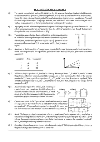
  • 1. QUESTION FOR SHORT ANSWER Q.1 Theelectricstrengthofairisabout30, 000 V/cm.Bythiswe meanthat whenthe electricfieldintensity exceeds this value,a spark will jump through the air.We saythat “electric breakdown” has occurred. Usingthisvalue, estimate the potential difference betweentwo objects wherea spark jumps.Atypical situation might be the spark that jumps between your body and a metal door handle after you have walked on a deep carpet or slid across a plastic car seat in verydryweather. Q.2 Ifyougraspthetwowiresleadingfromthetwoplates ofachargedcapacitor,youmayfeelashock.The effect is much greater for a 2–F capacitor than for a 0.02F capacitor, even though both are are charged tothesamepotential difference.Why? Q.3 Threeinfinitenonconductingsheets,withuniformsurfacechargedensities ,2and3arearrangedtobeparallellikethetwosheetsin Fig.What is theirorder, from left toright, if the electricfield  E producedbythe arrangementhasmagnitudeE=0inoneregionandE=2/0 inanother region? Q.4 As shown in the figure plots of charge versus potential difference for three parallel plate capacitors, which havetheplateareas andseparationsgiveninthetable. Which oftheplots goes withwhichofthe capacitors? Capacitor Area Separation 1 A d 2 2A d 3 A 2d Q.5 Initially, a single capacitance C1 iswiredto a battery.Then capacitance C2 isadded in parallel.Are (a) thepotential difference across C1 and (b)thecharge q1 on C1 nowmore than, less than, orthesame as previously? (c) Is theequivalent capacitance C12 of C1 and C2 more than, less than,or equal to C1 ? (d) Is the total charge stored on C1 and C2 together more than, less than, or equal to the charge stored previouslyonC1 ? Q.6 Asshowninthefigurethreecircuits,eachconsistingof a switch and two capacitors, initially charged as indicated.Aftertheswitcheshavebeenclosed,inwhich circuit(ifany)willthechargeontheleft–handcapacitor (a) increase, (b) decrease and (c) remain thesame? Q.7 Cap-monster maze. In the Figureallthe capacitorshavea capacitance of 6.0F, and all thebatteries have an emf of 10V.What is thecharge oncapacitorC?(Ifyoucan findtheproperloopthroughthismaze, you can answerthequestion with a few seconds of mental calculation.) Q.8 An oil filled capacitor has been designed to have a capacitance C and to operate safely at or below a certainmaximumpotential differenceVm withoutarcingover. However, thedesignerdidnot doagood job and thecapacitor occasionallyarcs over.What can be done to redesign the capacitor, keeping C andVm unchanged andusingthesamedielectric? Q.9 One of the plates of a capacitor connected to batteryis earthed. Will the potential diffrence between the plates change if the earthing wire is removed?
  • 2. ONLY ONE OPTION IS CORRECT. Take approx. 2 minutes for answering each question. Q.1 Thedistance between plates of aparallel platecapacitoris5d. Letthe positively charged plate is at x=0 and negatively charged plate is at x=5d. Two slabs one of conductor and other of a dielectric of equal thickness d areinserted between the platesas shown in figure. Potentialversusdistancegraphwill looklike: (A) (B) (C) (D) Q.2 Aparallelplatecapacitorhastwolayersofdielectricasshowninfigure. Thiscapacitorisconnectedacrossabattery.Thegraphwhichshows thevariationof electricfield(E)anddistance(x)fromleftplate. (A) (B) (C) (D) Q.3 Thedistancebetweentheplates ofacharged parallel platecapacitoris5 cm andelectricfieldinsidethe plates is 200Vcm–1.An uncharged metal bar of width 2 cm is fullyimmersed into thecapacitor. The length of the metal bar is same as that of plate of capacitor. The voltage across capacitor after the immersionofthebaris (A) zero (B) 400 V (C) 600 V (D) 100 V Q.4 Threelargeplates are arranged asshown.Howmuchchargewill flow through thekeyk ifit is closed? (A) 6 Q5 (B) 3 Q4 (C) 2 Q3 (D) none Q.5 FiveconductingparallelplateshavingareaAandseparationbetweenthemd,areplaced as shownin thefigure. Platenumber 2 and 4 are connected wire and between pointA andB, a cell ofemfE isconnected. Thechargeflown through thecell is (A) d AE 4 3 0 (B) d AE 3 2 0 (C) d AE4 0 (D) d2 AE0 Q.6 Ifchargeonleftplaneofthe5Fcapacitorinthecircuitsegmentshown inthe figureis–20C,thechargeonthe right plate of3Fcapacitoris (A) +8.57 C (B) –8.57 C (C) +11.42 C (D) –11.42 C Q.7 Fiveidentical capacitorplatesarearranged such that theymake capacitors each of 2 F. The plates are connected to a source of emf 10 V. The charge on plate C is (A) + 20 C (B) + 40 C (C) + 60 C (D) + 80 C
  • 3. Q.8 A capacitor of capacitance C is charged to a potential differenceV from a cell and then disconnected from it.Acharge+Q is now given to itspositiveplate.The potential difference across thecapacitor is now (A) V (B) V + C Q (C) V + C2 Q (D) V – C Q , if V < CV Q.9 In the circuitshown infigure chargestoredinthecapacitor of capacity5 f is (A) 60 C (B) 20 C (C) 30 C (D) zero Q.10 Aconductingbody1 has someinitialchargeQ,anditscapacitanceisC.Therearetwootherconducting bodies, 2 and 3, having capacitances : C2 = 2C and C3  . Bodies 2 and 3 are initiallyuncharged. "Body2 is touched with body1. Then, body 2 is removed from body1 and touched withbody3, and then removed."Thisprocess is repeated N times. Then, the chargeon body1 at theend must be (A) Q/3N (B) Q/3N–1 (C) Q/N3 (D) None Q.11 CondenserAhas acapacityof15 F whenitisfilledwith amediumofdielectricconstant15.Another condenserB has a capacity1 F withair between the plates.Both are chargedseparatelybya battery of100V.After charging, both are connected in parallelwithout the batteryand thedielectric material beingremoved.Thecommonpotential nowis (A) 400V (B) 800V (C) 1200V (D) 1600V Q.12 Intheadjoiningfigure,capacitor(1)and(2)haveacapacitance‘C’each.Whenthedielectricofdielectric consatntKisinsertedbetweentheplatesofoneofthecapacitor,thetotalchargeflowingthroughbatteryis (A) 1K KCE  from B to C (B) 1K KCE  from C to B (C) )1K(2 CE)1K(   from B to C (D) )1K(2 CE)1K(   from C to B Q.13 Twoidenticalcapacitors1and2areconnectedinseriestoabatteryasshownin figure.Capacitor2containsadielectricslabofdielectricconstantkasshown.Q1 andQ2 arethechargesstoredinthecapacitors.Nowthedielectric slabisremovedandthecorrespondingchargesareQ’1 andQ’2.Then (A) k 1k Q Q 1 1    (B) 2 1k Q Q 2 2    (C) k2 1k Q Q 2 2    (D) 2 k Q Q 1 1   Q.14 Thearea oftheplates of aparallel platecapacitor isAand the gap betweenthem is d.Thegap is filled withanon-homogeneousdielectricwhosedielectricconstantvaries withthedistance‘y’fromoneplate as : K = sec(y/2d),where  is a dimensionless constant. Thecapacitance ofthis capacitoris (A) 0A / 2d (B) 0A /d (C) 20A /d (D) none Q.15 Acapacitor stores 60C chargewhen connected across a battery.When thegap between theplates is filled with a dielectric , a charge of 120C flows through the battery. The dielectric constant of the materialinsertedis: (A) 1 (B) 2 (C) 3 (D) none
  • 4. Q.16 In the abovequestion,iftheinitial capacitanceofthecapacitorwas 2F, theamountof heat produced whenthedielectricisinserted. (A) 3600J (B) 2700J (C) 1800J (D) none Q.17 AcapacitorofcapacitanceC isinitiallycharged toapotential differenceofVvolt. Nowitisconnected to a batteryof 2Vwith opposite polarity. The ratio of heat generated to the final energystored in the capacitorwillbe (A) 1.75 (B) 2.25 (C) 2.5 (D) 1/2 Q.18 Three plates A, B and C each of area 0.1 m2 are separated by 0.885 mm fromeach other as shownin thefigure.A10Vbatteryis used to chargethe system. The energystoredinthe system is (A) 1 J (B) 10–1 J (C) 10–2 J (D) 10–3 J Q.19 A parallel plate capacitor of capacitance C is connected to a battery and is charged to a potential differenceV.Anothercapacitor ofcapacitance2Cissimilarlychargedtoapotential difference2V.The charging batteryisnowdisconnected and the capacitors are connect in parallelto each other in such a waythat thepositiveterminal ofoneisconnectedtothe negativeterminal oftheother.Thefinal energy oftheconfigurationis (A) zero (B) 2 3 CV2 (C) 6 25 CV2 (D) 2 9 CV2 Q.20 A 2 F capacitor is charged to a potential = 10V. Another 4 F capacitor is charged to a potential = 20V.Thetwo capacitorsare then connected in a singleloop, with thepositiveplateof one connected with negativeplateoftheother.What heat isevolvedinthecircuit? (A) 300 J (B) 600 J (C) 900 J (D) 450 J Q.21 The platesS andTofanuncharged parallel plate capacitor are connectedacrossa battery.The battery is then disconnected and the charged plates are now connectedin asystemas shown inthe figure.The system shownis inequilibrium.Allthestrings areinsulatingandmassless.Themagnitudeofchargeon oneof thecapacitorplates is: [Area ofplates =A] (A) 0 mgA2  (B) k mgA4 0 (C) 0 mgA  (D) k mgA2 0 Q.22 In thecircuit shown, theenergystored in 1Fcapacitor is (A) 40 J (B) 64 J (C) 32 J (D) none Q.23 Fourmetallicplatesarearrangedasshowninthefigure.Ifthedistancebetweeneachplatethencapacitance ofthegiven system between pointsAand B is (Givend <<A) (A) d A0 (B) d A2 0 (C) d A3 0 (D) d A4 0
  • 5. Q.24 What is the equivalent capacitance of the system of capacitors between A& B (A) 7 6 C (B) 1.6 C (C) C (D) None Q.25 From a supplyofidenticalcapacitors rated 8F, 250V, theminimumnumber ofcapacitors required to form a composite 16 F, 1000 V is : (A) 2 (B) 4 (C) 16 (D) 32 Q.26 Theminimumnumberofcapacitorseachof3Frequiredtomakeacircuitwithanequivalentcapacitance 2.25 F is (A) 3 (B) 4 (C) 5 (D) 6 Q.27 The capacitance (C)for an isolated conductingsphere of radius (a) is given by40a. If the sphere is enclosed withanearthed concentricsphere. Theratioofthe radiiofthespheres being )1n( n  then the capacitance of such a sphere will be increasedbya factor (A) n (B) )1n( n  (C) n )1n(  (D) a . n Q.28 Two capacitor having capacitances 8 F and 16 F have breaking voltages 20 V and 80 V.Theyare combinedinseries.Themaximumchargetheycanstoreindividuallyinthecombinationis (A) 160 C (B) 200 C (C) 1280 C (D) noneofthese Q.29 A capacitor of capacitance 1 F withstands the maximum voltage 6 kV while a capacitor of 2 F withstands themaximumvoltage4 kV.Whatmaximum voltagewillthe system ofthesetwo capacitor withstands iftheyareconnected inseries? (A) 10 kV (B)12 kV (C) 8 kV (D) 9 kV Q.30 Four identical plates 1, 2, 3 and 4 are placed parallel to each other at equal distance as shown in the figure. Plates 1 and 4 are joined together and the space between 2 and 3 is filled with a dielectric of dielectric constant k = 2. The capacitance of the system between 1 and 3 & 2 and 4 are C1 and C2 respectively.The ratio 2 1 C C is: (A) 3 5 (B) 1 (C) 5 3 (D) 7 5 Q.31 Inthecircuitshowninfigure,theratioofchargeson5F and4F capacitoris: (A) 4/5 (B)3/5 (C) 3/8 (D) 1/2 Q.32 In the circuit shown, a potential difference of 60Vis applied acrossAB. The potential differencebetween the point M and N is (A) 10 V (B) 15 V (C) 20 V (D) 30 V
  • 6. Q.33 Find theequivalent capacitance acrossA& B (A) 3 28 f (B) 2 15 F (C) 15 F (D) none Q.34 Acapacitorofcapacitance1Fwithstandsthemaximumvoltages6KVwhileacapacitorofcapacitance 2.0 F with standsthe maximum voltage =4KV. ifthe twocapacitorsare connected inseries, then the twocapacitors combined cantakeupamaximumvoltage of (A) 2.4 KV (B) 5 KV (C) 9 KV (D) 10 KV Q.35 Thediagram showsfourcapacitors withcapacitances andbreakdownvoltages asmentioned. Whatshould bethe maximum value ofthe externalemf source suchthatnocapacitorbreaks down?[Hint: Firstofall find out thebreakdown voltages ofeach branch.After thatcomparethem.] (A) 2.5 kV (B) 10 / 3kV (C) 3 kV (D) 1 kV Q.36 Three capacitors 2 F, 3 F and 5 F can withstand voltages to 3V, 2V and 1V respectively. Their seriescombinationcanwithstandamaximumvoltageequalto (A) 5 Volts (B) (31/6)Volts (C) (26/5)Volts (D) None Q.37 Find equivalentcapacitance acrossAB(all capacitancesinF) (A) F 3 20  (B) 9F (C) 48 F (D) None Q.38 Three longconcentricconductingcylindrical shells haveradii R,2Rand 22 R.Innerandouter shells areconnectedtoeach other.Thecapacitance across middleandinner shells perunitlengthis: (A) 2n 3 1 0 l  (B) 2n 6 0 l  (C) 2n 0 2l  (D) None Q.39 A charged capacitor is allowedto discharge through a resistance 2 byclosing the switch S at the instant t = 0.At time t = ln 2 s, the reading of the ammeter fallshalfofitsinitialvalue.Theresistanceoftheammeterequalto (A) 0 (B) 2 (C)  (D) 2M Q.40 AcapacitorC=100Fisconnectedtothreeresistoreachofresistance 1 k and a battery of emf 9V. The switch S has been closed for long time so as to charge the capacitor. When switch S is opened, the capacitordischargeswith timeconstant (A) 33 ms (B) 5 ms (C) 3.3 ms (D) 50 ms Q.41 A capacitor C = 100 F is connected to three resistors each ofresistance 1 kW and a batteryof emf 9V. Theswitch S has been closed forlong time so asto chargethe capacitor.When switch S isopened,the capacitordischarges withtime constant. (A) 33 ms (B) 5 ms (C) 3.3 ms (D) 50 ms
  • 7. Q.42 In thetransientshown thetimeconstantofthecircuitis: (A) 3 5 RC (B) 2 5 RC (C) RC 4 7 (D) RC 3 7 Q.43 In thecircuit shown in figure C1=2C2. SwitchS is closed at time t=0. Let i1 and i2 be the currents flowing through C1 and C2 at anytime t, then the ratio i1/ i2 (A) isconstant (B)increases withincreaseintimet (C) decreases with increase intimet (D) first increasesthendecreases Q.44 Find heatproducedin the capacitorson closingtheswitchS (A) 0.0002 J (B) 0.0005 J (C) 0.00075 (D) zero Q.45 In thecircuit shown, when thekeyk is pressed at time t = 0, which of thefollowingstatements about current Iin the resistorABis true (A) I = 2mA at all t (B) Ioscillatesbetween 1 mAand 2mA (C) I = 1 mA at all t (D)At t = 0, I= 2mAand with time it goes to 1 mA Q.46 In the R–Ccircuit shown in thefigure the total energyof 3.6 ×10⁻³ J is dissipated in the 10  resistor when theswitch S isclosed.Theinitial charge onthe capacitoris (A) 60 C (B) 120 C (C) 60 2 C (D) 2 60 C Q.47 A charged capacitor is allowed to discharge through a resistor byclosingthe keyat the instant t =0.At the instant t = (ln 4) s, the reading of the ammeter fallshalftheinitial value. Theresistanceoftheammeterisequalto (A) 1 M (B) 1 (C) 2 (D) 2M Q.48 In thecircuit shown, the cell is ideal, with emf= 15V. Eachresistanceis of3.Thepotential differenceacross thecapacitor is (A) zero (B) 9 V (C) 12 V (D) 15 V Question No. 49 to 52 (4 questions) In thecircuitshown in figure, fourcapacitors are connected to a battery. Q.49 Theequivalentcapacitanceofthecircuitis (A) 25 F (B) 6 F (C) 8.4 F (D) none
  • 8. Q.50 The charge on the 5 F capacitor is (A) 60 C (B) 24 C (C) 12 C (D) 20 C Q.51 The potential difference across the 6 Fcapacitor is (A) 6V (B) 4V (C) 5V (D) none Q.52 Themaximumenergyisstored inthecapacitorof (A) 10 F (B) 6 F (C) 5 F (D) 4 F Q.53 Aparallelplatecapacitorhasanelectricfieldof105V/mbetweentheplates.Ifthechargeonthecapacitor plate is 1C, then theforce on each capacitor plate is (A) 0.1Nt (B) 0.05Nt (C) 0.02Nt (D) 0.01Nt Q.54 Acapacitoris connected to a battery. The force of attraction between the plates when the separation betweenthemis halved (A)remainsthesame (B)becomeseighttimes (C)becomes fourtimes (D) becomes two times ONE OR MORE THAN ONE OPTION MAY BE CORRECT Take approx. 3 minutes for answering each question. Q.1 AparallelplatecapacitorAisfilledwithadielectricwhosedielectricconstantvarieswithappliedvoltage as K =V.An identical capacitorBofcapacitanceC0 with airas dielectricisconnectedtovoltagesource V0 = 30V and then connected to thefirst capacitorafter disconnecting the voltagesource. Thecharge and voltageoncapacitor. (A) Aare 25C0 and 25V (B)A are 25C0 and 5 V (C) B are 5c0 and 5V (D) B are 5C0 and 25 V Q.2 Two capacitors of 2 F and 3 F are charged to 150 volt and 120 voltrespectively.The plates ofcapacitorareconnectedas shown inthefigure.Adischargedcapacitorofcapacity1.5F falls tothe free ends ofthe wire. Then (A) charge on the 1.5 F capacitors is 180 C (B) charge on the 2F capacitor is 120 C (C)chargeflows throughAfromrighttoleft. (D)chargeflows throughAfromleft toright. Q.3 Inthecircuitshown,each capacitorhasacapacitanceC.TheemfofthecellisE.IftheswitchS is closed (A)positivechargewillflowoutofthepositiveterminalofthecell (B)positivechargewillenterthepositiveterminalofthecell (C)theamountofchargeflowingthroughthecellwillbeCE. (D) theamountof charge flowingthrough thecellwillbe4/3 CE. Q .4 In thecircuitshow n initially C 1, C2 are uncharged.After closing the switch (A) The charge on C2 is greater that on C1 (B) The charge on C1 and C2 are the same (C) The potential drops across C1 and C2 are the same (D) The potential drops across C2 is greater than that across C1
  • 9. Q.5 Aparallelplateair-corecapacitorisconnected across asourceofconstantpotential difference. Whena dielectricplateisintroducedbetweenthe twoplates then : (A) somecharge from the capacitorwill flow back intothe source. (B) someextrachargefrom thesourcewill flowback intothecapacitor. (C)theelectric field intensitybetweenthe two platedoes not change. (D) theelectricfieldintensitybetween the twoplates will decrease. Q.6 A parallel platecapacitorhas a parallel sheet ofcopperinsertedbetween and parallel tothetwo plates, without touchingtheplates. Thecapacityofthecapacitor aftertheintroductionofthe coppersheetis: (A)minimum whenthe coppersheet touches oneofthe plates. (B)maximum when the copper sheet touches oneofthe plates. (C)invariantforall positions ofthe sheet between theplates. (D)greaterthan that beforeintroducingthe sheet. Q.7 In the circuitshown in the figure, the switchS is initiallyopenand the capacitor isinitiallyuncharged. I1, I2 and I3 representthecurrentinthe resistance 2, 4 and 8 respectively. (A) Just after the switch S is closed, I1 = 3A, I2 = 3A and I3 = 0 (B) Just after the switch S is closed, I1 = 3A, I2 = 0 and I3 = 0 (C) long time after the switch S is closed, I1 = 0.6A, I2 = 0 and I3 = 0 (D) long after the switch S is closed, I1 = I2 = I3 = 0.6A. Q.8 Thecircuitshownin thefigureconsists ofabatteryofemf=10V;acapacitor of capacitance C = 1.0 F and three resistor of values R1 = 2, R2 = 2 and R3 = 1. Initiallythe capacitor is completelyuncharged and the switch S is open. The switch S is closed at t = 0. (A) The current through resistor R3 atthemoment the switch closedis zero. (B) The current throughresistor R3 a longtimeafter the switchclosed is 5A. (C)Theratio ofcurrent through R1 and R2 isalways constant. (D)Themaximumcharge onthecapacitorduringtheoperationis5C. Q.9 In the circuit shown in figure C1 = C2 = 2F.Then chargestored in (A) capacitor C1 is zero (B) capacitor C2 is zero (C) both capacitor is zero (D) capacitor C1 is 40 C Q.10 A capacitor of capacity C is charged to a steady potential difference V and connected in series with an open keyand a pure resistor'R'.At time t = 0, the keyis closed. If I= current at time t, aplot of logIagainst 't' is asshown in (1) in thegraph. Lateroneoftheparameters i.e.V, R or C ischanged keepingthe other two constant, and the graph (2)is recorded. Then (A) C is reduced (B) C is increased (C) R is reduced (D) R is increased
  • 10. Question No.11 to 12 (2 questions) The charge across thecapacitorintwodifferent RC circuits1 and 2 are plottedas shown in figure. Q.11 Choosethe correctstatement(s)related tothetwocircuits. (A) Both thecapacitors are charged to the same charge. (B)Theemf'sofcells inboththecircuit are equal. (C)Theemf's ofthe cellsmaybedifferent. (D) Theemf E1 is morethan E2 Q.12 Identifythe correct statement(s) related to the R1, R2, C1 and C2 of thetwo RC circuits. (A) R1 > R2 if E1 = E2 (B) C1 < C2 if E1 = E2 (C) R1C1 > R2C2 (D) 2 1 R R < 1 2 C C Q.13 Aparallel plate capacitor is charged byconnecting it to a battery. The batteryis disconnected and the plates of the capacitor are pulled apart to make the separation between the plates twice.Again the capacitorisconnectedto the battery(withsamepolarity) then (A)Charge from the batteryflows intothecapacitorafter reconnection (B)Chargefrom capacitorflows intothebatteryafter reconnection. (C) The potential difference between theplates increases when theplates arepulledapart. (D)Afterreconnectionofbatterypotentialdifferencebetweentheplatewillimmediatelybecomeshalfof theinitialpotentialdifference.(Justafterdisconnectingthebattery) Q.14 The plates of a parallel plate capacitor with no dielectric are connected to a voltage source. Now a dielectric of dielectric constant K is inserted to fill the whole space between the plates with voltage sourceremaining connectedtothe capacitor. (A) the energystoredinthecapacitorwill become Ktimes (B)theelectricfieldinsidethecapacitorwilldecreasetoKtimes (C) theforce ofattraction betweentheplateswill increaseto K2–times (D) thechargeon the capacitorwillincrease toKtimes Q.15 Fourcapacitors andabatteryareconnectedasshown.Thepotential drop across the 7 F capacitor is 6 V. Then the : (A) potential difference across the3 F capacitoris 10 V (B) charge on the 3 F capacitor is 42 C (C) e.m.f.of thebatteryis 30 V (D) potential difference across the12 F capacitor is 10V. Q.16 A circuit shown in the figure consists of a battery of emf 10 V and two capacitance C1 and C2 of capacitances 1.0F and 2.0F respectively. The potential differenceVA –VB is 5V (A) charge on capacitor C1 is equal to charge on capacitor C2 (B)Voltage across capacitor C1 is 5V. (C) Voltage across capacitor C2 is 10 V (D) Energystored in capacitor C1 is two times the energystoredin capacitor C2. Q.17 A capacitor C is charged to a potential difference V and batteryis disconnected. Now if thecapacitor platesarebrought close slowlybysomedistance: (A) some +ve work is done byexternal agent (B) energyofcapacitor will decrease (C) energyofcapacitorwill increase (D) none of theabove
  • 11. Q.18 The capacitance ofaparallel platecapacitorisC when the regionbetween the platehasair.Thisregion isnowfilled with adielectricslab ofdielectricconstantk.ThecapacitorisconnectedtoacellofemfE, and the slab is taken out (A) chargeCE(k – 1)flows through thecell (B) energyE2C(k – 1) is absorbed bythe cell. (C) the energy stored in the capacitor is reduced byE2C(k – 1) (D) the external agent has to do 1 2 E2C(k – 1) amount of work to take theslab out. Q.19 Two capacitors ofcapacitances 1Fand 3F are charged to the samevoltages5V.Theyareconnected inparallel withoppositelychargedplatesconnectedtogether.Then: (A)Final commonvoltagewill be5V. (B)Finalcommonvoltage will be2.5 V (C) Heat producedin the circuitwillbezero. (D) Heat producedin thecircuit will be 37.5J Q.20 The two plates X andYof a parallel plate capacitor of capacitance C are given a chargeof amount Q each. X isnow joined tothepositive terminal andYto the negative terminal ofa cell ofemfE = Q/C. (A)ChargeofamountQwillflowfromthenegativeterminaltothepositiveterminalofthecellinsideit. (B) Thetotalchargeon theplate X will be 2Q. (C)The totalchargeon theplateYwill bezero. (D)ThecellwillsupplyCE2 amountofenergy. Q.21 Adielectricslab isinserted betweenthe plates ofanisolated chargedcapacitor.Whichofthe following quantitieswillremainthesame? (A) theelectricfieldinthe capacitor (B) thechargeon thecapacitor (C)the potential differencebetween theplates (D) thestored energyin thecapacitor. Q.22 The separationbetween theplatesofa isolated chargedparallelplate capacitoris increased.Which of thefollowingquantitieswillchange? (A) chargeon thecapacitor (B)potential differenceacrossthe capacitor (C)energyof thecapacitor (D) energydensitybetween the plates. Q.23 Eachplateofaparallelplatecapacitorhasachargeqonit.Thecapacitorisnowconnectedtoabattery.Now, (A) the facingsurfaces ofthe capacitor haveequal and oppositecharges. (B) thetwo plates of thecapacitorhave equal and opposite charges. (C)thebatterysupplies equal and opposite charges to thetwo plates. (D) theouter surfaces oftheplates have equal charges. Q.24 Followingoperations can beperformed ona capacitor: X – connect the capacitor to a batteryof emf E. Y – disconnect the battery Z – reconnect the batterywith polarityreversed. W – inserta dielectricslab in the capacitor (A) In XYZ(perform X, thenY, then Z) thestoredelectricenergyremains unchangedand no thermal energyisdeveloped. (B)The chargeappearing on thecapacitor isgreater aftertheactionXWYthan afterthe action XYW. (C)TheelectricenergystoredinthecapacitorisgreateraftertheactionWXYthanaftertheactionXYW. (D) The electricfield in the capacitor after the action XWis thesame as thatafter WX. Q.25 Aparallelplatecapacitorischargedandthendisconnectedfromthesourceofpotentialdifference.Ifthe plates of thecondenser are then moved farther apart bythe useof insulated handle, which one of the followingistrue? (A) thechargeon the capacitor increases (B) the charge on the capacitor decreases (C)thecapacitance ofthecapacitor increases (D)thepotential difference across theplate increases
  • 12. Q.26 Aparallel plate capacitor is charged and then disconnected from thesourcesteadyE.M.F.The plates are then drawn apart farther.Again itis connected to thesamesource. Then : (A) the potential difference across the plate increases, while theplatesarebeing drawnapart. (B) the chargefrom the capacitor flows into thesource, whenthecapacitoris reconnected. (C) morechargeis drawn to the capacitor from thesource, duringthe reconnection. (D) the electricintensitybetween theplatesremains constantduringthedrawingapartofplates. Q.27 Whena parallel plates capacitor is connectedto a sourceofconstant potential difference, (A) all the chargedrawn from the source is storedin thecapacitor. (B) all theenergydrawn fromthe sourceis stored in thecapacitor. (C)thepotential difference across thecapacitorgrows veryrapidlyinitiallyand this ratedecreases to zeroeventually. (D) thecapacityofthecapacitorincreases with the increaseofthechargeinthecapacitor. Q.28 When twoidenticalcapacitors arechargedindividuallytodifferentpotentialsandconnectedparallel to each other,after disconnectingthem fromthesource: (A)net chargeonconnected plates islessthan thesum ofinitial individual charges. (B)net chargeonconnected platesequalsthesum ofinitial charges. (C)thenetpotentialdifferenceacrossthemisdifferentfromthesumoftheindividualinitialpotentialdifferences. (D)thenetenergystoredinthetwo capacitors islessthan thesum oftheinitial individual energies. Q.29 Aparallel platecapacitorofplateareaAand plateseperation d ischarged topotential differenceVand thenthebatteryisdisconnected.AslabofdielectricconstantKistheninsertedbetweentheplates ofthe capacitor soas tofill thespace between the plates.IfQ,E andWdenoterespectively,themagnitudeof chargeon eachplate, theelectric fieldbetween the plates (after theslabis inserted)and the workdone onthesystem,inquestion,inthe processofinsertingthe slab,then (A) Q = d AV0 (B) Q = d KAV0 (C) E = dK V (D) W = –         K 1 1 d2 AV2 0 Q.30 Aparallel plate capacitor is connected to a battery. The quantities charge, voltage, electric field and energyassociated with the capacitor are given byQ0, V0, E0 and U0 respectively.Adielectric slab is introducedbetweenplates ofcapacitor butbatteryis stillin connection. The correspondingquantities now given by Q,V, E and U related to previous ones are (A) Q > Q0 (B) V > V0 (C) E > E0 (D) U < U0 Q.31 Aparallel-platecapacitorisconnected toacell.ItspositiveplateAandits negativeplateBhavecharges +Q and –Q respectively. A third plate C, identical to A and B, with charge +Q, is now introduced midwaybetweenAand B, parallel tothem.Which ofthefollowingarecorrect? (A) The charge on theinnerface of B is now 2 Q3  (B)Thereisnochange inthe potential difference betweenAand B. (C)The potential difference betweenAandC isone-third ofthepotential difference betweenB and C. (D) Thechargeon theinner face ofAis now 2Q . Q.32 Two capacitors C1 = 4 F and C2 = 2F are charged to same potential V = 500 Volt,butwith oppositepolarityasshowninthefigure.TheswitchesS1 and S2 are closed. (A) Thepotentialdifference acrossthetwocapacitors are sameand is given by V3500 (B) Thepotentialdifference acrossthetwocapacitors are sameand is given by V31000 (C)Theratiooffinalenergytoinitial energyofthesystem is1/9. (D) Theratiooffinal energytoinitial energyofthesystem is4/9.
  • 13. Q.33 Aparallelplatecapacitorischargedtoacertainpotentialandthe chargingbatteryisthen disconnected. Now, if theplates of thecapacitor are movedapart then: (A) The stored energyof thecapacitor increases (B) Chargeonthecapacitor increases (C)Voltage of the capacitor decreases (D) The capacitance increases Q.34 If a batteryof voltage V is connected across terminals I of the block box showninfigure,an ideal voltmeterconnectedtoterminalsIIgivesareading ofV/2, whileifthe batteryisconnectedto terminalsII,avoltmeter across terminals I readsV.The black box may contain (A) (B) (C) (D) Q.35 Two capacitors of equal capacitance (C1 = C2) are shown in the figure. Initially, whiletheswitchS isopen,oneofthecapacitorsisunchargedand theothercarries charge Q0. The energystored in thecharged capacitoris U0. Sometimes after the switch is closed, the capacitors C1 and C2 carry chargesQ1 and Q2, respectively; the voltagesacrossthecapacitors areV1 and V2; and the energiesstored in the capacitorsare U1 and U2.Which of the followingstatements isINCORRECT? (A) Q0 = 2 1 (Q1 + Q2) (B) Q1 = Q2 (C) V1 = V2 (D) U1 = U2 (E) U0 = U1 + U2 Question No.36 to 39 (4 questions) The figureshowsa diagonal symmetricarrangementofcapacitors anda battery Q.36 Identifythecorrectstatements. (A) Both the 4F capacitorscarryequal charges in opposite sense. (B) Both the 4F capacitorscarryequal charges in same sense. (C) VB – VD > 0 (D) VD – VB > 0 Q.37 If thepotential ofC iszero, then (A) VA = + 20V (B) 4(VA – VB) + 2(VD – VB) = 2VB (C) 2(VA – VD) + 2(VB – VD) = 4VD (D) VA = VB + VD Q.38 Thepotentialof the point B and D are (A) VB = 8V (B) VB = 12V (C) VD = 8V (D) VD = 12V
  • 14. Q.39 The valueof charge q1, q2 and q3 as shown in the figure are (A) q1 = 32 C ; q2 = 24 C ; q3 = – 8 C (B) q1 = 48 C ; q2 = 16 C ; q3 = + 8 C (C) q1 = 32 C ; q2 = 24 C ; q3 = + 8 C (D) q1 = 3 C ; q2 = 4 C ; q3 = + 2 C Q.40 IfQisthechargeontheplatesofacapacitorofcapacitanceC,Vthepotentialdifferencebetweentheplates, Atheareaofeachplateanddthedistancebetweentheplates,theforceofattractionbetweentheplatesis (A)          A Q 2 1 0 2 (B)         d CV 2 1 2 (C)         0 2 A CV 2 1 (D)          2 0 2 d Q 4 1