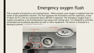
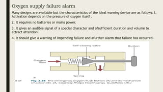
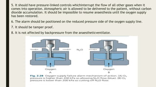
Emergency oxygen flush
This is usually activated by a non-locking button . When pressed, pure oxygen is supplied from the
outlet of the anaesthetic machine. The flow bypasses the flowmeters and the vaporizers. A flow
of about 35–75 L/min at a pressureof about 400 kPa is expected. The emergency oxygen flush is
usually activated by a non-locking button and using a self-closing valve. It is designed to minimize
unintended and accidental operation by staff or other equipment. The button is recessed in a
housing to prevent accidental depression.
Problems in practice and safety features
1. The high operating pressure and flow of the oxygen flush puts the patient at a higher risk of
barotrauma
2. When the emergency oxygen flush is used inappropriately, it leads to dilution of the
anaesthetic gases and possible awareness.
3. It should not be activated while ventilating a patient using a minute volume divider
ventilator.
Oxygen supply failure alarm
Many designs are available but the characteristics of the ideal warning device are as follows:1.
Activation depends on the pressure of oxygen itself .
2. It requires no batteries or mains power.
3. It gives an audible signal of a special character and ofsufficient duration and volume to
attract attention.
4. It should give a warning of impending failure and afurther alarm that failure has occurred.
5. It should have pressure-linked controls whichinterrupt the flow of all other gases when it
comes into operation. Atmospheric air is allowed to be delivered to the patient, without carbon
dioxide accumulation. It should be impossible to resume anaesthesia until the oxygen supply
has been restored.
6. The alarm should be positioned on the reduced pressure side of the oxygen supply line.
7. It should be tamper proof.
8. It is not affected by backpressure from the anaestheticventilator.
Common gas outlet
The common gas outlet is where the anaesthetic machine ‘ends’. At the common gas outlet,
the gas mixture made at the flowmeters, plus any inhaled anaesthetic agent added by the
vaporizer, exits the machine and enters the fresh gas tubing that conducts it to the breathing
system. The common gas outlet isa conically tapered pipe with a 22 mm male/15 mm female
connector fitting. It can be fixed or on a swivelling connector. The connector of the common
gas outlet should be strong enough to withstand a torque of up to 10 Nm because of the heavy
equipment that may be attached.
33.pptx

33.pptx

  • 2.
    Emergency oxygen flush Thisis usually activated by a non-locking button . When pressed, pure oxygen is supplied from the outlet of the anaesthetic machine. The flow bypasses the flowmeters and the vaporizers. A flow of about 35–75 L/min at a pressureof about 400 kPa is expected. The emergency oxygen flush is usually activated by a non-locking button and using a self-closing valve. It is designed to minimize unintended and accidental operation by staff or other equipment. The button is recessed in a housing to prevent accidental depression.
  • 3.
    Problems in practiceand safety features 1. The high operating pressure and flow of the oxygen flush puts the patient at a higher risk of barotrauma 2. When the emergency oxygen flush is used inappropriately, it leads to dilution of the anaesthetic gases and possible awareness. 3. It should not be activated while ventilating a patient using a minute volume divider ventilator.
  • 4.
    Oxygen supply failurealarm Many designs are available but the characteristics of the ideal warning device are as follows:1. Activation depends on the pressure of oxygen itself . 2. It requires no batteries or mains power. 3. It gives an audible signal of a special character and ofsufficient duration and volume to attract attention. 4. It should give a warning of impending failure and afurther alarm that failure has occurred.
  • 5.
    5. It shouldhave pressure-linked controls whichinterrupt the flow of all other gases when it comes into operation. Atmospheric air is allowed to be delivered to the patient, without carbon dioxide accumulation. It should be impossible to resume anaesthesia until the oxygen supply has been restored. 6. The alarm should be positioned on the reduced pressure side of the oxygen supply line. 7. It should be tamper proof. 8. It is not affected by backpressure from the anaestheticventilator.
  • 6.
    Common gas outlet Thecommon gas outlet is where the anaesthetic machine ‘ends’. At the common gas outlet, the gas mixture made at the flowmeters, plus any inhaled anaesthetic agent added by the vaporizer, exits the machine and enters the fresh gas tubing that conducts it to the breathing system. The common gas outlet isa conically tapered pipe with a 22 mm male/15 mm female connector fitting. It can be fixed or on a swivelling connector. The connector of the common gas outlet should be strong enough to withstand a torque of up to 10 Nm because of the heavy equipment that may be attached.