Download to read offline


![Chapter 14 File I/O
LabVIEW User Manual 14-12 ni.com
Creating Configuration Files
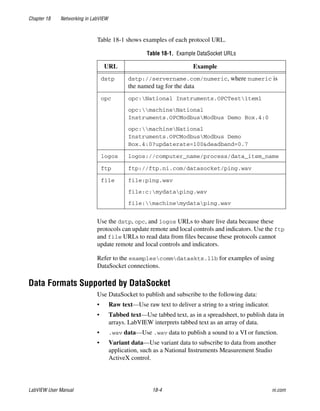
Use the Configuration File VIs to read and create standard Windows
configuration settings (.ini) files and to write platform-specific data, such
as paths, in a platform-independent format so that you can use the files
these VIs generate across multiple platforms. The Configuration File VIs
do not use a standard file format for configuration files. While you can use
the Configuration File VIs on any platform to read and write files created
by the VIs, you cannot use the Configuration File VIs to create or modify
configuration files in a Mac OS or UNIX format.
Refer to the examplesfileconfig.llb for examples of using the
Configuration File VIs.
Note The standard extension for Windows configuration settings files is .ini, but the
Configuration File VIs work with files with any extension, provided the content is in the
correct format. Refer to the Windows Configuration Settings File Format section of this
chapter for more information about configuring the content.
Using Configuration Settings Files
A standard Windows configuration settings file is a specific format for
storing data in a text file. You can programmatically access data within the
.ini file easily because it follows a specific format.
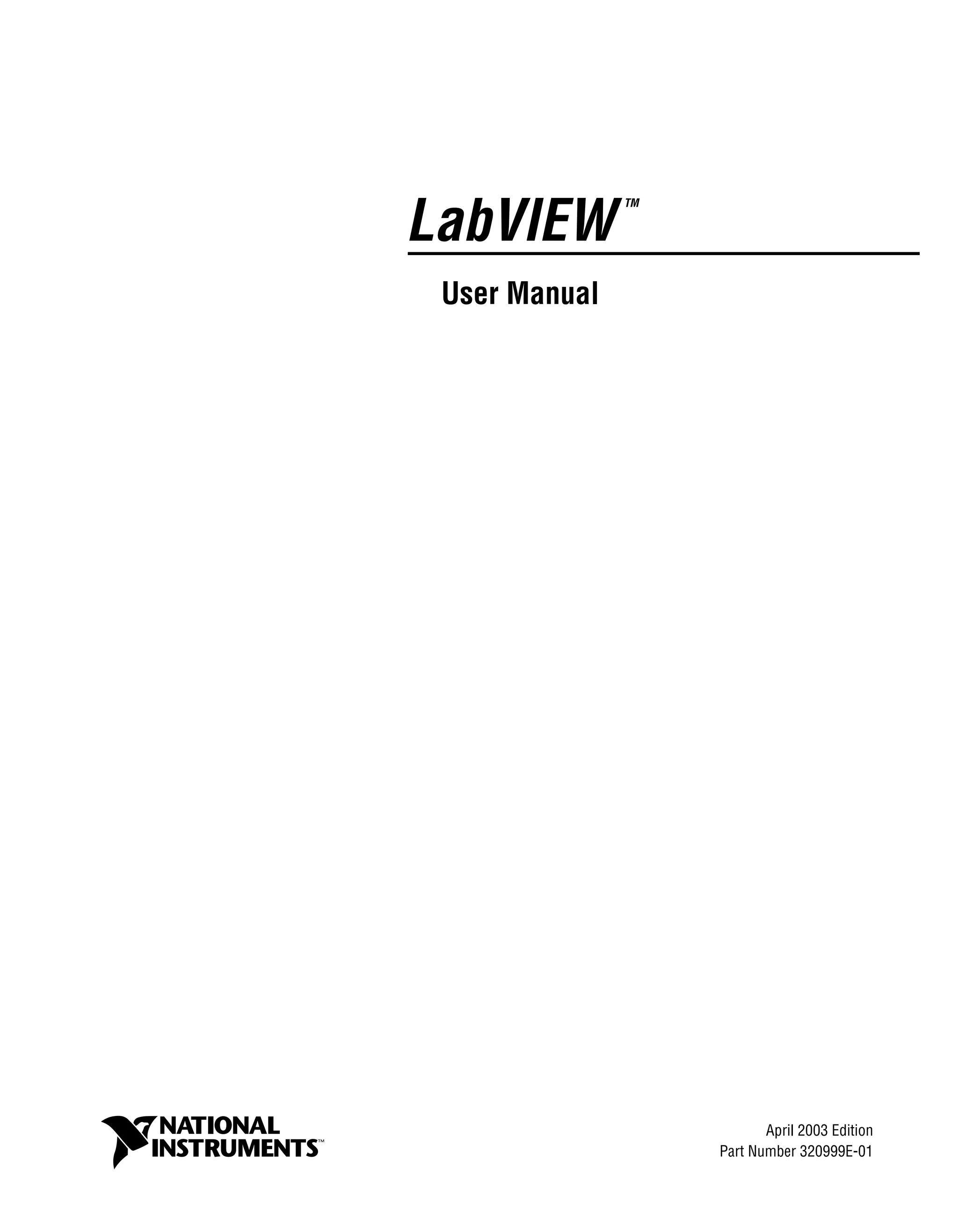
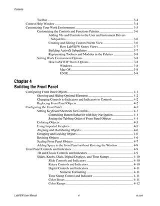
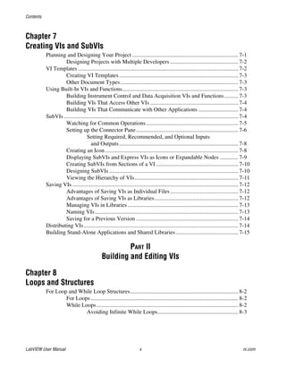
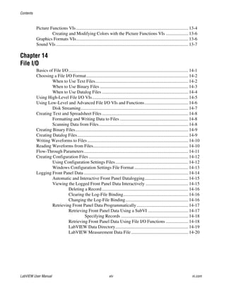
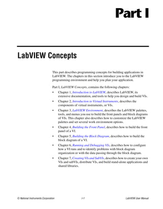
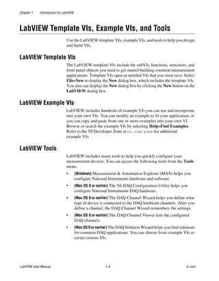
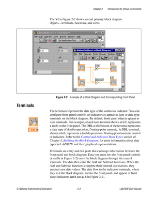
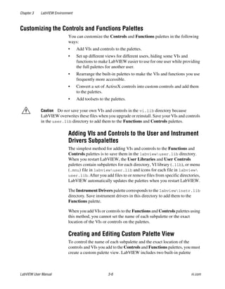
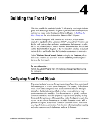
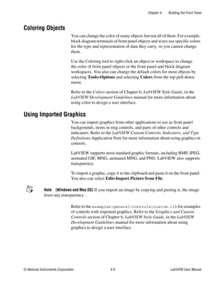
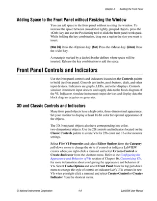
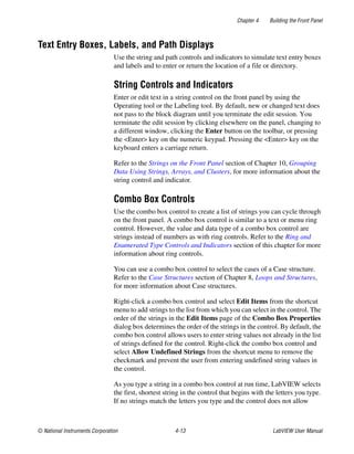
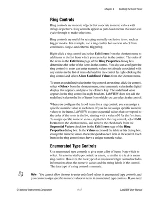
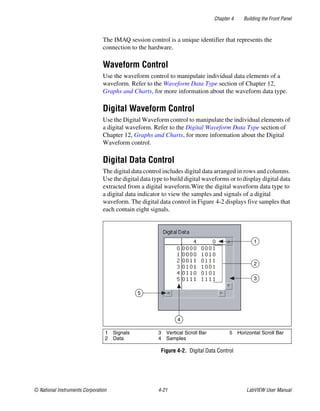
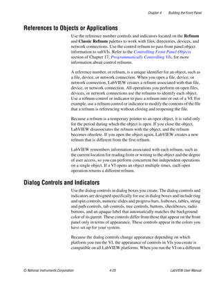
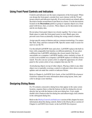
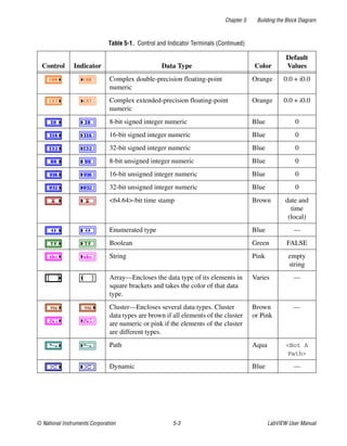
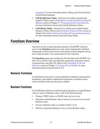
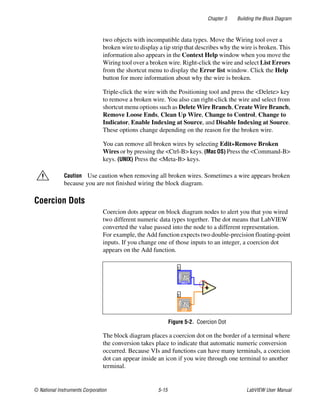
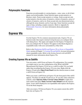
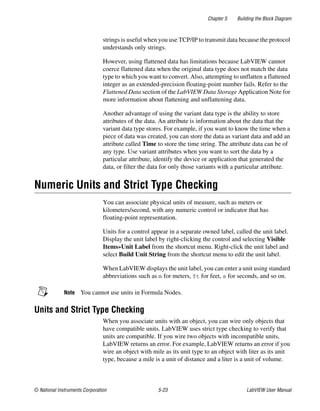
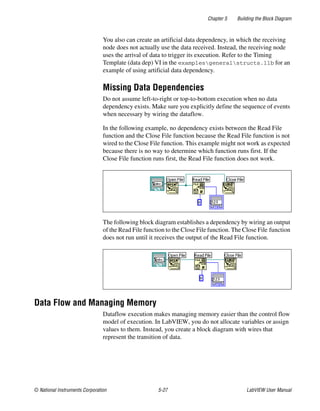
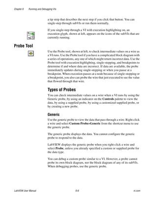
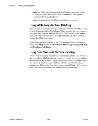
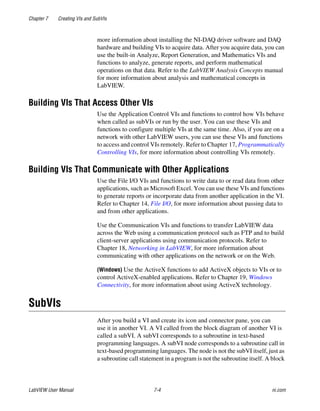
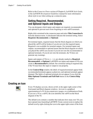
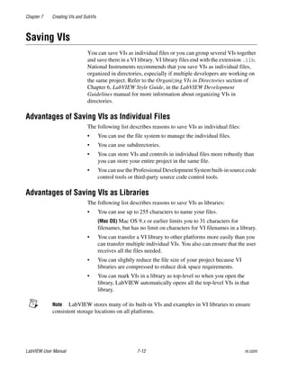
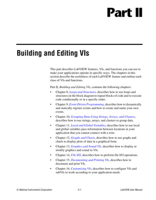
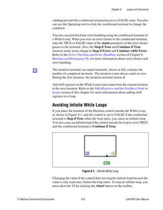
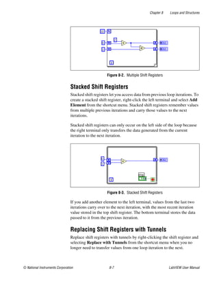
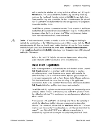
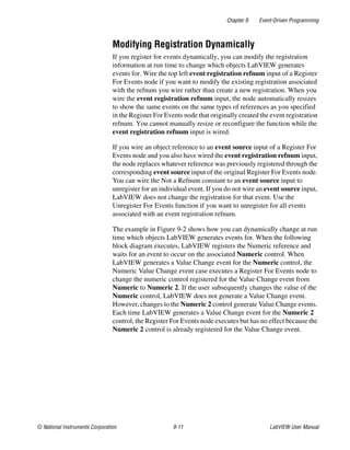
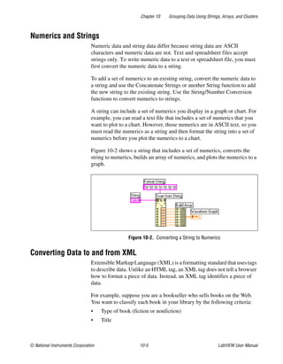
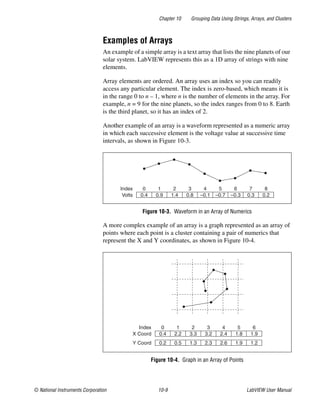
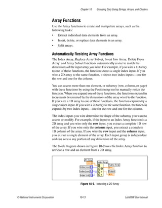
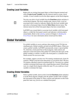
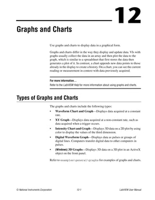
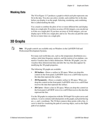
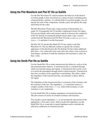
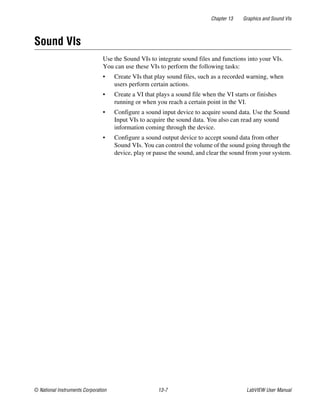
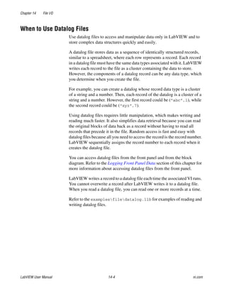
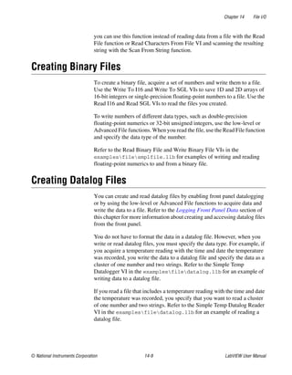
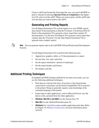
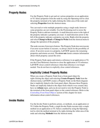
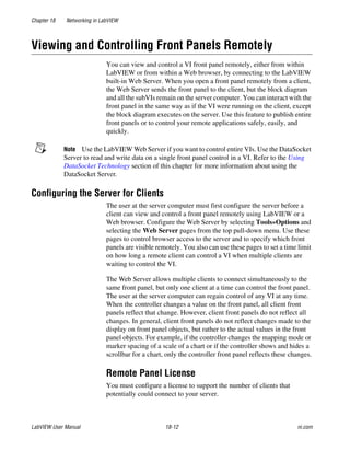
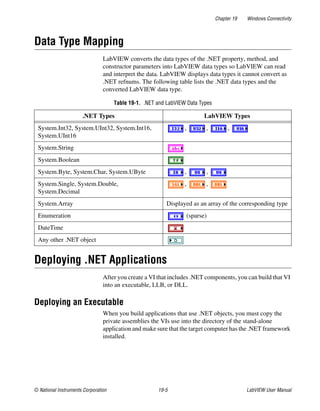
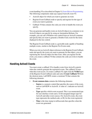
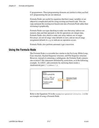
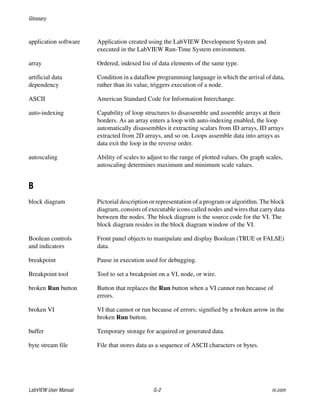
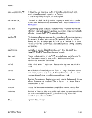
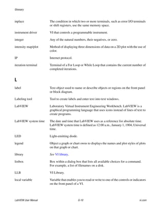
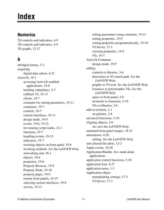
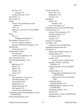
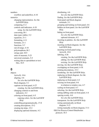
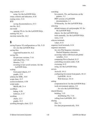
For example, consider a configuration settings file with the following
contents:
[Data]
Value=7.2
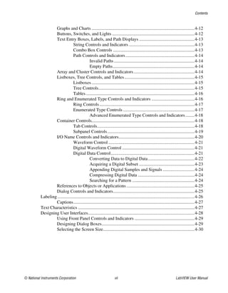
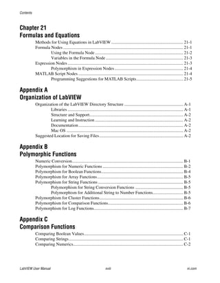
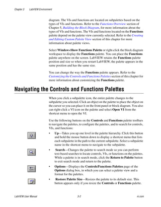
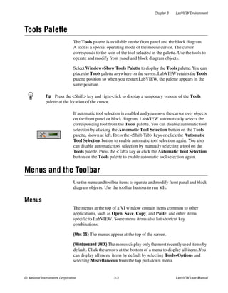
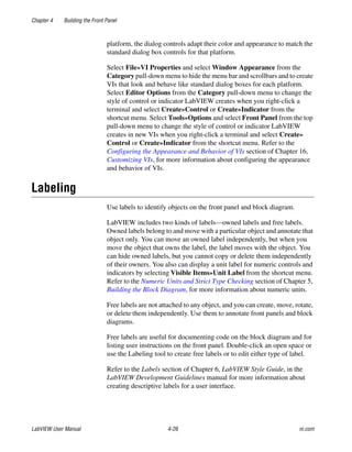
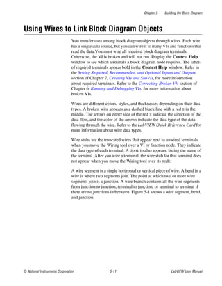
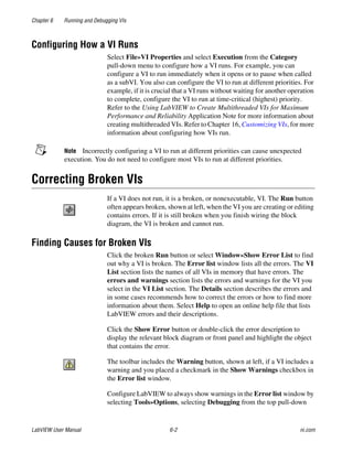
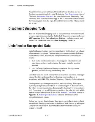
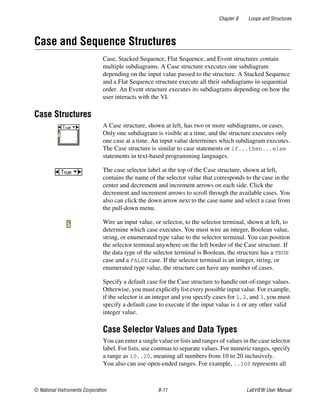
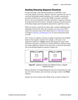
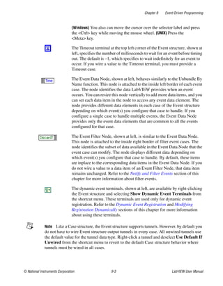
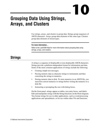
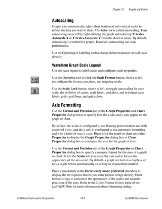
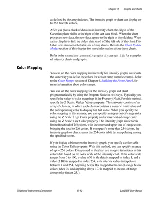
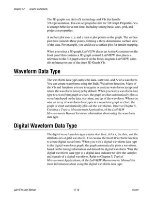
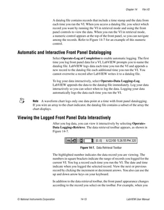
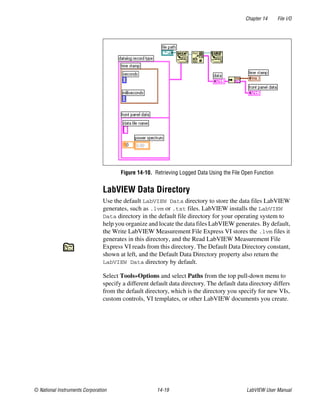
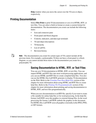
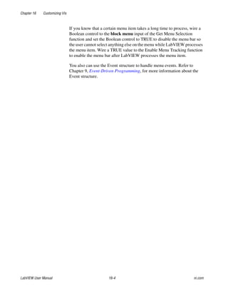
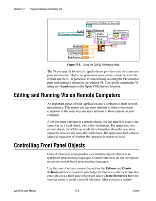
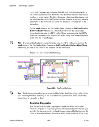
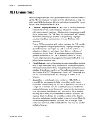
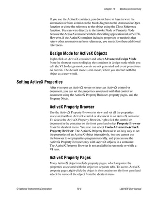
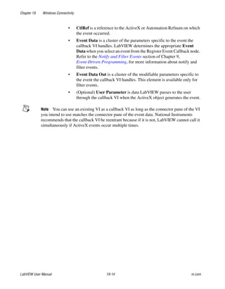
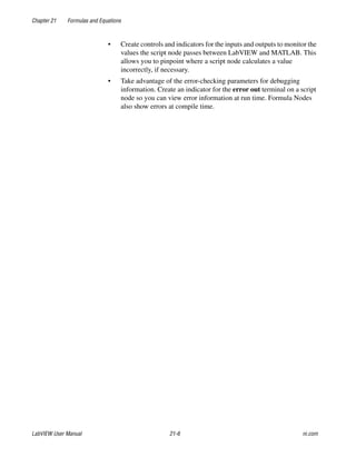
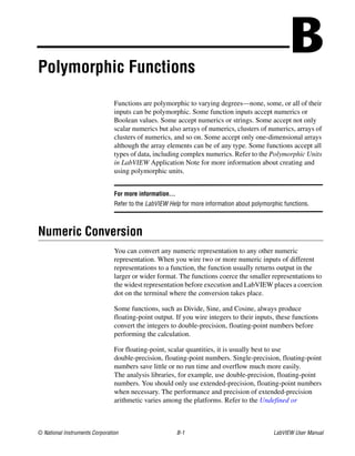
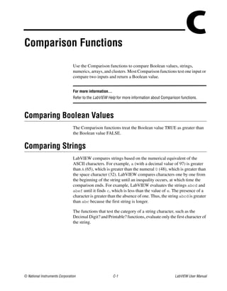
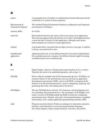
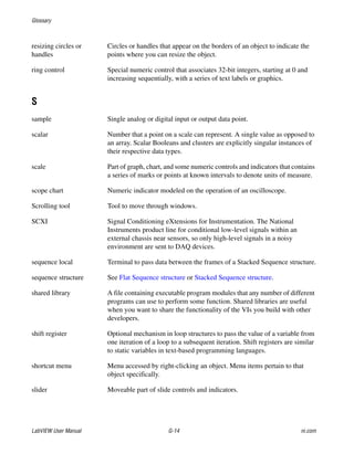
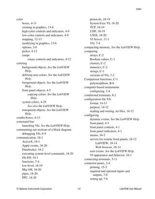
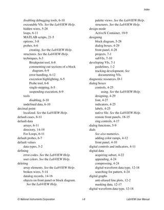
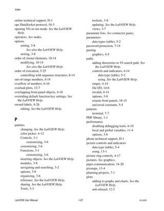
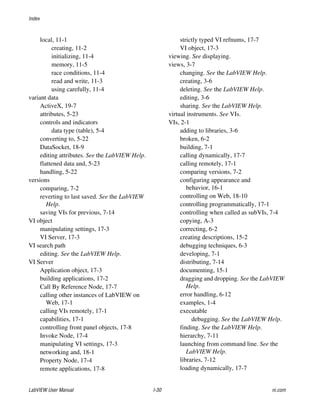
You can use the Configuration File VIs to read this data, as shown in
Figure 14-6. This VI uses the Read Key VI to read the key named Value
from the section called Data. This VI works regardless of how the file
changes, provided the file remains in the Windows configuration settings
file format.](https://image.slidesharecdn.com/320999e-160512030253/85/320999e-217-320.jpg)
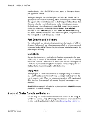
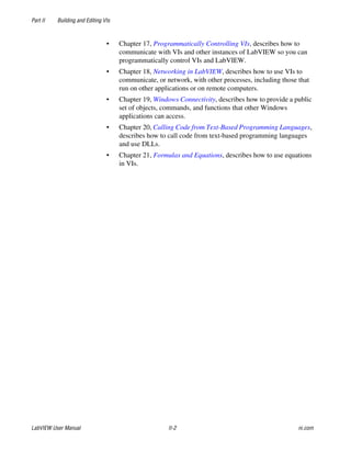
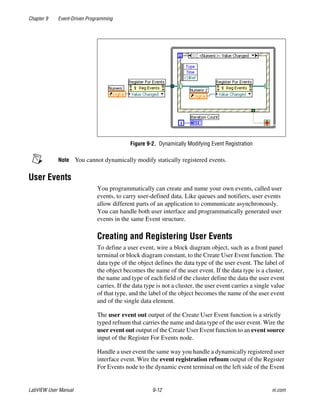
![Chapter 14 File I/O
© National Instruments Corporation 14-13 LabVIEW User Manual
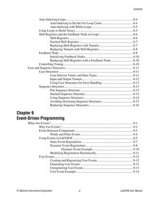
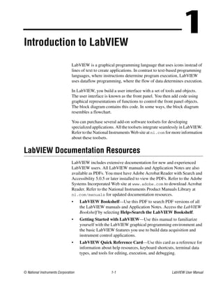
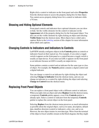
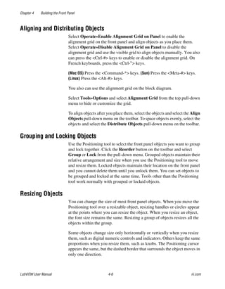
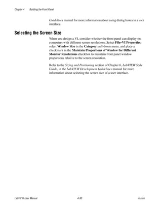
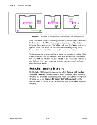
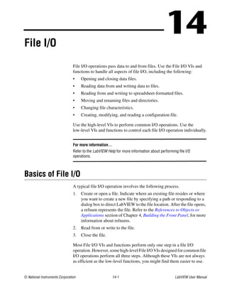
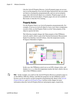
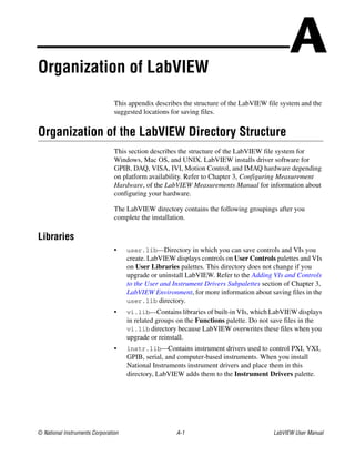
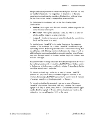
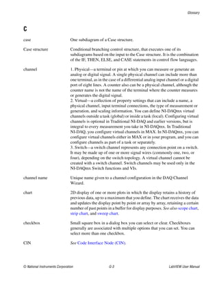
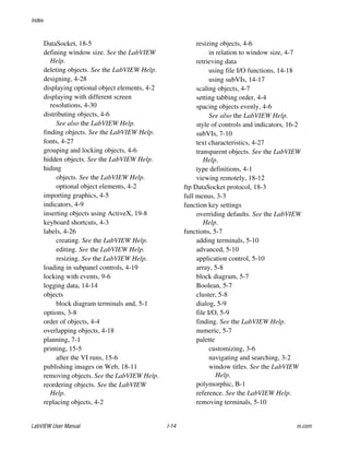
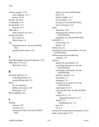
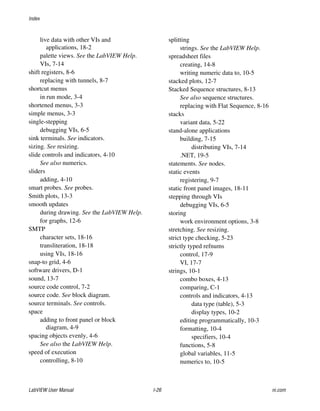
Figure 14-6. Reading Data from an .ini File
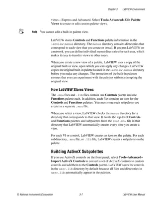
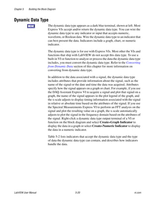
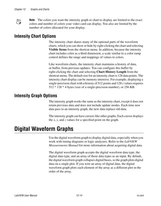
Windows Configuration Settings File Format
Windows configuration settings files are text files divided into named
sections. Brackets enclose each section name. Every section name in a file
must be unique. The sections contain key/value pairs separated by an equal
sign (=). Within each section, every key name must be unique. The key
name represents a configuration preference, and the value name represents
the setting for that preference. The following example shows the
arrangement of the file:
[Section 1]
key1=value
key2=value
[Section 2]
key1=value
key2=value
Use the following data types with Configuration File VIs for the value
portion of the key parameter:
• String
• Path
• Boolean
• 64-bit double-precision floating-point numeric
• 32-bit signed integer
• 32-bit unsigned integer
The Configuration File VIs can read and write raw or escaped string data.
The VIs read and write raw data byte-for-byte, without converting the data
to ASCII. In converted, or escaped, strings LabVIEW stores any
non-displayable text characters in the configuration settings file with the
equivalent hexadecimal escape codes, such as 0D for a carriage return.
In addition, LabVIEW stores backslash characters in the configuration](https://image.slidesharecdn.com/320999e-160512030253/85/320999e-218-320.jpg)
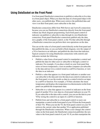
![Chapter 18 Networking in LabVIEW
© National Instruments Corporation 18-3 LabVIEW User Manual
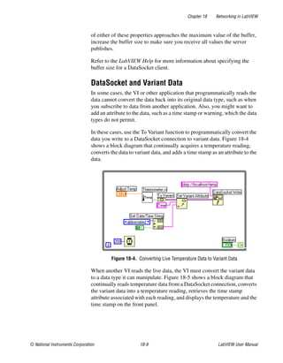
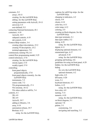
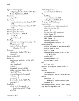
For example, if you want to share the data in a thermometer indicator on the
front panel with other computers on the Web, publish the thermometer data
by specifying a URL in the DataSocket Connection dialog box. Users on
other computers subscribe to the data by placing a thermometer on their
front panel and selecting the URL in the DataSocket Connection dialog
box. Refer to the Using DataSocket on the Front Panel section of this
chapter for more information about using DataSocket technology on the
front panel.
Refer to the Integrating the Internet into Your Measurement System white
paper for more information about DataSocket technology. This white paper
is available as a PDF from the Installation CD, in the manuals directory,
or from the National Instruments Web site at ni.com.
Specifying a URL
URLs use communication protocols, such as dstp, ftp, and file, to
transfer data. The protocol you use in a URL depends on the type of data
you want to publish and how you configure your network.
You can use the following protocols when you publish or subscribe to data
using DataSocket:
• DataSocket Transport Protocol (dstp)—The native protocol for
DataSocket connections. When you use this protocol, the VI
communicates with the DataSocket Server. You must provide a named
tag for the data, which is appended to the URL. The DataSocket
connection uses the named tag to address a particular data item on a
DataSocket Server. To use this protocol, you must run a DataSocket
Server.
• (Windows) OLE for Process Control (opc)—Designed specifically
for sharing real-time production data, such as data generated by
industrial automation operations. To use this protocol, you must run an
OPC server.
• (Windows) logos—An internal National Instruments technology for
transmitting data between the network and your local computer.
• File Transfer Protocol (ftp)—You can use this protocol to specify a
file from which to read data.
Note To read a text file from an FTP site using DataSocket, add [text] to the end of the
DataSocket URL.
• file—You can use this protocol to provide a link to a local or network
file that contains data.](https://image.slidesharecdn.com/320999e-160512030253/85/320999e-248-320.jpg)
![Chapter 18 Networking in LabVIEW
LabVIEW User Manual 18-18 ni.com
receives text designated as using the ISO Latin-1 character set, it converts
the text to the Mac OS character set.
Transliteration
Transliteration is the mapping of characters to another character set. Use
transliteration if you are sending an email and you need to change the text
of the email to the corresponding characters in another character set. You
can use the SMTP E-mail VIs to specify character sets that map text to
another character set before sending the text. For example, if you create a
message using standard ASCII characters and specify that the character set
is MacRoman, the SMTP E-mail VIs transliterate the text and send it as
character set iso-8859-1 (ISO Latin-1). Use the translit input parameter
of the SMTP E-mail VIs to specify which transliterations the VIs can use.
A transliteration is defined by a virtual character set, a target character set,
and a transliteration, or mapping, file. The transliteration file specifies that
one character maps to another character.
The transliteration file is a binary file of 256 bytes with 256 entries. Each
entry in the file corresponds to a character in the virtual character set, and
contains the new character code from the target character set. For example,
if you want to map the a character, whose code is 61, to the A character,
whose code is 41, the entry with an index of 61 in the transliteration file
should contain the value 41. If an entry contains a value that equals its
index, the transliteration file does not modify the character in the virtual
character set. For example, if the entry with an index of 61 in the
transliteration file contains a value of 61, the transliteration file does not
modify the character.
When you specify a transliteration file as the target character set in the
translit input, the mappings are applied in the order specified. For example,
if the transliteration entry is [MacRoman iso-8859-1 macroman.trl,
MacRomanUp MacRoman asciiup.trl], the character set MacRoman
changed to iso-8859-1 using macroman.trl and then MacRomanUp
changed to MacRoman using asciiup.trl. Refer to the vi.lib
UtilitySMTP directory for examples of .trl files.](https://image.slidesharecdn.com/320999e-160512030253/85/320999e-263-320.jpg)
![Appendix B Polymorphic Functions
LabVIEW User Manual B-2 ni.com
Unexpected Data section of Chapter 6, Running and Debugging VIs,
for more information about floating-point overflow.
For integers, it is usually best to use a 32-bit signed integer.
If you wire an output to a destination that has a different numeric
representation, LabVIEW converts the data according to the following
rules:
• Signed or unsigned integer to floating-point number—Conversion
is exact, except for 32-bit integers to single-precision, floating-point
numbers. In this case, LabVIEW reduces the precision from 32 bits to
24 bits.
• Floating-point number to signed or unsigned integer—LabVIEW
moves out-of-range values to the integer’s minimum or maximum
value. Most integer objects, such as the iteration terminal of a For
Loop, round floating-point numbers. LabVIEW rounds a fractional
part of 0.5 to the nearest even integer. For example, LabVIEW rounds
6.5 to 6 rather than 7.
• Integer to integer—LabVIEW does not move out-of-range values to
the integer’s minimum or maximum value. If the source is smaller than
the destination, LabVIEW extends the sign of a signed source and
places zeros in the extra bits of an unsigned source. If the source is
larger than the destination, LabVIEW copies only the least significant
bits of the value.
Polymorphism for Numeric Functions
The arithmetic functions take numeric input data. With some exceptions
noted in the function descriptions, the output has the same numeric
representation as the input or, if the inputs have different representations,
the output is the wider of the inputs.
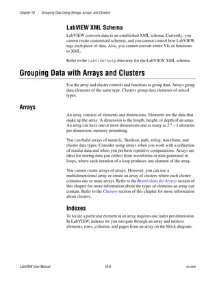
The arithmetic functions work on numbers, arrays of numbers, clusters of
numbers, arrays of clusters of numbers, complex numbers, and so on.
A formal and recursive definition of the allowable input type is as follows:
Numeric type = numeric scalar OR array [numeric type] OR cluster
[numeric types]
The numeric scalars can be floating-point numbers, integers, or complex
floating-point numbers. LabVIEW does not allow you to use arrays of
arrays.](https://image.slidesharecdn.com/320999e-160512030253/85/320999e-291-320.jpg)
![Appendix B Polymorphic Functions
LabVIEW User Manual B-4 ni.com
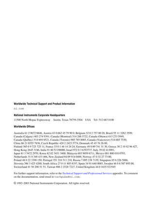
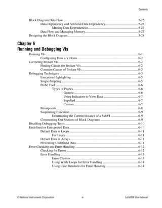
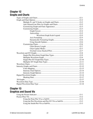
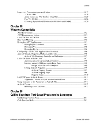
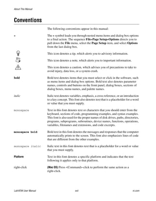
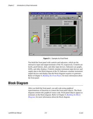
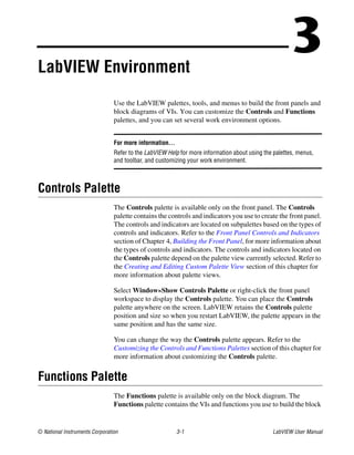
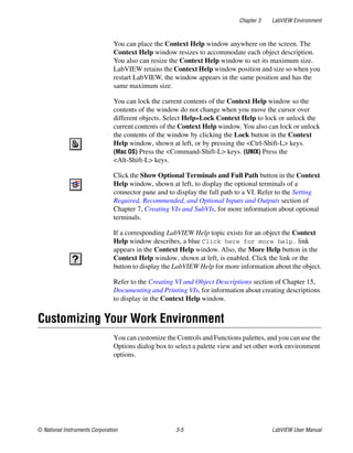
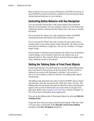
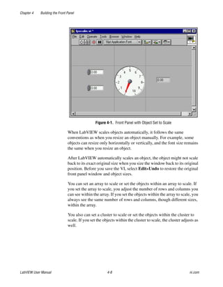
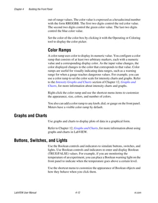
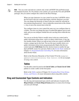
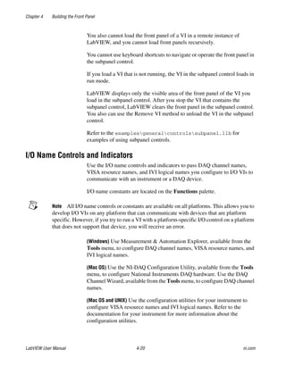
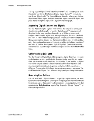
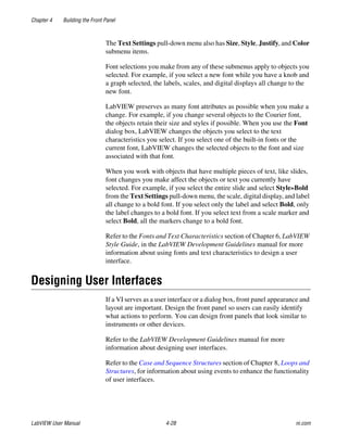
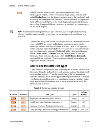
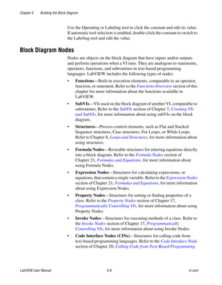
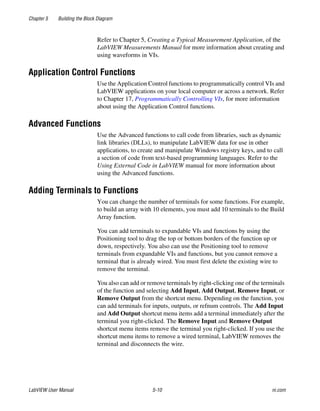
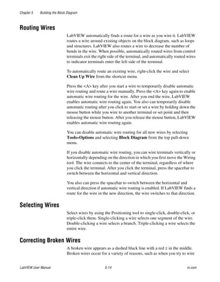
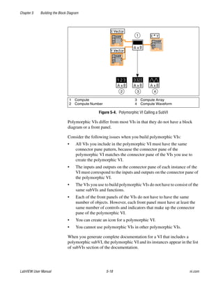
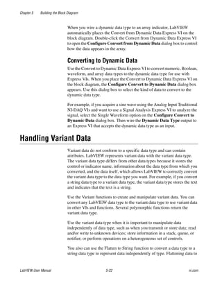
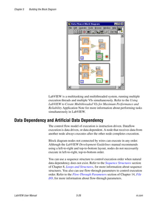
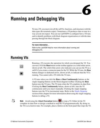
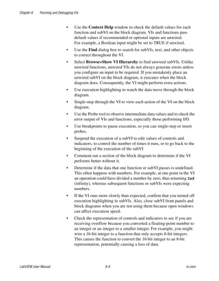
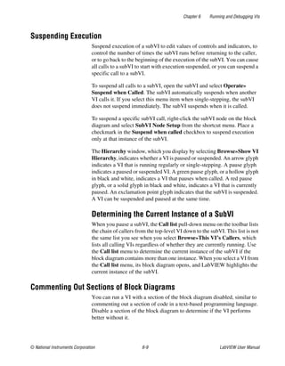
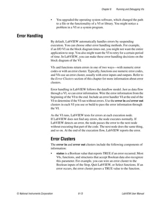
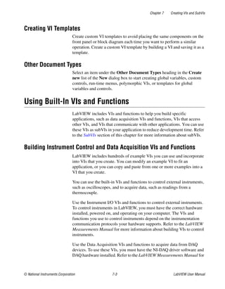
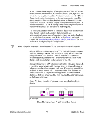
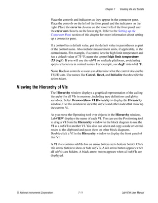
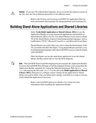
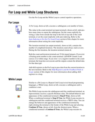
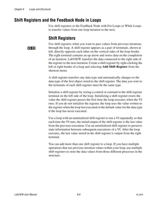
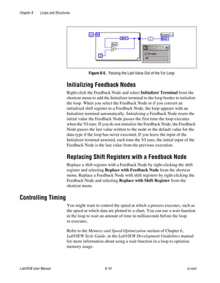
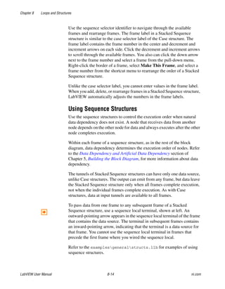
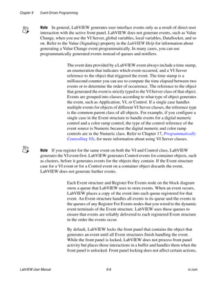
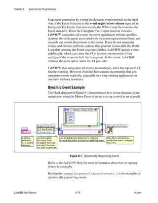
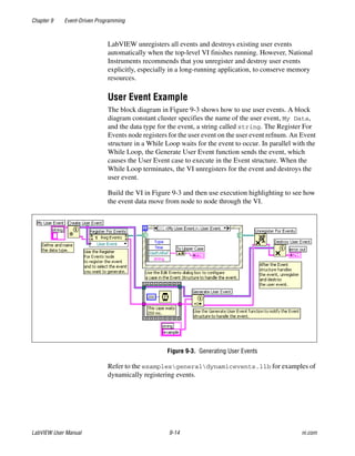
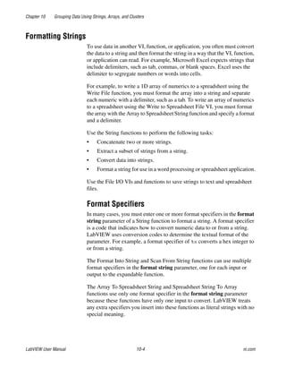
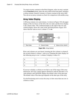
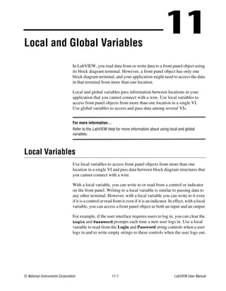
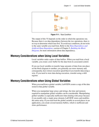
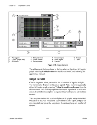
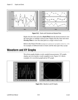
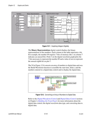
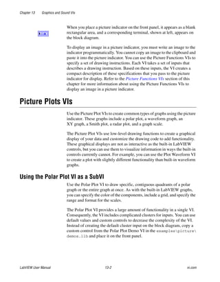
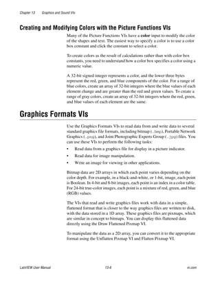
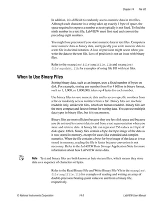
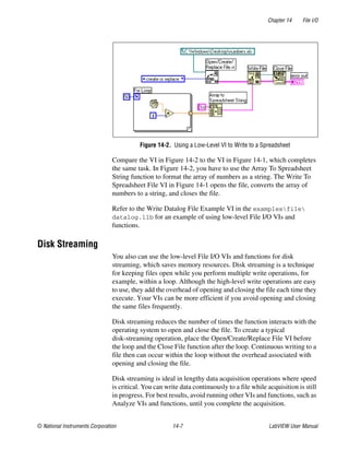
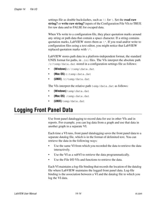
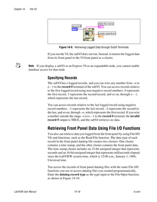
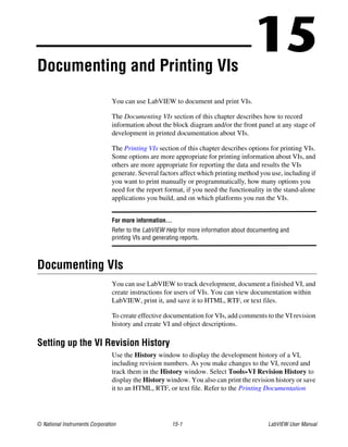
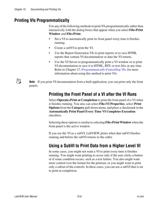
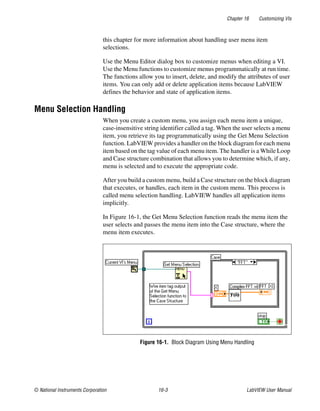
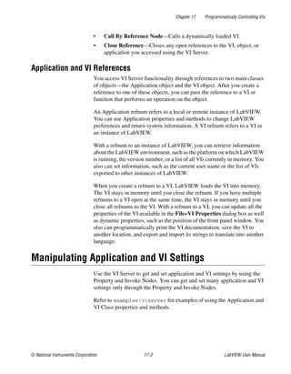
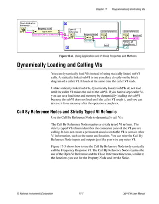
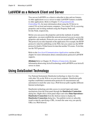
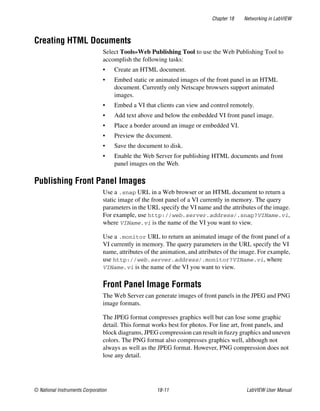
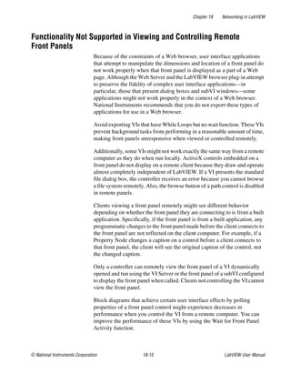
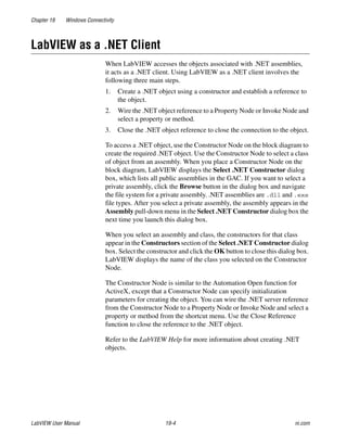
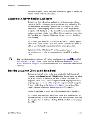
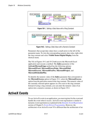
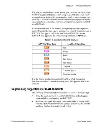
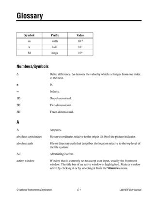
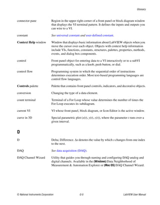
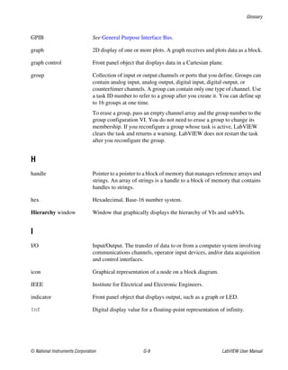
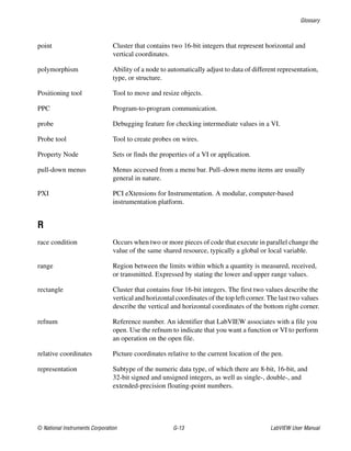
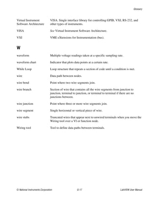
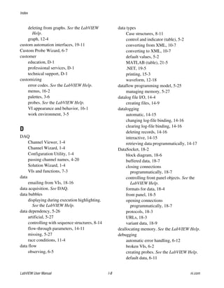
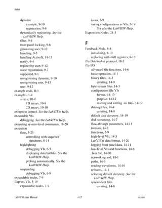
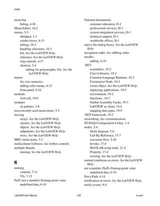
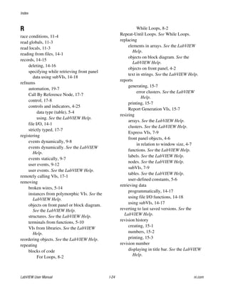
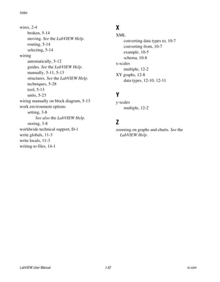
Figure B-1 shows the possible polymorphic combinations of the Add
function.
Figure B-1. Polymorphic Combinations of the Add Function
Polymorphism for Boolean Functions
The logical functions take either Boolean or numeric input data. If the input
is numeric, LabVIEW performs a bit-wise operation. If the input is an
integer, the output has the same representation. If the input is a
floating-point number, LabVIEW rounds it to a long integer, and the output
is a long integer.
The logical functions work on arrays of numbers or Boolean values,
clusters of numbers or Boolean values, arrays of clusters of numbers or
Boolean values, and so on.
A formal and recursive definition of the allowable input type is as follows:
Logical type = Boolean scalar OR numeric scalar OR
array [logical type] OR cluster [logical types]
except that complex numbers and arrays of arrays are not allowed.
Logical functions with two inputs can have the same input combinations as
the arithmetic functions. However, the logical functions have the further
restriction that the base operations can only be between two Boolean values
or two numbers. For example, you cannot have an AND between a Boolean
value and a number. Figure B-2 shows some combinations of Boolean
values for the AND function.
Similar
Scalar
Array
Cluster
Cluster
Cluster
Array
Array
Scalar
Scalar
Scalar
Array
Scalar
Cluster
Array
Cluster
One Scalar
Array of
Cluster
Array of Clusters
Array of Clusters](https://image.slidesharecdn.com/320999e-160512030253/85/320999e-293-320.jpg)
![Appendix B Polymorphic Functions
© National Instruments Corporation B-7 LabVIEW User Manual
You can use the Equal?, Not Equal?, Not A Number/Path/Refnum?, Empty
String/Path?, and Select functions with paths and refnums, but no other
Comparison functions accept paths or refnums as inputs.
Comparison functions that accept arrays and clusters normally return
Boolean arrays and clusters of the same structure. If you want the function
to return a single Boolean value, right-click the function and select
Comparison Mode»Compare Aggregates from the shortcut menu. Refer
to the Comparing Arrays and Clusters section of Appendix C, Comparison
Functions, for more information about how the function compares
aggregates.
Polymorphism for Log Functions
The Logarithmic functions take numeric input data. If the input is an
integer, the output is a double-precision, floating-point number. Otherwise,
the output has the same numeric representation as the input.
These functions work on numbers, arrays of numbers, clusters of numbers,
arrays of clusters of numbers, complex numbers, and so on. A formal and
recursive definition of the allowable input type is as follows:
Numeric type = numeric scalar OR array [numeric type] OR
cluster [numeric types]
except that arrays of arrays are not allowed.
Arrays can be any size and can have any number of dimensions. Clusters
can have any number of elements. The output type is of the same numeric
representation as the input, and the functions operate on each element of the
cluster or array. Refer to the Polymorphism for Numeric Functions section
of this appendix for more information about two-input polymorphic
functions. Allowable input type combinations for the two-input
Logarithmic functions include the following:
• Similar—Both inputs have the same structure, and the output has the
same structure as the inputs.
• One scalar—One input is a numeric scalar, the other is a numeric
array or cluster, and the output is an array or cluster.](https://image.slidesharecdn.com/320999e-160512030253/85/320999e-296-320.jpg)
![Appendix C Comparison Functions
© National Instruments Corporation C-3 LabVIEW User Manual
Compare Aggregates Mode
In Compare Aggregates mode, comparison functions return a single
Boolean result after comparing the elements in an array. Comparison
functions consider elements later in the array secondary to elements earlier
in the array. Therefore, the function performs the following steps to
determine the result of the comparison:
• The function compares corresponding elements in each input array,
starting at the beginning of the array.
• If the corresponding elements are not equal, the function stops—it
returns the result of this comparison.
• If the corresponding elements are equal, the Comparison function
processes the next pair of values, until it finds an inequality or reaches
the end of one of the input arrays.
• If all values in the input arrays are equal but one array has extra
elements at the end, the longer array is considered greater than the
shorter one. For example, a Comparison function considers the array
[1,2,3,2] to be greater than the array [1,2,3].
Clusters
Clusters you compare must include the same number of elements, each
element in the clusters must be of compatible types, and the elements must
be in the same cluster order. For example, you can compare a cluster of a
DBL and a string to a cluster of an I32 and a string.
Compare Elements Mode
In Compare Elements mode, Comparison functions return a cluster of
Boolean elements, one for each corresponding element in the input clusters.
Compare Aggregates Mode
In Compare Aggregates mode, Comparison functions return a single
Boolean value. The function compares corresponding elements until it
finds an inequality, which determines the result. The function considers the
two clusters equal only if all elements are equal.
Use Compare Aggregates mode on clusters if you are comparing two
records containing sorted data, where elements later in the cluster are
considered secondary to elements earlier in the cluster. For example, if you
compare a cluster containing two strings, last name followed by first name,
the function would compare the first name fields only if the last name fields
matched.](https://image.slidesharecdn.com/320999e-160512030253/85/320999e-299-320.jpg)

This document is the LabVIEW user manual from April 2003. It provides support information for LabVIEW, including worldwide technical support contact information and product information resources. It also details important information about LabVIEW's warranty, copyright, trademarks, and warnings regarding use of National Instruments products.


![Lab view basics_i[1]](https://cdn.slidesharecdn.com/ss_thumbnails/labviewbasicsi1-110919001249-phpapp01-thumbnail.jpg?width=640&height=640&fit=bounds)


