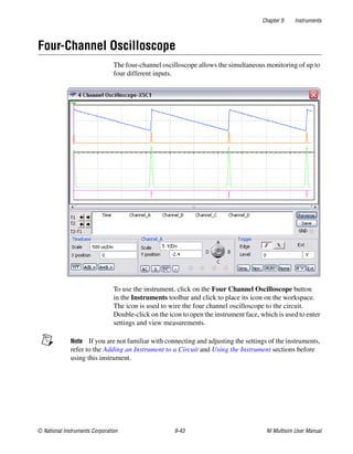
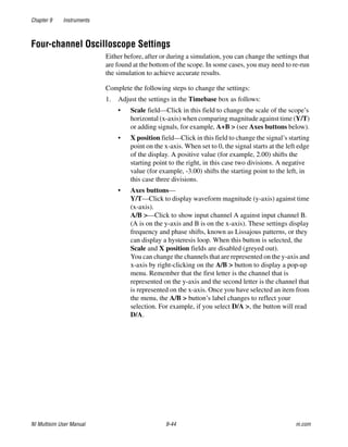
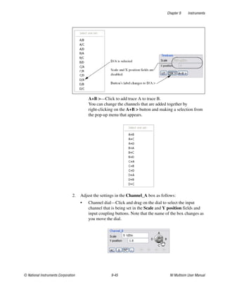
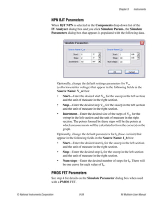
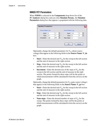
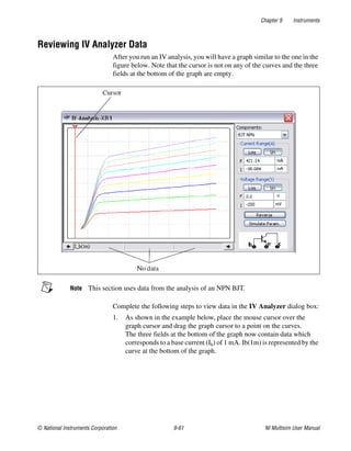
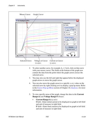
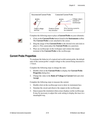
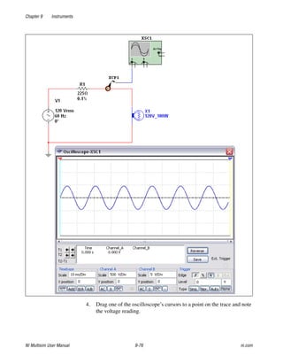
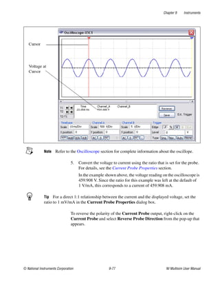
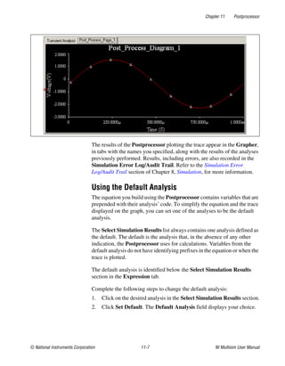
Download to read offline


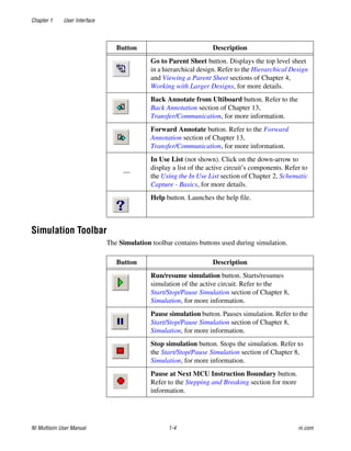
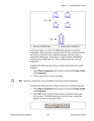
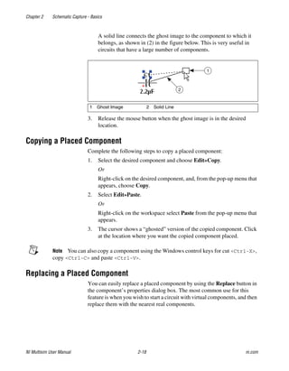
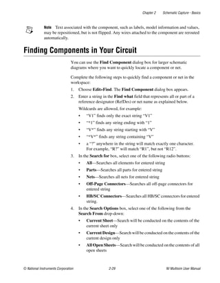
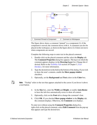
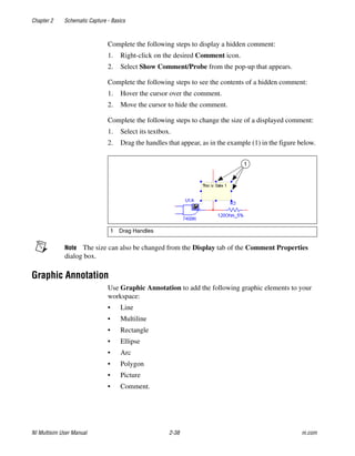
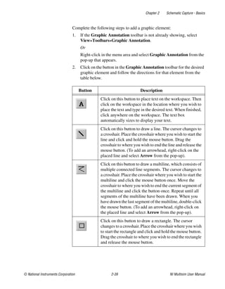
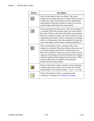
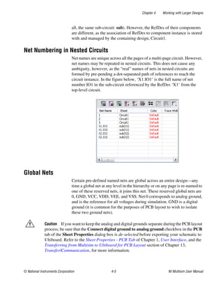
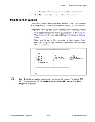
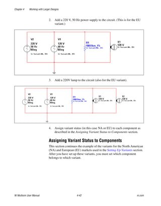
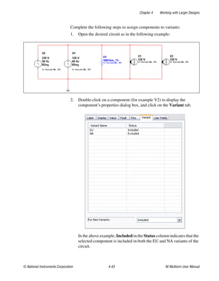

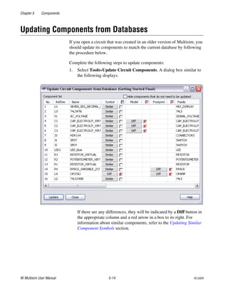
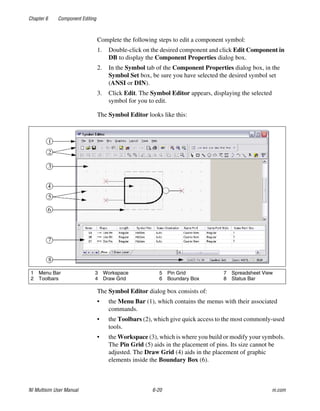
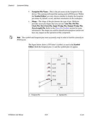
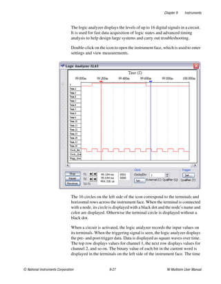
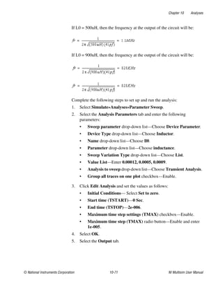
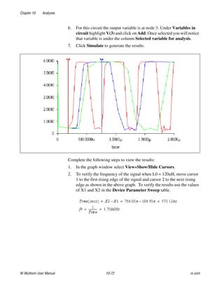
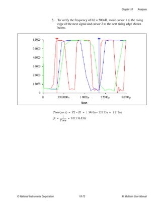
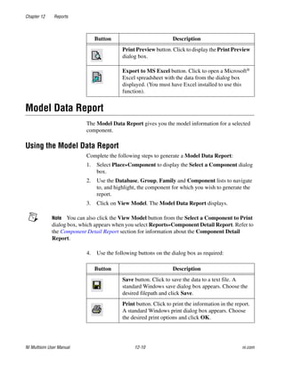
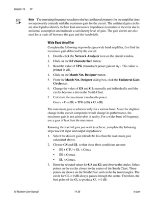
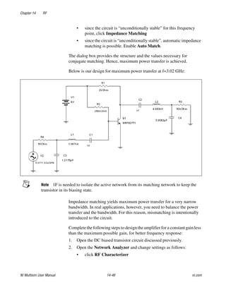
![Chapter 6 Component Editing
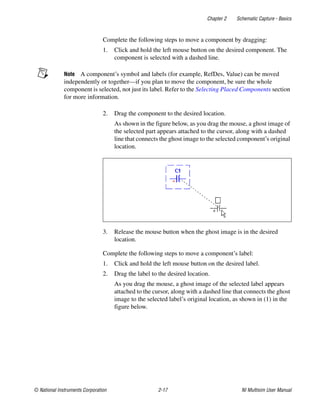
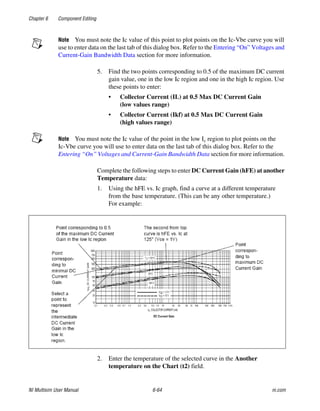
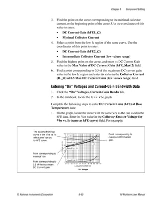
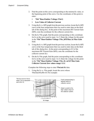
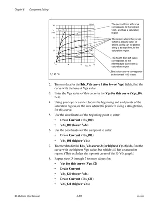
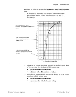
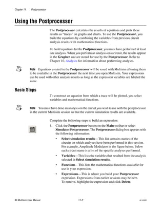
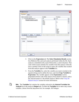
© National Instruments Corporation 6-3 NI Multisim User Manual
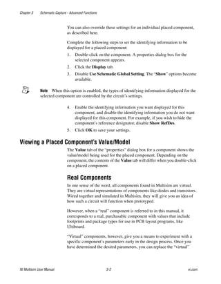
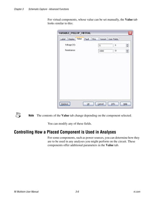
Tip You can also edit components that you have already placed on the workspace. This
can be done using the component’s properties dialog box (double-click on the component
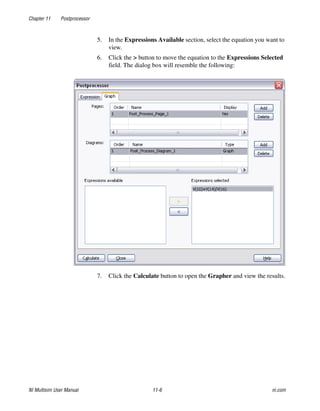
to display) and changing parameters in the various tabs. Changes made to placed
components in this manner will not be reflected in the database. If you place the same
component from the database, it will contain the parameters that it had before it was edited.
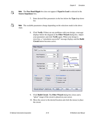
Edits to individual components can also be made via the Spreadsheet View.
Creating Components with the Component Wizard
Multisim includes a Component Wizard that quickly steps you through
the process of creating a component for use in schematic capture, as well
as simulation or layout, or both.
Creating an Analog Component
Analog parts such as diodes and transistors can be created following the
procedure in this section.
You can also create resistors, inductors and capacitors. However, resistors,
inductors and capacitors created using this procedure will only contain
basic simulation model information. Those that are placed from the master
database have additional temperature-related SPICE simulation
parameters. Refer to the Placing Resistors, Inductors or Capacitors section
of Chapter 2, Schematic Capture - Basics, for more information.
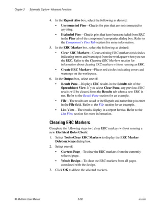
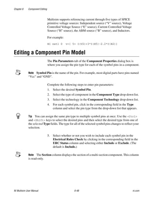
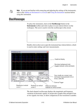
Complete the following steps to create an analog component:
1. Click the Create Component button in the Main toolbar.
Or
Choose Tools»Component Wizard. Step 1 of the Component
Wizard appears.
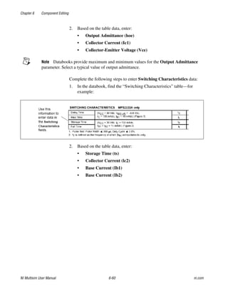
2. Complete the following:
• Component Name—The value of the component. Examples
include 10 ohms, 2N2221, 2uF. This field can only contain letters,
numbers, and the following characters: -+!@#$%^&()[]{}:
• Author Name—Completed by system; change if desired.
• Function—A brief description of the component. This is useful
because you can search the function field when looking for a
specific type of component to place.
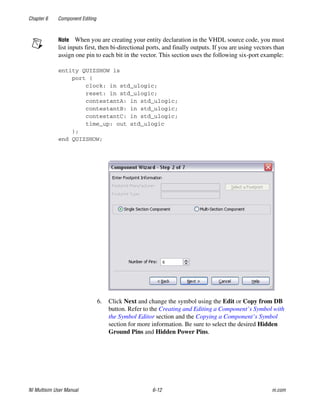
3. Select Analog from the Component Type drop-down list.](https://image.slidesharecdn.com/multisiminstructionmanual-240325152730-ba290443/85/Multisim-Instruction-Manual-Electric-circuits-230-320.jpg)
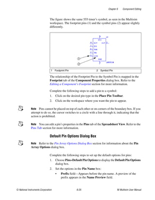
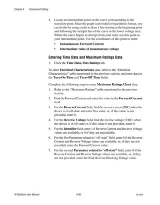
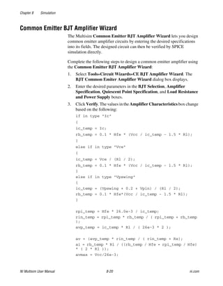
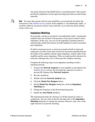
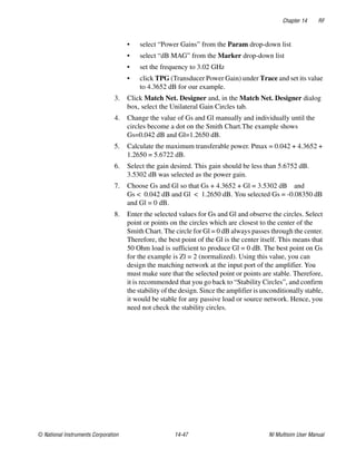
![Chapter 6 Component Editing
© National Instruments Corporation 6-7 NI Multisim User Manual
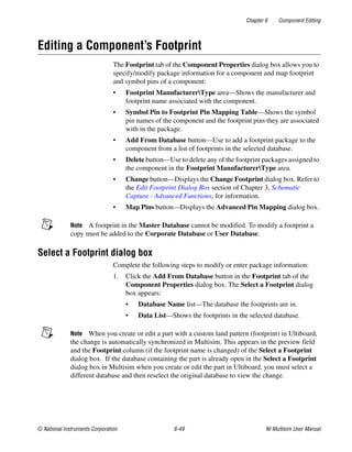
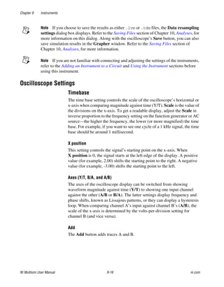
14. Click Next to display the next step, where you set mapping
information between the symbol and the simulation model. (This is for
parts with simulation models only.)
• For each symbol pin enter a corresponding number to connect to
its respective nodes in the model. The mapping information you
enter here will be displayed in the Model tab of the
Component Properties dialog box.
If you are creating a basic resistor, inductor or capacitor, this dialog
includes the following:
• SPICE Model Type drop-down list—Select one of: Resistor(r);
Capacitor(c); Inductor(l). The Value fields changes to reflect your
selection.
• Value fields—Enter the desired value, for example 100 uF.
Note A basic resistor, inductor or capacitor, created using the Component Wizard will
only contain basic simulation model information. Those that are placed from the master
database have additional temperature-related SPICE simulation parameters. Refer to the
Placing Resistors, Inductors or Capacitors section of Chapter 2, Schematic Capture -
Basics, for more information.
15. Click Next. The dialog box that appears lets you indicate where you
would like the component to be saved. If there is no family in the group
that you want to save the component, you can add a new family by
clicking on the Add Family button. Refer to the Managing Families
section of Chapter 5, Components, for more information.
16. Navigate to the family where you want to save the component and click
Finish. The component is saved in the selected family.
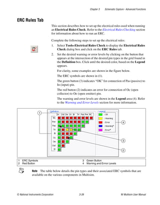
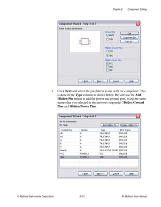
Creating a Digital Component
Complete the following steps to create a digital component:
1. Click the Create Component button in the Main toolbar.
Or
Choose Tools»Component Wizard. Step 1 of the Component
Wizard appears.
2. Complete the following as desired:
• Component Name—The value of the component, for example,
74ALS00M. This field can only contain letters, numbers, and the
following characters: -+!@#$%^&()[]{}:
• Author Name—Completed by system; change if desired.](https://image.slidesharecdn.com/multisiminstructionmanual-240325152730-ba290443/85/Multisim-Instruction-Manual-Electric-circuits-234-320.jpg)
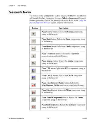
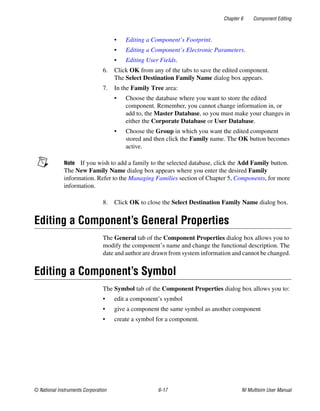
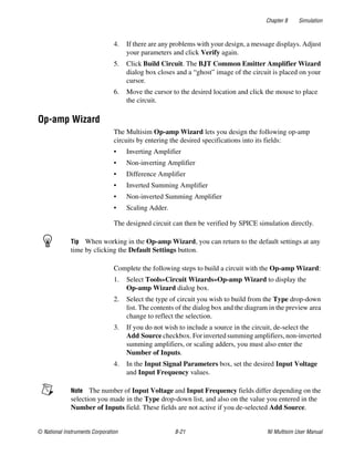
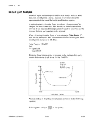
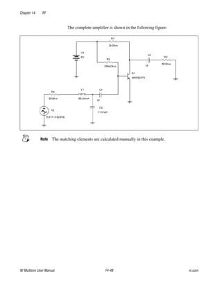
![Chapter 6 Component Editing
© National Instruments Corporation 6-11 NI Multisim User Manual
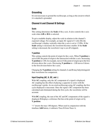
13. Click Next to display the next step, where you set mapping
information between the symbol and the simulation model.
• For each symbol pin enter a corresponding number to connect to
its respective nodes in the model. The mapping information you
enter here will be displayed in the Model tab of the
Component Properties dialog box.
14. Click Next. The dialog box that appears lets you indicate where you
would like the component to be saved. If there is no family in the group
that you want to save the component, you can add a new family by
clicking on the Add Family button. Refer to the Managing Families
section of Chapter 5, Components, for more information.
15. Navigate to the family where you want to save the component and click
Finish. The component is saved in the selected family.
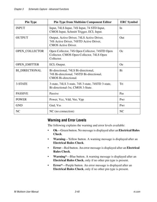
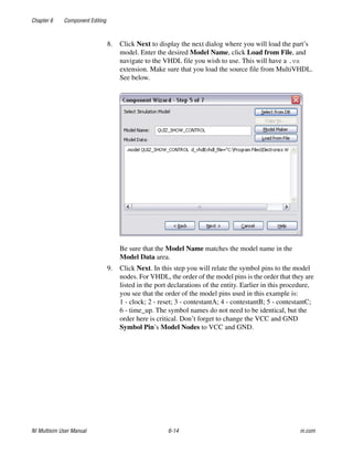
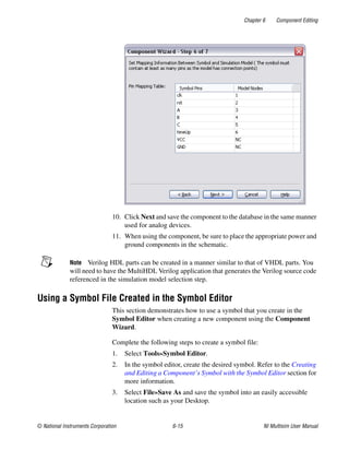
Creating a VHDL Component
The Component Wizard creates VHDL parts in a similar manner to
analog and digital components. For simplification, this section details
making a VHDL component for simulation only.
Complete the following steps to create a VHDL component:
1. Click the Create Component button in the Main toolbar.
Or
Choose Tools»Component Wizard. Step 1 of the Component
Wizard appears.
2. Complete the following:
• Component Name—The value of the component. This field can
only contain letters, numbers, and the following characters:
-+!@#$%^&()[]{}:
• Author Name—Completed by system; change if desired.
• Function—A brief description of the component.
3. Select VHDL from the Component Type drop-down list. The
Component Technology drop-down list appears with VHDL
selected.
4. For this example, select Simulation only (model) and click Next.
5. Set the number of pins to be equal to the number of ports you have in
the VHDL component. Don’t count power or ground, only count the
ports in the entity declaration.](https://image.slidesharecdn.com/multisiminstructionmanual-240325152730-ba290443/85/Multisim-Instruction-Manual-Electric-circuits-238-320.jpg)
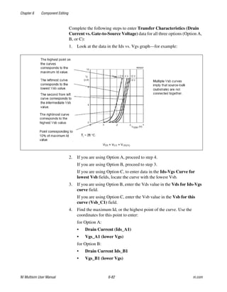
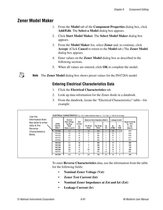
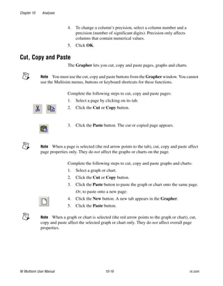
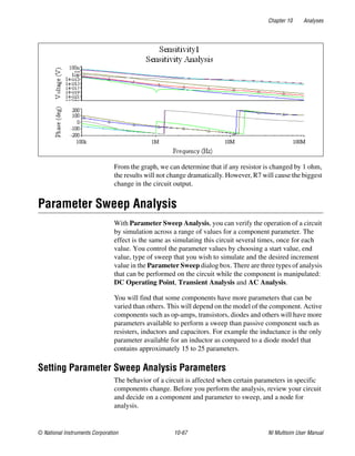
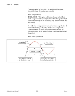
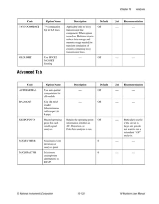
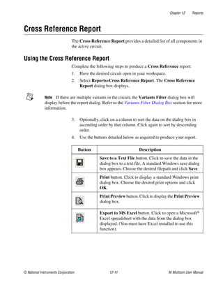
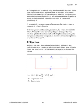
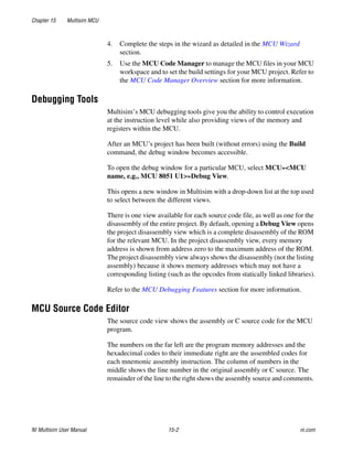
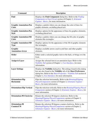
![Chapter 6 Component Editing
NI Multisim User Manual 6-86 ni.com
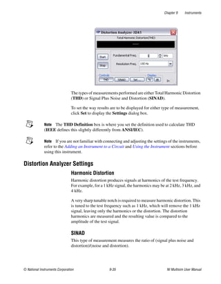
“Open-Loop Large Signal Differential Voltage”. If you use this chart, use the Avd value at
the lowest frequency.
Note Databooks provide Avd gain in either dB or V/mV. If the value is provided in V/mV,
you can still enter the data in dB. However, you should convert the numerical values:
value in dB = 20 * log[1000 * (value in V/mv)]
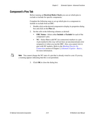
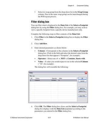
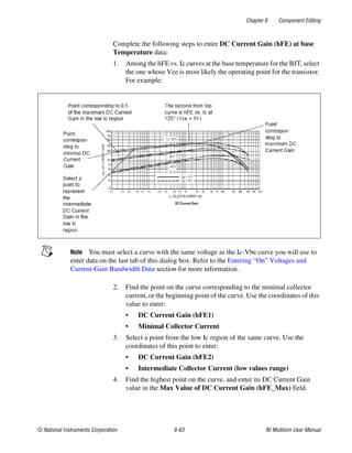
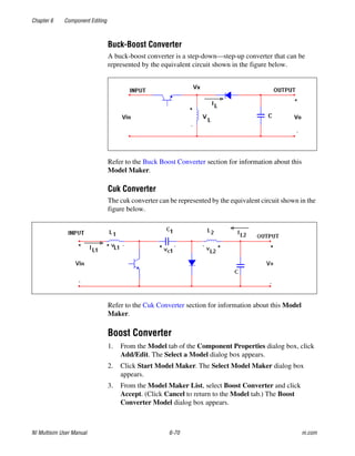
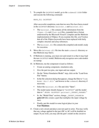
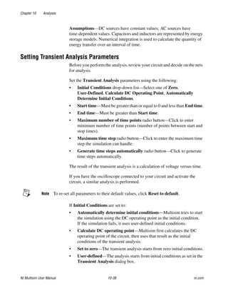
Entering Poles and Zero Data
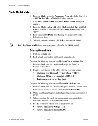
Complete the following steps to enter Gain-frequency curve poles and
Zero data:
1. Click the Gain frequency curve poles and Zero tab.
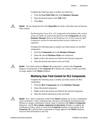
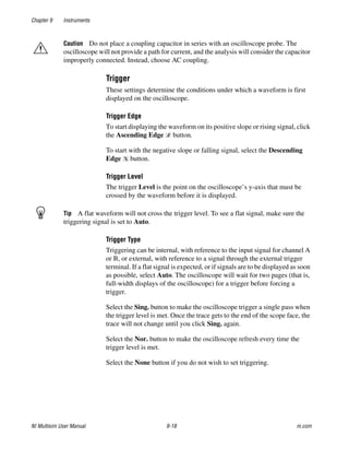
2. In the databook, locate the “Avd-Open-Loop Single Differential
Voltage Amplification vs. Frequency” chart—for example:
3. Find the first pole on the curve, or the point on the curve where the first
horizontal line transitions into a slope. Enter the frequency value for
this point in the Pole 1 frequency (fr1) field.
4. Find the second pole on the curve, or the point where the slope
transitions into a sharper slope. Enter the frequency value for this point
in the Pole 2 frequency (fr2) field.
To enter High frequency pole and zero data, find higher frequency poles
using the curve mentioned above, web sites or books. If these pieces of
information are not available, enable Not Available.](https://image.slidesharecdn.com/multisiminstructionmanual-240325152730-ba290443/85/Multisim-Instruction-Manual-Electric-circuits-313-320.jpg)
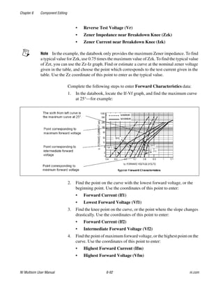
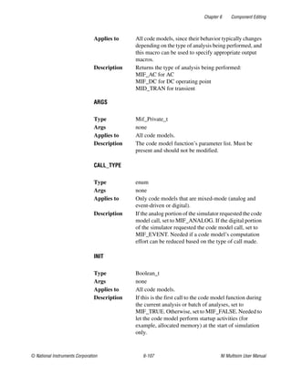
![Chapter 6 Component Editing
© National Instruments Corporation 6-95 NI Multisim User Manual
A code model consists of a set of interface definitions and a C function
implementation describing the device’s behavior. The naming and location
of these files is important. The model is created by combining two files
(Ifspec.ifs and Cfunc.mod). The resulting file, which is given the same
name as the folder containing its source files, is placed in the codemodl
folder.
Creating a Code Model
Refer to the GAINTEST Example section for a specific example of
compiling and using a code mode.
For best results, do all of the following steps from a DOS command
window.
Complete the following steps to create a code model:
1. Set up your environment variables for Microsoft Visual C++ by
running VcVars32.bat (installed, by default, in the C:/Program
Files/Microsoft Visual Studio/Vc98/Bin folder).
2. Navigate to C:Documents and SettingsAll Users
Shared DocumentsNational InstrumentsCircuit Design
Suite 10.1codemodl.
Note For systems using the Windows Vista operating system, the path is C:users
PublicDocumentsNational InstrumentsCircuit Design Suite 10.1
codemodl.
Within this directory is a single subdirectory called USER. You should
create new subdirectories inside of USER, one for each of your code
models. The name of the subdirectory will end up being the name of
the code model executable.
3. Create a new interface file inside your model’s subdirectory called
Ifspec.ifs to set up your model’s basic definitions and interface
(i/o ports and parameters).
4. Create a new implementation file inside your model’s subdirectory
called Cfunc.mod. This file contains the actual code model.
It is critical that the Cfunc.mod file include a list of all models in the
file in the following format:
SPICEdev * FAR DynDEVices[] = {
&<function_name>_info
};](https://image.slidesharecdn.com/multisiminstructionmanual-240325152730-ba290443/85/Multisim-Instruction-Manual-Electric-circuits-322-320.jpg)
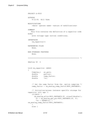
![Chapter 6 Component Editing
© National Instruments Corporation 6-97 NI Multisim User Manual
GAINTEST Example
The GAINTEST example is included in the Multisim install. This example
assumes familiarity with the Component Wizard.
1. Set up your environment variables for Microsoft Visual C++ by
running VcVars32.bat (installed, by default, in the C:/Program
Files/Microsoft Visual Studio/Vc98/Bin folder).
2. Navigate to C:Documents and SettingsAll Users
Shared DocumentsNational InstrumentsCircuit Design
Suite 10.1codemodlUSERGAINTEST. Notice that it contains
only two files: Ifspec.ifs and Cfunc.mod.
Note For systems using the Windows Vista operating system, the path is C:users
PublicDocumentsNational InstrumentsCircuit Design Suite 10.1
codemodlUSERGAINTEST.
3. If you wish, you may examine the Ifspec.ifs file for the GAINTEST
model. This defines many of the important characteristics of the
GAINTEST model:
• The C_Function_Name (cm_gaintest)
• The Spice_Model_Name (gaintest)
• One input port (analog: voltage, differential voltage, current, or
differential current).
• One output port (same options as the input).
4. Three model parameters (in_offset, gain, and out_offset).
Note that each parameter is given a plaintext description, a data type,
and a default value. All three of them have Null_Allowed defined as
“yes”, so they are all optional parameters. If any of these parameters
are omitted when calling the model, the default value will be used.
5. If you wish, you may examine the Cfunc.mod file for the GAINTEST
model. This file contains the actual code model – a simple C language
function with the same name defined as C_Function_Name in the
Ifspec.ifs file. Note use of XSpice keywords such as INPUT,
OUTPUT, PARAM, PARTIAL, and AC_GAIN. Note also the use of the
model parameters defined in the Ifspec.ifs file.
6. Note that the GAINTEST Cfunc.mod file includes the following:
SPICEdev * FAR DynDEVices[] = {
&cm_gaintest_info
};
as required by Multisim.](https://image.slidesharecdn.com/multisiminstructionmanual-240325152730-ba290443/85/Multisim-Instruction-Manual-Electric-circuits-324-320.jpg)
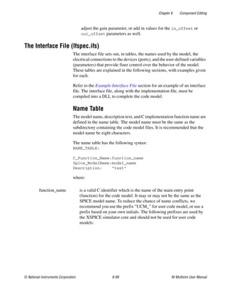
![Chapter 6 Component Editing
© National Instruments Corporation 6-101 NI Multisim User Manual
Description: “Capacitor with voltage initial
condition”
Port Table
The device ports are defined in the port tables. The port table has the
following syntax:
PORT_TABLE:
Port_Name: name
Description: text
Default_Type: default
Allowed_Type: [type type type]
Vector: vector
Vector_Bounds: size
Direction: dataflow
Null_Allowed: null
where:
name is a valid SPICE identifier giving the name of the port.
text is a string describing the purpose and function of the port.
default specifies the type used for the port when no type is explicitly
specified. Must be one of the items listed in “type”.
type lists the allowed types to which the port can be connected,
with names separated by commas or spaces (for example,
[d, g, h].
Type Name Valid Directions Description
d in, out digital
g in, out resistance (current
input, voltage
output)
in, out differential
conductance
(voltage input,
current output)
conductance
(voltage input,
current output)
gd in, out
h](https://image.slidesharecdn.com/multisiminstructionmanual-240325152730-ba290443/85/Multisim-Instruction-Manual-Electric-circuits-328-320.jpg)
![Chapter 6 Component Editing
NI Multisim User Manual 6-102 ni.com
For example:
PORT_TABLE:
Port_Name: cap
Description: “capacitor terminals”
Direction: inout
Default_Type: hd
Allowed_Types: [hd]
Vector: no
Vector_Bounds: -
Null_Allowed: no
hd in, out differential
resistance (current
input, voltage
output)
i in, out current
id in, out differential current
v in, out voltage
vd in, out differential voltage
vector specifies whether or not port is a vector and can be
considered a bus. Choose from:
- yes - this port is a vector
- no - this port is not a vector
size for port that are vectors only, specifies upper and lower
bounds on vector size. Lower bound specifies minimum
number of elements, upper bound specifies maximum
number of elements. For unconstrained range, or ports that
are not a vector, use a hyphen (“-”)
dataflow specifies the dataflow direction through the port. Choose
from:
- in
- out
- inout
null specifies whether or not it is an error to leave the port
unconnected. Choose from:
- yes - this port may be left unconnected
- no - this port must be connected](https://image.slidesharecdn.com/multisiminstructionmanual-240325152730-ba290443/85/Multisim-Instruction-Manual-Electric-circuits-329-320.jpg)
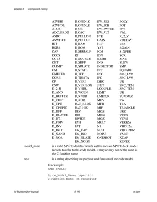
![Chapter 6 Component Editing
© National Instruments Corporation 6-105 NI Multisim User Manual
SUMMARY
This file contains the definition of a capacitor code
model with voltage type initial conditions.
INTERFACES
None.
REFERENCED FILES
None.
NON-STANDARD FEATURES
None.
==================================================== */
NAME_TABLE:
Spice_Model_Name: capacitor
C_Function_Name: cm_capacitor
Description: “Capacitor with voltage initial
condition”
PORT_TABLE:
Port_Name: cap
Description: “capacitor terminals”
Direction: inout
Default_Type: hd
Allowed_Types: [hd]
Vector: no
Vector_Bounds: -
Null_Allowed: no
PARAMETER_TABLE:
Parameter_Name: c ic
Description: “capacitance” “voltage initial
condition”
Data_Type: real real
Default_Value: - 0.0
Limits: - -
Vector: no no
Vector_Bounds: - -
Null_Allowed: no no](https://image.slidesharecdn.com/multisiminstructionmanual-240325152730-ba290443/85/Multisim-Instruction-Manual-Electric-circuits-332-320.jpg)
![Chapter 6 Component Editing
NI Multisim User Manual 6-106 ni.com
The Implementation File (Cfunc.mod)
At each simulation iteration for a circuit using the code model, Multisim’s
XSpice simulation engine calls the implementation file. An example of an
implementation file is shown in the Example Implementation File section.
The implementation file, along with the interface file, needs to be coupled
into a DLL to complete the code model.
The code model function then generates the code-modeled device’s output.
This output is based on the following:
• The input that XSpice presents to the code model function.
• The state of the model, which is stored and returned by XSpice.
The implementation file includes one or more of the macros, shown in the
Implementation File C Macros section, that provide the API (Application
Programming Interface) between XSpice and the code model.
This section lists the macros from which you can select. The example file
shown in the Example Implementation File section gives an example of
how to implement a macro. The implementation file, along with the
interface file, needs to be compiled into a DLL to complete the code model.
Implementation File C Macros
AC_GAIN(outputname, inputname)
ANALYSIS
Type Complex_t
Args y[i], x[i]
Applies to Analog code models only (event-driven or digital code
models should do nothing during AC analysis).
Description Assigns a value to this macro to specify the gain from
outputname to inputname at the current frequency. The
code model function is called once for each frequency
point simulated.
Type enum
Args none](https://image.slidesharecdn.com/multisiminstructionmanual-240325152730-ba290443/85/Multisim-Instruction-Manual-Electric-circuits-333-320.jpg)
![Chapter 6 Component Editing
NI Multisim User Manual 6-108 ni.com
INPUT(inputname)
INPUT_STATE(inputname)
INPUT_STRENGTH(inputname)
INPUT_TYPE(inputname)
Type double or void *
Args name [i]
Applies to Analog/mixed-mode code models.
Description Only analog inputs are allowed (for event-driven, use
INPUT_STATE and INPUT_STRENGTH). Returns
the value on the node or branch connected to
inputname. Type/units of input value is specified when
input type is specified in the Ifspec.Ifs file.
Type enum
Args name [i]
Applies to Digital/mixed-mode code models.
Description Only event-driven/digital inputs are allowed (for
analog, use INPUT). Returns the digital value (ZERO,
ONE or UNKNOWN) at node at inputname. When a
single output is connected to that node, this will equal
the value of the last output event. When multiple
outputs are connected, conflict resolution is performed.
Type enum
Args name [i]
Applies to Digital/mixed-mode code models.
Description Only event-driven/digital inputs are allowed (for
analog, use INPUT). Returns the digital strength
(STRONG, RESISTIVE, HI_IMPEDANCE or
UNDETERMINED) of node at inputname. When a
single output is connected to that node, this will equal
the strength of the last output event. When multiple
outputs are connected, conflict resolution is performed.
Type char *
Args name [i]](https://image.slidesharecdn.com/multisiminstructionmanual-240325152730-ba290443/85/Multisim-Instruction-Manual-Electric-circuits-335-320.jpg)
![Chapter 6 Component Editing
© National Instruments Corporation 6-109 NI Multisim User Manual
LOAD(inputname)
MESSAGE(outputname)
OUTPUT(outputname)
Applies to All code models.
Description Any inputs allowed. Returns the type string (i.e.: “v” for
voltage, “i” for digital, “hd” for differential
conductance, etc.) which describes the current usage of
inputname. Needed to distinguish between “simulation
time” usage of an input or output with more than one
allowed type. For example, used for an input which has
allowed types [v, i] and behaves differently when the
input is voltage vs. current.
Type double
Args name [i]
Applies to Digital/mixed-mode code models.
Description Only event-driven/digital inputs are allowed. Assign a
value to LOAD to set the input load due to inputname
on the connected node. The load is given as a
capacitance (normalized to 1ohm resistance) which is
summed with all the other loads on the event-driven
node to yield the total delay of the node.
Type char *
Args name [i]
Applies to Digital/mixed-mode code models.
Description Only event-driven/digital outputs are allowed. A
message string to be placed on an event-driven node can
be assigned to MESSAGE. Allows a code model to
issue a message associated with a node.
Type double or void *
Args name [i]
Applies to Analog/mixed-mode code models.](https://image.slidesharecdn.com/multisiminstructionmanual-240325152730-ba290443/85/Multisim-Instruction-Manual-Electric-circuits-336-320.jpg)
![Chapter 6 Component Editing
NI Multisim User Manual 6-110 ni.com
OUTPUT_CHANGED(outputname)
OUTPUT_DELAY(outputname)
OUTPUT_STATE(outputname)
Description Only analog outputs are allowed (for event-driven, use
OUTPUT_STATE and OUTPUT_STRENGTH and
OUTPUT_DELAY). Assigns a value to the node or
branch connected to outputname. Type/units of output
value specified when output type is specified in the
Ifspec.Ifs file.
Type Boolean_t
Args name [i]
Applies to Digital/mixed-mode code models.
Description Only event-driven/digital inputs are allowed. Set to
MIF_TRUE by default. Assign MIF_FALSE to indicate
no change on that output. Allows the code model to
specify that the event-driven output did not change and
thereby speed up simulation.
Type none
Args double
Applies to Digital/mixed-mode code models.
Description Only event-driven/digital inputs are allowed
(for analog, use OUTPUT).
Sets the delay after which the transition event specified
by OUTPUT_STATE occurs.
Type none
Args Digital_State_t
Applies to Digital/mixed-mode code models.
Description Only event-driven/digital outputs are allowed
(for analog, use OUTPUT). Assigns the digital value
(ZERO, ONE or UNKNOWN) to node at outputname
by creating an event which is a transition to that value.
When a single output is connected to that node, this will
equal the value of the last output event. When multiple
outputs are connected, conflict resolution is performed.](https://image.slidesharecdn.com/multisiminstructionmanual-240325152730-ba290443/85/Multisim-Instruction-Manual-Electric-circuits-337-320.jpg)
![Chapter 6 Component Editing
© National Instruments Corporation 6-111 NI Multisim User Manual
OUTPUT_STRENGTH(outputname)
OUTPUT_TYPE(inputname)
PARAM(paramname)
PARAM_NULL(paramname)
Type none
Args Digital_State_t
Applies to Digital/mixed-mode code models.
Description Only event-driven/digital outputs are allowed
(for analog, use OUTPUT). Assigns the digital strength
(STRONG, RESISTIVE, HI_IMPEDANCE or
UNDETERMINED) at node at outputname. When a
single output is connected to that node, this will equal
the strength of the last output event. When multiple
outputs are connected, conflict resolution is performed.
Type char *
Args name [i]
Applies to Digital/mixed-mode code models.
Description Any output allowed. Returns the type string (i.e.: “v”
for voltage, “i” for digital, “hd” for differential
conductance, etc.) which describes the current usage of
outputname. Needed to distinguish between
“simulation time” usage of an input or output with more
than one allowed type. For example, used for an input
which has allowed types [v, i] and behaves differently
when the input is voltage vs. current.
Type CD
Args name [i]
Applies to Any code model.
Description Applies to all parameters. Returns the value
paramname. Needed to access model parameters
specified in the netlist.
Type Boolean_t
Args name [i]](https://image.slidesharecdn.com/multisiminstructionmanual-240325152730-ba290443/85/Multisim-Instruction-Manual-Electric-circuits-338-320.jpg)
![Chapter 6 Component Editing
NI Multisim User Manual 6-112 ni.com
PARAM_SIZE(paramname)
PARTIAL
PORT_NULL
PORT_SIZE
Applies to Only parameters allowed to be unspecified (Null
allowed in the param table of the Ifspec.Ifs file is yes).
Description Returns MIF_TRUE if paramname was not specified in
the netlist and MIF_FALSE if it was specified. Allows
the code model to tell if a parameter value equals its
default because the default value was actually specified.
Type int
Args name
Applies to Vector type parameters only.
Description Returns the number of elements in a vector type
parameter. Needed to iterate over the vector parameter
if the number of vector elements is not fixed.
Type double
Args y[i], x[i]
Applies to Analog/mixed-mode code models.
Description Partial derivative of output y with respect to input x.
Type Boolean_t
Args name[i]
Applies to Any code model.
Description Has this port been specified as unconnected?
Type int
Args name
Applies to Any code model.
Description Size of port vector.](https://image.slidesharecdn.com/multisiminstructionmanual-240325152730-ba290443/85/Multisim-Instruction-Manual-Electric-circuits-339-320.jpg)
![Chapter 6 Component Editing
© National Instruments Corporation 6-113 NI Multisim User Manual
RAD_FREQ
T (<n>)
TEMPERATURE
TIME
Example Implementation File
Here is an example implementation file:
/* ====================================================
FILE cfunc.mod
MEMBER OF process XSPICE
Copyright 1991
Georgia Tech Research Corporation
Atlanta, Georgia 30332
All Rights Reserved
Type double
Args <none>
Applies to Analog/mixed-mode code models.
Description Current analysis frequency in radians per second.
Type double
Args <none>
Applies to All code models.
Description History of the previous nth analysis time (TIME =
T[0]). Maximum of 8.
Type double
Args <none>
Applies to All code models.
Description Current analysis temperature.
Type double
Args <none>
Applies to All code models.
Description Current analysis time (same as T[0]).](https://image.slidesharecdn.com/multisiminstructionmanual-240325152730-ba290443/85/Multisim-Instruction-Manual-Electric-circuits-340-320.jpg)
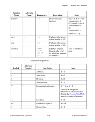
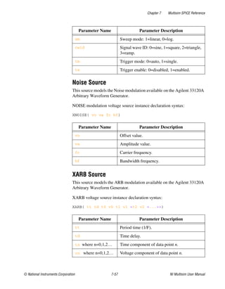
![Chapter 7 Multisim SPICE Reference
NI Multisim User Manual 7-2 ni.com
General Purpose Syntax
This section describes the overall syntax and building blocks of SPICE
models.
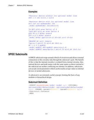
Primitive Device Declarations
SPICE Subcircuits
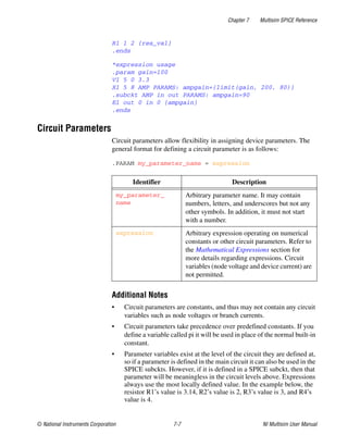
Circuit Parameters
Number Format
Comments and Line Continuation
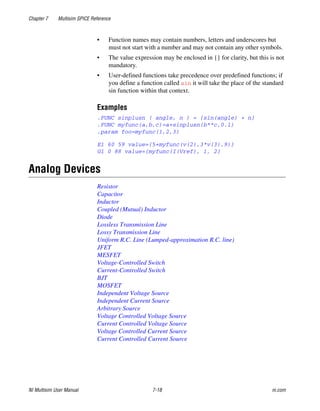
Primitive Device Declarations
A primitive device is the lowest level model that can be used in a circuit
and is a building block for macromodels and entire circuits. Multisim
supports many such devices. Refer to the Analog Devices section for more
information.
This section looks at how a primitive device is declared and used in a
circuit.
Primitive devices are comprised of either just an instance declaration or an
instance declaration with an associated model definition.
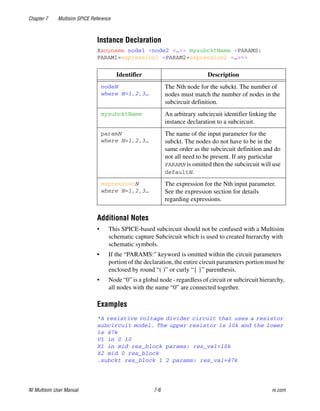
Instance Declaration
The instance declaration places a primitive device between circuit nodes,
specifies device parameters, and links the instance to a model definition
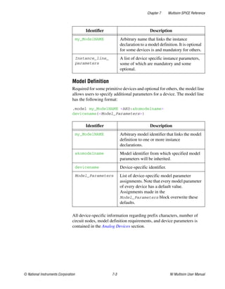
(where needed). The instance declaration has the following general format:
PREFIX_anyname node1 <node2 <…>> my_ModelNAME
Instance_line_parameters
Identifier Description
PREFIX Device specific character.
_anyname Arbitrary instance name suffix.
nodeN
where N=1,2,3…
The name of the Nth node that the device is
connected to. Node names may contain any
characters except for white space and the
following: {} () [] : # " ' ; , % <
> ` & = *](https://image.slidesharecdn.com/multisiminstructionmanual-240325152730-ba290443/85/Multisim-Instruction-Manual-Electric-circuits-344-320.jpg)
![Chapter 7 Multisim SPICE Reference
© National Instruments Corporation 7-19 NI Multisim User Manual
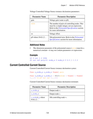
Resistor
Resistor instance declaration syntax:
Rxxxx node1 node2 resistance <TC=tc1 <,tc2> >
<TEMP=temp>
Rxxxx node1 node2 resistance <TC1=tc1> <TC2=tc2>
<TEMP=temp>
Rxxxx node1 node2 <resistance> <Model> <L=l> <W=w>
Resistor instance declaration parameters:
The following only applies if a model has been specified in the instance
declaration as it is not mandatory for resistors.
Resistor model definition syntax:
.MODEL mymodelname R ( <TC1=tc1 <TC2=tc2>>
<Other_Model_Parameters…> )
.MODEL mymodelname RES ( <TC1=tc1 < TC2=tc2>>
<Other_Model_Parameters…> )
Parameter Name Parameter Description
resistance Device resistance.
L Device length.
W Device width.
TC Instance temperature coefficients. This is a
two element vector for specifying TC1 and
TC2.
TC1 Alternate way of specifying 1st-order
temperature coefficient.
TC2 Alternate way of specifying 2nd-order
temperature coefficient.
SENS_RESIST [FLAG] Flag to request sensitivity with
respect to resistance.
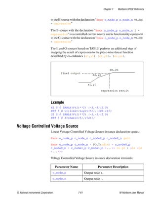
TEMP Instance operating temperature.](https://image.slidesharecdn.com/multisiminstructionmanual-240325152730-ba290443/85/Multisim-Instruction-Manual-Electric-circuits-361-320.jpg)
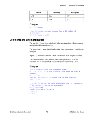
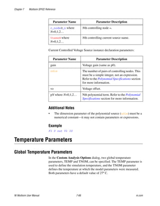
![Chapter 7 Multisim SPICE Reference
© National Instruments Corporation 7-21 NI Multisim User Manual
Capacitance instance declaration parameters:
The following only applies if a model has been specified in the instance
declaration as it is not mandatory for capacitors.
Capacitor model definition syntax:
.MODEL mymodelname C ( <TC1=tc1 <TC2=tc2>> <VC1=vc1
<VC2=vc2>> + <Other_Model_Parameters…> )
Capacitor model definition parameters:
Parameter Name Parameter Description
capacitance Device capacitance.
IC Initial capacitor voltage.
TC Instance temperature coefficients. This is a
two element vector for specifying TC1 and
TC2.
L Device length.
W Device width.
SENS_CAP [FLAG] Flag to request sensitivity with
respect to capacitance.
TEMP Instance temperature.
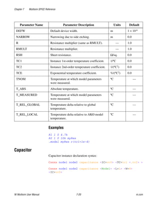
Parameter Name Parameter Description Units Default
CJ Junction bottom capacitance per area. F/(m2) 0.0
CJSW Junction sidewall capacitance per meter. F/m 0.0
CMULT Capacitance multiplier. — 1.0
DEFW Default width. m 1x10⁻⁶
NARROW Narrowing due to side etching. m 0.0
TNOM Temperature at which model parameters
were measured.
ºC —
T_ABS Absolute temperature. ºC —](https://image.slidesharecdn.com/multisiminstructionmanual-240325152730-ba290443/85/Multisim-Instruction-Manual-Electric-circuits-363-320.jpg)
![Chapter 7 Multisim SPICE Reference
NI Multisim User Manual 7-22 ni.com
Examples
c1 1 0 1u
C2 1 0 1e-12 myCap
.model myCap C(tc1=1e-4)
Inductor
Inductor instance declaration syntax:
Lxxxx node1 node2 <Model> inductance <IC=iL0>
Inductor instance declaration parameters:
The following only applies if a model has been specified in the instance
declaration as it is not mandatory for inductor.
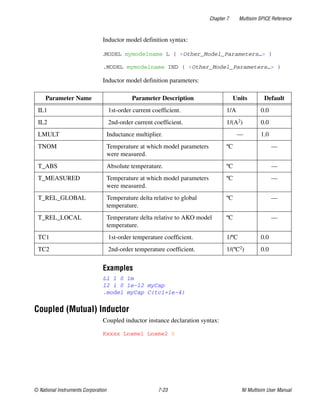
T_MEASURED Temperature at which model parameters
were measured.
ºC —
T_REL_GLOBAL Temperature delta relative to global
temperature.
ºC —
T_REL_LOCAL Temperature delta relative to AKO model
temperature.
ºC —
TC1 1st-order temperature coefficient. 1/ºC 0.0
TC2 2nd-order temperature coefficient. 1/(ºC2) 0.0
VC1 1st-order voltage coefficient. 1/V 0.0
VC2 2nd-order voltage coefficient. 1/(V2) 0.0
Parameter Name Parameter Description
inductance Device inductance.
IC Initial current through inductor.
SENS_IND [FLAG] Flag to request sensitivity with
respect to inductance.
TEMP Instance temperature.
Parameter Name Parameter Description Units Default](https://image.slidesharecdn.com/multisiminstructionmanual-240325152730-ba290443/85/Multisim-Instruction-Manual-Electric-circuits-364-320.jpg)
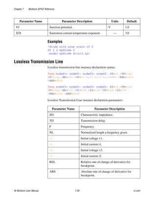
![Chapter 7 Multisim SPICE Reference
NI Multisim User Manual 7-28 ni.com
Example
O1 1 0 2 0 myLossyLine
.model myLossyLine LTRA(r=3.5 L=3m g=1e-6 c=3.2e-6)
Uniform R.C. Line (Lumped-approximation R.C. line)
Uniform R.C. line instance declaration syntax:
Uxxx node1 node2 nodeRef Model L=len <N=lumps>
REL Relative rate of change of derivative for
breakpoint.
— 1.0
ABS Absolute rate of change of derivative for
breakpoint.
— 1.0
NOCONTROL [FLAG] No timestep control. — —
STEPLIMIT [FLAG] Always limit timestep to 0.8*(delay
of line).
— —
NOSTEPLIMIT [FLAG] Don’t always limit timestep to
0.8*(delay of line).
— —
LININTERP [FLAG] Use linear interpolation. — —
QUADINTERP [FLAG] Use quadratic interpolation. — —
MIXEDINTERP [FLAG] Use linear interpolation if quadratic
results look unacceptable.
— —
TRUNCNR Use N-R iterations for step calculation in
LTRAtrunc.
— —
TRUNCDONTCUT Don’t limit timestep to keep impulse
response calculation errors low.
— —
COMPACTREL Special reltol for straight line checking. — —
COMPACTABS Special abstol for straight line checking. — —
Parameter Name Parameter Description Units Default](https://image.slidesharecdn.com/multisiminstructionmanual-240325152730-ba290443/85/Multisim-Instruction-Manual-Electric-circuits-370-320.jpg)
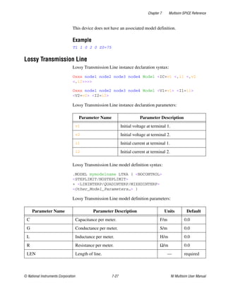
![Chapter 7 Multisim SPICE Reference
© National Instruments Corporation 7-29 NI Multisim User Manual
Uniform R.C. line instance declaration parameters:
Uniform R.C. line model definition syntax:
.MODEL mymodelname URC ( <Other_Model_Parameters…> )
Uniform R.C. line model definition parameters:
Example
U1 1 2 0 myURC
.model myURC URC(isperl=1e-9)
JFET
JFET instance declaration syntax:
Jxxx nodeDrain nodeGate nodeSource Model <area> <OFF>
<IC=vds0, vgs0>
JFET instance declaration parameters:
Parameter Name Parameter Description
L Length of transmission line.
N Number of lumps.
Parameter Name Parameter Description Units Default
CPERL Capacitance per unit length. F/m 1 × 10-12
FMAX Maximum frequency of interest. Hz 1 × 10⁹
ISPERL Saturation current per length. A/m —
K Propagation constant. — 1.5
RPERL Resistance per unit length. Ω/m 1000
RSPERL Diode resistance per length. Ω/m —
Parameter Name Parameter Description
area Area factor.
OFF [FLAG] Device is initially off.](https://image.slidesharecdn.com/multisiminstructionmanual-240325152730-ba290443/85/Multisim-Instruction-Manual-Electric-circuits-371-320.jpg)
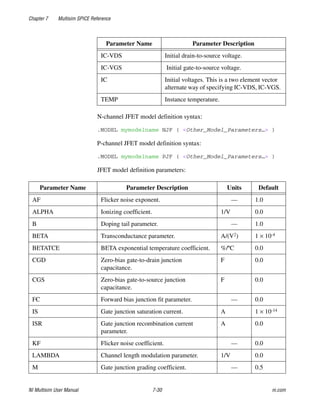
![Chapter 7 Multisim SPICE Reference
NI Multisim User Manual 7-32 ni.com
N-channel MESFET model definition syntax:
.MODEL mymodelname NMF ( <Other_Model_Parameters…> )
P-channel MESFET model definition syntax:
.MODEL mymodelname PMF ( <Other_Model_Parameters…> )
MESFET model definition parameters:
Parameter Name Parameter Description
area Area factor.
OFF [FLAG] Device is initially off.
ICVDS Initial drain-to-source voltage.
ICVGS Initial gate-to-source voltage.
TEMP Instance temperature.
Parameter Name Parameter Description Units Default
AF Flicker noise exponent. — 1.0
ALPHA Saturation voltage parameter. 1/V 2.0
B Doping tail parameter. — 0.3
BETA Transconductance parameter. A/(V2) 2.5 × 10⁻³
BETATCE BETA exponential temperature coefficient. %/ºC 0.0
CDS Drain-to-source junction capacitance. F 0.0
CGD Gate-to-drain junction capacitance. F 0.0
CGS Gate-to-source junction capacitance. F 0.0
EG Bandgap voltage. eV 1.11
FC Forward bias depletion capacitance
coefficient.
— 0.5
IS Junction saturation current. A 1 × 10-14
KF Flicker noise coefficient. — 0.0
LAMBDA Channel length modulation parameter. 1/V 0.0](https://image.slidesharecdn.com/multisiminstructionmanual-240325152730-ba290443/85/Multisim-Instruction-Manual-Electric-circuits-374-320.jpg)
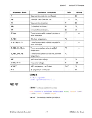
![Chapter 7 Multisim SPICE Reference
NI Multisim User Manual 7-34 ni.com
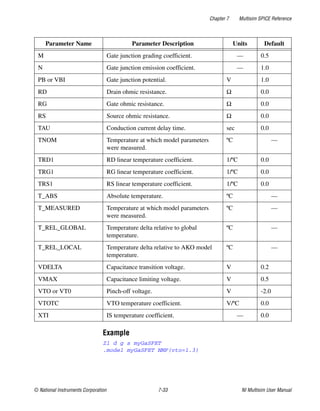
Voltage-Controlled Switch
Voltage-Controlled switch instance declaration syntax:
Sxxx node_n+ node_n- nodeNC+ nodeNC- Model <ON/OFF>
Voltage-Controlled Switch instance declaration parameters:
Voltage-Controlled Switch model definition syntax:
.MODEL mymodelname SW ( <Other_Model_Parameters…> )
Voltage-Controlled Switch model definition parameters:
Parameter Name Parameter Description
ON [FLAG] Switch initially closed.
OFF [FLAG] Switch initially open.
Parameter Name Parameter Description Units Default
ROFF Resistance when open. Ω 1/GMIN
RON Resistance when closed. Ω 1.0
VH Hysteresis voltage. V 0.0
VT Threshold voltage. V 0.0](https://image.slidesharecdn.com/multisiminstructionmanual-240325152730-ba290443/85/Multisim-Instruction-Manual-Electric-circuits-376-320.jpg)
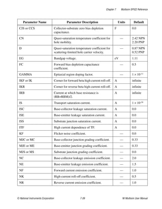
![Chapter 7 Multisim SPICE Reference
NI Multisim User Manual 7-38 ni.com
BJT instance declaration parameters:
BJT device NPN model definition syntax:
.MODEL mymodelname NPN (<Other_Model_Parameters…> )
BJT device PNP model definition syntax:
.MODEL mymodelname PNP (<Other_Model_Parameters…> )
BJT device LPNP model definition syntax:
.MODEL mymodelname LPNP (<Other_Model_Parameters…> )
BJT model definition parameters:
Parameter Name Parameter Description
area Area factor.
OFF [FLAG] Device is initially off.
ICVBE Initial base-emitter voltage.
ICVCE Initial collector-emitter voltage.
IC Initial voltages. This is a two element vector
alternate way of specifying ICVBE, ICVCE.
SENS_AREA [FLAG] Flag to request sensitivity with
respect to area.
TEMP Instance temperature.
Parameter Name Parameter Description Units Default
AF Flicker noise exponent. — 1.0
BF Ideal maximum forward beta. — 100.0
BR Ideal maximum reverse beta. — 1.0
CJC Base-collector zero bias depletion
capacitance.
F 0.0
CJE Base-emitter zero bias depletion
capacitance.
F 0.0](https://image.slidesharecdn.com/multisiminstructionmanual-240325152730-ba290443/85/Multisim-Instruction-Manual-Electric-circuits-380-320.jpg)
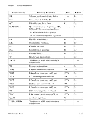
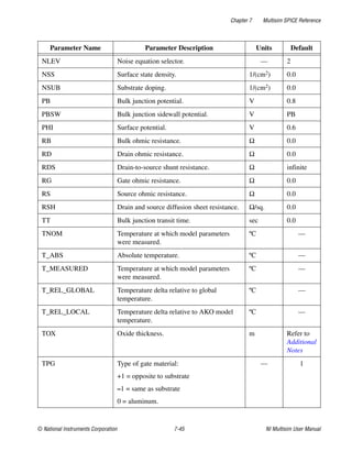
![Chapter 7 Multisim SPICE Reference
NI Multisim User Manual 7-42 ni.com
MOSFET
MOSFET device instance declaration syntax:
Mxxx nodeDrain nodeGate nodeSource nodeBulk Model
<<L=>l> <<W=>w> <AD=ad> <AS=as> <PD=pd> <PS=ps>
+ <NRD=nrd> <NRS=nrs> <M=m> <OFF> <IC=vds <, vgs <,
vbs>>>
Mxxx nodeDrain nodeGate nodeSource nodeBulk Model
<<L=>l> <<W=>w> <AD=ad> <AS=as> <PD=pd> <PS=ps>
+ <NRD=nrd> <NRS=nrs> <M=m> <OFF> <VDS=vds> <VGS=vgs>
<VBS=vbs>
Basic MOSFET instance declaration parameters:
Parameter Name Parameter Description
L Length.
W Width.
AD Drain area.
AS Source area.
PD Drain perimeter.
PS Source perimeter.
NRD Number of squares in drain.
NRS Number of squares in source.
M Device multiplicity factor.
OFF [FLAG] Device is initially off.
ICVDS Initial drain-to-source voltage.
ICVGS Initial gate-to-source voltage.
ICVBS Initial bulk-to-source voltage.
IC Initial voltages. This is a three element vector
alternate way of specifying ICVDS, ICVGS,
ICVBS.
SENS_L [FLAG] flag to request sensitivity with respect
to length.](https://image.slidesharecdn.com/multisiminstructionmanual-240325152730-ba290443/85/Multisim-Instruction-Manual-Electric-circuits-384-320.jpg)
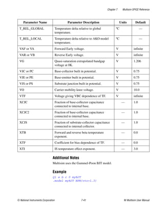
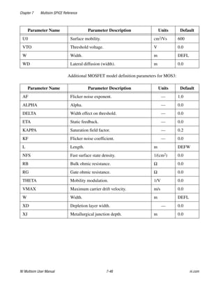
![Chapter 7 Multisim SPICE Reference
© National Instruments Corporation 7-43 NI Multisim User Manual
MOSFET device NMOS simulation model definition syntax:
.MODEL mymodelname NMOS (<LEVEL=level>
<Other_Model_Parameters…> )
MOSFET device PMOS simulation model definition syntax:
.MODEL mymodelname PMOS (<LEVEL=level>
<Other_Model_Parameters…> )
The LEVEL parameter is used to select the appropriate MOSFET
simulation model. Multisim provides eight different MOSFET models,
which are described below:
Depending on the Level value, different parameters for both instance
declarations and model definitions are available.
SENS_W [FLAG] flag to request sensitivity with respect
to width.
TEMP Instance temperature.
Level Value Description
1 or MOS1 Shichman-Hodges model (DEFAULT model).
2 or MOS2 More complex model than LEVEL 1 based on
actual device physics.
3 or MOS3 Semi-empirical model good for simulating
short channel effects.
4 or BSIM1 BSIM1.
5 or BSIM2 BSIM2.
6 or MOS6 N-th power law MOSFET model.
8 or BSIM3 BSIM3 (version 3v3).
14 or BSIM BSIM4 (version 4v5).
Parameter Name Parameter Description](https://image.slidesharecdn.com/multisiminstructionmanual-240325152730-ba290443/85/Multisim-Instruction-Manual-Electric-circuits-385-320.jpg)
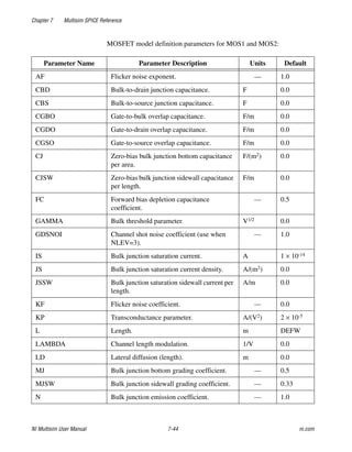
![Chapter 7 Multisim SPICE Reference
NI Multisim User Manual 7-68 ni.com
The Cadence® PSpice® temperature parameters (T_MEASURED, T_ABS,
T_REL_LOCAL, T_REL_GLOBAL) can only be set for the following
devices:
• Resistor
• Capacitor
• Inductor
• BJT
• JFET
• MESFET
• MOSFET (level 1, 2, and 3)
• Diode
When using these parameters a maximum of one device temperature
customization (T_ABS, T_REL_LOCAL, T_REL_GLOBAL) can coexist
with the T_MEASURED parameter.
Note The Cadence® PSpice® temperature parameters have precedence over the TEMP
instance and TNOM model parameters.
XSPICE Syntax Reference
XSPICE Code Model
XSPICE Code Model
XSPICE syntax for a terminal:
<%TerminalType> <(> nodename <, referencenodename> <)>
<%TerminalType> [ arraynodename1 <, arraynodename2 <,
...>> ]
XSPICE Terminal types:
Symbol Description
%D Digital terminal.
%V Voltage terminal.
%I Current terminal.
%G Voltage in/current out terminal.](https://image.slidesharecdn.com/multisiminstructionmanual-240325152730-ba290443/85/Multisim-Instruction-Manual-Electric-circuits-410-320.jpg)

![Chapter 11 Postprocessor
NI Multisim User Manual 11-12 ni.com
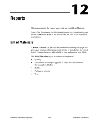
grpdelay(X)—Group delay of vector X in seconds, where:
integral(X)—Running integral of vector X, where:
mag(X)—Vector magnitude
ph(X)—Vector phase
norm(X)—Vector X normalized to 1 where:
rms(X)—Running RMS average of vector X where:
rnd(X)—Vector random
mean(X)—Vector results in a scalar (a length 1 vector) that is the mean of
the elements of the vector
Vector(n)—Vector results in a vector of length n, with elements 0, 1, ...
n-1. If n is a vector than just the first element is taken, and if it isn’t an
image then the floor of the magnitude is used
length(X)—Vector length of vector X
max(X)—Vector maximum value from X
min(X)—Vector minimum value from X
vm(X)—Vector vm(x) = mag(v(X))
vp(X)—Vector vp(x) = ph(v(X))
grpdelay X freq
( )
( )i
1
360
--------
-
–
d ph X freq
( )
( )
[ ]
dfreq
--------------------------------------
-
freqi
1
360
--------
-
– deriv ph X freq
( )
( )
[ ]freqi
= =
integral X xi
( )
( )i X x
( ) x
d
xo
xi
∫
=
norm X
( )
X
max abs X
( )
( )
--------------------------------
-
=
rms X xi
( )
( )i
X x
( )
2
x
d
xo
xi
∫
xi xo
–
--------------------------
-
=](https://image.slidesharecdn.com/multisiminstructionmanual-240325152730-ba290443/85/Multisim-Instruction-Manual-Electric-circuits-667-320.jpg)


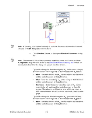
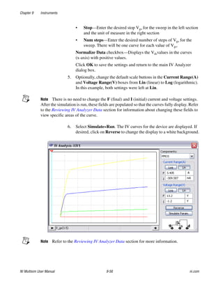
This document contains the user manual for NI Multisim. It includes sections on support and contact information, important information such as warranty and copyright, and conventions used in the manual. The manual provides information to help users understand and customize the interface, perform schematic capture basics such as placing components and wiring them, and add labels and annotations. It also describes preferences, sheet properties, and the design toolbox.