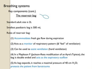
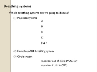
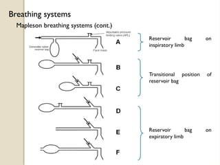
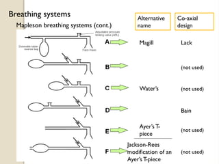
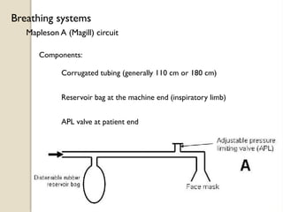
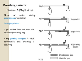
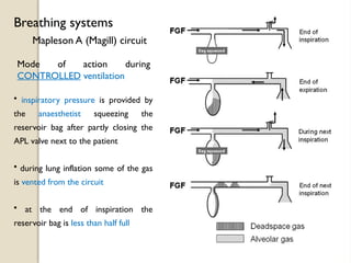
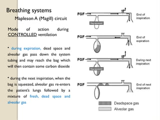
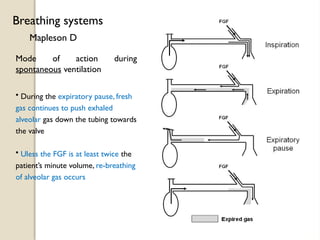
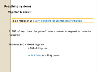
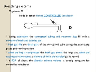
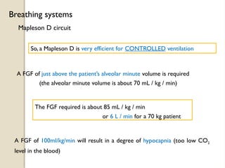
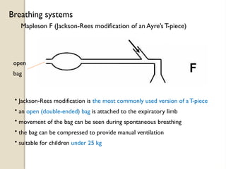
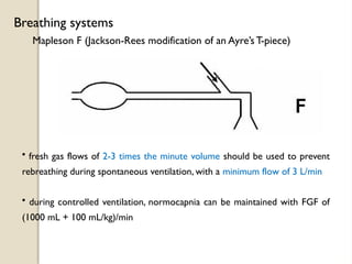
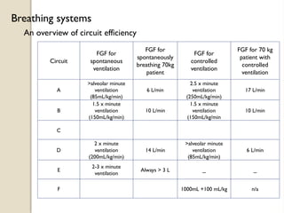
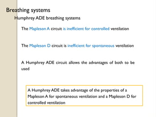
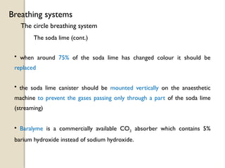
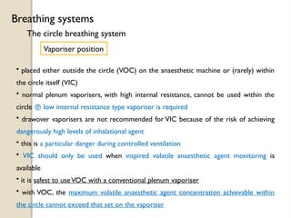
The document provides a comprehensive overview of various breathing systems used in anesthesia, detailing components, efficiencies, and considerations for ventilation. It includes discussions on Mapleson systems, rebreathing concepts, and the advantages of circle systems that recirculate gases to minimize waste. The objective is to inform anesthesiologists about system selection to optimize patient care and ventilation efficiency.

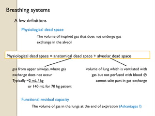
![A few definitions
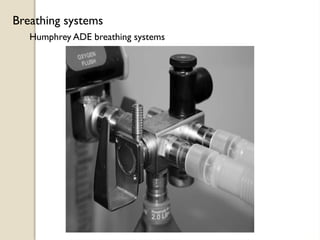
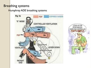
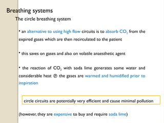
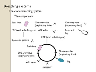
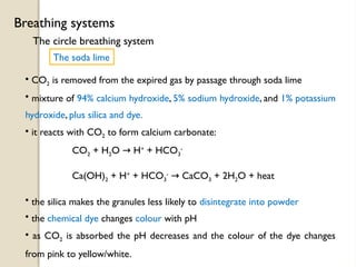
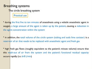
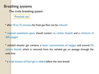
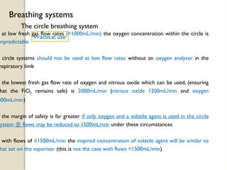
Breathing systems
Tidal volume
Minute volume
The volume of gas inspired & expired with each breath
Typically ≈7 mL / kg
(or 500 mL for 70 kg patient)
The total volume breathed in a minute
Typically ≈100 mL / kg / min
(or 7000 mL / min for 70 kg patient)
Alveolar minute volume
The volume undergoing gas exchange per minute
( = RR x [tidal vol – dead space] )
Typically ≈70 mL / kg / min
(or 5000 mL / min for 70 kg patient)](https://image.slidesharecdn.com/3-241124083054-444343e1/85/3-different-types-of-breathing-system-pptx-5-320.jpg)
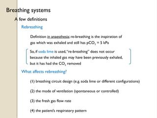
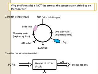
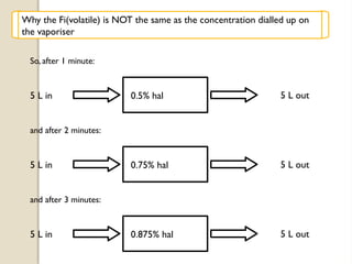
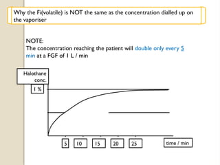
![5 L in 5 L out
5 L volume
Let the FGF = 5 L / min
and the circle circuit volume = 5 L
In one minute:
This is like diluting the circle circuit (5 L) with a further 5 L every minute
Suppose the dialed [halothane] = 1 % (the vaporiser setting)
5 L in
(1 % Hal)
5 L out
(0.5%Hal)
5 L volume + 5L
FGF
These are approximately
correct
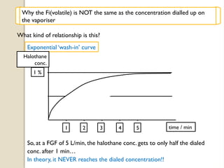
Why the Fi(volatile) is NOT the same as the concentration dialled up on
the vaporiser](https://image.slidesharecdn.com/3-241124083054-444343e1/85/3-different-types-of-breathing-system-pptx-53-320.jpg)


![CTEV [ clubfoot] DR ARUN LAL ,DR MOHAMED ASHRAF travancore medical college k...](https://cdn.slidesharecdn.com/ss_thumbnails/ctevclubfootdrarunlaldrmohamedashraftravancoremedicalcollegekollamkeralaindia-260208063247-18fc466c-thumbnail.jpg?width=640&height=640&fit=bounds)
![PERI-PROSTHETIC FRACTURE NAIL-PLATE CONSTRUCT [NPC].pptx](https://cdn.slidesharecdn.com/ss_thumbnails/drarunkumardrmohamedashrafperiprostheticfrasturenail-plateconstructnpc-260209164459-7e9d15a1-thumbnail.jpg?width=640&height=640&fit=bounds)

![ONFH[AVN HIP] -TRIPLE REGIME -A NOVAL SURGICAL CONCEPT .pptx](https://cdn.slidesharecdn.com/ss_thumbnails/onfhavnhip2026koaconcalicutdrgokuldevdrmashraf-260210064517-213ec005-thumbnail.jpg?width=640&height=640&fit=bounds)

