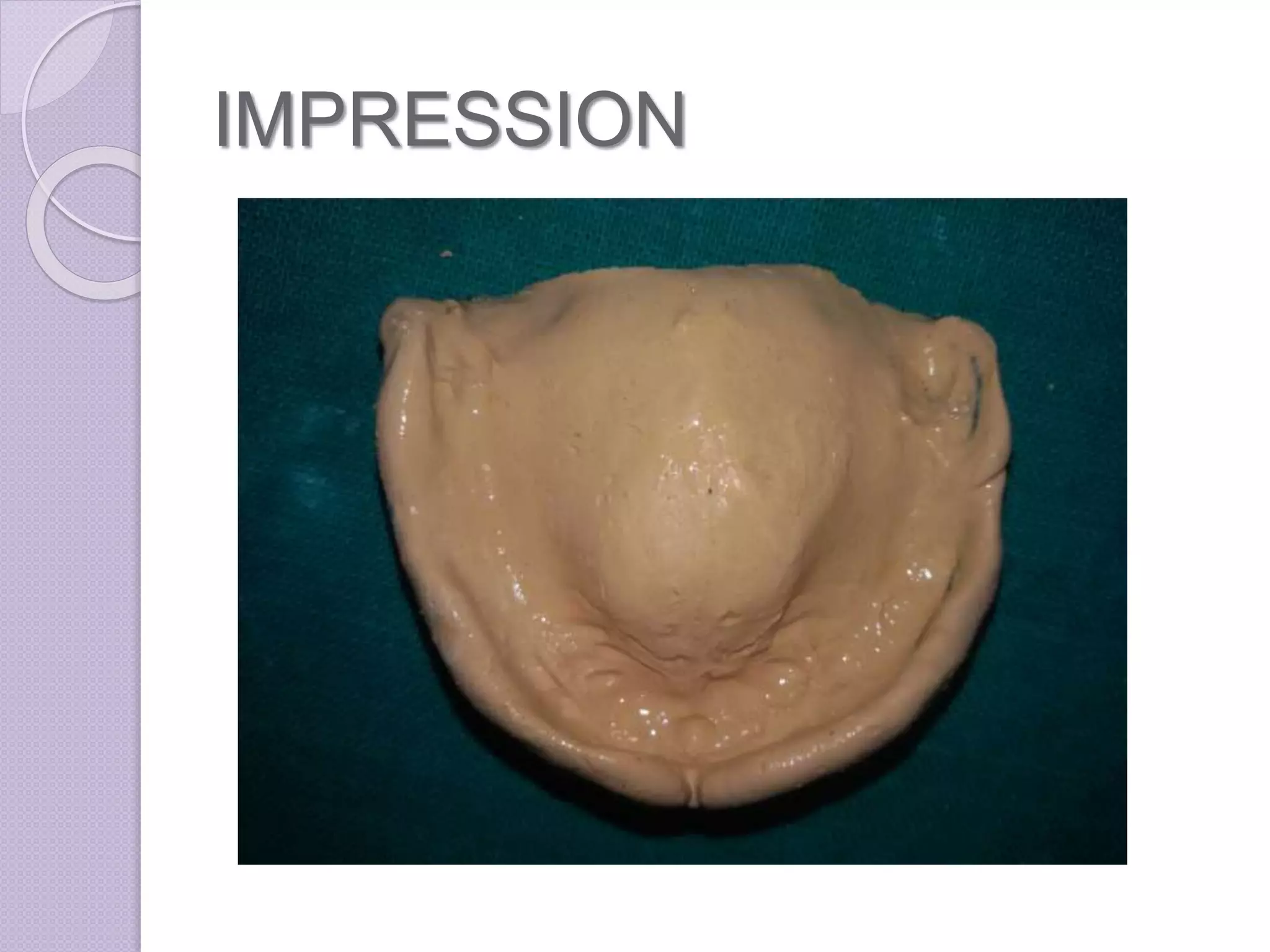
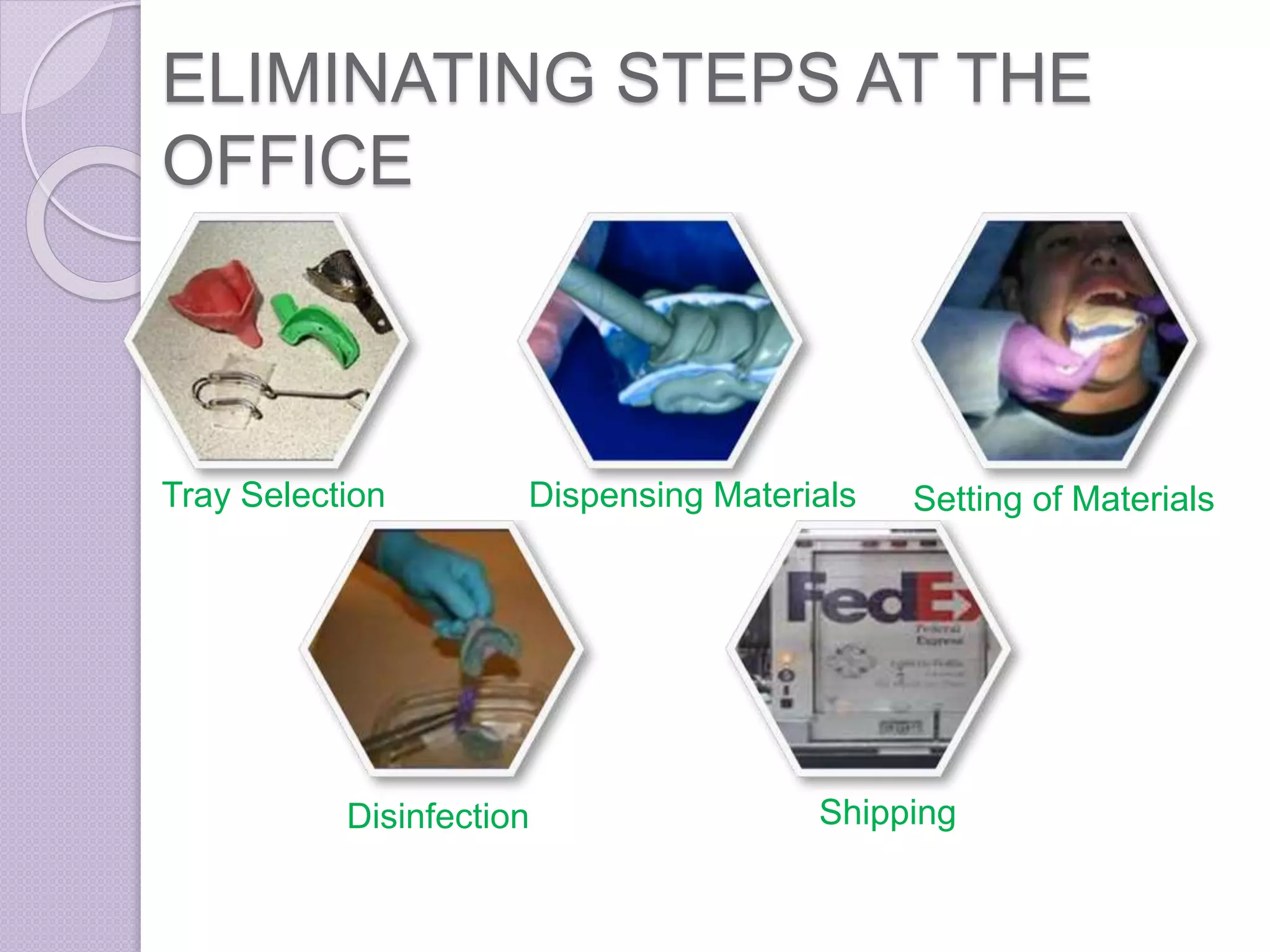
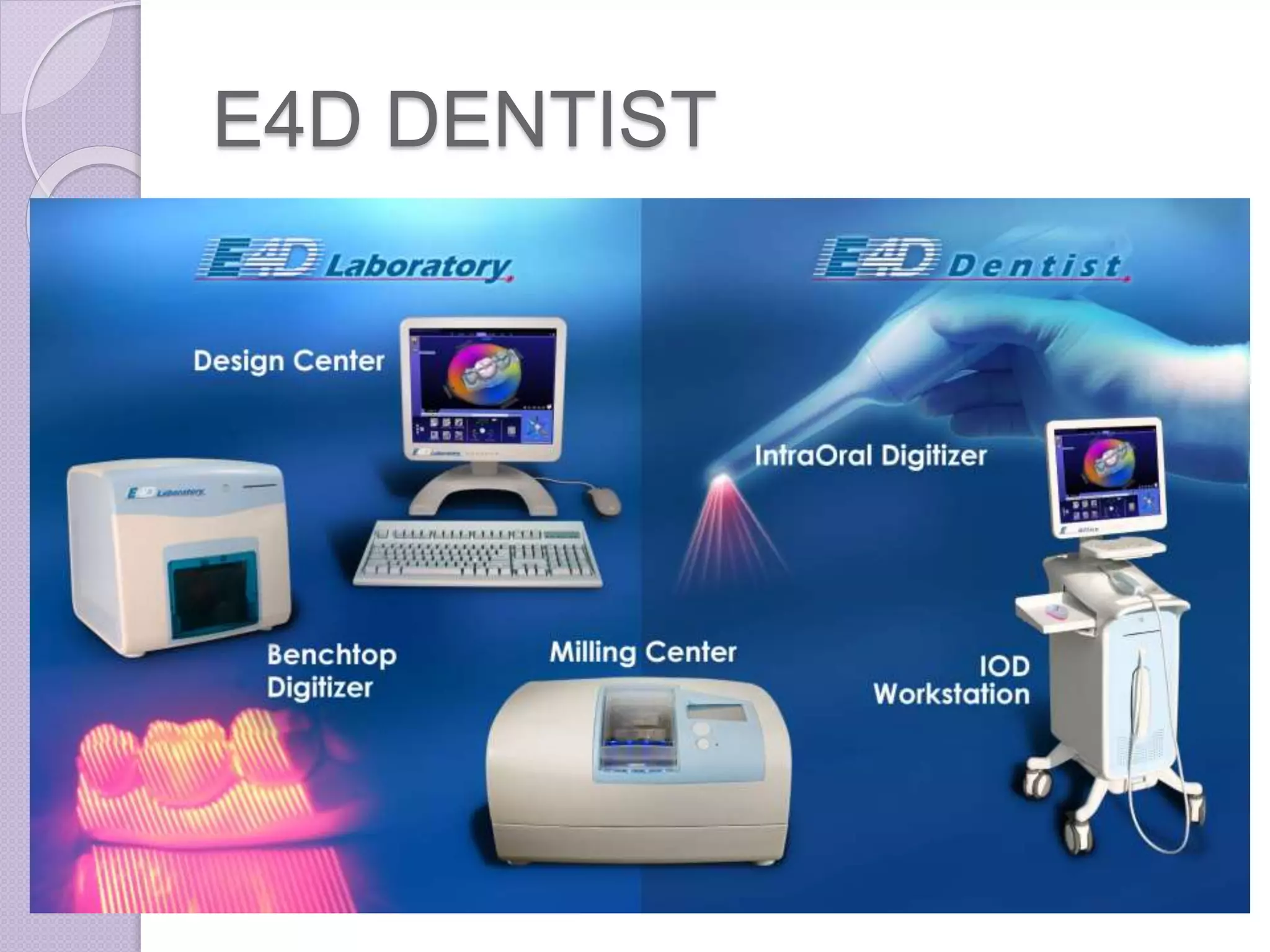
VIRTUAL IMPRESSIONS AND
VIRTUAL AND
STEREOLITHOGRAPHIC
MODELS
GUIDED BY- PRESENTED
BY-
DR. ASHISTARU SAHA(HOD) DR. POOJA
AGRAWAL
DR. ANUPAM PURWAR(READER)
DR. TUSHAR TANWANI (READER)
DR. PRANAY MAHASETH (READER)
CONTENT-
 Introduction
 Brief history of impressioning in
dentistry
 Advanced technologies
 Benefits of digital impression
 Disadvantages of digital impression
 Virtual models
 Rapid prototyping technologies
 Stereolithography
 Conclusion
 A JOURNEY TO THE SUCCESSFUL
PROSTHESIS STARTS WITH A PERFECT
IMPRESSION
IMPRESSION
IMPRESSION
 a negative likeness or copy in reverse
of the surface of an object;
 an imprint of the teeth and
adjacent structures for use in dentistry
Brief history of impressioning
in dentistry
 Impression compound around 1910
1925 Alphous pollerintroduced
AGAR
ALGINATE
POLYSULFIDE
 Introduced in late 1950s.
POLYETHER
 Introduced in1965
CONDENSATION SILICONE
ADDITION SILICONE
ELIMINATING STEPS AT THE
OFFICE
Tray Selection Dispensing Materials Setting of Materials
Disinfection Shipping
ELIMINATING STEPS AT THE
LAB
Pouring Plaster Base and Pin Die Cutting
Trimming Articulation
ADVANCED
TECHNOLOGIES
 Using Three-dimensional (3D)
digitizing scanners
CAD/CAM SYSTEMS
 originated in the 1950s
 The introduction of CAD/CAM
concepts into dental applications was
the brainchild of Dr. Francois Duret
DR. FRANCOIS DURET
BASED ON THE LOCATION OF
PROCESSING UNIT
 Chairside Production
 Laboratory Production
 Centralised fabrication in production
centre
Chairside digital impression
systems with laboratory transfer
capability
 i-Tero Lava C.O.S CEREC AC
CEREC
CEREC
 acronym for Chairside Economical
Restoration of Esthetic Ceramics
 3D digital scanner with a milling unit to
create dental restorations from
commercially available blocks of
ceramic material in a single
appointment.
 With this system, the impressioning
process necessitates achieving
adequate visualization of the margins of
the tooth preparation by proper tissue
retraction or troughing and hemostasis.
 The entire area being impressed needs
to be coated completely with a layer of
biocompatible titanium dioxide powder to
enable the camera to register all of the
tissues.
E4D DENTIST
E4D DENTIST
 an acronym for Dream, Design,
Develop, Deliver
 It consists of a cart containing the
design center (computer and monitor)
,laser scanner, a separate milling unit,
a job server and router for
communication.
DEDICATED IMPRESSION
SCANNING SYSTEMS
 iTero
 Lava C.O.S.
iTERO
iTERO
 digital impression system -introduced
in early 2007.
 The iTero system includes a computer,
monitor, mouse, integrated keyboard,
foot pedal, and scanning wand
organized on a well-designed mobile
cart.
 After all scans (at least 21) are
completed, the dentist steps on the
foot pedal and, within a few minutes,
the digital model is displayed on the
monitor.
 Digital data are sent wirelessly to
Cadent, where the digital impression
is refined and a hard plastic model is
milled.
 Cadent then returns the model to the
local dental laboratory, which
completes the final restoration.
LAVA C.O.S.
LAVA C.O.S.
 The Lava Chairside Oral Scanner
(C.O.S.) was born out of the research
of Professor Doug Hart and Dr. János
Rohály at the Massachusetts Institute
of Technology.
 The Lava C.O.S. unit consists of a
mobile cart, containing a computer, a
touch screen monitor, and a scanning
wand.
 Lava C.O.S. requires only enough
powdering to allow the scanner to
locate reference points. Therefore a
very light dusting of powder is
required, and is produced using the
powdering gun provided with the unit.
 After all the scans have been
reviewed for accuracy, the dentist
uses the touch screen monitor to
complete an on-screen laboratory
prescription.
 The data is sent wirelessly to the
laboratory technician, who then uses
customized software to cut the die and
mark the margin digitally.
 At the model manufacturing facility, a
stereolithography model is generated,
and is sent to the laboratory, where
the technician creates the final
restoration.
CEREC E4D iTero LAVA COS
Full-arch Yes No Yes Yes
Powder Yes Yes No Yes
In-Office Milling Yes Yes No No
Connectivity to Labs Yes No Yes Yes
In-Office Designing Yes Yes No No
Bridge 3 unit No Full Yes
Focal Distance Any 15 mm
iTero Vs. CEREC, E4D, & Lava COS
RECENT ADVANCES
BENEFITS OF DIGITAL
IMPRESSIONS
 Digital impressions eliminate the
uncomfortable experience of making a
physical impression.
 Digital impressions are an incredible
teaching tool because you can
evaluate your preparation on a 19-inch
monitor.
 The image on the monitor shows you if
you have captured all the needed data
before sending it to the lab.
 The accuracy of the mounting, bite
registration, and stability of the dies
create a model that allows the laboratory
technician to fabricate a final restoration
that has excellent marginal fit and
incredibly accurate occlusion.
DISADVANTAGES OF DIGITAL
IMPRESSIONS
 At this time, there is limited ability to
use this system for implant
impressions.
 Head size & weight of camera or
intraoral scanner.
 Cost
VIRTUAL MODELS
RAPID PROTOTYPING
 The term rapid prototyping (RP)
refers to a class of technologies that
can automatically construct physical
models from Computer-Aided Design
(CAD) data.
 These "three dimensional printers"
allow designers to quickly create
tangible prototypes of their designs,
rather than just two-dimensional
pictures.
 The key idea of this new RP
technology is based on the
decomposition of three-dimensional
computer models in the layers section
transverse thin, followed physically
forming layers and piling layer by
layer.
All RP techniques employ the same basic five-
step process.
1. Scan and create a CAD model of the design
2. Convert the CAD model to STL format
3. Slice the STL file into thin cross-sectional
layers
4. Construct the model one layer over the
other
5. Clean and finish the model
 STL file – Standard Triangulation
Language file
STL is a file format native to the
stereolithography CAD software created
by 3D Systems.
it is widely used for rapid prototyping and
computer-aided manufacturing
Layer by layer addition
DICOM FILES
 Digital Imaging and
Communications in
Medicine (DICOM) is a standard for
handling, storing, printing,
and transmitting information in medical
imaging. It includes a file
format definition and a
network communications protocol.
 DICOM files can be exchanged
between two entities that are capable
of receiving image and patient data in
DICOM format.
 Applications-
 radiography,
 ultrasonography,
 computed tomography (CT),
 magnetic resonance imaging (MRI)
CT scan MRI scan
INVESALIUS
 InVesalius is a free medical software used to
generate virtual reconstructions of structures
in the human body. Based on two-
dimensional images, acquired using
computed tomography or magnetic
resonance imaging equipment,
 the software generates virtual three-
dimensional models correspondent to
anatomical parts of the human body. After
constructing three-
dimensional DICOM images, the software
allows the generation
of STL (stereolithography) files. These files
can be used for rapid prototyping.
 The software’s name is a tribute to
Belgian physician Andreas
Vesalius (1514–1564), considered the
"father of modern anatomy"
Rapid Prototyping Technologies
 Stereolithography (SL)
 Laminated Object Manufacturing (LOM)
 Selective Laser Sintering (SLS)
 Fused Deposition Modeling (FDM)
 Inkjet (thermal phase change)
STEREOLITHOGRAPHY
STEREOLITHOGRAPHY (SL)
 This system consists of a bath of
photosensitive liquid resin, a model-
building platform, and an ultraviolet
(UV)
laser for curing the resin.
 The first process of this type of RP
was patented by Charles Hull (1984).
 The layers are cured sequentially and
bond together to form a solid object
beginning from the bottom of the model
and building up.
 As the resin is exposed to the UV light, a
thin well-defined layer thickness
becomes hardened.
 After a layer of resin is cured, the resin
platform is lowered within the bath by a
small known distance (typically 0.003-
0.002 in).
 A new layer of resin is wiped across
the surface of the previous layer using
a wiper blade, and this second layer is
subsequently exposed and cured.
 The process of curing and lowering
theplatform into the resin bath is
repeated until the full model is
complete.
• The self-adhesive property of the
material causes the layers to bond to
each other and eventually form a
complete, en bloc 3D object.
• The model is then removed from the
bath and cured for a further period of
time in a Uv cabinet.
MATERIALS USED
 1. Accura Bluestone-nano-
composite material
 2.SOMOS® NeXt-resin
 3. SOMOS® 18420 -epoxy resin,
medical & dental use.
 4. SOMOS® 9120-epoxy resin
 5. WaterShed® XC 11122-
liquid photopolymer
APPLICATION
 fabrication of surgical drilling
templates during dental implant
insertion.
LAMINATED OBJECT
MANUFACTURING
SELECTIVE LASER
SINTERING
FUSED DEPOSITION
MODELING
INKJET (THERMAL PHASE
CHANGE)
STEREOLITHOGRAPHY
MODELS
Three-dimensional (3D) Computerized axial tomography
(CAT) of a pediatric patient (A), stereolithography models of
the
same patient made with C. Acrylic (B, C).
USE OF STEREOLITHOGRAPHY IN
RESTORING A CASE OF MAXILLOFACIAL
DEFECT
3dMDfaceTM System.
Patient seated at 3dMDfaceTM.
Picture of patient taken with 3dMDfaceTM.
Altered photo frontal position.
Color model made with the ZPrinter R 450 and
high performance composite material.
Clear model made with the SLA 7000 and UV light-
activated epoxy resin.
Clay sculpture on model
Patient and final prosthesis without glasses
Patient and final prosthesis with glasses
MIRROR-IMAGE WAX
PATTERN OF AN EAR
Cast of
remaining ear
3-D images of
remaining ear and
mirror image. Image at
top right represents
mirror image of
remaining ear.
Thermoplastic (wax)
pattern of missing ear
produced from cast of
remaining ear.
Image of wax pattern and cast of remaining ear
projected in front of mirror to explain concept of technique.
CONCLUSION
 These optical impressions are
superior in technology and known for
its accuracy, saves the patients and
dentists time with a few laboratory
procedures and patients comfort
 but it has limitations like high cost, and
specialised equipment requirement
 As part of their upgrade process,
general
dentists must possess a basic
knowledge about the applications and
advantages of new 3D modeling
technologies used in dentistry, such as
those of stereolithography, an
exceptional support
tool for designing surgical treatment
and implant placement.
REFRENCES-
 Shruti S. Bammani a, 1, Pranav R. Birajdarb, 1 and Shriniwas
S Metanc, Dental Crown Manufacturing using
Stereolithography Method, Proc. of Int. Conf. on Advances in
Industrial and Production Engineering 2012
 Ma. del Socorro Islas Ruiz¹; Miguel Ángel Noyola Frías DDS²;
Ricardo Martínez Rider DDS²;Amaury Pozos Guillén DDS,
PhD 3; Arturo Garrocho Rangel DDS, PhD, Fundamentals of
Stereolithography, an Useful Tool for Diagnosis in Dentistry,
 V. N. V. Madhav1 , Rajendra Daule, Rapid Prototyping and its
Application in Dentistry, Journal of Dental & Allied Sciences
2013;2(2)57-61
 Gary M. Radz, DDS, Clinical impressions of digital
impressions,
www.dentaleconomics.com
 Nathan S. Birnbaum, DDS; and Heidi B. Aaronson, DMD,
Dental Impressions Using 3D Digital Scanners: Virtual
Becomes Reality
 Majd Al Mardini, DDS,a Carlo Ercoli, DDS,b and Gerald N.
Graser, DDS, MSc University of Rochester Eastman Dental
Center, Rochester, NY, A technique to produce a mirror-image
wax pattern of an ear using rapid prototyping technology
 Jennifer V. Sabol, DDS, MS,1 Gerald T. Grant, DMD, MS,2
Peter Liacouras, PhD, MS,3 & Stephen Rouse, DDS3, Digital
Image Capture and Rapid Prototyping of the Maxillofacial
Defect
 Internet
THANK YOU

2.VIRTUAL IMPRESSIONS AND VIRTUAL AND STEREOLITHOGRAPHIC MODELS.pptx

  • 1.
    VIRTUAL IMPRESSIONS AND VIRTUALAND STEREOLITHOGRAPHIC MODELS GUIDED BY- PRESENTED BY- DR. ASHISTARU SAHA(HOD) DR. POOJA AGRAWAL DR. ANUPAM PURWAR(READER) DR. TUSHAR TANWANI (READER) DR. PRANAY MAHASETH (READER)
  • 2.
    CONTENT-  Introduction  Briefhistory of impressioning in dentistry  Advanced technologies  Benefits of digital impression  Disadvantages of digital impression  Virtual models  Rapid prototyping technologies  Stereolithography  Conclusion
  • 3.
     A JOURNEYTO THE SUCCESSFUL PROSTHESIS STARTS WITH A PERFECT IMPRESSION
  • 4.
  • 5.
    IMPRESSION  a negativelikeness or copy in reverse of the surface of an object;  an imprint of the teeth and adjacent structures for use in dentistry
  • 6.
    Brief history ofimpressioning in dentistry  Impression compound around 1910
  • 7.
  • 8.
  • 9.
  • 10.
  • 11.
  • 12.
  • 13.
    ELIMINATING STEPS ATTHE OFFICE Tray Selection Dispensing Materials Setting of Materials Disinfection Shipping
  • 14.
    ELIMINATING STEPS ATTHE LAB Pouring Plaster Base and Pin Die Cutting Trimming Articulation
  • 15.
  • 16.
    CAD/CAM SYSTEMS  originatedin the 1950s  The introduction of CAD/CAM concepts into dental applications was the brainchild of Dr. Francois Duret
  • 17.
  • 18.
    BASED ON THELOCATION OF PROCESSING UNIT  Chairside Production  Laboratory Production  Centralised fabrication in production centre
  • 19.
    Chairside digital impression systemswith laboratory transfer capability  i-Tero Lava C.O.S CEREC AC
  • 20.
  • 23.
    CEREC  acronym forChairside Economical Restoration of Esthetic Ceramics  3D digital scanner with a milling unit to create dental restorations from commercially available blocks of ceramic material in a single appointment.
  • 24.
     With thissystem, the impressioning process necessitates achieving adequate visualization of the margins of the tooth preparation by proper tissue retraction or troughing and hemostasis.  The entire area being impressed needs to be coated completely with a layer of biocompatible titanium dioxide powder to enable the camera to register all of the tissues.
  • 25.
  • 26.
    E4D DENTIST  anacronym for Dream, Design, Develop, Deliver  It consists of a cart containing the design center (computer and monitor) ,laser scanner, a separate milling unit, a job server and router for communication.
  • 27.
  • 28.
  • 31.
    iTERO  digital impressionsystem -introduced in early 2007.  The iTero system includes a computer, monitor, mouse, integrated keyboard, foot pedal, and scanning wand organized on a well-designed mobile cart.
  • 32.
     After allscans (at least 21) are completed, the dentist steps on the foot pedal and, within a few minutes, the digital model is displayed on the monitor.  Digital data are sent wirelessly to Cadent, where the digital impression is refined and a hard plastic model is milled.
  • 33.
     Cadent thenreturns the model to the local dental laboratory, which completes the final restoration.
  • 34.
  • 35.
    LAVA C.O.S.  TheLava Chairside Oral Scanner (C.O.S.) was born out of the research of Professor Doug Hart and Dr. János Rohály at the Massachusetts Institute of Technology.  The Lava C.O.S. unit consists of a mobile cart, containing a computer, a touch screen monitor, and a scanning wand.
  • 36.
     Lava C.O.S.requires only enough powdering to allow the scanner to locate reference points. Therefore a very light dusting of powder is required, and is produced using the powdering gun provided with the unit.
  • 37.
     After allthe scans have been reviewed for accuracy, the dentist uses the touch screen monitor to complete an on-screen laboratory prescription.  The data is sent wirelessly to the laboratory technician, who then uses customized software to cut the die and mark the margin digitally.
  • 38.
     At themodel manufacturing facility, a stereolithography model is generated, and is sent to the laboratory, where the technician creates the final restoration.
  • 40.
    CEREC E4D iTeroLAVA COS Full-arch Yes No Yes Yes Powder Yes Yes No Yes In-Office Milling Yes Yes No No Connectivity to Labs Yes No Yes Yes In-Office Designing Yes Yes No No Bridge 3 unit No Full Yes Focal Distance Any 15 mm iTero Vs. CEREC, E4D, & Lava COS
  • 41.
  • 42.
    BENEFITS OF DIGITAL IMPRESSIONS Digital impressions eliminate the uncomfortable experience of making a physical impression.  Digital impressions are an incredible teaching tool because you can evaluate your preparation on a 19-inch monitor.
  • 43.
     The imageon the monitor shows you if you have captured all the needed data before sending it to the lab.  The accuracy of the mounting, bite registration, and stability of the dies create a model that allows the laboratory technician to fabricate a final restoration that has excellent marginal fit and incredibly accurate occlusion.
  • 44.
    DISADVANTAGES OF DIGITAL IMPRESSIONS At this time, there is limited ability to use this system for implant impressions.  Head size & weight of camera or intraoral scanner.  Cost
  • 45.
  • 46.
    RAPID PROTOTYPING  Theterm rapid prototyping (RP) refers to a class of technologies that can automatically construct physical models from Computer-Aided Design (CAD) data.  These "three dimensional printers" allow designers to quickly create tangible prototypes of their designs, rather than just two-dimensional pictures.
  • 47.
     The keyidea of this new RP technology is based on the decomposition of three-dimensional computer models in the layers section transverse thin, followed physically forming layers and piling layer by layer.
  • 48.
    All RP techniquesemploy the same basic five- step process. 1. Scan and create a CAD model of the design 2. Convert the CAD model to STL format 3. Slice the STL file into thin cross-sectional layers 4. Construct the model one layer over the other 5. Clean and finish the model
  • 49.
     STL file– Standard Triangulation Language file STL is a file format native to the stereolithography CAD software created by 3D Systems. it is widely used for rapid prototyping and computer-aided manufacturing
  • 50.
  • 51.
    DICOM FILES  DigitalImaging and Communications in Medicine (DICOM) is a standard for handling, storing, printing, and transmitting information in medical imaging. It includes a file format definition and a network communications protocol.
  • 52.
     DICOM filescan be exchanged between two entities that are capable of receiving image and patient data in DICOM format.  Applications-  radiography,  ultrasonography,  computed tomography (CT),  magnetic resonance imaging (MRI)
  • 53.
  • 54.
    INVESALIUS  InVesalius isa free medical software used to generate virtual reconstructions of structures in the human body. Based on two- dimensional images, acquired using computed tomography or magnetic resonance imaging equipment,  the software generates virtual three- dimensional models correspondent to anatomical parts of the human body. After constructing three- dimensional DICOM images, the software allows the generation of STL (stereolithography) files. These files can be used for rapid prototyping.
  • 55.
     The software’sname is a tribute to Belgian physician Andreas Vesalius (1514–1564), considered the "father of modern anatomy"
  • 56.
    Rapid Prototyping Technologies Stereolithography (SL)  Laminated Object Manufacturing (LOM)  Selective Laser Sintering (SLS)  Fused Deposition Modeling (FDM)  Inkjet (thermal phase change)
  • 57.
  • 58.
    STEREOLITHOGRAPHY (SL)  Thissystem consists of a bath of photosensitive liquid resin, a model- building platform, and an ultraviolet (UV) laser for curing the resin.  The first process of this type of RP was patented by Charles Hull (1984).
  • 59.
     The layersare cured sequentially and bond together to form a solid object beginning from the bottom of the model and building up.  As the resin is exposed to the UV light, a thin well-defined layer thickness becomes hardened.  After a layer of resin is cured, the resin platform is lowered within the bath by a small known distance (typically 0.003- 0.002 in).
  • 60.
     A newlayer of resin is wiped across the surface of the previous layer using a wiper blade, and this second layer is subsequently exposed and cured.  The process of curing and lowering theplatform into the resin bath is repeated until the full model is complete.
  • 61.
    • The self-adhesiveproperty of the material causes the layers to bond to each other and eventually form a complete, en bloc 3D object. • The model is then removed from the bath and cured for a further period of time in a Uv cabinet.
  • 62.
    MATERIALS USED  1.Accura Bluestone-nano- composite material  2.SOMOS® NeXt-resin  3. SOMOS® 18420 -epoxy resin, medical & dental use.  4. SOMOS® 9120-epoxy resin  5. WaterShed® XC 11122- liquid photopolymer
  • 63.
    APPLICATION  fabrication ofsurgical drilling templates during dental implant insertion.
  • 64.
  • 65.
  • 66.
  • 67.
  • 68.
    STEREOLITHOGRAPHY MODELS Three-dimensional (3D) Computerizedaxial tomography (CAT) of a pediatric patient (A), stereolithography models of the same patient made with C. Acrylic (B, C).
  • 69.
    USE OF STEREOLITHOGRAPHYIN RESTORING A CASE OF MAXILLOFACIAL DEFECT 3dMDfaceTM System.
  • 70.
    Patient seated at3dMDfaceTM.
  • 71.
    Picture of patienttaken with 3dMDfaceTM.
  • 72.
  • 73.
    Color model madewith the ZPrinter R 450 and high performance composite material.
  • 74.
    Clear model madewith the SLA 7000 and UV light- activated epoxy resin.
  • 75.
  • 76.
    Patient and finalprosthesis without glasses
  • 77.
    Patient and finalprosthesis with glasses
  • 78.
    MIRROR-IMAGE WAX PATTERN OFAN EAR Cast of remaining ear
  • 79.
    3-D images of remainingear and mirror image. Image at top right represents mirror image of remaining ear.
  • 80.
    Thermoplastic (wax) pattern ofmissing ear produced from cast of remaining ear.
  • 81.
    Image of waxpattern and cast of remaining ear projected in front of mirror to explain concept of technique.
  • 82.
    CONCLUSION  These opticalimpressions are superior in technology and known for its accuracy, saves the patients and dentists time with a few laboratory procedures and patients comfort  but it has limitations like high cost, and specialised equipment requirement
  • 83.
     As partof their upgrade process, general dentists must possess a basic knowledge about the applications and advantages of new 3D modeling technologies used in dentistry, such as those of stereolithography, an exceptional support tool for designing surgical treatment and implant placement.
  • 84.
    REFRENCES-  Shruti S.Bammani a, 1, Pranav R. Birajdarb, 1 and Shriniwas S Metanc, Dental Crown Manufacturing using Stereolithography Method, Proc. of Int. Conf. on Advances in Industrial and Production Engineering 2012  Ma. del Socorro Islas Ruiz¹; Miguel Ángel Noyola Frías DDS²; Ricardo Martínez Rider DDS²;Amaury Pozos Guillén DDS, PhD 3; Arturo Garrocho Rangel DDS, PhD, Fundamentals of Stereolithography, an Useful Tool for Diagnosis in Dentistry,  V. N. V. Madhav1 , Rajendra Daule, Rapid Prototyping and its Application in Dentistry, Journal of Dental & Allied Sciences 2013;2(2)57-61  Gary M. Radz, DDS, Clinical impressions of digital impressions, www.dentaleconomics.com
  • 85.
     Nathan S.Birnbaum, DDS; and Heidi B. Aaronson, DMD, Dental Impressions Using 3D Digital Scanners: Virtual Becomes Reality  Majd Al Mardini, DDS,a Carlo Ercoli, DDS,b and Gerald N. Graser, DDS, MSc University of Rochester Eastman Dental Center, Rochester, NY, A technique to produce a mirror-image wax pattern of an ear using rapid prototyping technology  Jennifer V. Sabol, DDS, MS,1 Gerald T. Grant, DMD, MS,2 Peter Liacouras, PhD, MS,3 & Stephen Rouse, DDS3, Digital Image Capture and Rapid Prototyping of the Maxillofacial Defect  Internet
  • 86.