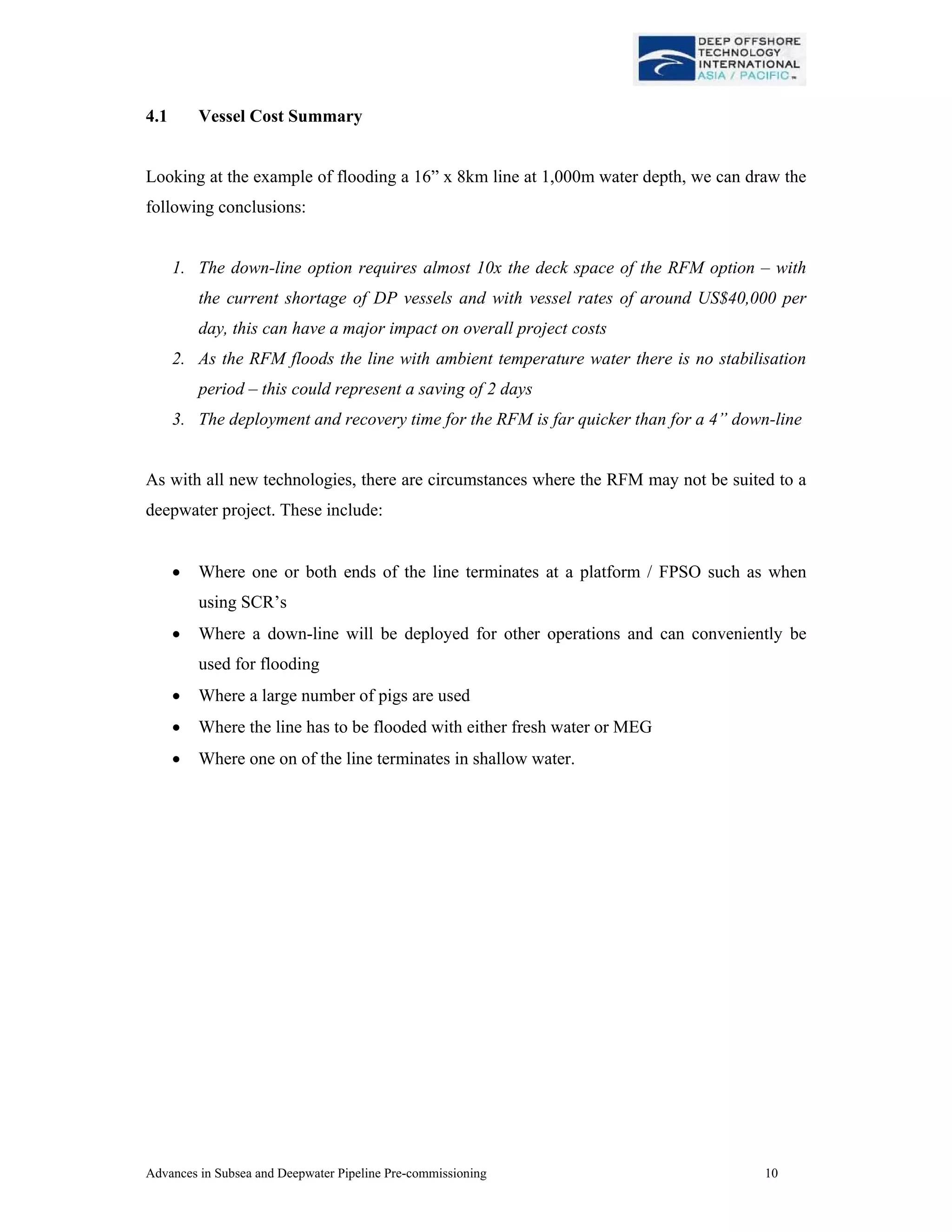
This document discusses advances in pre-commissioning of subsea and deepwater pipelines. It describes challenges of testing pipelines without surface connections and reviews technologies like remote flooding modules and smart gauge tools to enable subsea testing. Using a case study of an 8km, 16" pipeline at 1,000m depth, it analyzes vessel requirements and costs of traditional vessel-based systems versus newer remote flooding modules. The remote flooding module reduces vessel time on site from 77 hours to 9 hours, space needs from 290m2 to 32m2, and eliminates the 48 hour water temperature stabilization period to lower overall project costs.
Subsea Field Development for an ideal Green field.Emeka Ngwobia
• The Daiyeriton Field is a green field development project. The subsea field layout with its drill centers has been illustrated in slide 2. New flowlines and pipelines will tie-in to the existing Daiyeriton floating production, storage, and offloading (FPSO) vessel. The new system will enable the transportation of production and injection fluids to and from the Daiyeriton field facilities from five new drill centers: DC-SW, DC-NW, DC-SE, DC-NE and DC-E. DC-SE, DC-SW, DC-NE and DC-E are dedicated production drill centers while DC-NW is a dedicated WI drill center. Gas lift will be provided at the riser base of a new 12-inch production flowline.
•The water depth at the proposed development sites range from 800 m to 1000 m.
At 300 meters depth, we have it covered. But at depths up to 3000
meters, the physical conditions demand a radical re-think around
techniques and technology.
Course Description
This concise course is well balanced and based on more than 30 years of true project experience in Shallow and Deep Water fields around the world, from concept evaluation to first production. It is designed for Project Managers, Project Engineers, experienced or new to Subsea & highly suitable for Cost, Planning, Offshore Installation and Offshore Operation Engineers.
All the Lectures (up-dated on a regular basis) are presented with text, figures and DVDs with videos and detailed animations, used to illustrate many key points of Subsea Technologies. The objective of the course is to equip Engineers and Technicians with a good understanding on the Engineering of Subsea Production Systems (SPS) together with Umbilicals, Risers and Flowlines (SURF) required to link and operate it from
the Host.
Course Highlights
- Definition of Subsea Engineering for Field Developments / Floaters requirements Field Lay-out and System Design
- Flow Assurance Issues, Mitigation and Hydraulic Analysis
- Well Heads and Xmas Trees
- Templates, Manifolds and Subsea Hardware
- Subsea Wells Operations and Work Overs
- Inter Field Flowlines & Small Export Pipelines
- Production Riser Systems for Floaters
- Subsea Production Control Systems & Chemical Injection (including Umbilicals)
- Reliability Engineering and Risk Analysis
- Underwater Inspection, Maintenance & Repair
- New technologies for S.P.S
- 3 Major case studies for Oil, Gas and Heavy Oil Production including updates from Total, Shell and BP
This Presentation was originally given on February 2009, by JP Kenny. This company, today, is known as Wood Group Kenny. said presentation was given at the Underwater Intervention conference, and it excels in explaining what exactly is in the works, in terms of subsea technology, and where said technology is headed.
Design and Evaluation of Submersible 11/0.415kV Distribution Substation for F...TELKOMNIKA JOURNAL
Flood levels exceeding 2 metres above ground level has been observed causing electrical equipment in the 11/0.415kV substation to be fully submerged. This caused widespread supply disruption as the equipment need to be switched off due to safety reasons and prevention of further equipment damage. The use of submersible equipment and accessories has been identified as one of the mitigation methods to ensure continuous electrical supply during flood events. A research project was undertaken to develop the design criteria of the selection of submersible equipment and accessories as well as to develop the test method and evaluate the selected submersible equipment and accessories in a substation configuration. All the equipment could continuously operate in ON condition during the wet test. However, design improvements are suggested for the submersible switchgear and feeder pillar for better performance during and after flood events.
What is a Shoreline Management Plan?
Developed in partnership by local authorities, regulators and other stakeholders, a Shoreline Management Plan (SMP) is a high level non-statutory policy document designed to assist coastal flood and erosion risk management planning. It provides a large-scale assessment of the risks (to people, property, the natural and historic environment) associated with coastal erosion and flooding at the coast over the long-term. It also proposes policies to help manage these risks sustainably over the next hundred years.
The SMP enables planners and regulators to plan for and manage the way that the coast will change. This could be by maintaining or improving defences, by enabling the natural processes to play a greater role, creating new natural habitat or by helping areas that are at risk of flooding at some point in the future to cope with and limit the impact of flooding events.
The SMP2 for the Severn Estuary updates an earlier SMP1 (2000) for the estuary. It aims to provide more certainty for landowners, residents and businesses; to know how the coast will be managed by regulators during the next 100 years, so that they can plan ahead and make decisions about investments, homes, development and the management of their resources.
DAMMAM SECOND INDUSTRIAL CITY - IPS REHABILITATION WORKSIslam Nassef
Design capacities of the lift station
approximately 1670 m3/h. The
GWC’s initial goal for this project
is to develop a prioritized list of
repair/refurbishment projects based upon a comprehensive condition assessment and criticality analysis of IPS lift station planned to remain in operation.
Center for Sustainable Shale Development Comparison to State/Federal RegulationsMarcellus Drilling News
A chart comparing the 15 standards proposed by the CSSD to existing standards and regulations by PA, OH, WV and the federal government. The CSSD is attempting to show why their "voluntary" standards are better than existing standards. They make statements that CSSD certification/standard is meant to work with state regulations, not supersede or replace it. However, the CSSD standards are expensive to follow, especially with smaller drillers--and without proof that they protect the environment any more than existing regulations.
Optimizing completions in deviated and extended reach wells is a key to safe drilling and optimum
production, particularly in complex terrain and formations. This work summarizes the systematic methodology
and engineering process employed to identify and refine the highly effective completions solution used in ERW
completion system and install highly productive and robust hard wares in horizontal and Extended Reach Wells
for Oil and Gas. A case study of an offshore project was presented and discussed. The unique completion design,
pre-project evaluation and the integrated effort undertaken to firstly, minimize completion and formation damage.
Secondly, maximize gravel placement and sand control method .Thirdly, to maximize filter cake removal
efficiencies. The importance of completions technologies was identified and a robust tool was developed .More
importantly, the ways of deploying these tools to achieve optimal performance in ERW’s completions was done.
The application of the whole system will allow existing constraints to be challenged and overcome successfully;
these achievements was possible, by applying sound practical engineering principle and continuous optimization,
with respect to the rig and environmental limitation space and rig capacity.
Keywords: Well Completions , Deviated and Extended Rearch Wells , Optimization
Remotely Operated Vehicles (ROVs), A Subsea EnablerAhmed Abo Bakr
A brief of my Udemy Course: Remotely Operated Vehicles (ROVs), A Subsea Enabler
Discovering The Deepwater World Made Possible, With a Focus on the Petroleum Engineering (Oil and Gas Industry)
If you like the slides, you can find the full course on Udemy here: https://www.udemy.com/course/remotely-operated-vehicles-rovs-a-subsea-enabler/?referralCode=AE53ABB765F1B8FD2F27
Unlock the mysteries of Remotely Operated Vehicles (ROVs) with this comprehensive course based on my book "Remotely Operated Vehicles (ROVs): Current Systems, Future Trends, and Operational Challenges" available on Amazon.
Discount Offer:
*Reach out to me on LinkedIn for a Special Discounted Rate for University Students!*
This course coupled with the Summary Q & A and practice questions shall take you on a step-by-step journey to learn more and more about ROVs, covering the following main concepts:
Module 1: Understanding ROVs
-Historical Background and Maturity
-ROV Classifications
-Applications and Capabilities
-ROV Systems, Components, and Tooling
Module 2: ROV Trends
-Resident ROV (RROV) and Empowered ROV (EROV)
-Benefits, Working Principles, and System Challenges
-AUV System Components and Levels of Autonomy
-Virtual Reality (VR) and Augmented Reality (AR)
-Hybrid Solutions
Module 3: Challenges and Opportunities
-Reliability and Maintainability
-Addressing Poor Visibility and Weather Dependency
-Tackling Lost and Malfunctioned Vehicles
-Safeguarding Against Security Threats
Module 4: ROV Professionals Survey
-Methodology and Approach
-Survey Questions and Results Discussion
-Operational and Safety Challenges
-Incidents and Near Misses
What You Will Learn:
-An in-depth knowledge of ROV systems, subsystems, and components.
-Explore ROV tooling and understand its applications.
-Stay updated on the latest ROV trends and recent developments.
-Address challenges faced by Resident ROV (RROV) and Empowered ROV (EROV) systems.
-Understand AUV system components and their main operations.
-Identify and overcome challenges, opportunities, and threats in underwater vehicles.
-Gain insights from a survey of ROV professionals, including pilots, engineers, and industry representatives.
Why Enroll:
This course provides a step-by-step journey through the fascinating world of ROVs. Whether you are a student, engineer, or industry professional, this course equips you with the knowledge and skills needed to navigate the complexities of underwater vehicles.
Don't miss the chance to explore the depths of ROV technology! Enroll now and understand this field.
The new Center for Sustainable Shale Development, a collective of both drilling companies and environmentalist groups, have proposed a new standards certification program. These 15 standards are the initial "first cut" at promoting more environmentally-friendly shale in the Marcellus Shale region. The intent is for drillers and pipeline companies to become certified by the CSSD. Without certification? Persona non grata.
1. Advances in Subsea and Deepwater Pipeline Pre-commissioning 1
ADVANCES IN SUBSEA &
DEEPWATER PIPELINE PRE-
COMMISSIONING
JOHN GROVER
BJ PROCESS AND PIPELINE SERVICES
Background
The increasing number of subsea and deepwater developments brings new challenges where
there are no surface connections to the pipeline available for pipeline testing and pre-
commissioning.
Once constructed / installed such subsea and deepwater systems still have to undergo certain
pre-commissioning and commissioning operations, from initial flooding, gauging & testing
up to final start up.
Whilst the provision of such services in shallow water and topside-to-topside developments is
routinely achieved, providing the same services at water depths in excess of 1,000m poses
many challenges. In this paper we shall review the unique challenges in providing such
services deepwater, and then review current / planned technologies including:
Flooding and pigging subsea pipelines using a Remote Flooding Module (RFM) – by
using the available hydrostatic head to flood and pig subsea pipelines whilst meeting
the project requirements in terms of pig speed, filtration and chemical treatment.
Use of subsea ROV driven pumping units for completion of flooding and
pressurisation – by using the hydraulic power from a work class ROV to power a
custom built pump skid built connected on to the RFM allowing all pigging and
pipeline testing to be performed subsea
Use of smart gauge tools (SGT) to gauge pipelines without using aluminium gauge
plates – this allows the gauging of lines with reduced bore PLETs at each end. Also
the ability to communicate the result of the gauging run thru-wall without the need to
recover the gauge plate to surface. This allows testing without pig recovery.
Use of subsea data loggers to record pressures and temperatures during subsea testing,
and use of systems to transmit this data to surface real-time during the test period
2. Advances in Subsea and Deepwater Pipeline Pre-commissioning 2
1.0 Asia Pacific Deepwater Market Overview
Looking at the Asia Pacific Market, the following table shows some of the deepwater projects
currently in progress within the region.
Looking at Australia in more detail we have visibility on the following deepwater prospects:
Operator Field
Year
Discovered Status
WD
(M) Development Type
Chevron Gorgon Central 1983 Firm Plan 250 Subsea Satellite to Onshore Facility
Chevron Gorgon North 1981 Firm Plan 246 Subsea Satellite to Onshore Facility
Chevron Gorgon South 1980 Firm Plan 220 Subsea Satellite to Onshore Facility
Chevron
Jansz SE/Io
South 2000 Firm Plan 1300 Subsea Satellite to Onshore Facility
Chevron Wheatstone 2004 Firm Plan 216 Subsea Satellite to Fixed Production
Exxon Mobil Jansz 2002 Firm Plan 1300 Subsea Satellite to Onshore Facility
Inpex Ichthys 2000 Firm Plan 230 Floating Production
Shell Prelude/Tocatta 2007 Probable 200 Fixed & Floating Production and Subsea
Woodside Brecknock 1979 Possible 300 Floating Production
Woodside Calliance 2000 Possible 420 Subsea Satellite to Floating Production
Woodside Pluto 2005
Under
Development976 Fixed Production Platform and Subsea
Woodside Sunrise 1974 Possible 180 Fixed Production Platform and Subsea
Woodside Torosa 1971 Possible 250 Fixed & Floating Production and Subsea
Woodside Troubador 1974 Possible 160 Subsea Satellite to Fixed Production
Figure 1 – Asia Pacific Deepwater Developments
Figure 2 – Australia Deepwater Developments
3. Advances in Subsea and Deepwater Pipeline Pre-commissioning 3
The offshore / deepwater pipeline market dynamics are explained further below:
1.1 Market Overview Summary
From the data in section 1 we can draw the following conclusions:
a. That there are a large number of deepwater pipeline projects planned in the Asia
Pacific region between 2008 and 2014
b. There is steep in crease in global deepwater pipeline installation planned in the next
few years, peaking in 2011
c. Services and techniques will be required to assist with the pre-commissioning and
commissioning of such pipeline systems
Figure 3 – Global Offshore Pipe lay Forecast
Figure 4 – Global Pipe lay Forecast by diameter
4. Advances in Subsea and Deepwater Pipeline Pre-commissioning 4
2.0 Pipeline Pre-commissioning – What Do We Mean?
The following flow chart illustrates the pre-commissioning process as typically applied to oil
pipelines. The process for gas lines is similar but involved additional steps prior to handover
such as removal of hydrotest water (dewatering), drying, MEG swabbing and nitrogen
packing (these are not covered in this paper).
Cleaning & gauging of
pipeline section
Flooding & testing of
pipeline section
Depressurise line and
handover to client filled
with treated water
Displace hydrotest
water with oil
Dewater using
compressed air
BJ Activity
Client
Commission the pipeline
Perform Caliper Survey,
possibly c/w dewatering
Nitrogen purge and pack
the line
Treat the line with batch
of corrosion inhibitor
Optional Services
Figure 5 – on LHS shows a
typical offshore vessel based
spread required to deliver
the above services to a
subsea pipeline.
5. Advances in Subsea and Deepwater Pipeline Pre-commissioning 5
3.0 The Aims of Subsea Pipeline Flooding
The first subsea pigging units were conceived and developed to overcome the problems
associated with flooding and pigging pipelines in deep water.
The latest subsea flooding device is the BJ RFM (Remote Flooding Module), which
essentially achieves the same objectives using up to date ROV and Subsea technologies.
The RFM is a Subsea flow control and regulation system. Once positioned on the seabed and
connected to the pipeline to be flooded or pigged by HP loading arm, it is “operated” by the
ROV opening the valves to the pipeline.
The hydrostatic head of the sea then enters the pipeline through the RFM because of the
differential pressure between the inside of the pipeline, which is at atmospheric pressure and
the sea.
Seawater enters the RFM via a filter manifold, which is installed at the specified filtration
level, usually between 50 and 200 microns. It passes through a Venturi device, which creates
a small pressure drop in the on board flexible RFM chemical tanks which are connected to
the water flow pipework. This small differential pressure is used to induce anti-corrosion
chemicals into the water flow at the desired rate. This is pre-set prior to deployment and ROV
adjusted Subsea if necessary via control valves.
Figure 6 – Overview of Remote Flooding Module
6. Advances in Subsea and Deepwater Pipeline Pre-commissioning 6
The chemically treated water flow is controlled to a pre-determined rate via a flow regulation
system. This maintains the water flow at the desired speed to match specified or optimum pig
speed or flooding rates. Again this can be pre-set prior to deployment and because the rate is
controlled at a steady level the chemical inducement is assured throughout the entire
“unassisted” operation. A Boost pump is required to complete final pigging operations due to
pressure equalisation. This pump is ROV driven, usually operated when the ROV returns to
location to disconnect and recover the RFM, and in Deepwater is required only for a very
short time.
The vessel and ROV can leave the unit in isolation on the seabed during the unassisted
operations and carry out other tasks. There is no need for connection to anything other than
the pipeline. On board batteries power data-logging instrumentation which logs flows,
chemical rates etc, and visual readouts allows the ROV to check status before it leaves and
when it returns.
The RFM is positioned on the seabed by ROV and connected to the pipeline to be flooded via
the innovative rigid loading arm pipe system. The ROV then positions itself on the unit’s roof
from where it can view instruments and operate valves to monitor the initial stages of the
operation and adjust if necessary chemical control valves.
Filtration and chemical treatment specifications are fully met by onboard facilities. Chemicals
are stored onboard in flexible tanks and introduced by a Venturi system regulated by
detecting changes in the water flow through the unit and automatically adjusting the chemical
flow accordingly.
To summarise the aims of subsea pipeline flooding:
• Reduce the size of vessel required for pre-commissioning operations
• Negate the need for the vessel to remain on station during the bulk of the operations
• Remove the need for an expensive down-line, which is prone to damage
• Reduce schedule by increasing possible pig speed
• Reduce schedule by use of seabed water removing thermal stabilisation for Hydrotest
• Reduce crew size, equipment spread size, environmental impact by removal of diesel
engines on pumps, improve safety by taking operations off-deck
7. Advances in Subsea and Deepwater Pipeline Pre-commissioning 7
4.0 Offshore Vessel Requirements – the Cost Driver
Previously in this paper I have described the functionality and development of subsea
flooding and testing, and in the following section we look at the commercial drivers to use
such a system. As an example we take the following pipeline as an example:
Line NPS 16”
Wall Thickness 12.5mm
Line Length 8KM
Water Depth at launcher 1000m
Water Depth at receiver 1000m
Water Temp at surface 28°C
Water Temp at Seabed 4°C
Average Flooding pig velocity required 0.5 m/sec
Flooding Rate Required 3,420 lpm
Table 1 – Pipeline details (illustration)
The important data from the above is that we need to inject 3,420 lpm of filtered, treated sea
water into a pipeline at a water depth of 1000m. There are 2 ways to achieve this:
Use a Vessel Based Spread and Down-line
The vessel based spread must be designed to deliver 3,420 lpm in to the pipeline – hence the
first consideration is the size of the down-line required. Having looked at the various pressure
drops across the down-line, we then need to evaluate the pump power (HHP / BHP) required
to overcome the system pressure losses and deliver the flow to the system.
Down-line
Diameter
Down-line
Length
Pressure Drop
in barg *
HHP required
for 1m/sec
BHP required
for 1m/sec**
2” 1,200m 210 barg 1,600 HHP 2,560 BHP***
3” 1,200m 78 barg 594 HHP 1,014 BHP
4” 1,200m 24 barg 183 HHP 382 BHP****
Table 2 – Pressure drops and HHP calculations vs. down-line diameter
* Using Mears pipe flow calculator
** Based on 65% efficiency (centrifugal pump) plus 100bhp for engine ancillaries
*** Maximum power from portable, marinised diesel engines approx. 1,800 BHP
**** Pump packages rated at 350 to 500 BHP readily available
8. Advances in Subsea and Deepwater Pipeline Pre-commissioning 8
Thus taking the data in table 2 we can see that to flood this notional 16” pipeline at a depth of
1,000m would require:
• A 4” x 1,200m down-line including reel and installation system
• A 4” hot stab to connect the hose to the subsea launcher
• 2 qty diesel driven 500 bhp centrifugal pumps
• Lift pumps, break tanks, filters, chemical injection units and hoses
To put this into perspective in figure 7 we show the deck space required on a DP vessel for
the above spread (figure 8 illustrates space requirement for similar RFM spread):
Figure 7 – Vessel Space Requirement Figure 8 – Reduced Space Using RFM
The vessel based spread c/w down-line requires a deck space of approx. 290m2
to flood a 16”
pipeline at 0.5m/sec. To perform such an operations the following steps are required:
a. Deploy down-line and stab in to subsea launcher - 12 hours
b. Flood the 8km line at 0.5m/sec - 5 hours
c. Recover down-line to surface - 12 hours
d. Allow fill water temperature to stabilise - 48 hours
e. TOTAL TIME FOR FLOODING - 77 HOURS
9. Advances in Subsea and Deepwater Pipeline Pre-commissioning 9
Use a Vessel Based RFM to Flood the Line
Figure 7 shows the deck space required for the
RFM – this is approx. 32m2
. The RFM can carry
sufficient chemicals to fill 16” x 8km in a single
deployment. Using the vessel crane the RFM
can be quickly deployed subsea and connected
to the subsea launcher. Thereafter it can perform
the initial flooding of the pipeline at velocities
up to 1m/sec.
16" Pipeline
Predicted End Point of Flooding by RFM:
Data
Starting end depth d1 = 1000 metres.
Finishing end depth d2 = 1000 metres.
Total line length L = 8 kilometres.
Internal diameter of line b = 371.4 millimetres.
Assumed or required pig speed v = 0.5 m/second.
Assumed pig (train) driving pressure 2 bar.
(If unknown, assume 1 bar per pig.)
Slug length trapped air before boost 81 metres.
Proportion of line flooded by unassisted RFM = 99.0 %.
Time taken for filling by RFM at pig speed 0.5m/s is 4.4 hours.
Volume to be boost pumped for completion = 8.8 cubic metres.
RFM
Sta
Pipelin
d d
Wat Ai
En
Figure 10 – RFM calculation for 16” x 8km line.
In figure 8 we can see that the RFM can flood the line within 4.4 hours and that 8.8m3
has to
be pumped by the ROV powered boost pump – please consider the line has been flooded with
water at seabed ambient temperature.
The vessel based RFM spread requires a deck space of approx. 32m2
to flood a 16” pipeline
at 0.5m/sec. To perform such an operations the following steps are required:
a. Deploy down-line and stab in to subsea launcher - 2 hours
b. Flood the 8km line at 0.5m/sec - 5 hours
c. Recover down-line to surface - 2 hours
d. Allow fill water temperature to stabilise - 0 hours
e. TOTAL TIME FOR FLOODING - 9 HOURS
Figure 9 – RFM ready to deploy
10. Advances in Subsea and Deepwater Pipeline Pre-commissioning 10
4.1 Vessel Cost Summary
Looking at the example of flooding a 16” x 8km line at 1,000m water depth, we can draw the
following conclusions:
1. The down-line option requires almost 10x the deck space of the RFM option – with
the current shortage of DP vessels and with vessel rates of around US$40,000 per
day, this can have a major impact on overall project costs
2. As the RFM floods the line with ambient temperature water there is no stabilisation
period – this could represent a saving of 2 days
3. The deployment and recovery time for the RFM is far quicker than for a 4” down-line
As with all new technologies, there are circumstances where the RFM may not be suited to a
deepwater project. These include:
• Where one or both ends of the line terminates at a platform / FPSO such as when
using SCR’s
• Where a down-line will be deployed for other operations and can conveniently be
used for flooding
• Where a large number of pigs are used
• Where the line has to be flooded with either fresh water or MEG
• Where one on of the line terminates in shallow water.
11. Advances in Subsea and Deepwater Pipeline Pre-commissioning 11
5.0 Advances Made in Subsea Pigging Equipment
The original Subsea Pigging Unit was designed by pre-commissioning Engineers with little
input from ROV and Subsea specialists, despite efforts to include them.
Whilst the device was successful in achieving its’ pre-commissioning objectives, it wasn’t the
most optimum method of operation for the ROV or deployment Vessel. Unwieldy HP
flexible Jumper hoses, relatively crude instrumentation and brand new ways to use Choke
Assemblies meant there were areas to improve, for example:
.
• The RFM holds more chemical than the original Subsea unit, allowing less recovery
and deployment cycles and use on longer and larger lines
• The RFM uses rigid loading arm technology to reduce Subsea connection times and
reduce the risk of damage to HP flexible jumper hoses
• The RFM is extremely ROV friendly, ROV specialists were involved in design to
ensure minimum ROV interface issues
• An on-board latching mechanism allows very fast ROV connection for boost
pumping
• An on-board emergency release system means no risk of an ROV getting stuck on the
RFM
• Advances in electronics means much more reliable instrumentation
• Deployment times are down to less than one hour in Deepwater
Figure 11 – RFM loading arm stabbed in Figure 12 – ROV operating RFM
12. Advances in Subsea and Deepwater Pipeline Pre-commissioning 12
6.0 Development of Subsea Hydrotesting Unit
Recent developments in Subsea pumping systems have allowed ROV pump skids to carry out
Subsea hydrotesting and leak testing of pipeline systems, thus allowing additional savings on
Vessel size, cost etc. When used in conjunction with the RFM, significant overall benefits
can be achieved. Naturally, the systems that can be tested are limited by the maximum
performance available from an ROV test pump skid. The BJ SHP can produce over 40 litres
per minute pressurisation rate from typical Project ROV’s.
In section 4 we reviewed a down-line system
required to flood a 16” x 8km line. Deepwater
lines typically require hydrostatic testing at
between 200 barg and 350 barg. A typical 4”
down-line would not be rated for such
pressures (specialised down-lines such as
those produced by Deepflex and Technip can
handle such pressures but are too costly for
such applications). Thus a different down-line
must then be deployed to in order to pressurise
the line. Deployment times for the down-line
will be similar to those of the flooding down-
line.
A the SHP can be deployed with the RFM boost pump and hence there is no delay between
completion of flooding and commencement of pressurisation – it is estimated this saves a
minimum of 24 hours per pipeline.
Pipeline
Nomial
bore
(inches)
Length
(metres)
Vol/bar
(litres)
Bar/min ex SHP
Test Pressure
(bar)
Vol to test
pressure
(litres)
Time to test
pressure
(hours)
TS-WI-FL-01 12 9553 31.83 0.94 431 114523 7.62
TS-P-FL-01 10 9577 21.71 1.38 431 9921 5.20
TS-P-FL-02 10 9248 20.96 1.43 431 9580 5.02
TS-T-FL-01 8 9553 13.57 2.21 431 6210 3.25
TS-GL-FL-01 8 9479 13.47 2.23 431 6162 3.23
Figure 13 – SHP Unit
Table 3 – Example pressurisation times using SHP
Line 1
Line 2
Line 3
Line 4
Line 5
13. Advances in Subsea and Deepwater Pipeline Pre-commissioning 13
7.0 Smart Gauge Technology
Previous sections of this paper have dealt with the flooding and hydrostatic testing of
deepwater pipelines – in this section we deal with the gauging of the line. All offshore
pipeline pre-commissioning operations include the proving of the internal bore of the line –
this is normally achieved by fitting a segmented aluminium disk (see figure 14) to one of the
filling pigs, the disk having an outside diameter equal to between 95% and 97% of the
minimum pipeline i.d. The principle is that any restriction in the line (buckle, dent etc.)
would cause one of the aluminium “petals” to bend indicating a restriction in the line.
The gauge pig is then run as part of the pipeline filling pig train and most specifications
require that the gauge plate be visually inspected prior to commencement of the hydrotest –
thus ensure there is no mechanical damage with in the line that could be affected by the
hydrostatic test – figure 15 shows a gauge plate received with some damage.
Removing and inspecting the gauge plate is a simple operation onshore, and for pipelines
with above surface terminations, but requires additional work on pipelines terminating subsea
and deepwater. Thus BJ developed the SMARTGAUGE™ to meet the following needs of
deepwater pipelines:
1. Allows lines with restrictions (heavy wall bends, PLET hub restrictions, reduced bore
valves) to be gauged
2. Permits gauging data to be reviewed and analysed assist in pinpointing any
restriction identified – allows valves etc to be discounted
3. Incorporates a system to remotely annunciate the result of the gauging run such the
hydrotest can commence immediately upon completion of flooding without the need to
recover the gauge plate to surface for visual inspection.
Figure 15 –Gauge plate with damageFigure 14 –Gauge pig prior to launch
14. Advances in Subsea and Deepwater Pipeline Pre-commissioning 14
A standard mechanical gauge plate gives no indication of
where any damage occurred, making identifying location
difficult, time consuming and expensive. Using the multi-
channel BJ SMARTGAUGE™ tool with a segmented
flexible gauge plate both the clock position and the
location of multiple defects can be ascertained, reducing
the time needed to find the problem. In a further
enhancement for deepwater lines a pinger can be fitted to
the tool, such that any damage to the be left in the receiver
if no damage is detected or removed and repairs made
prior to hydrotest in the event that damage has occurred.
Valuable DSV time can be saved in either case.
8.0 Future developments
Improving ROV capabilities and advances in electronics will undoubtedly have positive
benefits to remote flooding and pigging systems. Use of remote data transmission and
signalling will also allow other associated tasks to be reduced in impact and cost or taken
completely off of project critical paths.
All future developments will be driven by the same common objectives:
• Reducing the in-field time required to complete subsea pre-commissioning
services, hence saving on both the vessel costs and hire periods for pre-
commissioning spreads
• Removing or replacing operational processes that have high risk (such as
deployment of large diameter down-lines in deep water)
• Minimising offshore vessel deck space for pre-commissioning equipment,
allowing smaller & cheaper vessels to be used
Figure 16 –BJ SMARTGAUGE™
15. Advances in Subsea and Deepwater Pipeline Pre-commissioning 15
Sources
Figure 1 Offshore Engineer
Figures 2 and 3 Australian Deepwater Development Market, Infield Ltd, Perth 2008
Figures 11 and 12 Technip UK Ltd
Figure 14 Profile Ltd, UK.
Other figures BJ Services
References
1. Remote Deepwater Developments, Les Graves, World Pipelines, December 2007