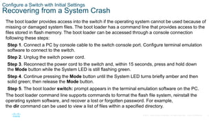
The document provides instructions for configuring initial settings on a Cisco switch, including:
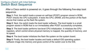
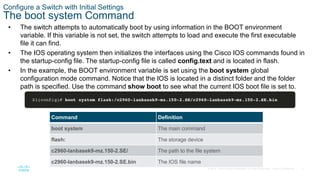
- Configuring the boot system to specify the IOS image loaded during startup.
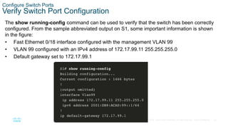
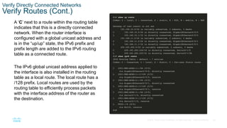
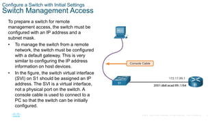
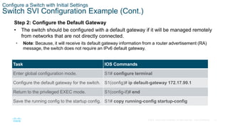
- Configuring the switch management interface by assigning an IP address to the SVI for a designated management VLAN.
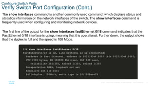
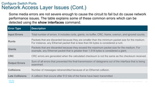
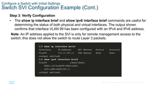
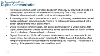
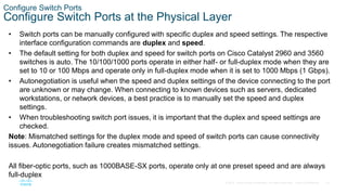
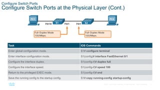
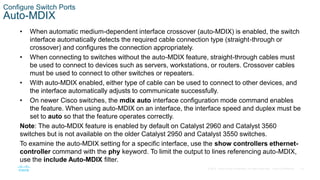
- Configuring switch ports by setting the duplex and speed settings, enabling auto-MDIX, and verifying the port configuration and status using commands like show interfaces.

![19
© 2016 Cisco and/or its affiliates. All rights reserved. Cisco Confidential
Configure Switch Ports
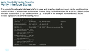
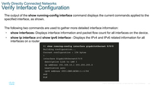
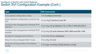
Switch Verification Commands
Task IOS Commands
Display interface status and configuration. S1# show interfaces [interface-id]
Display current startup configuration. S1# show startup-config
Display current running configuration. S1# show running-config
Display information about flash file system. S1# show flash
Display system hardware and software status. S1# show version
Display history of command entered. S1# show history
Display IP information about an interface.
S1# show ip interface [interface-id]
OR
S1# show ipv6 interface [interface-id]
Display the MAC address table.
S1# show mac-address-table
OR
S1# show mac address-table](https://image.slidesharecdn.com/module1basicdeviceconfiguration-221212042907-68707b67/85/Module-1-Basic-Device-Configuration-pptx-19-320.jpg)