Download as PDF, PPTX

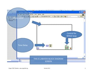
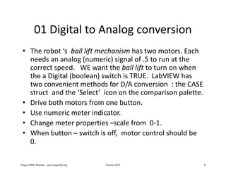
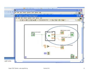
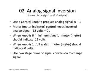
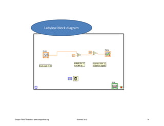
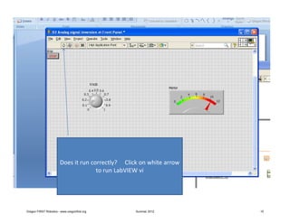

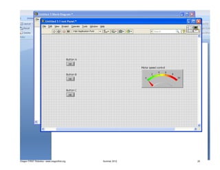
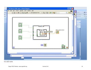

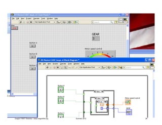
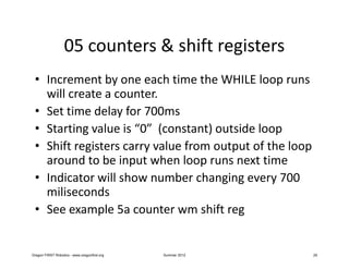
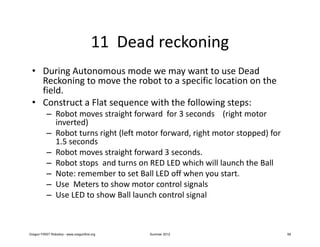
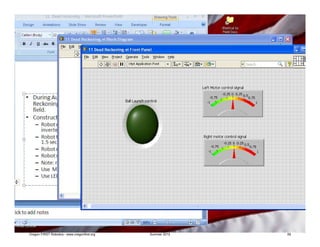
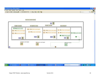
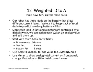
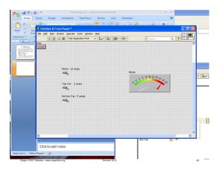
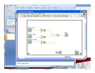

The document provides an introduction and overview of homework exercises for a 2012 summer LabVIEW class for FIRST Robotics teams. It outlines general guidelines for constructing programs using WHILE loops, stop buttons, and time delays. It then provides examples of different programming concepts to practice, including digital to analog conversion, analog signal inversion, analog signals with gate enables, nested CASE structures, and counters with shift registers. The goal is for students to become familiar with LabVIEW programming mechanics and logic commonly used in robotic systems through a series of exercises.