Download as PDF, PPTX

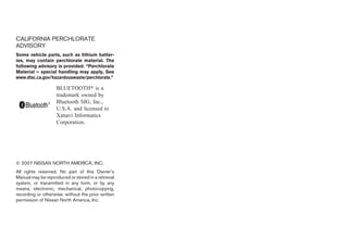

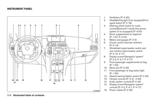

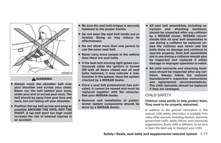

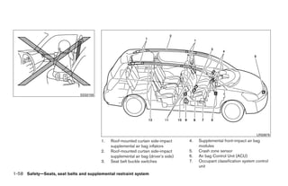
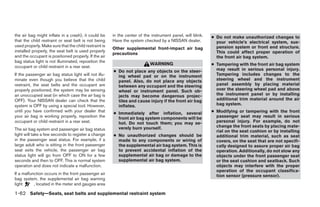

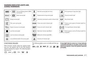

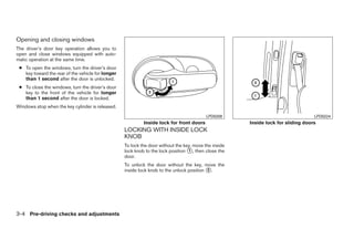
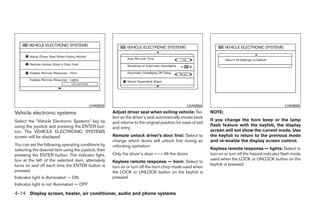
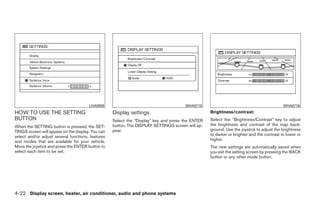
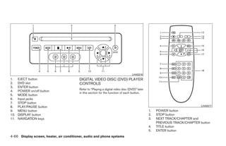
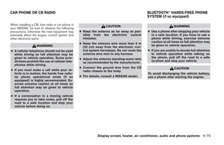
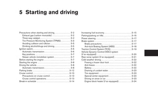
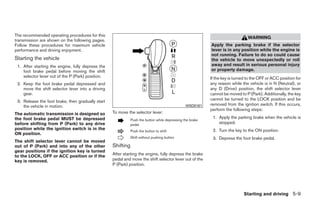
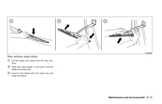
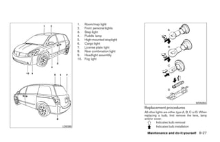
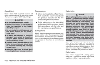
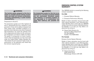
![13. AUDIO button [BASS, MID, TREBLE,
FADE, BALANCE and SSV (if so
equipped)]
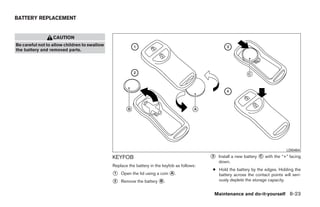
14. CD eject button
15. AUX jack
16. CD insert slot
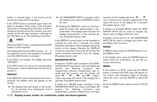
*No satellite radio reception is available
and “NO SAT” is displayed when the
SAT button is pressed unless optional
satellite receiver and antenna are
installed, and an XMா satellite radio
service subscription is active. Satellite
radio not available in Alaska, Hawaii and
Guam.
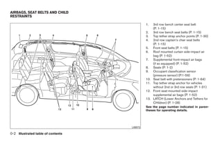
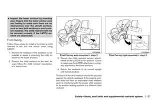
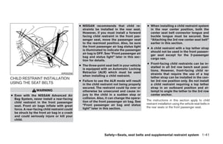
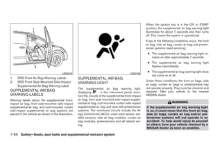
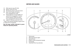
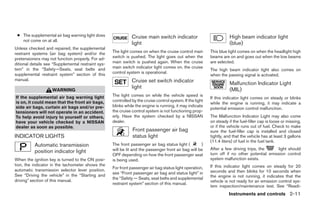
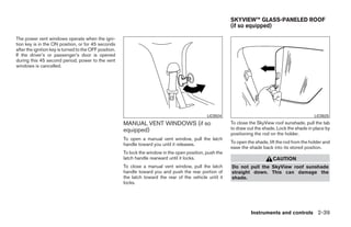
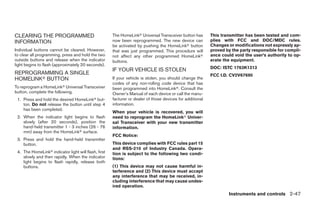
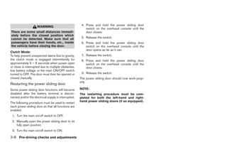
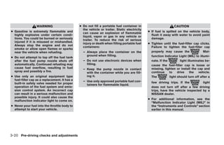
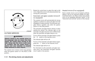
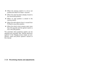
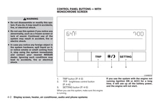
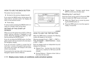
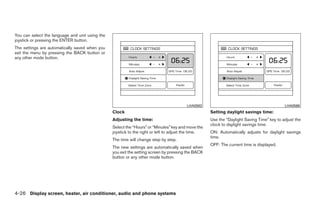
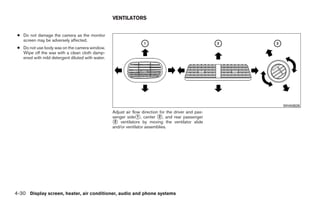
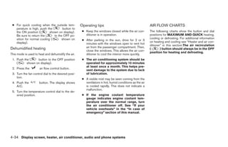
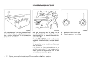
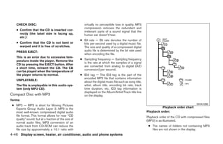
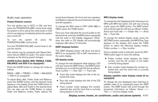
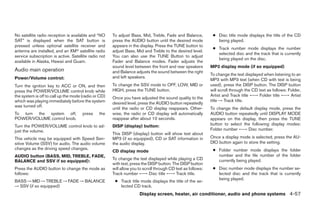
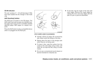
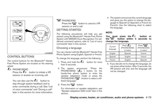
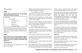
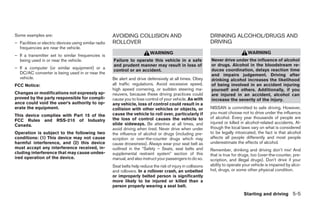
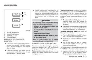
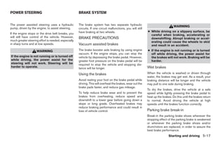
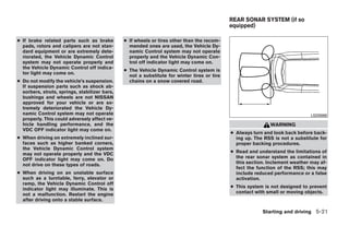
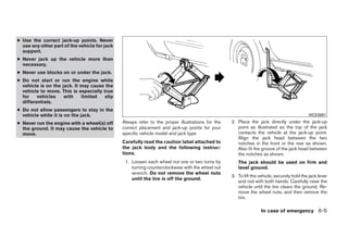
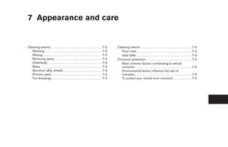
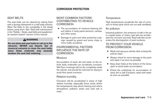
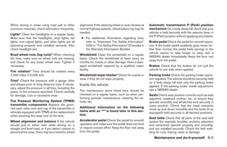
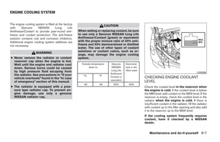
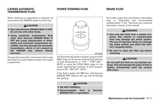
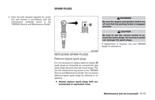
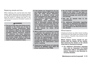
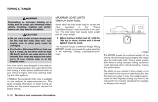
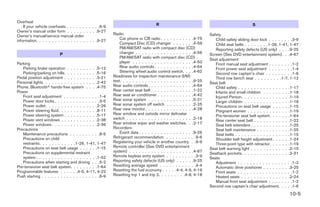
FM/AM/SAT RADIO WITH
COMPACT DISC (CD) PLAYER
For all operation precautions, see ЉAudio opera-
tion precautionsЉ earlier in this section.
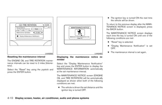
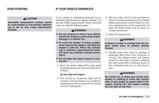
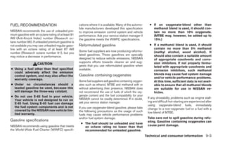
LHA0634 No satellite radio reception is available and “NO
1. SEEK/TRACK button 7. AUX button SAT” is displayed when the SAT button is
pressed unless optional satellite receiver and
2. PRESET A·B·C button 8. TUNE/CAT button
antenna are installed, and an XMா satellite radio
3. CD/DVD button 9. DISP button
service subscription is active. Satellite radio not
4. Station select (1 - 6) buttons 10. FM·AM/SAT (satellite) radio button* available in Alaska, Hawaii and Guam.
5. POWER/VOLUME control knob 11. SCAN/RPT button
6. REAR CTRL button 12. Rear speaker control button
4-50 Display screen, heater, air conditioner, audio and phone systems
੬ REVIEW COPY—2008 Quest (van)
Owners Manual—USA_English (nna)
06/29/07—debbie ੭](https://image.slidesharecdn.com/2008-quest-120818113208-phpapp02/85/2008-QUEST-OWNER-S-MANUAL-213-320.jpg)
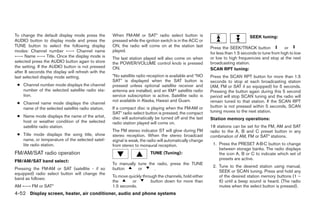
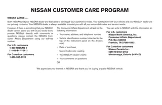
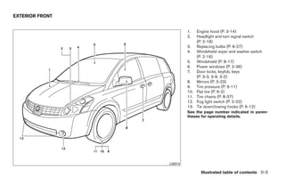
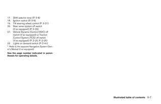
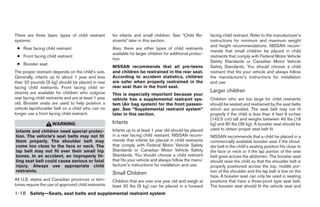
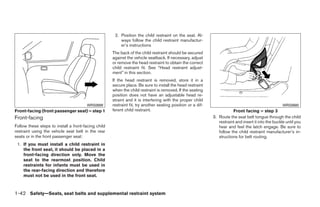
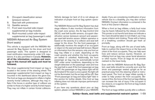
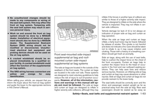
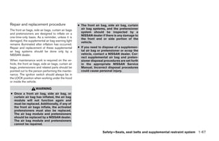
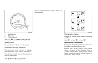
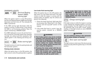
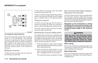
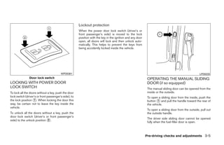
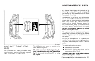
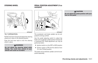
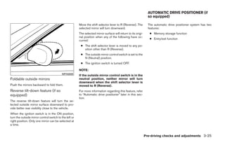
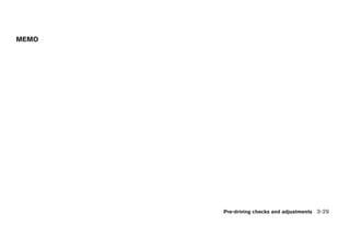
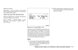
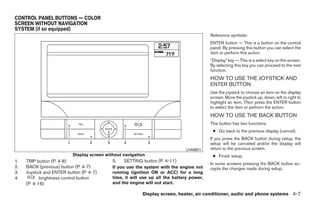
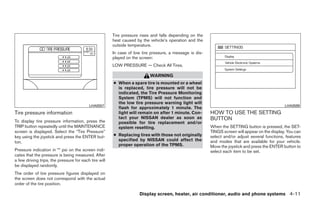
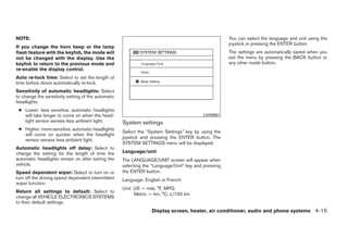
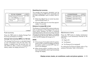
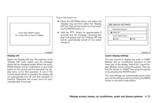
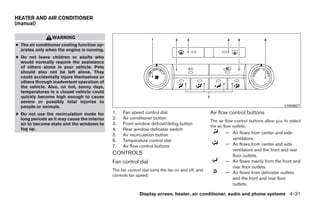
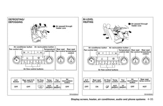
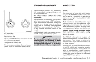
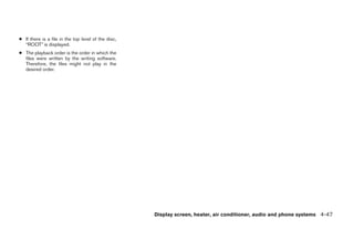
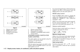
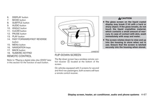
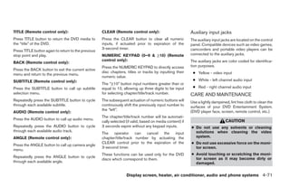
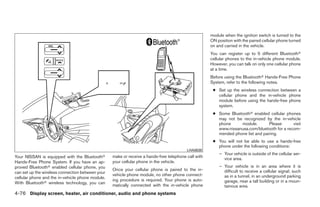
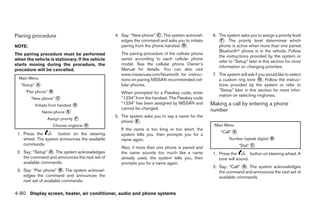
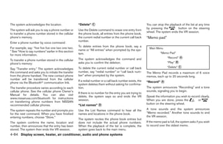
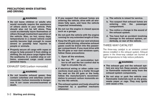
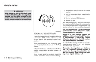
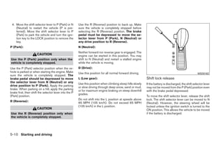
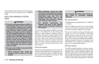
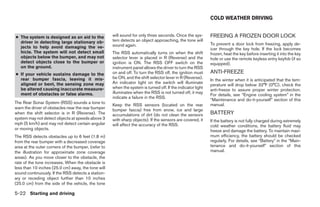
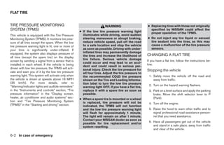
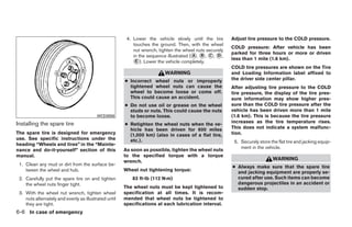
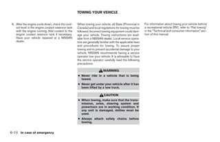
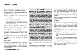
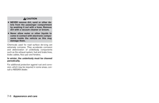
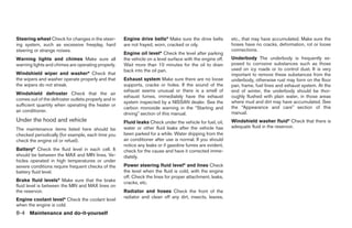
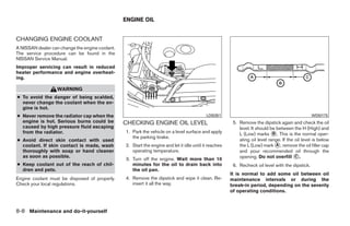
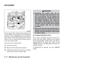
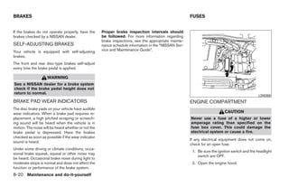
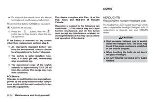
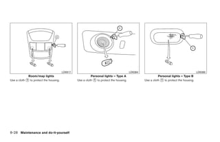
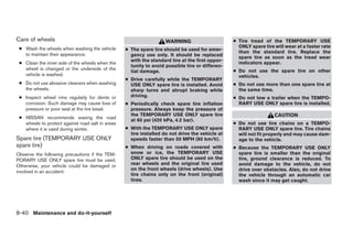
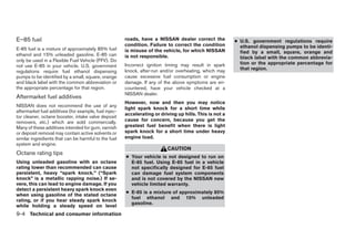
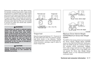
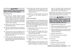
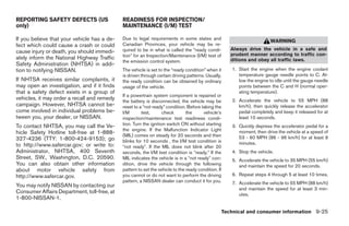
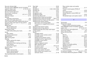
![11. SCAN/RPT button
12. Rear speaker control button
13. AUDIO button [BASS, MID, TREBLE,
FADE, BALANCE and SSV (if so
equipped)]
14. CD load button
15. CD eject button
16. CD insert slot
17. AUX jack
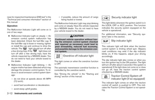
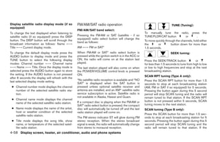
*No satellite radio reception is available
and “NO SAT” is displayed when the
SAT button is pressed unless optional
satellite receiver and antenna are
installed, and an XMா satellite radio
service subscription is active. Satellite
radio not available in Alaska, Hawaii and
Guam.
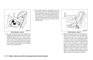
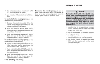
LHA0635
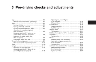
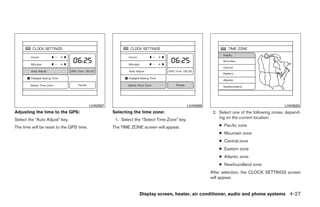
Type A
1. SEEK/TRACK button 6. REAR CTRL button
2. PRESET A·B·C button 7. AUX button
3. CD/DVD button 8. TUNE/FLDR·CAT button
4. Station and CD select (1 - 6) buttons 9. DISP button
5. POWER/VOLUME control knob 10. FM·AM/SAT (satellite) radio button*
Display screen, heater, air conditioner, audio and phone systems 4-55
੬ REVIEW COPY—2008 Quest (van)
Owners Manual—USA_English (nna)
06/29/07—debbie ੭](https://image.slidesharecdn.com/2008-quest-120818113208-phpapp02/85/2008-QUEST-OWNER-S-MANUAL-218-320.jpg)
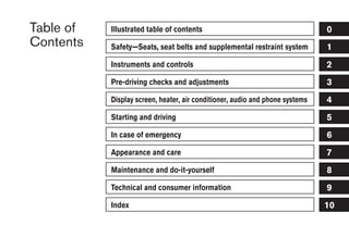
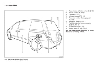
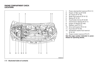
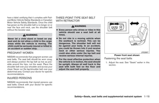
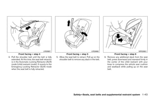
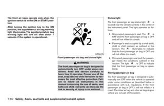
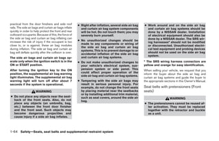
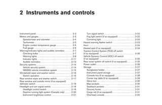
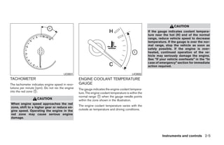
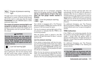
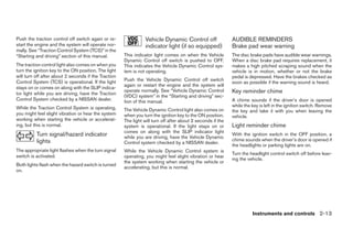
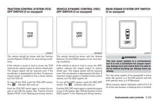
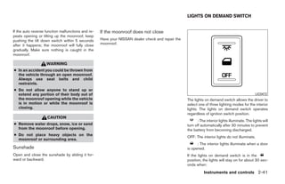
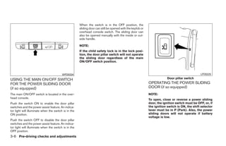
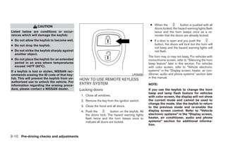
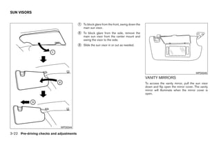
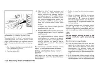
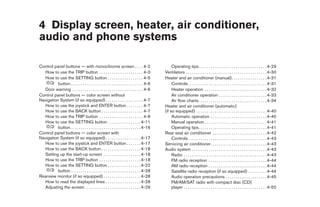
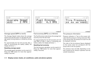
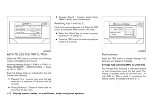
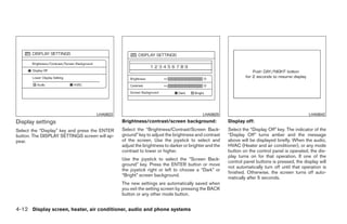
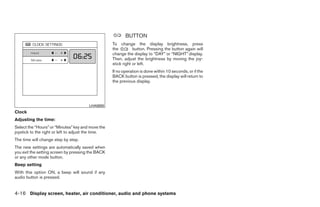
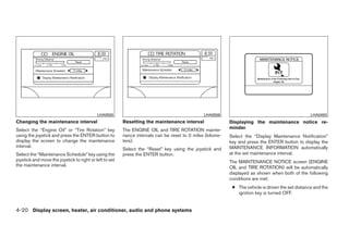
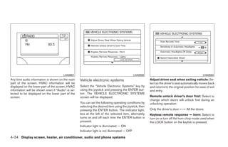
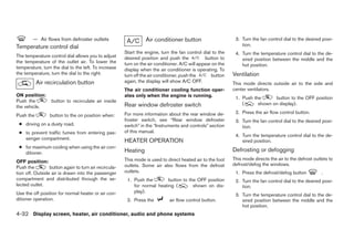
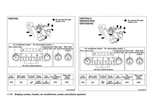
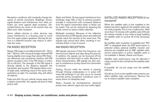
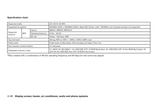
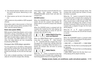
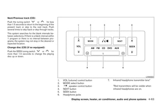
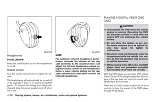
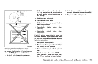
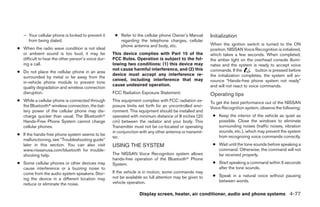
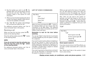
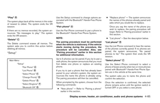
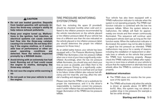
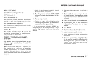
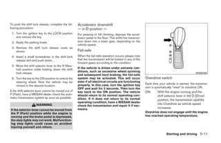
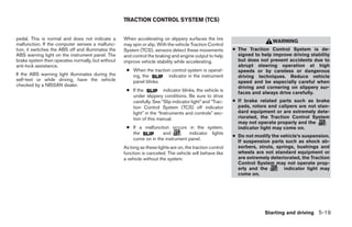
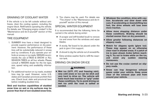
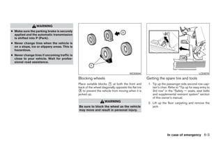
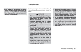
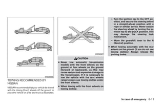
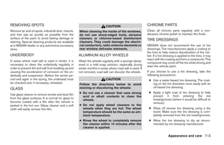
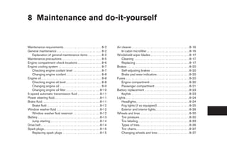
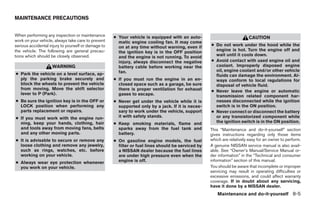
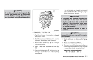
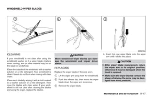
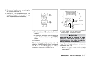
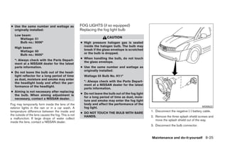
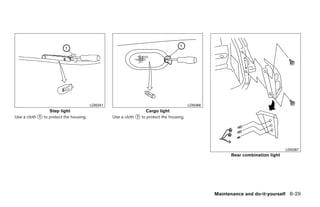
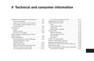
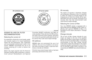
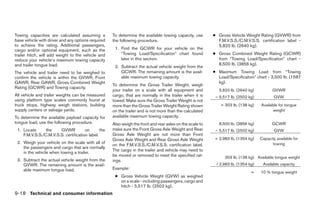
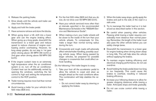
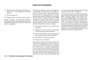
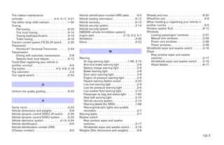
![11. FM·AM/SAT (satellite) radio select
button*
12. Rear speaker control button
13. RPT·RDM button
14. AUDIO button [BASS, MID, TREBLE,
FADE, BALANCE and SSV (if so
equipped)]
15. CD load button
16. CD eject button
17. CD insert slot
18. AUX jack
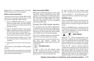
*No satellite radio reception is available
and “NO SAT” is displayed when the
SAT button is pressed unless optional
satellite receiver and antenna are
installed, and an XMா satellite radio
service subscription is active. Satellite
radio not available in Alaska, Hawaii and
Guam.
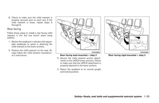
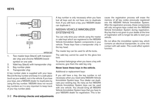
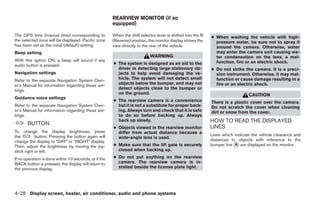
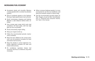
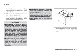
LHA0636 FM/AM/SAT RADIO WITH
Type B COMPACT DISC (CD) CHANGER
1. SEEK/TRACK button 6. REAR CTRL button (Type A and B) (if so equipped)
2. PRESET A·B·C button 7. AUX button
3. CD/DVD button 8. TUNE/FLDR·CAT button For all operation precautions, see ЉAudio opera-
4. Station and CD select (1 - 6) buttons 9. DISP button tion precautionsЉ earlier in this section.
5. POWER/VOLUME control knob 10. SCAN button
4-56 Display screen, heater, air conditioner, audio and phone systems
੬ REVIEW COPY—2008 Quest (van)
Owners Manual—USA_English (nna)
06/29/07—cathy ੭](https://image.slidesharecdn.com/2008-quest-120818113208-phpapp02/85/2008-QUEST-OWNER-S-MANUAL-219-320.jpg)
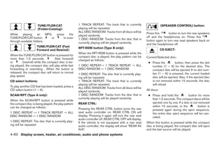
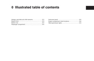
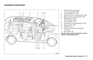
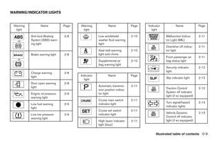
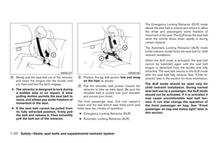
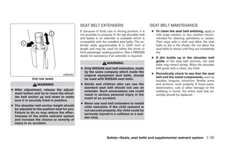
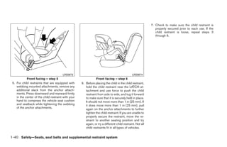
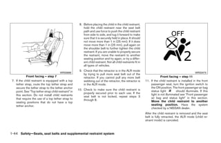
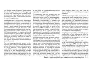
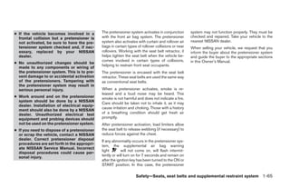
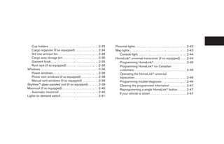
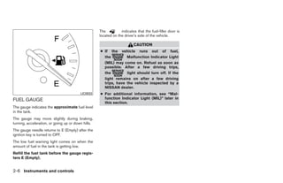
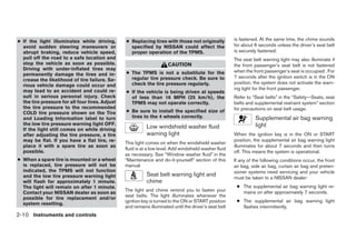
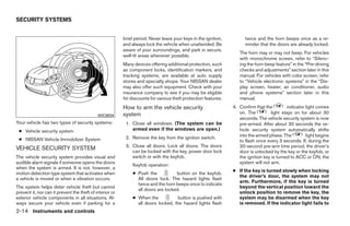
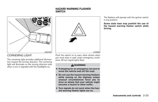
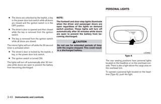
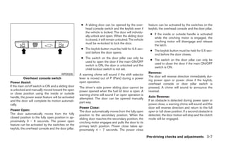
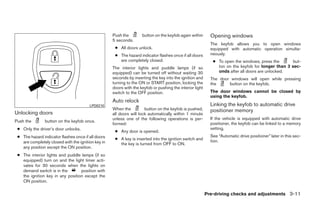
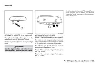
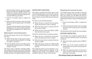
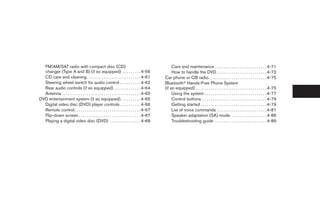
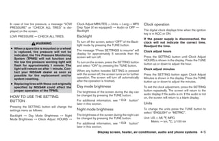
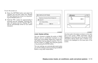
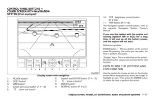
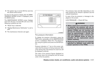
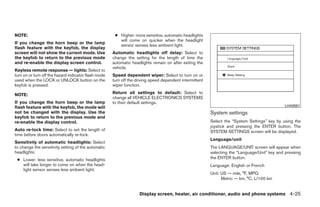
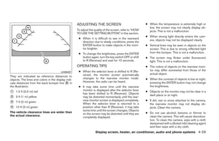
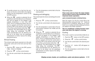
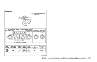
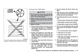
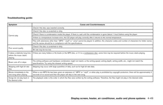
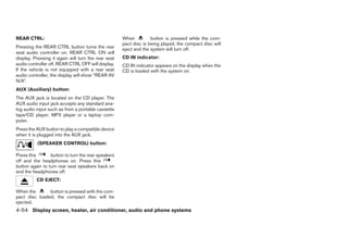
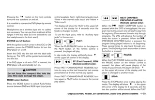
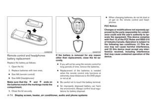
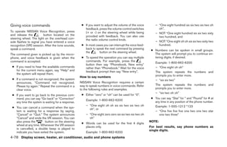
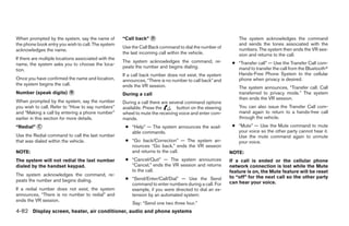
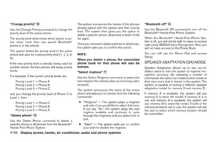
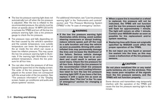
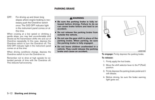
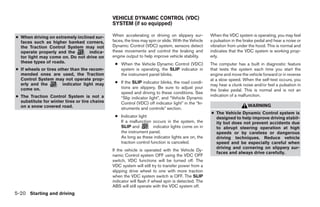
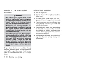
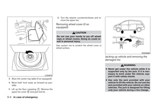
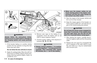
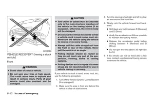
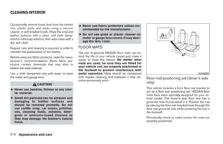
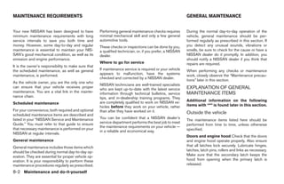
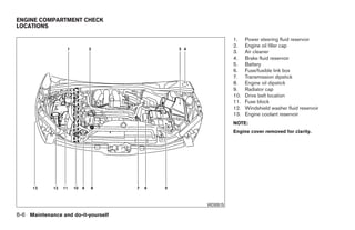
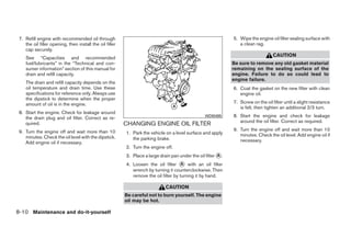
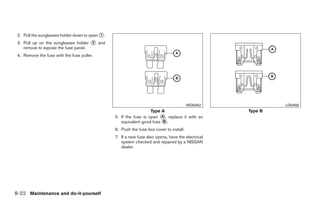
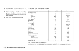
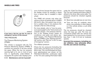
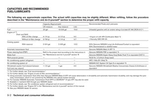
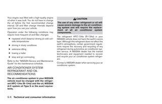
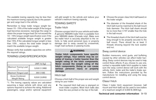
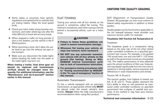
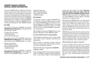
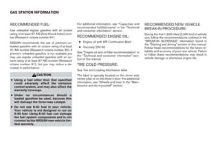
![DVD ENTERTAINMENT SYSTEM (if so
equipped)
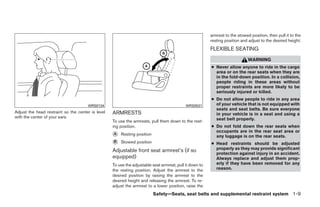
ANTENNA CAUTION
Window antenna
● The glass screen on the liquid crystal
The antenna pattern is printed inside the rear display may break if hit with a hard or
passenger and driver side windows. sharp object. If the glass breaks, do not
touch the liquid crystalline material,
CAUTION which contains a small amount of mer-
cury. In case of contact with skin, wash
● Do not place metalized film near the immediately with soap and water.
rear driver or passenger side window
glass or attach any metal parts to it. This ● Use a damp, soft cloth when cleaning
may cause poor reception or noise. the DVD Entertainment System compo-
nents. Do not use solvents or cleaning
● When cleaning the inside of the rear solutions.
driver or passenger side window, be
careful not to scratch or damage the LHA0641 ● To avoid discharging the vehicle bat-
window antenna. Lightly wipe along the tery, do not operate the system more
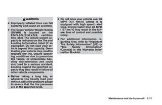
antenna with a dampened soft cloth. WARNING than 15 minutes without starting the
engine.
● The DVD Entertainment System is de-
signed for rear seat passenger viewing Do not attempt to use the system in extreme
only. temperature conditions [below -4°F (-20°C) or
● The driver must not attempt to operate above 158°F (70°C)]
the DVD Entertainment System while
the vehicle is in motion so that full at-
tention may be given to vehicle
operation.
Display screen, heater, air conditioner, audio and phone systems 4-65
੬ REVIEW COPY—2008 Quest (van)
Owners Manual—USA_English (nna)
06/29/07—debbie ੭](https://image.slidesharecdn.com/2008-quest-120818113208-phpapp02/85/2008-QUEST-OWNER-S-MANUAL-228-320.jpg)
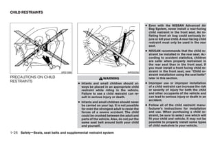
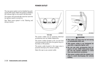
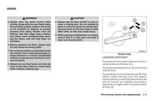
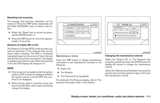
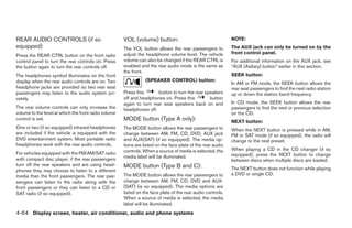
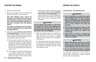
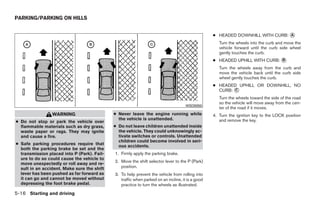
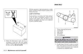
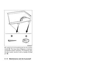
![Do not attempt to use the system in extreme ● A new disc may be rough on its inner
temperature conditions [below -4°F (-20°C) or and outer edges. Remove the rough
above 158°F (70°C)] edges using the side of a pen or pencil
Do not attempt to operate the system in extreme as illustrated.
humidity conditions (less than 10% or more than ● Never attempt to use a DVD that has
75%). been cracked, deformed, or repaired
using adhesive. Doing so may cause
damage to the equipment.
● Handle the DVD carefully to avoid contami-
nation or flaws. Otherwise, signals may not
be read properly.
● Do not write, draw or attach anything on any
LHA0049 side of the DVD.
HOW TO HANDLE THE DVD ● Do not store the DVD in locations with direct
sunlight or in high temperatures or humidity.
CAUTION ● Always place discs in the storage case when
● Handle a DVD by its edges. Never touch they are not being used.
the surface of the disc. ● Do not put on any sticker or write anything
● To clean a disc, wipe the surface from on either surface of the DVD.
the center to the outer edge using a
clean, soft cloth. Do not wipe the disc
using a circular motion.
● Do not use a conventional record
cleaner, benzine, thinner or alcohol in-
tended for industrial use.
4-72 Display screen, heater, air conditioner, audio and phone systems
੬ REVIEW COPY—2008 Quest (van)
Owners Manual—USA_English (nna)
06/29/07—debbie ੭](https://image.slidesharecdn.com/2008-quest-120818113208-phpapp02/85/2008-QUEST-OWNER-S-MANUAL-235-320.jpg)


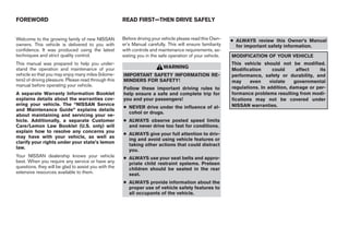
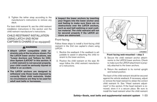
This document is the owner's manual for the 2008 Nissan Quest, providing essential safety and operational guidelines for new vehicle owners. It emphasizes the importance of reading the manual before driving, adhering to safety rules, and not modifying the vehicle, as modifications may lead to safety issues and void warranties. Additionally, it includes information on available warranties, customer care programs, and provides instructions for operating vehicle features and maintenance.