Downloaded 81 times


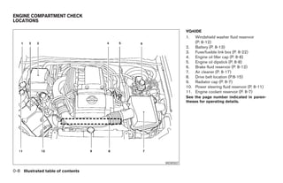
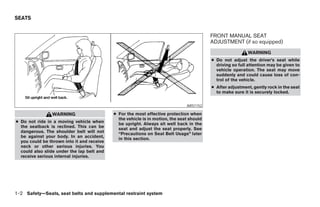
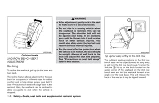


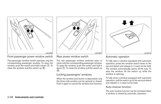

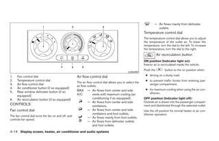
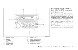
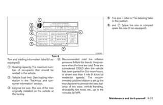
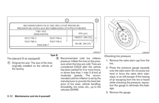
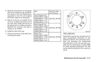
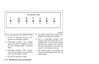
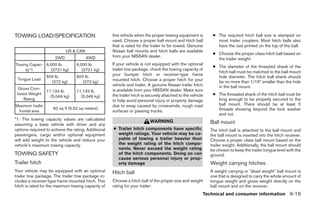
![LHA0567 LHA0568 LHA0563
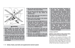
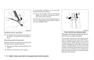
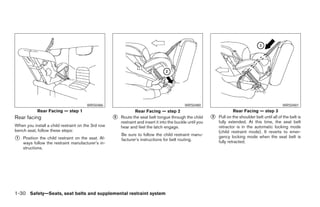
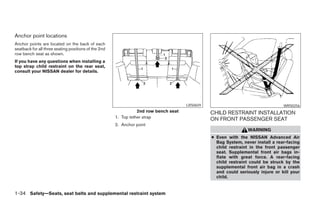
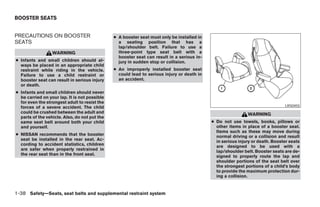
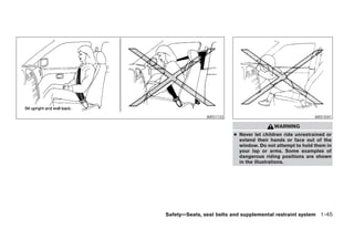
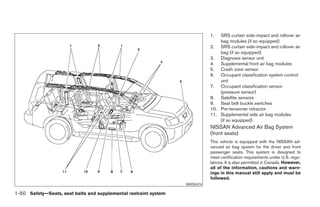
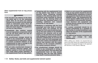
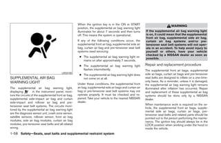
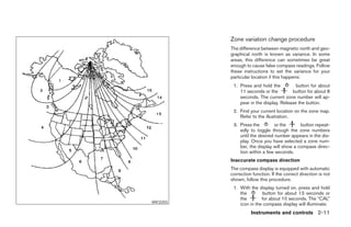
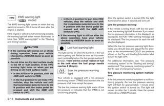
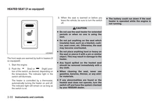
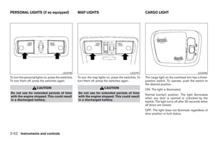
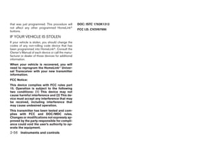
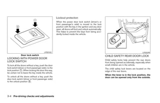
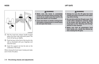
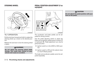
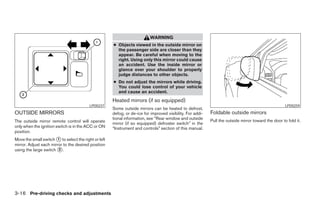
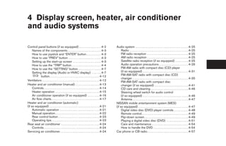
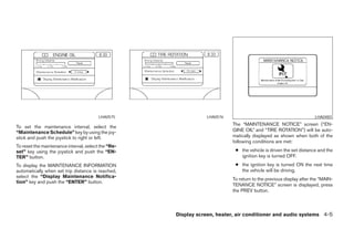
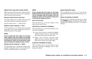
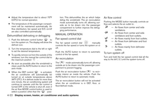
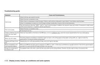
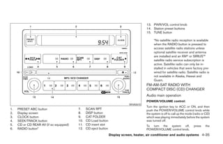
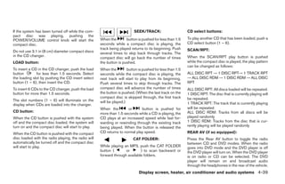
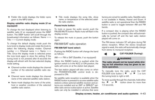
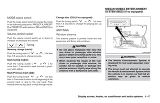
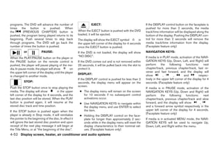
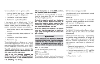
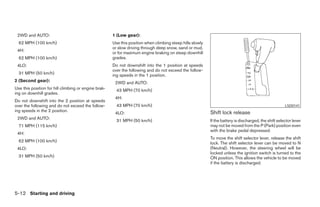
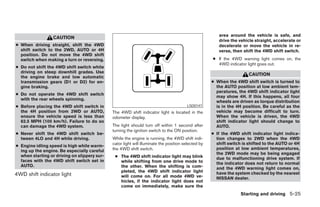
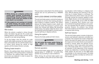
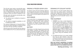
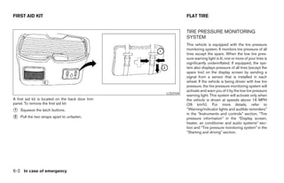
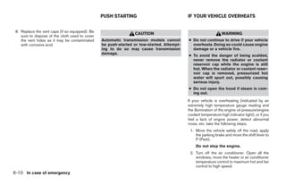
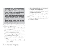
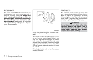
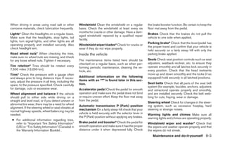
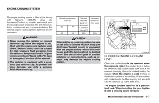
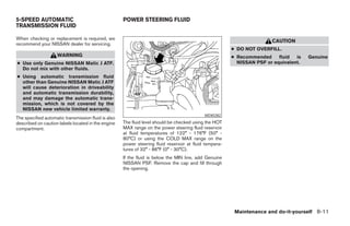
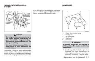
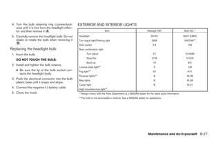
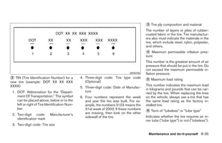
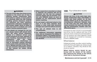
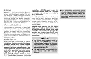
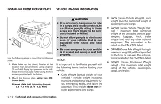
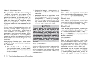
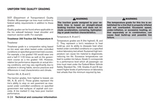
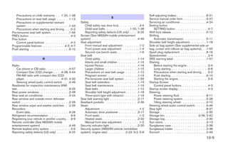
Adjusting the time to the GPS: Selecting the time zone: 2. Select one of the following zones depending
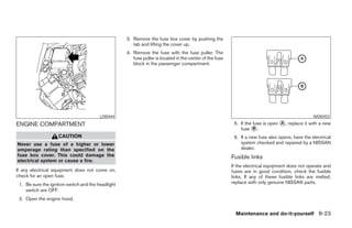
Select the “Auto Adjust” key. 1. Select the “Select Time Zone” key. on the current location.
The time will be reset to the GPS time. The [TIME ZONE] screen will appear. ● Pacific zone
● Mountain zone
● Central zone
● Eastern zone
● Atlantic zone
● Newfoundland zone
After selection, the [CLOCK SETTINGS] screen
will appear.
Display screen, heater, air conditioner and audio systems 4-11
੬ REVIEW COPY—2006 Pathfinder (pat)
Owners Manual—USA_English (nna)
08/19/05—rhinson ੭](https://image.slidesharecdn.com/2006-path-120818112946-phpapp01/85/2006-PATHFINDER-OWNER-S-MANUAL-164-320.jpg)
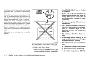

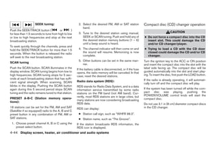
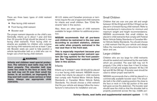
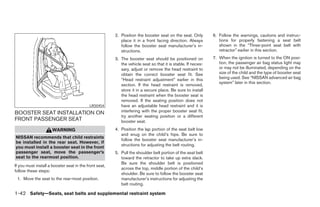
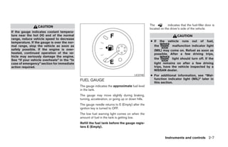
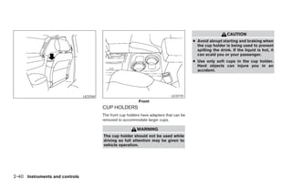
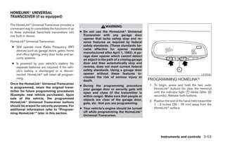
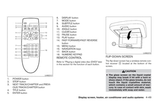
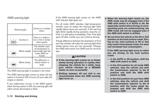
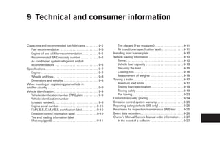
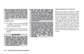
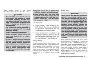
![CAUTION
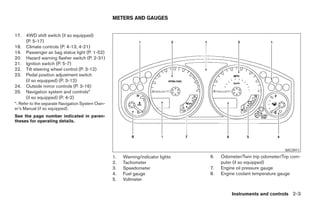
● The glass screen on the liquid crystal
display may break if hit with a hard or
sharp object. If the glass breaks, do not
touch the liquid crystalline material,
which contains a small amount of mer-
cury. In case of contact with skin, wash
immediately with soap and water.
● Use a damp, soft cloth when cleaning
the Mobile Entertainment System com-
ponents. Do not use solvents or clean-
ing solutions.
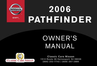
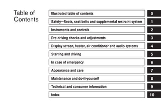
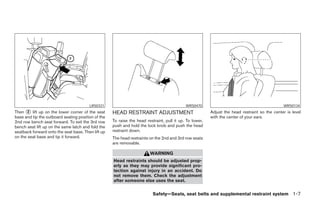
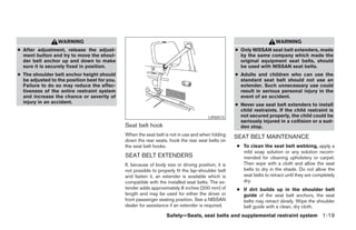
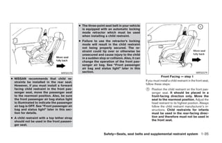
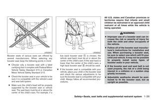
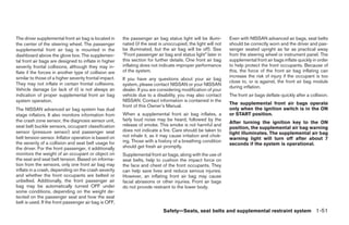
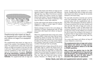
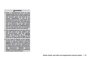
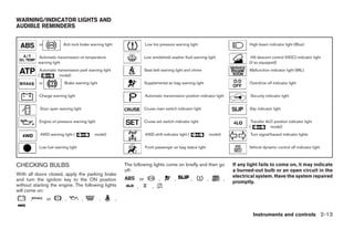
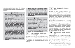
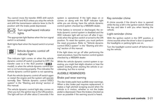
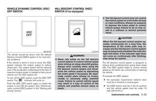
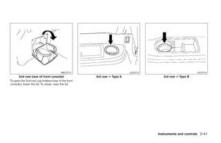
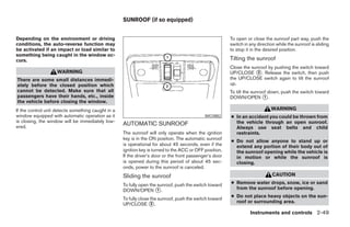
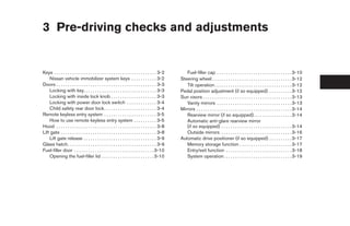
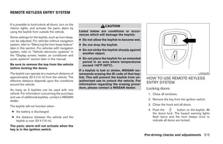
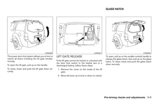
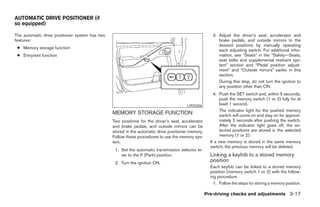
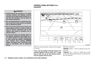
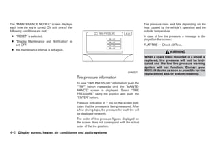
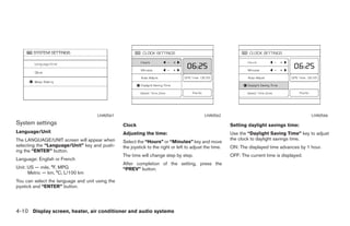
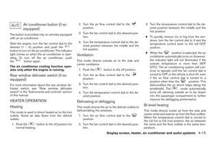
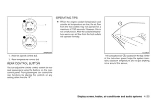
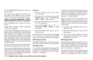
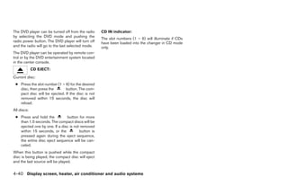
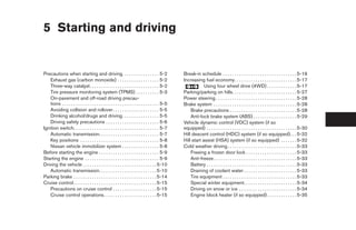
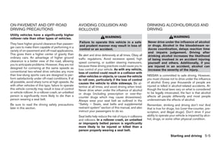
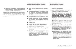
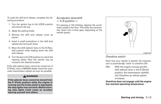
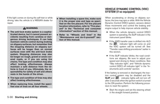
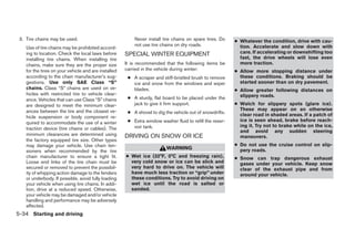
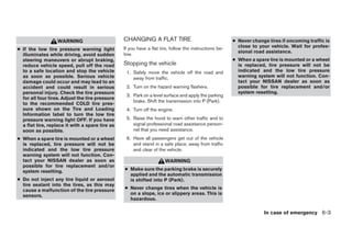
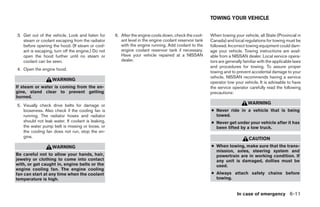
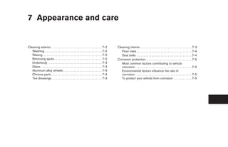
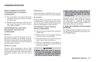
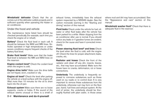
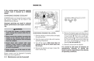
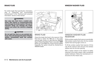
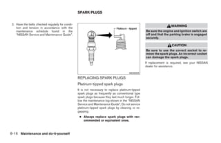
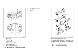
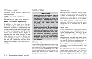
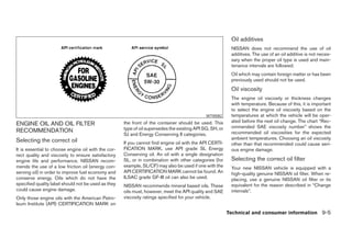
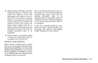
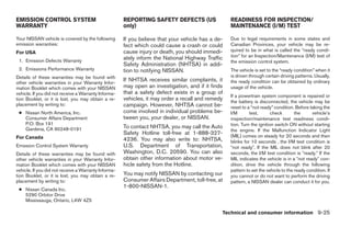
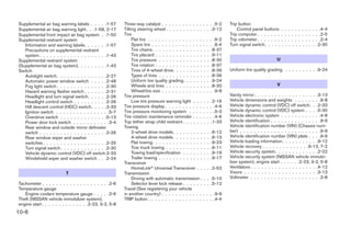
● Do not attempt to use the system in LHA0316
extreme temperature conditions [below
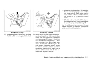
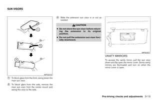
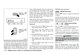
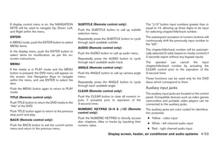
-4°F (-20°C) or above 158°F (70°C)]. 1. EJECT button DIGITAL VIDEO DISC (DVD) PLAYER
2. DVD slot CONTROLS
● To avoid draining the vehicle battery, do 3. ENTER button
not operate the system more than 15 Refer to “Playing a digital video disc (DVD)” later
minutes without starting the engine. 4. POWER on/off button
in this section for the function of each button.
5. MODE button
6. Input jacks
7. STOP button
8. PLAY/PAUSE button
9. MENU button
10. DISPLAY button
11. NAVIGATION keys
4-48 Display screen, heater, air conditioner and audio systems
੬ REVIEW COPY—2006 Pathfinder (pat)
Owners Manual—USA_English (nna)
07/29/05—cathy ੭](https://image.slidesharecdn.com/2006-path-120818112946-phpapp01/85/2006-PATHFINDER-OWNER-S-MANUAL-201-320.jpg)
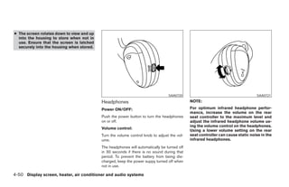
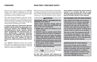
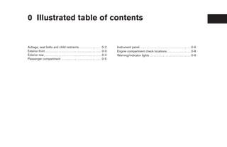
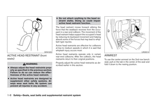
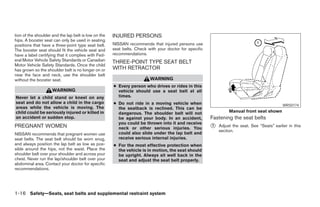
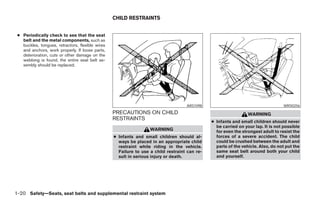
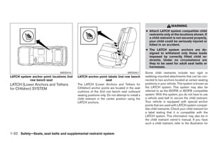
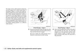
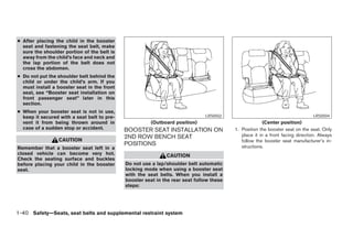
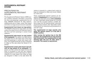
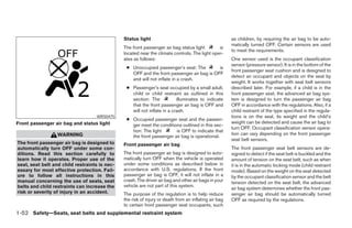
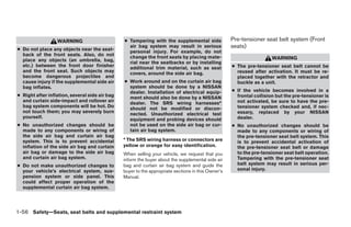
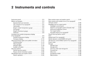
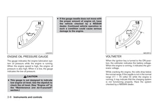
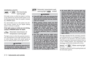
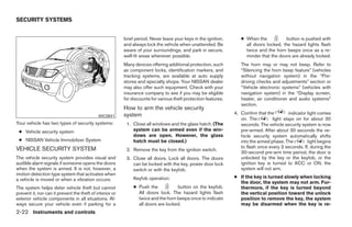
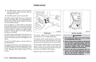
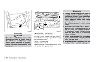
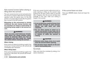
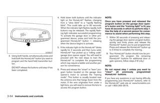
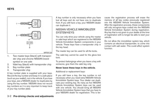
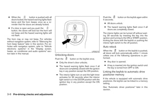
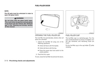
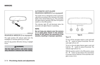
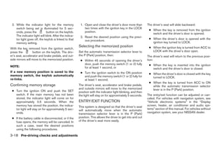
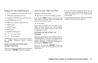
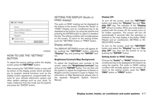
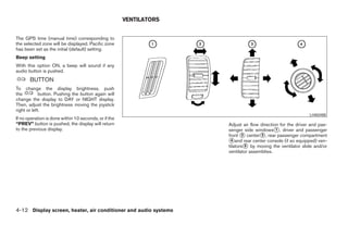
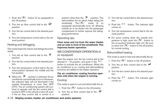
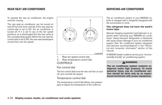
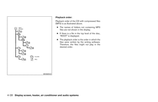
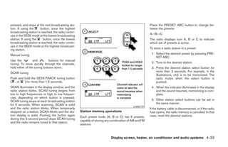
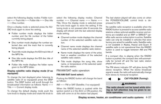
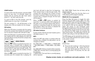
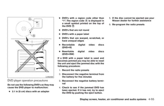
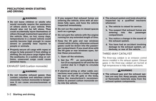
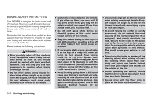
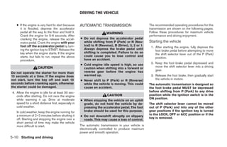
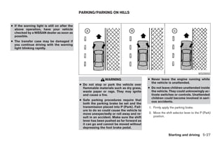
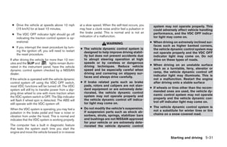
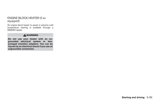
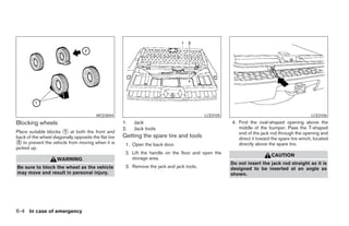
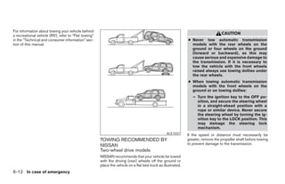
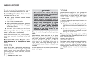
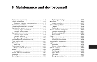
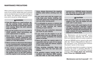
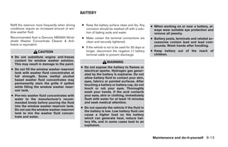
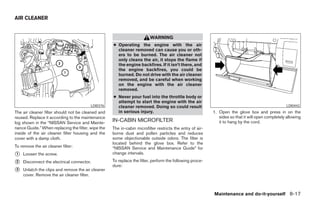
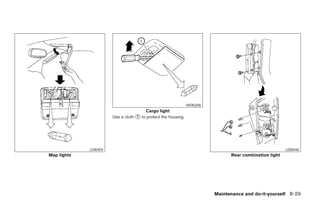
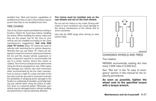
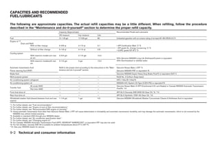
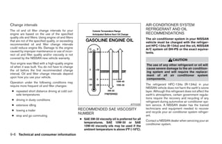
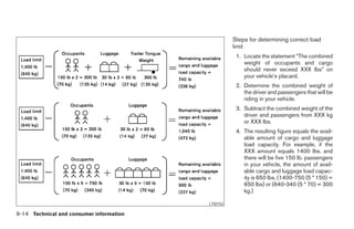
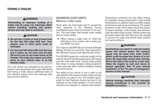
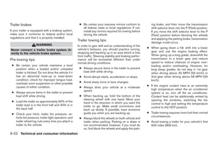
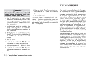
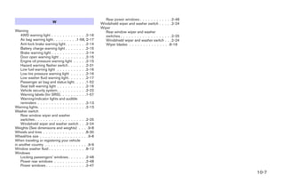
![CARE AND MAINTENANCE ● A new disc may be rough on its inner
Use a lightly dampened, lint free cloth to clean the and outer edges. Remove the rough
surfaces of your NISSAN mobile entertainment edges using the side of a pen or pencil
system. (DVD player face, screen, remote con- as illustrated.
trol, etc.) ● Never attempt to use a DVD that has
been cracked, deformed, or repaired
CAUTION using adhesive. Doing so may cause
damage to the equipment.
● Do not use any solvents or cleaning
solutions when cleaning the video ● Handle the DVD carefully to avoid contami-
system. nation or flaws. Otherwise, signals may not
● Do not use excessive force on the moni- be read properly.
tor screen. ● Do not write, draw or attach anything on any
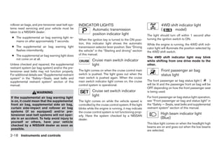
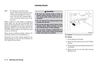
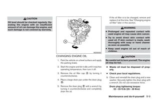
● Avoid touching or scratching the moni- LHA0049 side of the DVD.
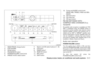
tor screen as it may become dirty or HOW TO HANDLE THE DVD ● Do not store the DVD in locations with direct
damaged. sunlight or in high temperatures or humidity.
● Do not attempt to use the system in CAUTION ● Always place discs in the storage case when
extreme temperature conditions [below they are not being used.
-4°F (-20°C) or above 158°F (70°C)]. ● Handle a DVD by its edges. Never touch
the surface of the disc. ● Do not put on any sticker or write anything
● Do not attempt to operate the system in on either surface of the DVD.
extreme humidity conditions (less than ● To clean a disc, wipe the surface from
10% or more than 75%). the center to the outer edge using a
clean, soft cloth. Do not wipe the disc
using a circular motion.
● Do not use a conventional record
cleaner, benzine, thinner or alcohol in-
tended for industrial use.
4-54 Display screen, heater, air conditioner and audio systems
੬ REVIEW COPY—2006 Pathfinder (pat)
Owners Manual—USA_English (nna)
07/29/05—cathy ੭](https://image.slidesharecdn.com/2006-path-120818112946-phpapp01/85/2006-PATHFINDER-OWNER-S-MANUAL-207-320.jpg)

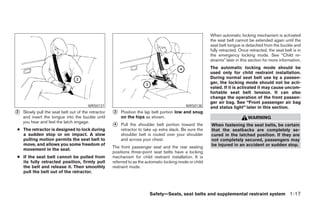
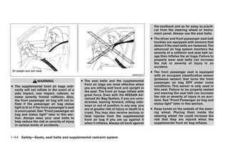
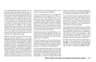
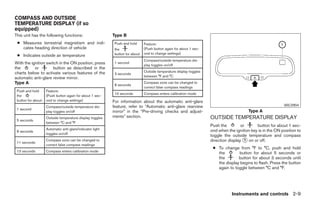
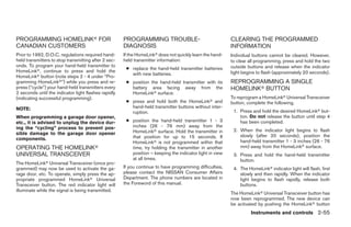
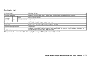
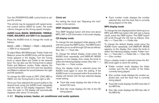
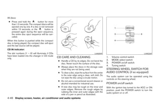
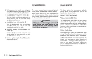
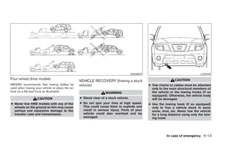
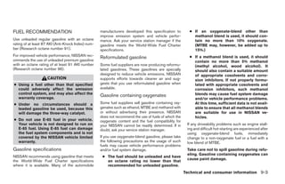
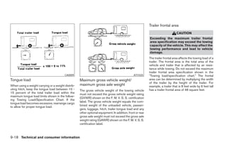
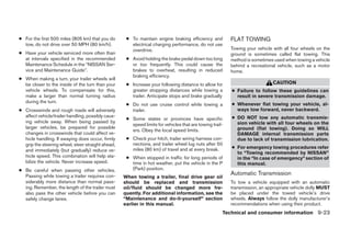
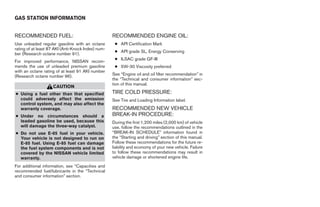
![When the vehicle is stuck,
● Set the 4WD shift switch to 4H or 4LO.
● If it is difficult to free the vehicle, repeat
forward and backward movement to in-
crease the movement.
● If the vehicle is stuck deep in mud, place
stones or wooden blocks under the tires.
Then try the recovery procedures above. Tire
chains may be effective.
CAUTION
● Do not spin the tires excessively. Tires
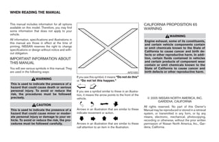
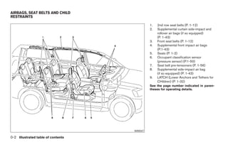
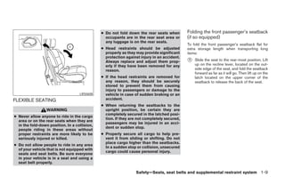
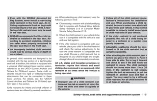
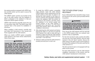
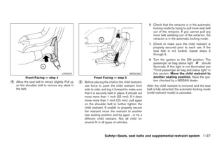
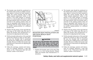
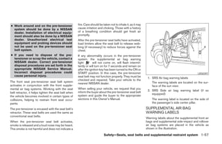
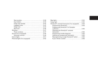
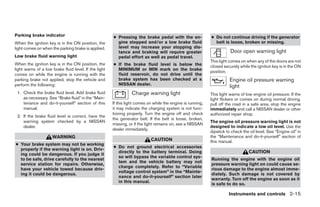
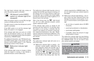
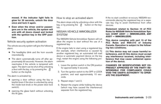
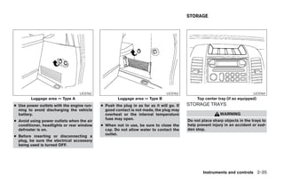
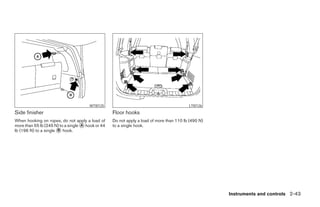
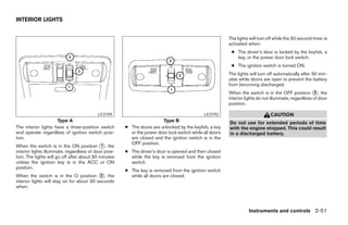
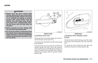
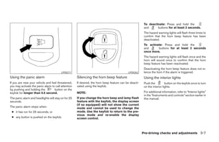
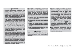
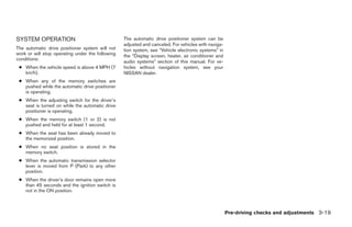
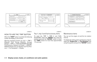
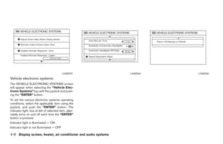
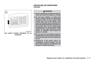
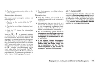
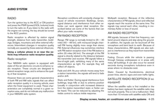
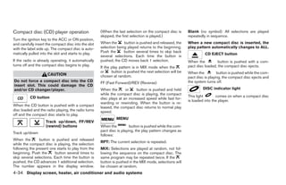
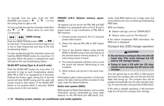
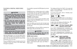
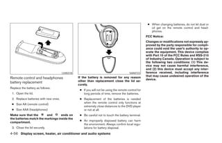
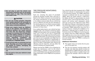
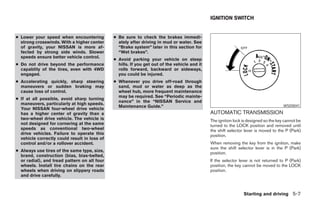
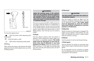
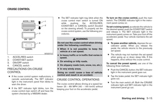
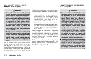
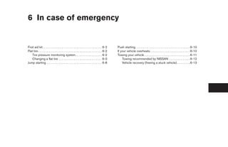
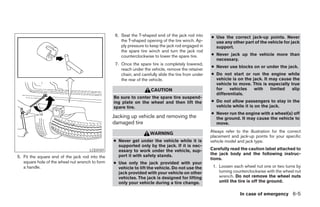
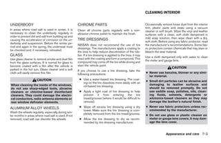
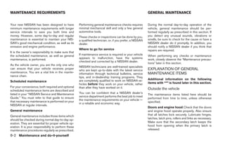
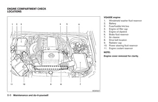
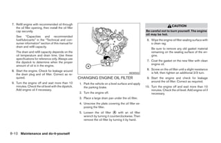
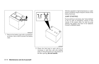
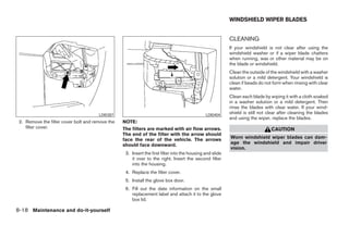
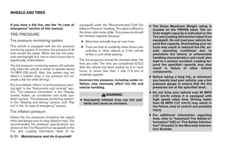
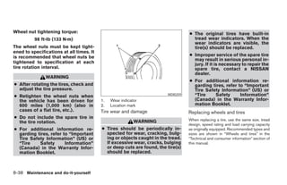
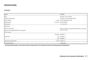
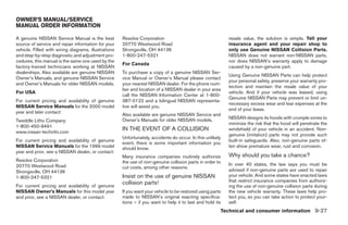
will sink deep into the mud, making it LSD0144 LSD0145
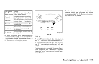
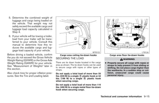
difficult to free the vehicle. Type A Type B
● Avoid shifting gears with the engine ● Shift the 4WD shift switch to either the ● If the 4WD shift switch is operated
running at high speeds as this may 2WD, AUTO (Type A only), 4H or 4LO po- while making a turn, accelerating or
cause malfunction. sition, depending on driving conditions. decelerating or if the key switch is
● With the switch set to the AUTO position turned off while in the AUTO (Type A
4WD shift switch operations only), 4H or 4LO, you may feel a jolt.
(Type A only), distribution of torque to the
front and rear wheels changes automatically, This is not abnormal.
depending on road conditions encountered ● When the vehicle is stopped after mak-
[ratio; 0 : 100 (2WD) → 50 : 50 (4WD)]. ing a turn, you may feel a slight jolt
This results in improved driving stability. after the selector lever is shifted to N or
P. This occurs because the transfer
clutch is released and not because of a
malfunction.
5-24 Starting and driving
੬ REVIEW COPY—2006 Pathfinder (pat)
Owners Manual—USA_English (nna)
08/01/05—cathy ੭](https://image.slidesharecdn.com/2006-path-120818112946-phpapp01/85/2006-PATHFINDER-OWNER-S-MANUAL-235-320.jpg)

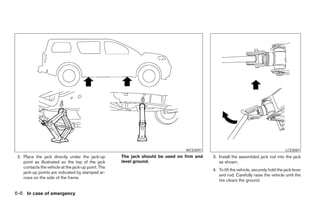
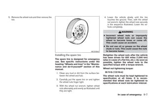
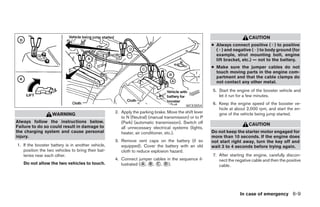


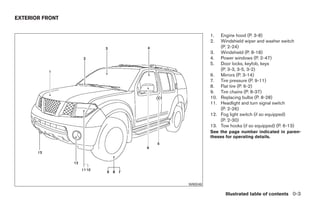
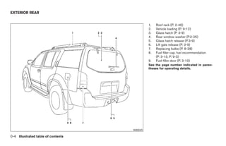
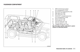
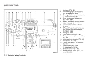
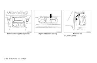
The document is the owner's manual for the 2006 Nissan Pathfinder, designed to provide essential information on vehicle operation, safety, and maintenance. It includes important instructions about driving safely, understanding vehicle controls, and adhering to safety regulations. Additionally, it covers warranties, customer service guidance, and a table of contents detailing various features and specifications of the vehicle.