Download as PDF, PPTX

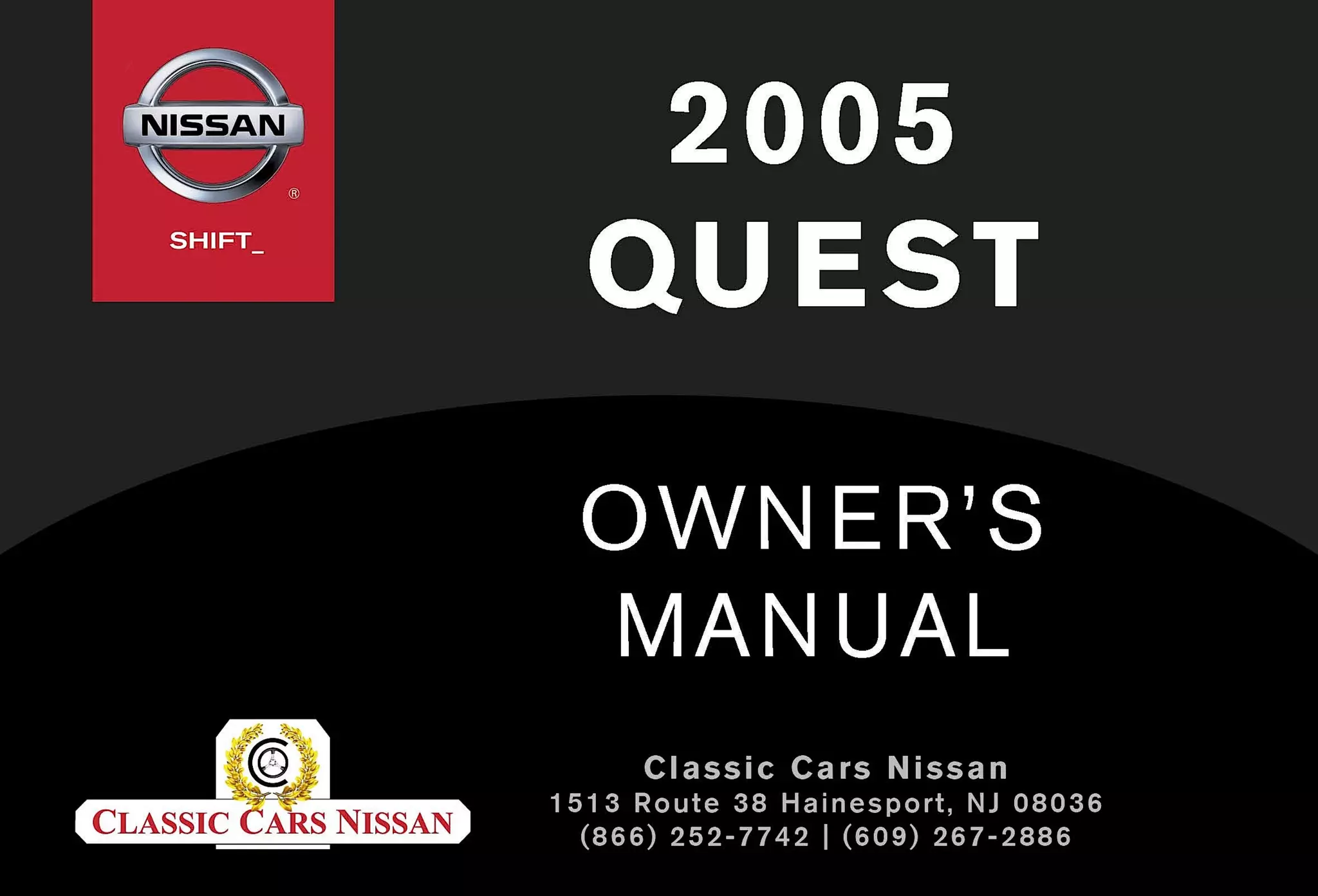

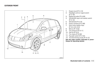
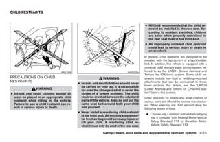

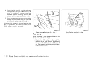
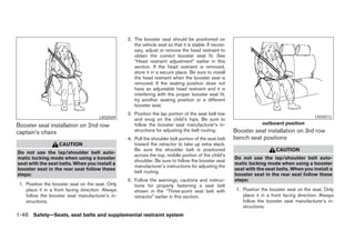
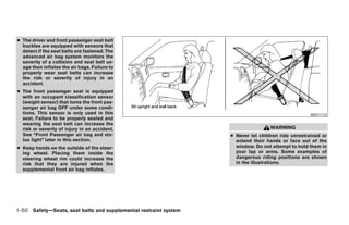
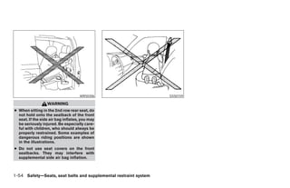
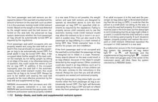
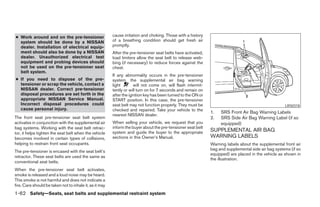

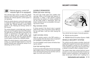
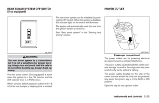
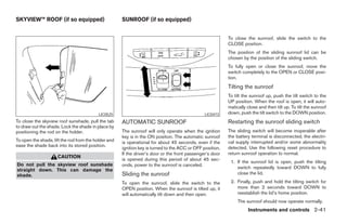
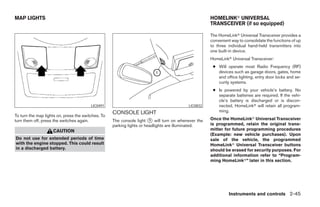
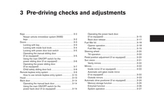
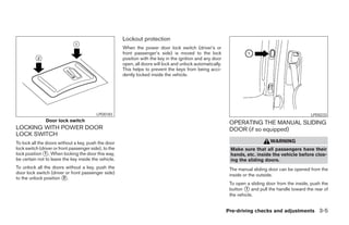
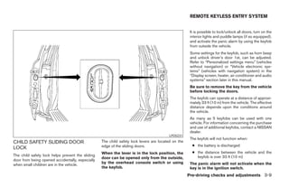
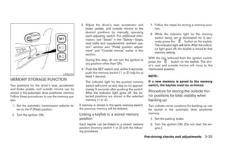
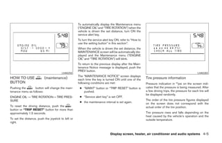
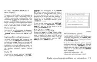
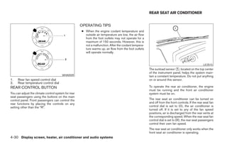
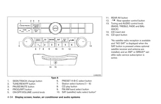
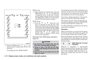
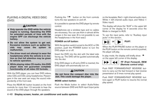
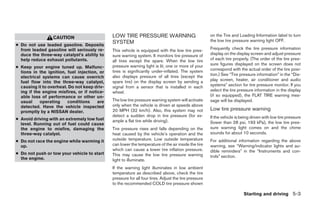
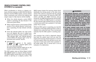
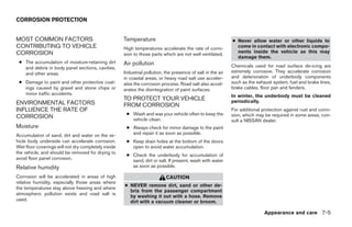
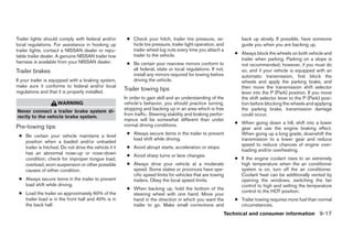
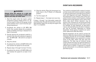
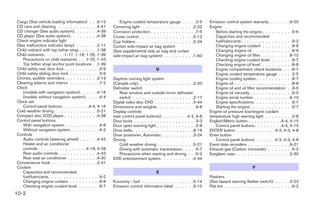
![The GPS time (manual time) corresponding to
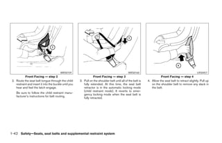
the selected zone will be displayed. Pacific zone
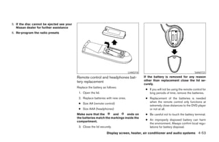
has been set as the initial (default) setting.
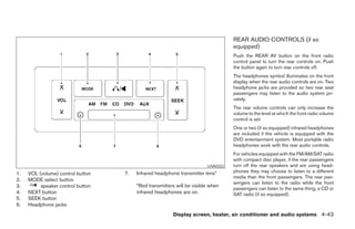
Beep setting
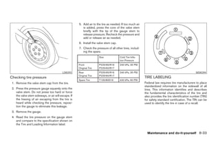
With this option ON, a beep will sound if any
audio button is pushed.
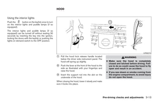
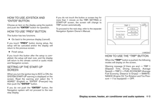
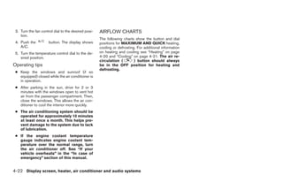
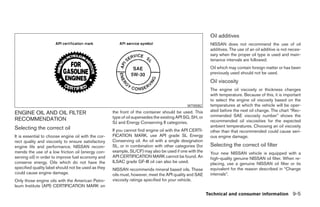
BUTTON
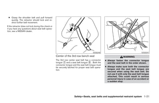
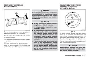
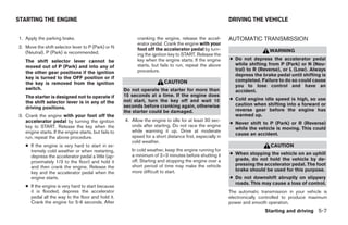
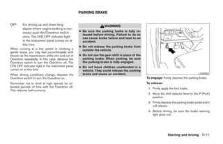
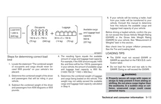
To change the display brightness, push
the button. Pushing the button again will
change the display to DAY or NIGHT display.
Then, adjust the brightness moving the joystick
right or left.
LHA0273 LHA0274
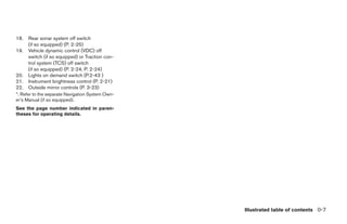
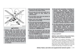
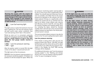
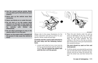
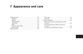
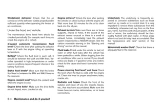
If no operation is done within 10 seconds, or if the
Selecting the time zone: 2. Select one of the following zones depending “PREV” button is pushed, the display will return
1. Select the “Select Time Zone” key. on the current location. to the previous display.
The [TIME ZONE] screen will appear. ● Pacific zone
● Mountain zone
● Central zone
● Eastern zone
● Atlantic zone
● Newfoundland zone
After selection, the [CLOCK SETTINGS] screen
will appear.
Display screen, heater, air conditioner and audio systems 4-17
੬ REVIEW COPY—2005 Quest (van)
Owners Manual—USA_English (nna)
07/21/04—debbie ੭](https://image.slidesharecdn.com/2005-quest-120818112849-phpapp01/85/2005-QUEST-OWNER-S-MANUAL-176-320.jpg)
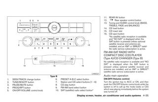
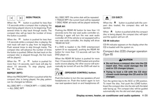
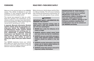
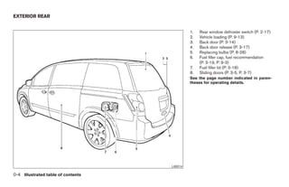
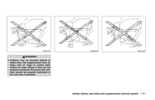
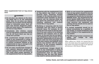
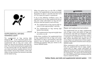
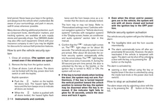
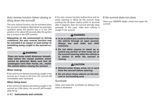
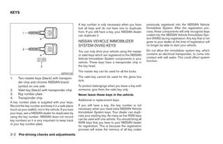
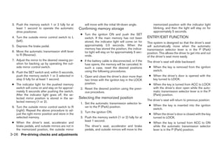
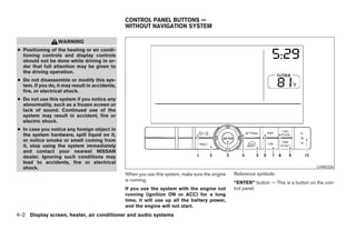
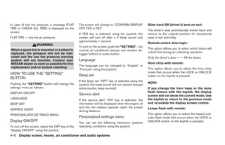
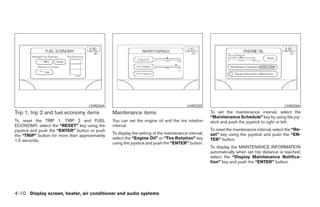
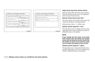
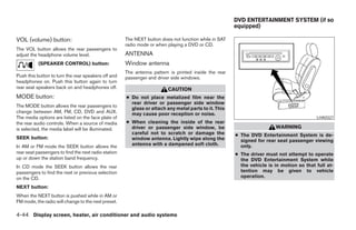
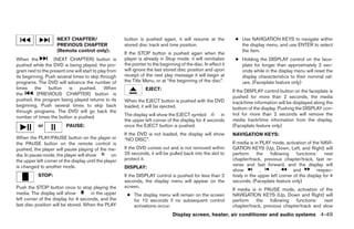
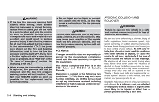
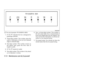
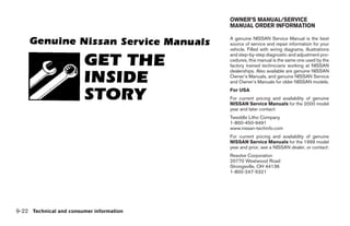
![REAR AV: reload (except 3.1 in [8 cm] diameter com-
pact discs).
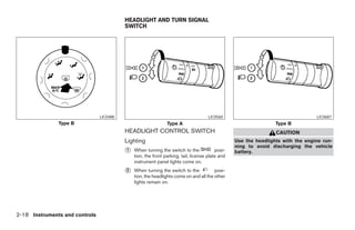
Pushing the REAR AV button for less than 1.5
seconds turns the rear seat audio controller on. All discs:
Pushing it again will turn the rear seat audio
● Press and hold the button for more
controller off. If the vehicle is not equipped with a
than 1.5 seconds. The compact discs will be
rear seat audio controller, the display will show
ejected one by one. If a disc is not removed
“REAR AV N/A”.
within 15 seconds, or the button is
If a DVD is loaded in the DVD entertainment pressed again during the eject sequence,
system (if so equipped), pushing the REAR AV the entire disc eject sequence will be can-
button for more than 1.5 seconds will turn the celed.
DVD player on.
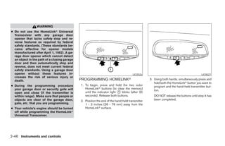
When this button is pushed while the compact
When the REAR AV button is pushed for more disc is being played, the compact disc will eject
than 1.5 seconds with a DVD loaded and another and the last source will be played.
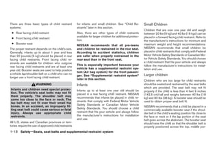
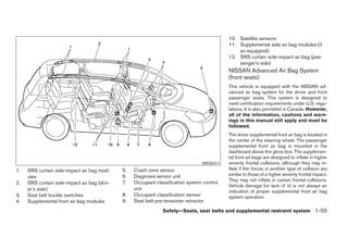
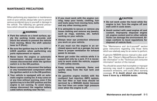
LHA0049
audio source playing, the other source will auto-
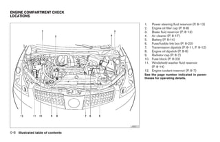
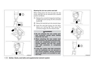
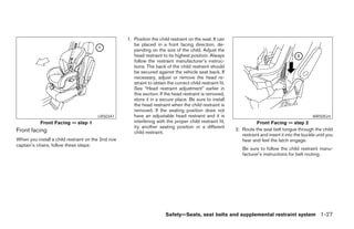
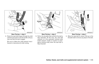
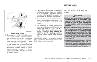
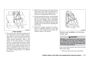
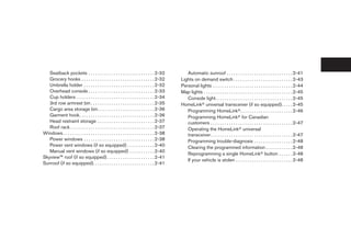
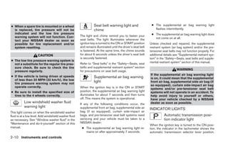
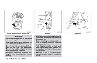
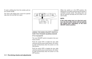
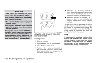
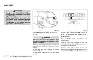
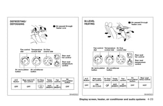
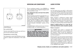
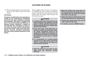
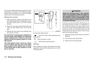
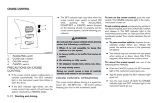
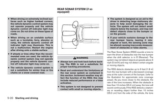
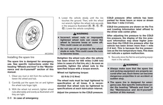
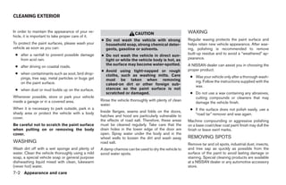
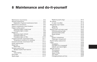
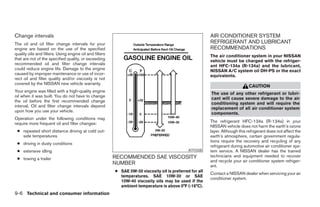
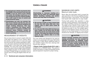
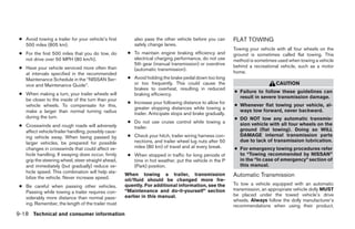
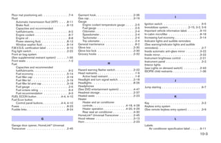
CD IN indicator:
matically be turned off and the DVD will start to CD CARE AND CLEANING
play. The slot numbers (1 - 6) will illuminate if CDs
have been loaded into the changer. ● Handle a CD by its edges. Do not bend the
(SPEAKER CONTROL) button: disc. Never touch the surface of the disc.
● Always place the discs in the storage case
Push this button to turn the rear speakers off and when they are not being used.
headphones on. Push this button again to turn
rear seat speakers back on and headphones off. ● To clean a disc, wipe the surface from the center
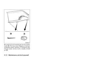
to the outer edge using a clean, soft cloth. Do
CD EJECT: not wipe the disc using a circular motion.
● Do not use a conventional record cleaner or
Current disc: alcohol intended for industrial use.
● Press the slot number (1 - 6) for the desired ● A new disc may be rough on the inner and
disc, then press the button. The com- outer edges. Remove the rough edges by
pact disc will be ejected. If the disc is not rubbing the inner and outer edges with the
removed within 15 seconds, the disc will side of a pen or pencil as illustrated.
Display screen, heater, air conditioner and audio systems 4-41
੬ REVIEW COPY—2005 Quest (van)
Owners Manual—USA_English (nna)
08/04/04—tbrooks ੭](https://image.slidesharecdn.com/2005-quest-120818112849-phpapp01/85/2005-QUEST-OWNER-S-MANUAL-200-320.jpg)
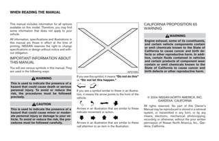
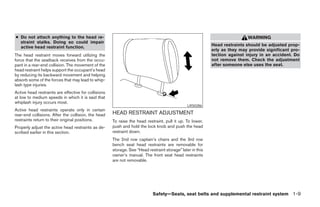
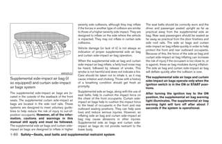
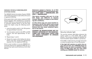
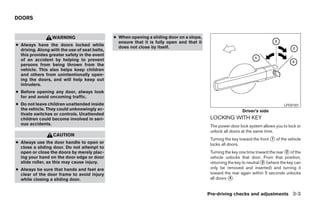
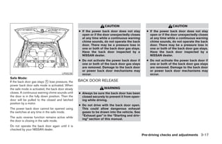
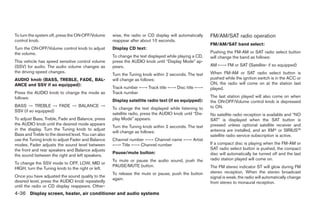
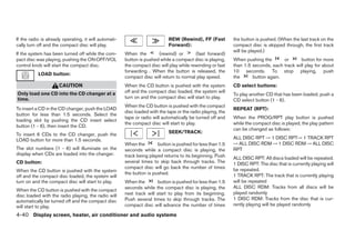
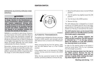
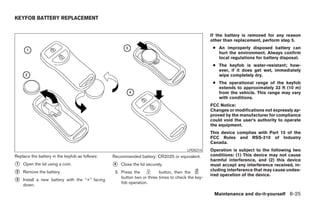
![CAUTION
● The glass screen on the liquid crystal
display may break if hit with a hard or
sharp object. If the glass breaks, do not
touch the liquid crystalline material,
which contains a small amount of mer-
cury. In case of contact with skin, wash
immediately with soap and water.
● Use a damp, soft cloth when cleaning
the DVD Entertainment System compo-
nents. Do not use solvents or cleaning
solutions.
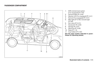
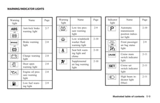
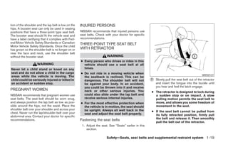
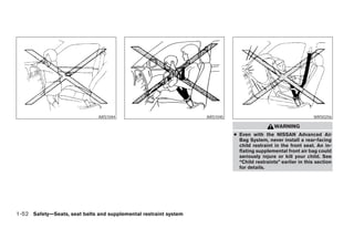
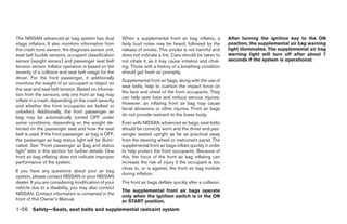
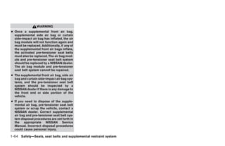
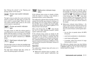
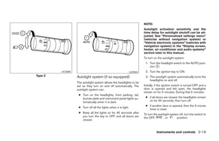
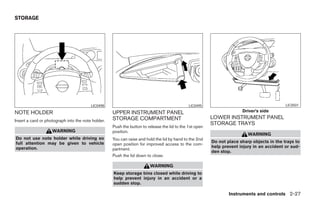
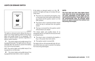
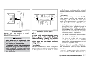
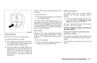
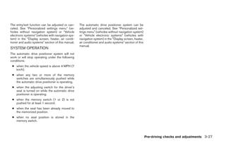
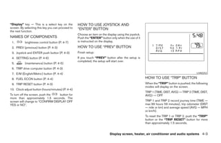
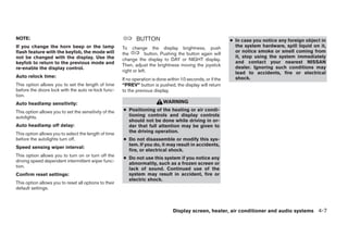
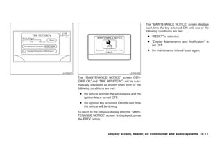
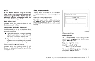
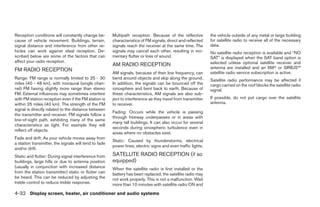
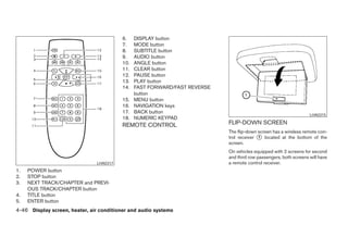
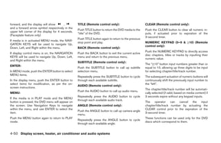
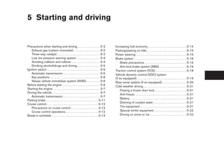
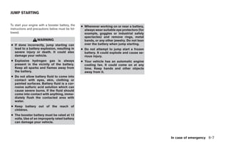
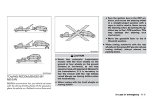
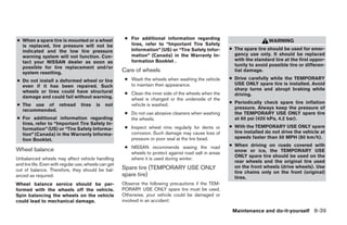
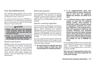
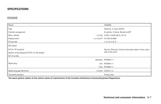
● Do not attempt to use the system in LHA0316
extreme temperature conditions [below
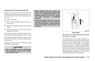
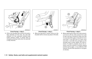
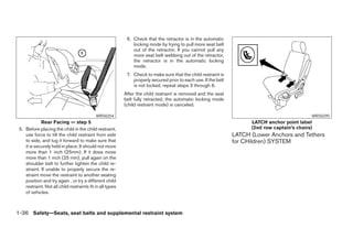
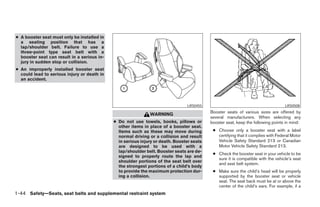
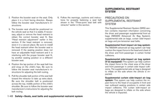
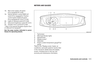
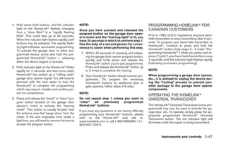
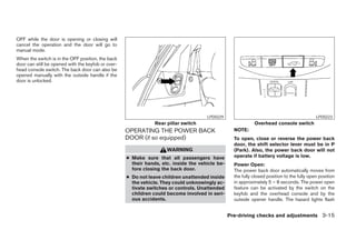
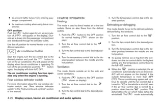
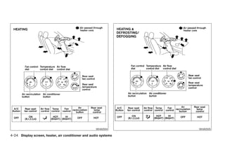
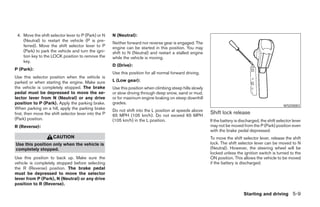
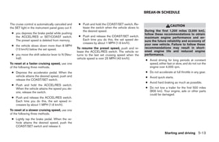
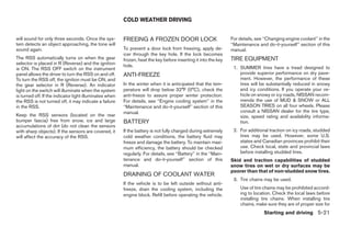
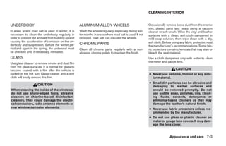
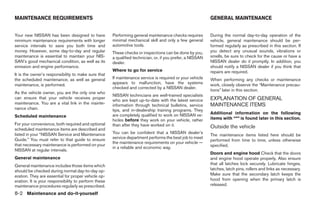
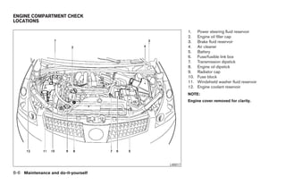
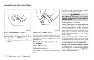
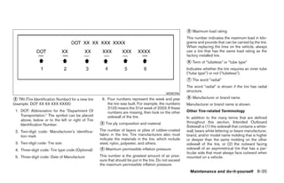
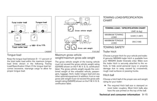
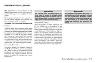
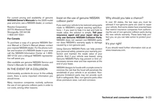
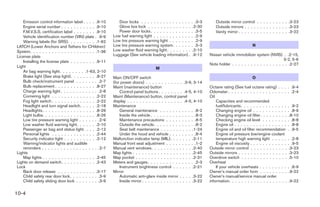
-4°F (-20°C) or above 158°F (70°C)]. 1. EJECT button DIGITAL VIDEO DISC (DVD) PLAYER
2. DVD slot CONTROLS
● To avoid draining the vehicle battery, do 3. ENTER button
not operate the system more than 15
minutes without starting the engine. 4. POWER on/off button
5. MODE button
6. Input jacks
7. STOP button
8. PLAY/PAUSE button
9. MENU button
10. DISPLAY button
11. NAVIGATION keys
Display screen, heater, air conditioner and audio systems 4-45
੬ REVIEW COPY—2005 Quest (van)
Owners Manual—USA_English (nna)
07/21/04—debbie ੭](https://image.slidesharecdn.com/2005-quest-120818112849-phpapp01/85/2005-QUEST-OWNER-S-MANUAL-204-320.jpg)
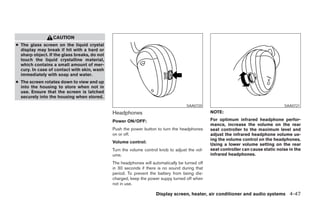
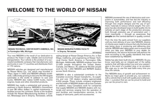
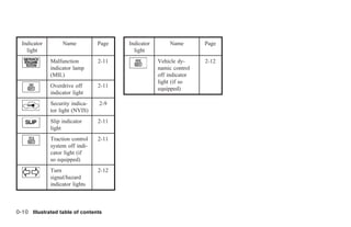
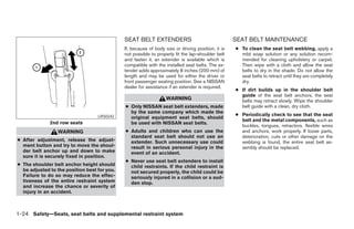
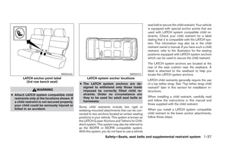
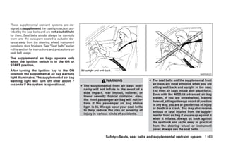
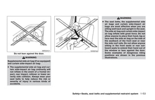
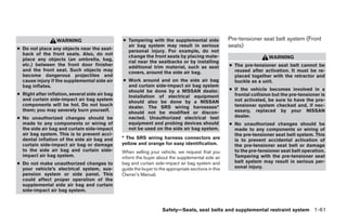
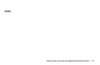
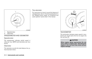
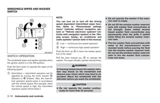
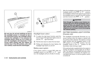
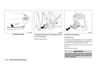
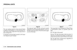
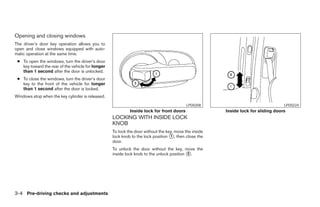
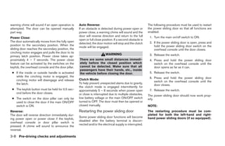
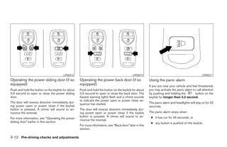
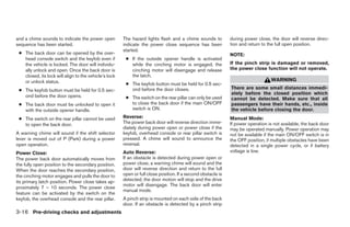
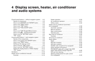
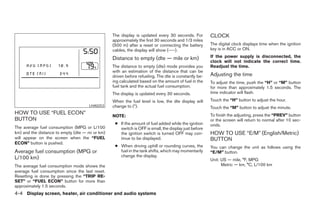
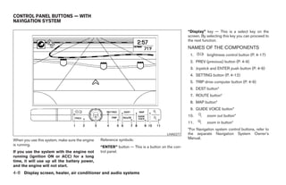
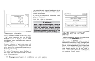
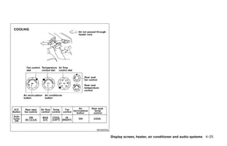
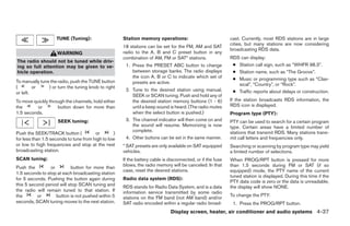
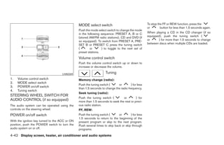
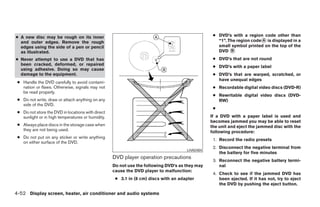
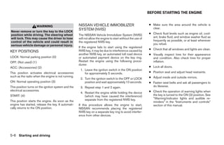
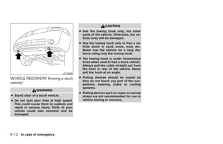
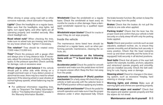
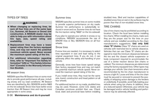
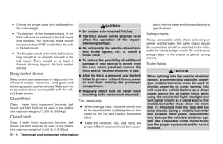
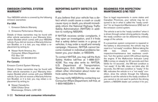
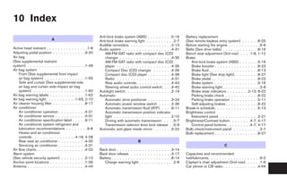
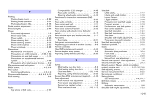
![Auxiliary input jacks ● Do not attempt to use the system in
The auxiliary input jacks are located on the control extreme temperature conditions [below
-4°F (-20°C) or above 158°F (70°C)].
panel. Compatible devices such as video games
camcorders and portable video players can be ● Do not attempt to operate the system in
connected to the auxiliary jacks. extreme humidity conditions (less than
10% or more than 75%).
The auxiliary jacks are color coded for identifica-
tion purposes.
● Yellow - video input
● White - left channel audio input
● Red - right channel audio input
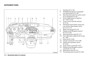
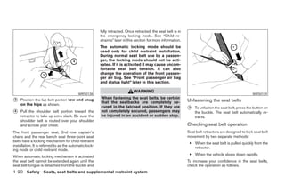
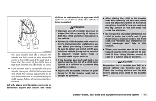
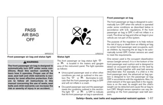
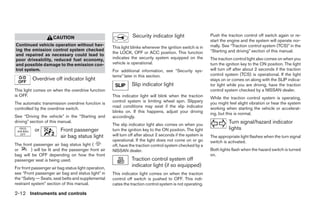
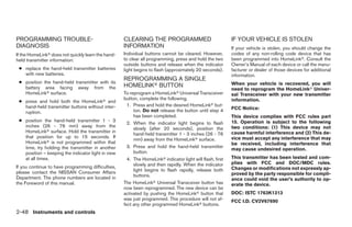
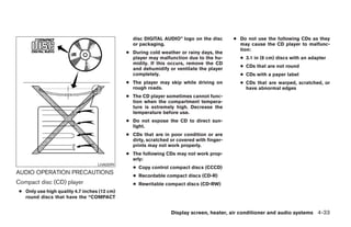
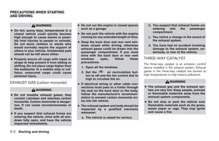
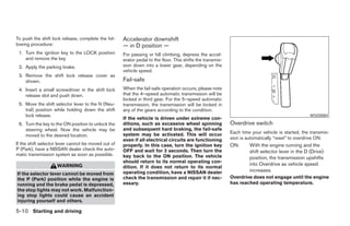
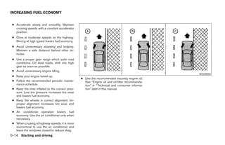
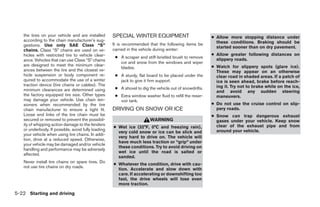
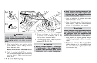
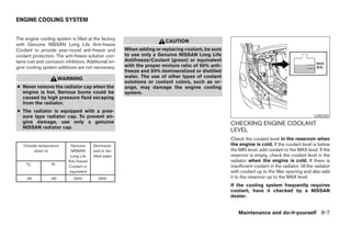
CARE AND MAINTENANCE LHA0049
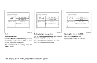
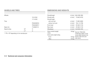
Use a lightly dampened, lint free cloth to clean the HOW TO HANDLE THE DVD
surfaces of your DVD Entertainment System.
(DVD player face, screen, remote control, etc.) CAUTION
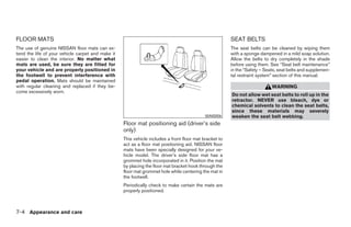
● Handle a DVD by its edges. Never touch
CAUTION the surface of the disc.
● Do not use any solvents or cleaning ● To clean a disc, wipe the surface from
solutions when cleaning the video the center to the outer edge using a
system. clean, soft cloth. Do not wipe the disc
● Do not use excessive force on the moni- using a circular motion.
tor screen. ● Do not use a conventional record
● Avoid touching or scratching the moni- cleaner, benzine, thinner or alcohol in-
tor screen as it may become dirty or tended for industrial use.
damaged.
Display screen, heater, air conditioner and audio systems 4-51
੬ REVIEW COPY—2005 Quest (van)
Owners Manual—USA_English (nna)
07/21/04—debbie ੭](https://image.slidesharecdn.com/2005-quest-120818112849-phpapp01/85/2005-QUEST-OWNER-S-MANUAL-210-320.jpg)

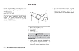


The document serves as an owner's manual for the Nissan Quest van, emphasizing the importance of reading the manual for safe vehicle operation and maintenance. It provides essential safety information, driving rules, and details about the quality and production of the vehicle, as well as Nissan's commitment to customer satisfaction and care. The manual also alerts users to governmental regulations regarding vehicle modifications and the potential hazards of certain vehicle components.