Download as PDF, PPTX


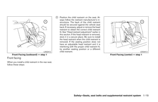


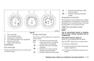
![LHA0271 LHA0272 LHA0273
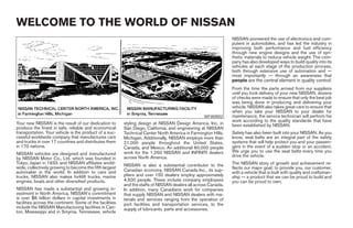
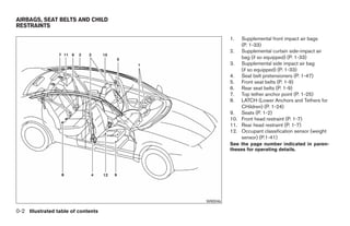
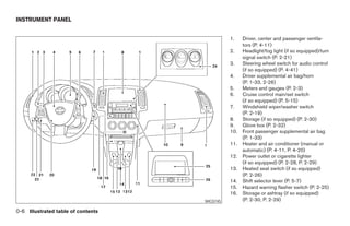
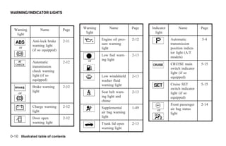
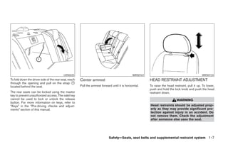
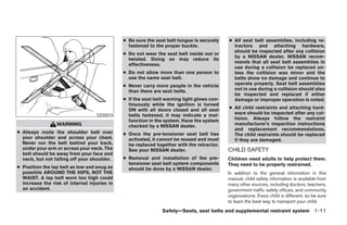
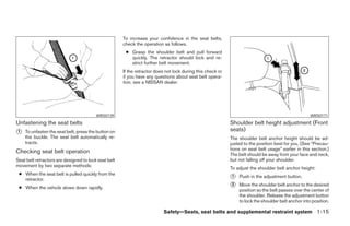
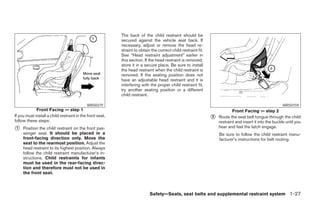
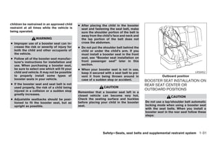
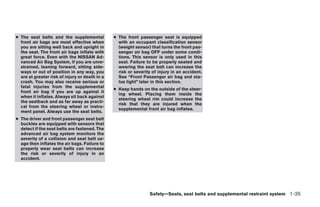
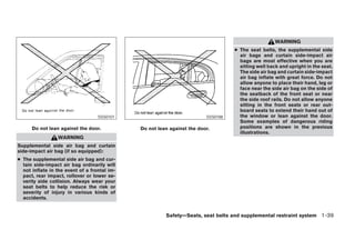
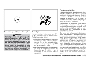
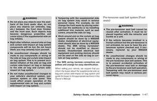
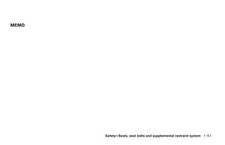
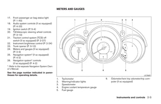
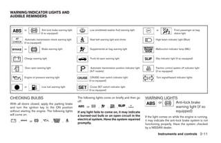
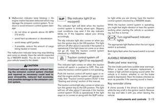
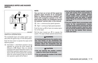
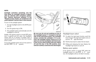
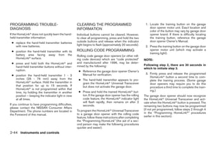
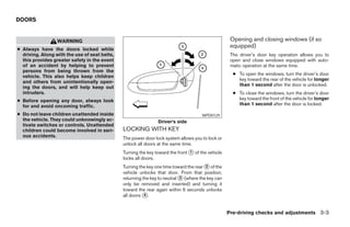
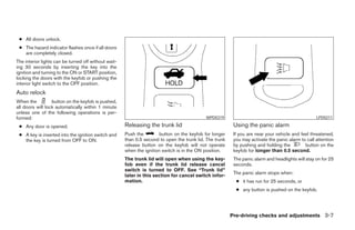
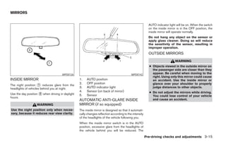
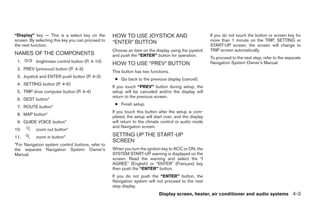
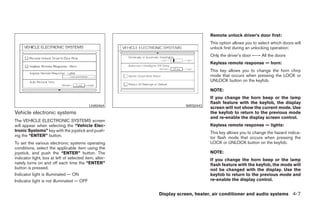
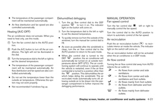
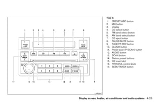
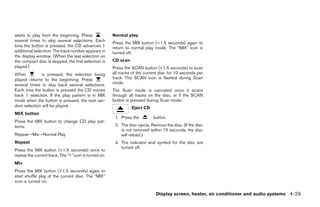
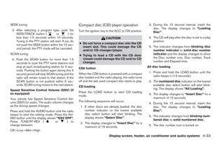
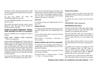
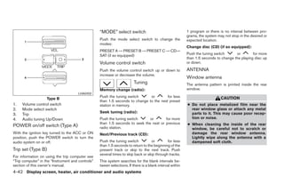
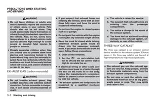
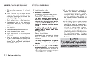
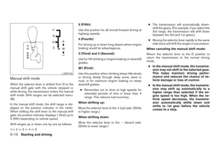
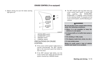
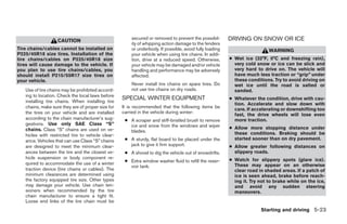
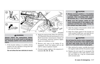
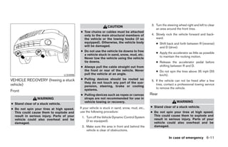
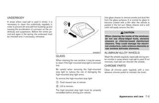
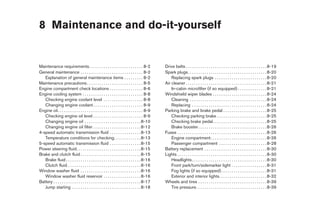
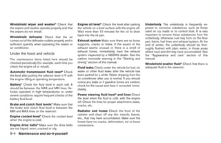
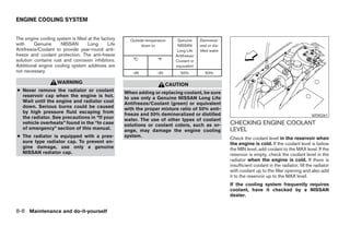
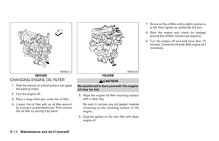
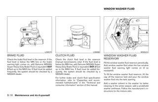
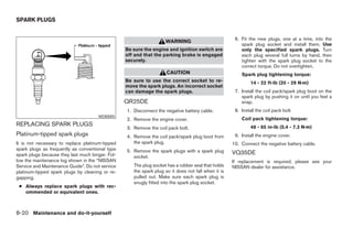
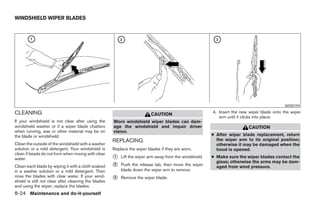
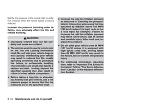
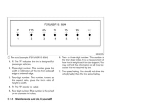
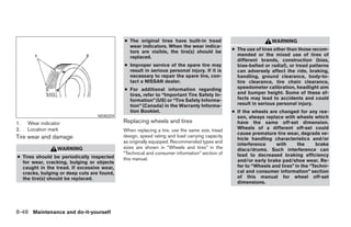
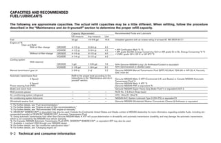
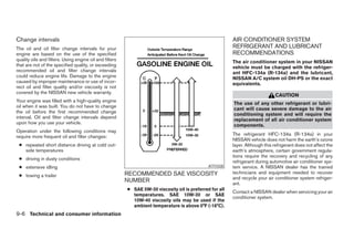
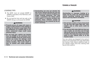
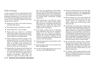
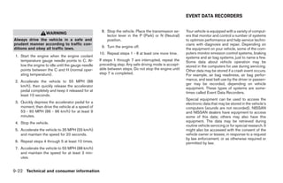
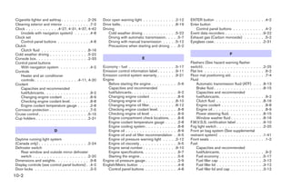
Setting daylight savings time: Adjusting the time to the GPS: Selecting the time zone:
Use the “Daylight Saving Time” key to adjust Select the “Auto Adjust” key. 1. Select the “Select Time Zone” key.
the clock to daylight savings time.
The time will be reset to the GPS time. The [TIME ZONE] screen will appear.
ON: The displayed time advances by 1 hour.
OFF: The current time is displayed.
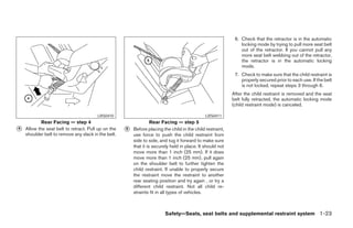
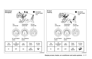
Display screen, heater, air conditioner and audio systems 4-9
੬ REVIEW COPY—2005 Altima (l30)
Owners Manual—USA_English (nna)
01/04/05—arosenma ੭](https://image.slidesharecdn.com/2005-altima-120818112814-phpapp01/85/2005-ALTIMA-OWNER-S-MANUAL-142-320.jpg)
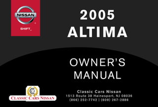
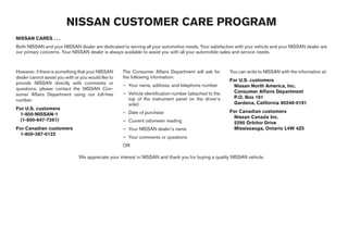
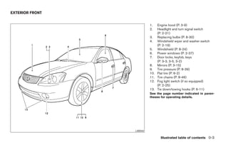
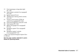
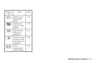
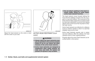
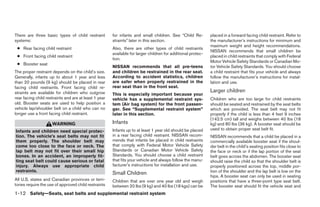
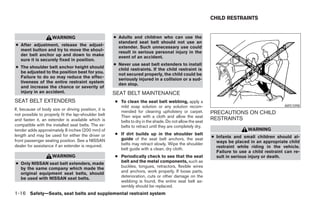
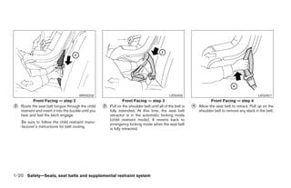
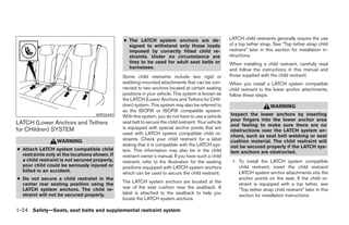
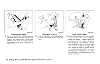
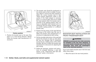
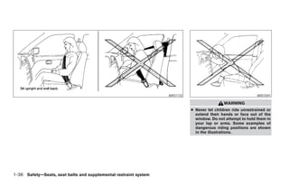
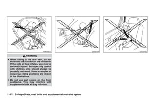
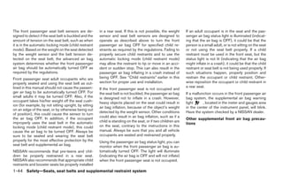
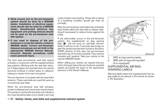
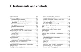
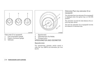
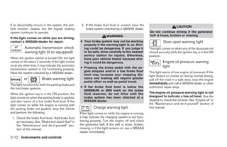
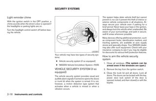
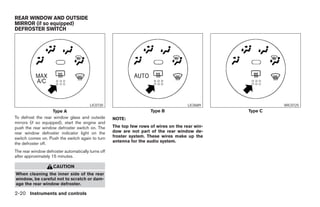
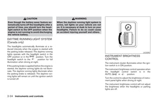
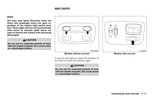
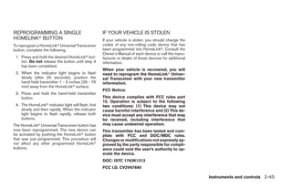
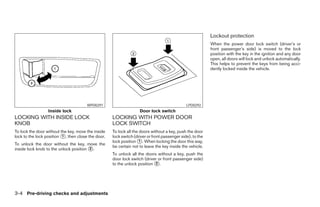
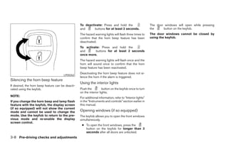
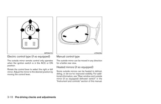
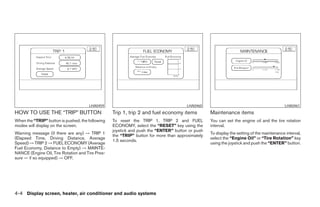
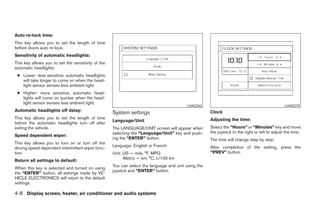
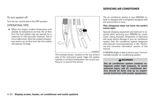
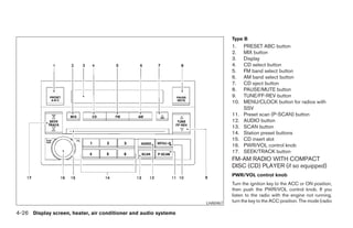
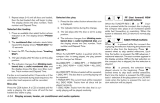
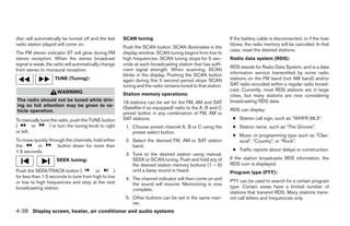
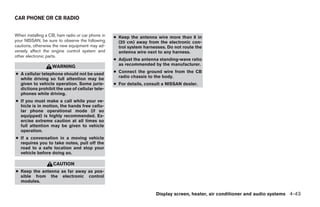
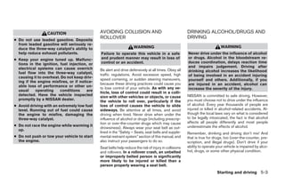
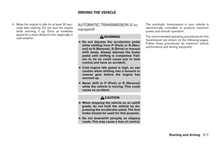
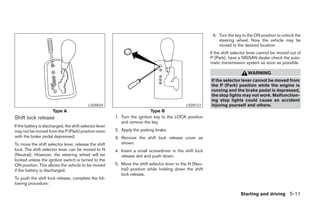
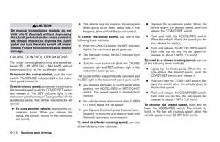
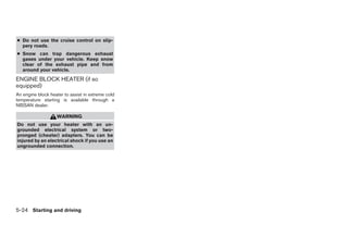
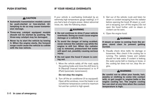
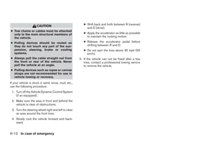
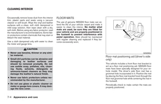
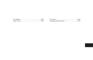
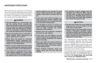
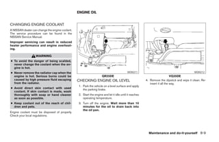
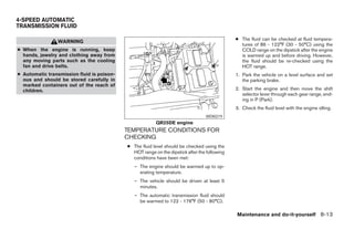
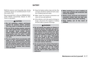
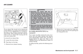
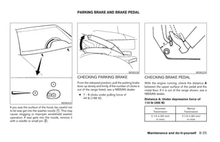
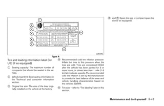
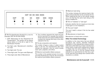
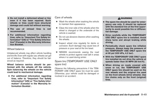
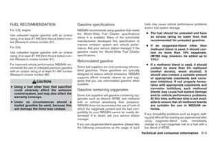
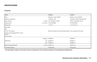
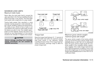
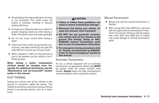
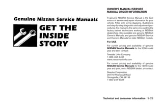
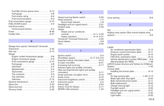
![The GPS time (manual time) corresponding to
the selected zone will be displayed. Pacific zone
has been set as the initial (default) setting.
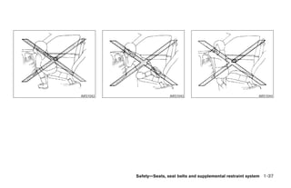
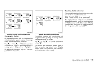
Beep setting
With this option ON, a beep will sound if any
audio button is pushed.
BUTTON
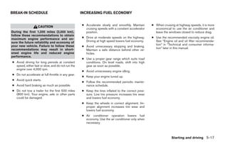
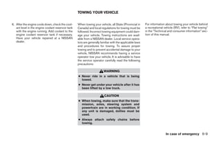
To change the display brightness, push
the button. Pushing the button again will
change the display to DAY or NIGHT display.
Then, adjust the brightness moving the joystick
right or left.
LHA0274
If no operation is done within 10 seconds, or if the
2. Select one of the following zones depending “PREV” button is pushed, the display will return
on the current location. to the previous display.
● Pacific zone
● Mountain zone
● Central zone
● Eastern zone
● Atlantic zone
● Newfoundland zone
After selection, the [CLOCK SETTINGS] screen
will appear.
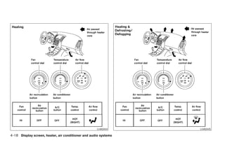
4-10 Display screen, heater, air conditioner and audio systems
੬ REVIEW COPY—2005 Altima (l30)
Owners Manual—USA_English (nna)
01/04/05—arosenma ੭](https://image.slidesharecdn.com/2005-altima-120818112814-phpapp01/85/2005-ALTIMA-OWNER-S-MANUAL-143-320.jpg)
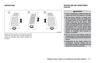
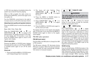
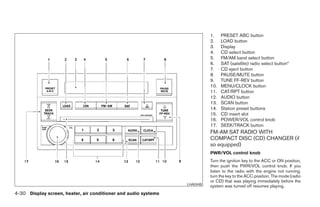
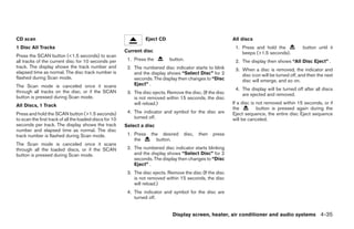
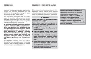
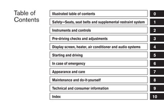
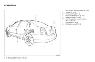
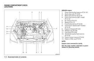
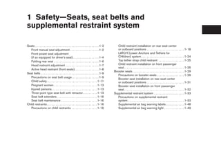
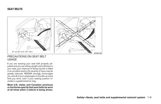
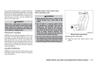
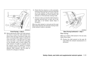
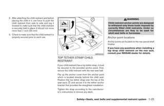
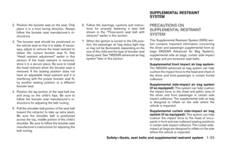
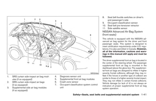
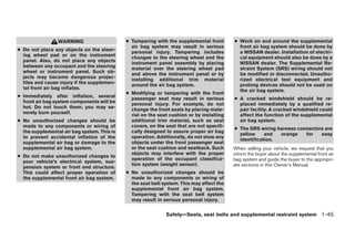
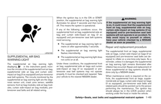
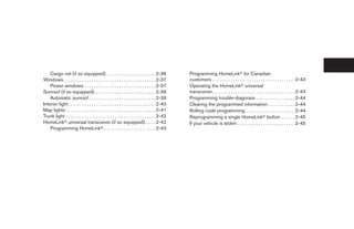
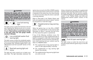
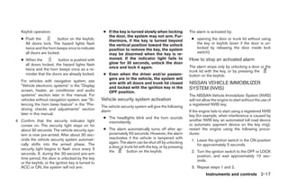
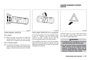
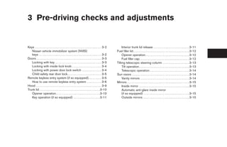
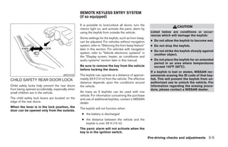
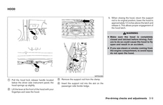
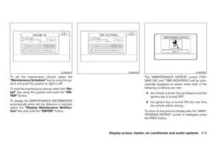
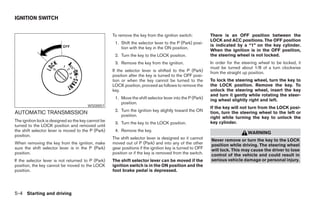
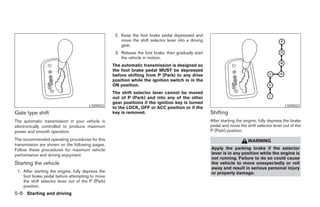
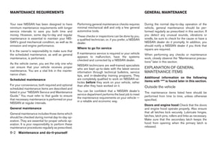
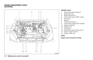
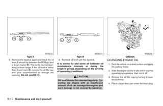
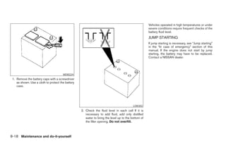
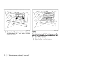
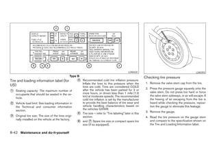
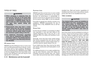
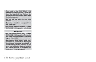
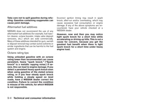
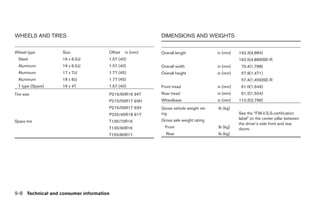
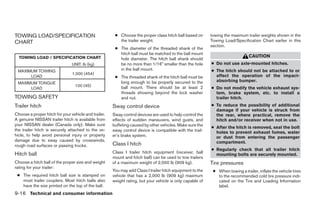
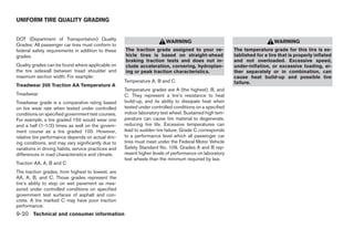
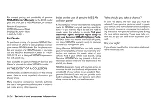
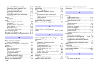
![REW (Rewind), FF (Fast the button is pushed. (When the last track on the CD EJECT:
Forward): compact disc is skipped through, the first track
will be played.) Current disc:
When the (rewind) or (fast forward)
button is pushed while a compact disc is playing, When pushing the or button for more ● Press the slot number (1 – 6) for the desired
the compact disc will play while rewinding or fast than 1.5 seconds, each track will play for about disc, then press the button. The com-
forwarding . When the button is released, the 10 seconds. To stop playing, push pact disc will be ejected. If the disc is not
compact disc will return to normal play speed. the button again. removed within 15 seconds, the disc will
reload (except 3.1 in [8 cm] diameter com-
When the CD button is pushed with the system CD select buttons: pact discs).
off and the compact disc loaded, the system will
To play another CD that has been loaded, push a All discs:
turn on and the compact disc will start to play.
CD select button (1 – 6).
● Press and hold the button for more
When the CD button is pushed with the compact than 1.5 seconds. The compact discs will be
CAT/RPT:
disc loaded with the tape or the radio playing, the ejected one by one. If a disc is not removed
tape or radio will automatically be turned off and When the CAT/RPT play button is pushed while within 15 seconds, or the button is
the compact disc will start to play. the compact disc is played, the play pattern can pressed again during the eject sequence,
be changed as follows: the entire disc eject sequence will be can-
SEEK/TRACK:
ALL DISC RPT → 1 DISC RPT→ 1 TRACK RPT celed.
When the button is pushed for less than 1.5 → ALL DISC RDM → 1 DISC RDM → ALL DISC When this button is pushed while the compact
seconds while a compact disc is playing, the RPT disc is being played, the compact disc will eject
track being played returns to its beginning. Push and the last source will be played.
several times to skip back through tracks. The ALL DISC RPT: All discs loaded will be repeated.
1 DISC RPT: The disc that is currently playing will CD IN indicator:
compact disc will go back the number of times
the button is pushed. be repeated. The slot numbers (1 – 6) will illuminate if CDs
1 TRACK RPT: The track that is currently playing have been loaded into the changer.
When the button is pushed for less than 1.5 will be repeated
seconds while the compact disc is playing, the ALL DISC RDM: Tracks from all discs will be
next track will start to play from its beginning. played randomly
Push several times to skip through tracks. The 1 DISC RDM: Tracks from the disc that is cur-
compact disc will advance the number of times rently playing will be played randomly
4-40 Display screen, heater, air conditioner and audio systems
੬ REVIEW COPY—2005 Altima (l30)
Owners Manual—USA_English (nna)
01/04/05—arosenma ੭](https://image.slidesharecdn.com/2005-altima-120818112814-phpapp01/85/2005-ALTIMA-OWNER-S-MANUAL-173-320.jpg)
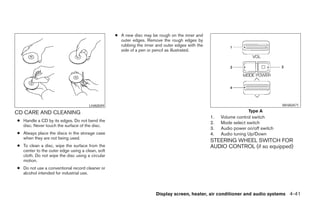
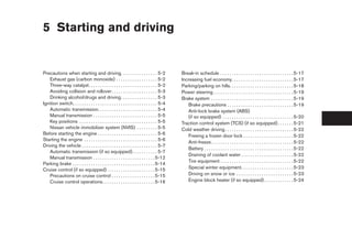
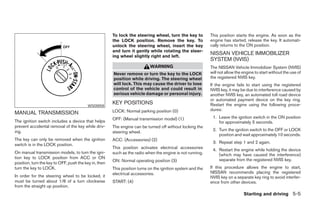
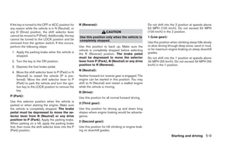
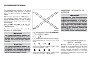
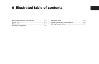
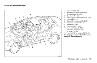
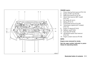
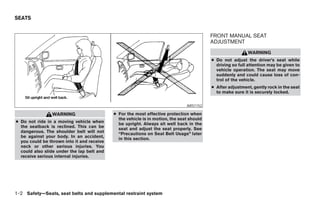
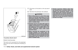
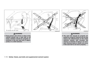
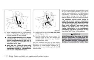
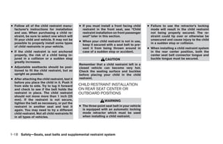
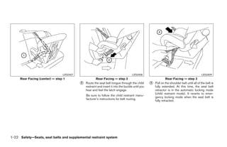
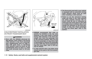
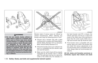
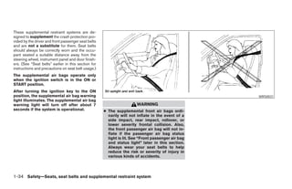
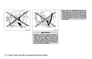
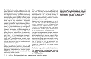
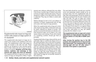
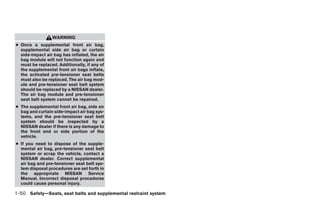
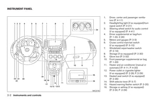
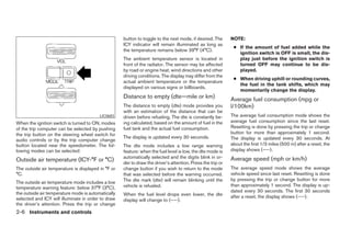
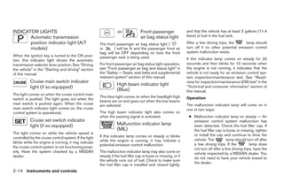
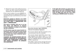
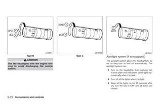
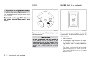
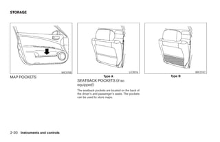
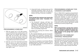
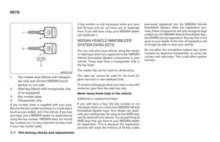
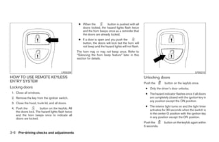
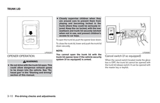
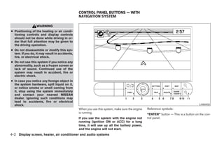
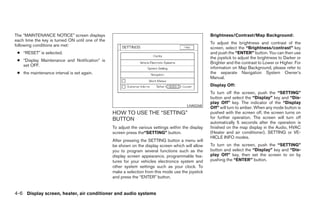
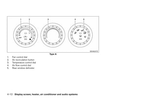
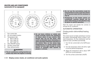
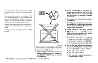
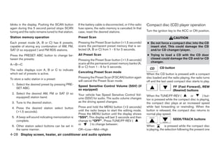
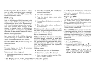
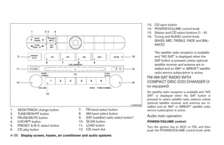
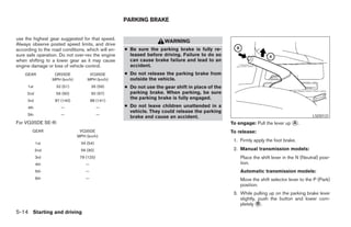
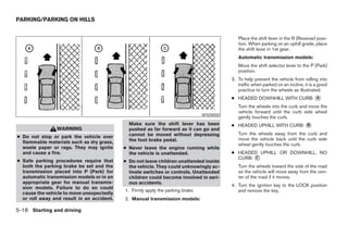
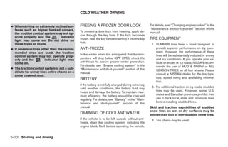
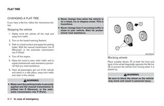
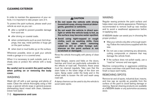
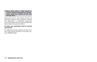
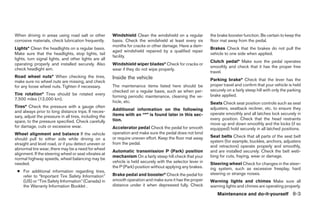
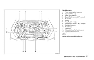
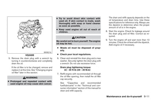
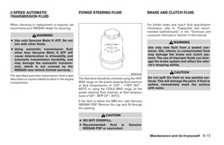
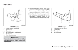
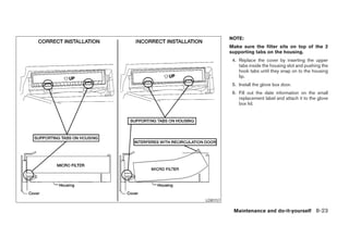
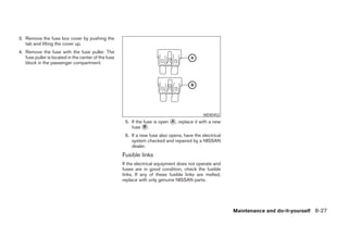
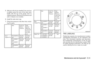
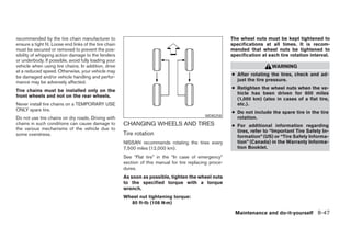
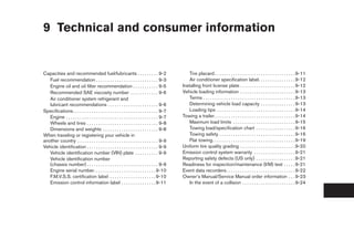
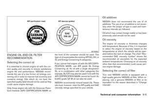
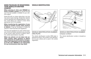
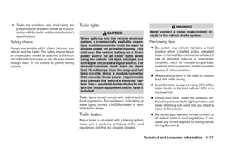
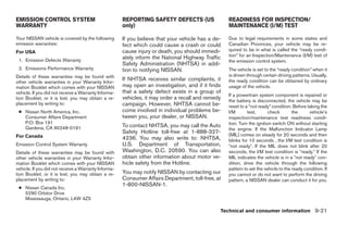
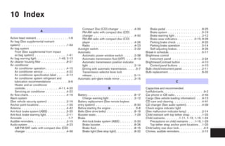
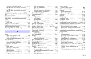
![Suggested upshift speeds For VQ35DE SE-R:
The following are suggested vehicle speeds for GEAR CHANGE ACCEL shift CRUISE shift
point MPH point MPH
shifting into a higher gear. These suggestions
(km/h) (km/h)
relate to fuel economy and vehicle performance.
Actual upshift speeds will vary according to road 1st to 2nd 13 (21) 13 (21)
conditions, the weather and individual driving 2nd to 3rd 23 (37) 16 (26)
habits. 3rd to 4th 33 (53) 27 (44)
For normal acceleration in low altitude areas (less 4th to 5th 39 (63) 36 (58)
than 4,000 ft [1219 m]): 5th to 6th
For QR25DE: For quick acceleration in low altitude areas and
GEAR CHANGE ACCEL shift CRUISE shift high altitude areas (over 4,000 ft [1219 m]):
LSD0133 point MPH point MPH Gear change MPH (km/h)
(km/h) (km/h)
6 - speed 1st to 2nd 15 (24)
1st to 2nd 15 (24) 15 (24)
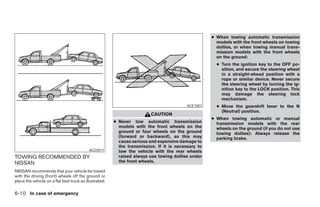
On the 6–speed manual transmission to back up, 2nd to 3rd 25 (40)
lift up on the collar just below the shift lever and 2nd to 3rd 25 (40) 18 (29)
3rd to 4th 40 (64)
then move it to the R (Reverse) position after 3rd to 4th 36 (58) 30 (48)
stopping the vehicle completely. 4th to 5th 45 (72)
4th to 5th 40 (64) 39 (62)
5th to 6th*
If it is difficult to move the shift lever into R For VQ35DE:
(Reverse) or 1 (1st), shift into N (Neutral), then *6 Speed available on SE-R models only.
release the clutch pedal. Depress the clutch GEAR CHANGE ACCEL shift CRUISE shift
pedal again and shift into R (Reverse) or 1 (1st). point MPH point MPH Suggested maximum speed in each
(km/h) (km/h) gear
1st to 2nd 13 (21) 13 (21)
Downshift to a lower gear if the engine is not
2nd to 3rd 23 (37) 16 (26) running smoothly, or if you need to accelerate.
3rd to 4th 33 (53) 27 (44)
Do not exceed the maximum suggested speed
4th to 5th 39 (63) 36 (58) (shown below) in any gear. For level road driving,
Starting and driving 5-13
੬ REVIEW COPY—2005 Altima (l30)
Owners Manual—USA_English (nna)
01/04/05—arosenma ੭](https://image.slidesharecdn.com/2005-altima-120818112814-phpapp01/85/2005-ALTIMA-OWNER-S-MANUAL-190-320.jpg)
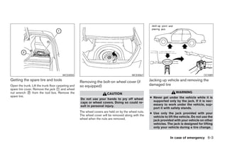

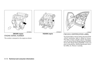


The document serves as a comprehensive owner's manual for the 2005 Nissan Altima, detailing important safety information and operational instructions for the vehicle. It emphasizes the necessity of understanding and adhering to the guidelines in the manual to ensure safe driving and proper vehicle maintenance. Additionally, it outlines the manufacturer's commitment to quality and customer care, while also cautioning against vehicle modifications that may void warranties.