Download as PDF, PPTX
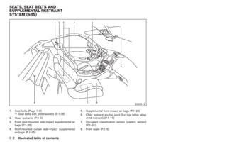
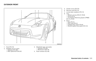
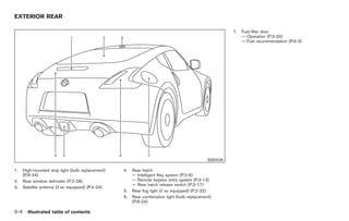
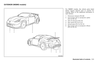


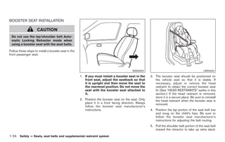

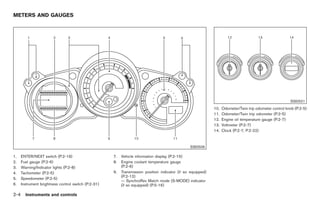


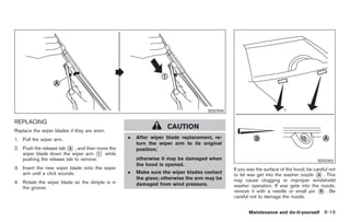
![Black plate (130,1)
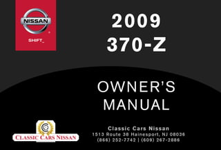
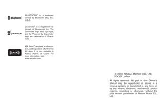
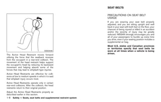
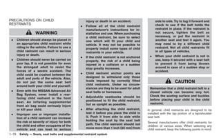
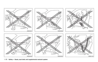
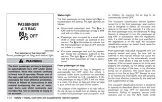
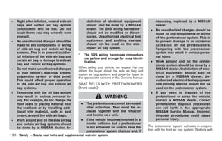
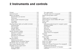
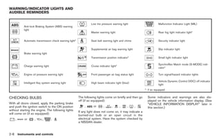
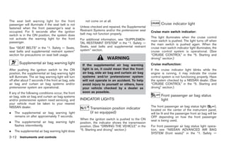
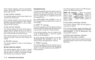
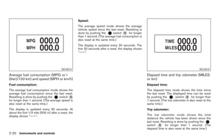
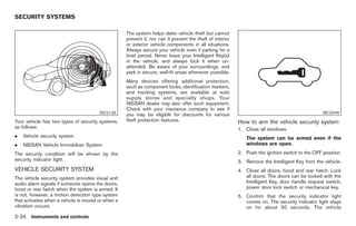
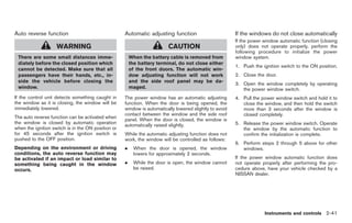
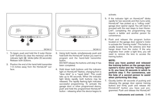
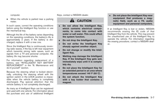
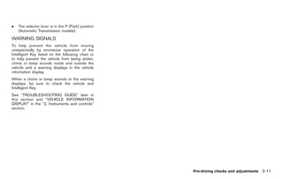
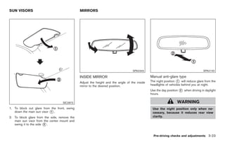
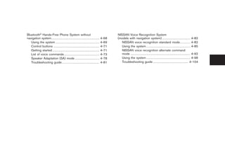
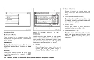
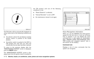
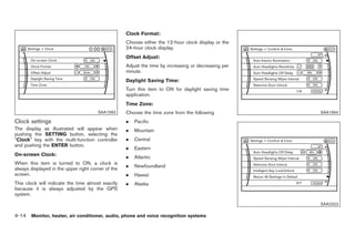
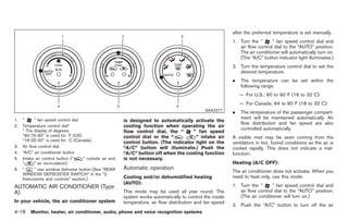
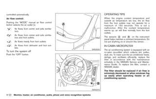
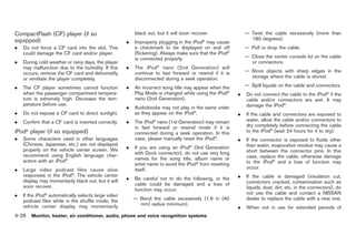
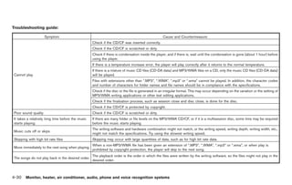
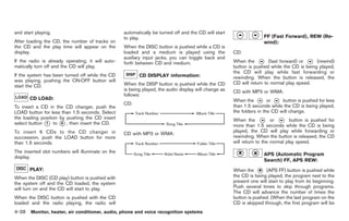
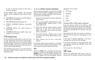
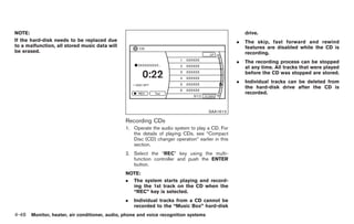
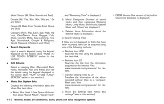
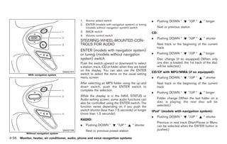
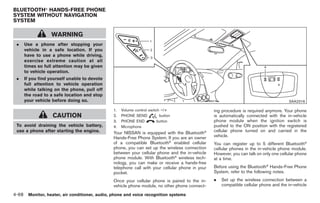
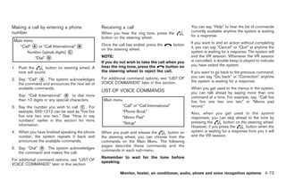
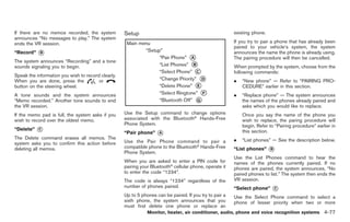
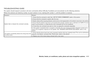
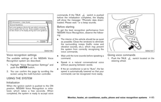
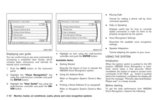
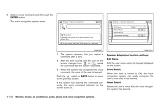
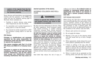
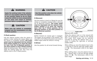
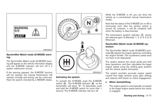
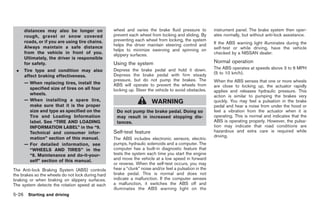
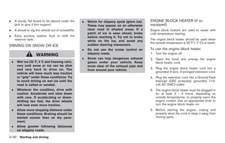
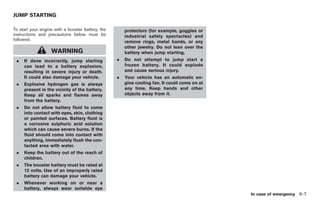
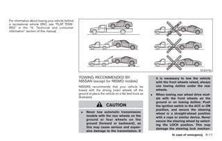
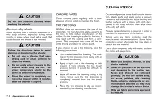
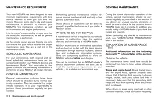
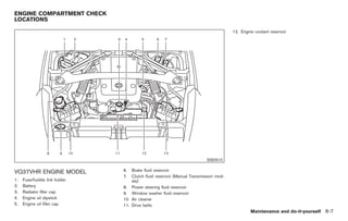
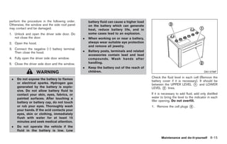
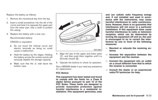
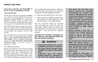
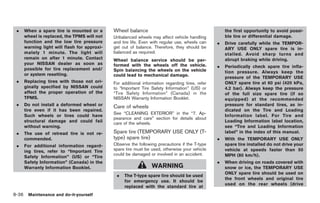
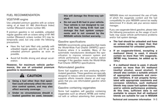
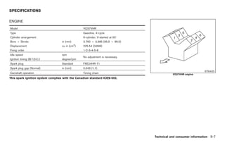
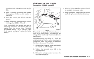
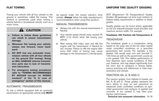
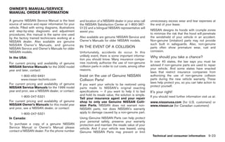
CENTER MULTI-FUNCTION
SAFETY NOTE CONTROL PANEL (models with
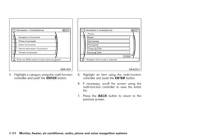
navigation system)
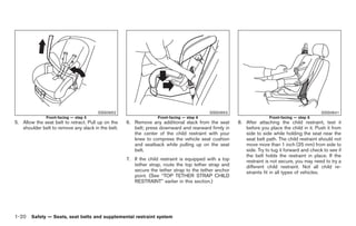
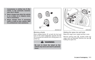
WARNING
. Do not disassemble or modify this
system. If you do, it may result in
accidents, fire, or electric shock.
. Do not use this system if you notice
any abnormality, such as a frozen
screen or lack of sound. Continued
use of the system may result in
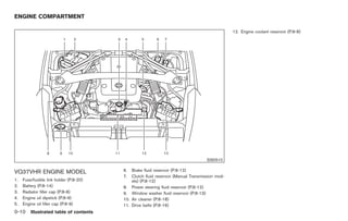
accident, fire or electric shock.
. In case you notice any foreign
object in the system hardware, spill
liquid on it, or notice smoke or smell SAA2273
coming from it, stop using the
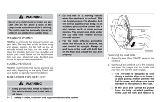
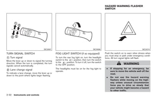
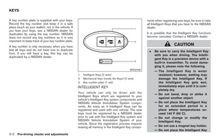
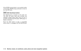
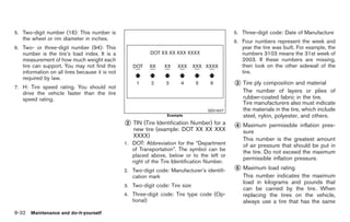
1. “STATUS” status display button (P.4-7)
system immediately and contact
2, 3, 7, 8, 9.
your nearest NISSAN dealer. Ignor-
For navigation system control buttons (Refer to the
ing such conditions may lead to separate Navigation System Owner’s Manual.)
accidents, fire, or electric shock. 4. Multi-function controller (P.4-3)
. Park the vehicle in a safe location 5. “PHONE” Bluetooth® Hands-Free Phone Sys-
and apply the parking brake to view tem button (P.4-58)
the images on the front center dis- 6. “ OFF” brightness control and display ON/
play screen using devices connected OFF button (P.4-7)
to the auxiliary input jacks. 10. “INFO” vehicle and navigation information button
(P.4-7)
Do not attempt to operate the system in 11. “SETTING” button (P.4-11)
extreme temperature conditions [below
−48F (−208C) and above 1588F (708C)].
Operating this system under these condi-
tions may result in system malfunctions.
4-2 Monitor, heater, air conditioner, audio, phone and voice recognition systems
Model "Z34-D" EDITED: 2009/ 3/ 30](https://image.slidesharecdn.com/2009-370-z-120818113244-phpapp02/85/2009-370-z-OWNER-S-MANUAL-137-320.jpg)
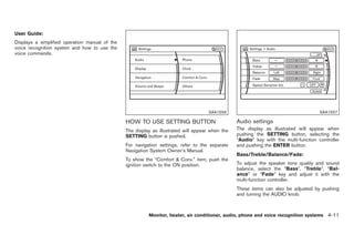

![Black plate (175,1)
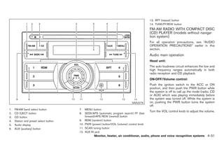
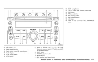
repeatedly to switch to the iPod® mode. . Genres
®
If the system has been turned off while the iPod . Composers
was playing, pushing the ON·OFF button will
start the iPod®. . Audiobooks
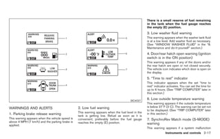
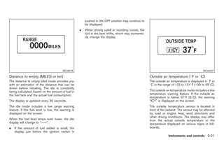
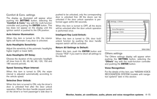
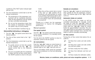
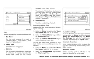
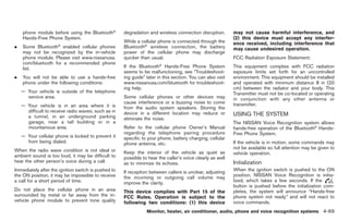
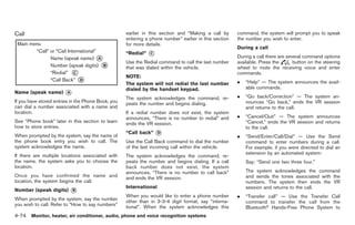
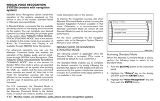
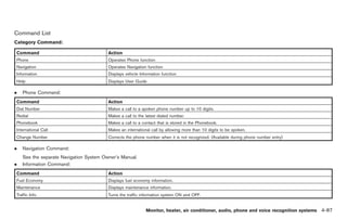
The following touch-panel buttons shown on the
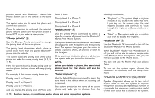
DISC·AUX button:
screen are also available:
When the DISC·AUX button is pushed with the
system off and the iPod® connected, the system . : returns to the previous screen.
will turn on. If another audio source is playing . : plays/pauses the music selected. MUSIC BOX HARD-DISK DRIVE (mod-
and the iPod® is connected, push the DISC·AUX
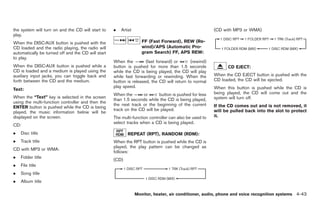
button repeatedly until the center display FF (Fast Forward), REW (Rewind)/APS els with navigation system)
changes to the iPod® mode. (Automatic Program Search) FF, APS REW: The “Music Box” hard-disk drive audio system
can store songs from CDs being played. The
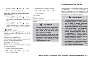
Interface: When the or button is pushed for
system has a 9.3 gigabyte (GB) storage
more than 1.5 seconds while the iPod® is
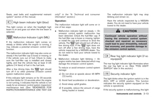
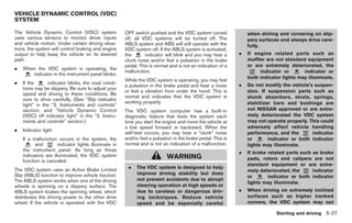
The interface for iPod® operation shown on the capacity and can record up to 200 hours
playing, the iPod® will play while fast forwarding
vehicle center display is similar to the iPod® (approximately 2,900 songs).
or rewinding. When the button is released, the
interface. Use the multi-function controller and iPod® will return to the normal play speed. The following CDs can be recorded in the
the ENTER or BACK button to play the iPod® “Music Box” hard-disk drive audio system.
with your favorite settings. When the or button is pushed for less
than 1.5 seconds while the iPod® is playing, the . CDs without MP3/WMA files
The following items can be chosen from the next track or the beginning of the current track
menu list screen. For further information about on the iPod® will be played. . Hybrid Compact Disc Digital Audio (Hybrid
each item, see the iPod® Owner’s Manual. CD-DA) specification in Super Audio CDs
The multi-function controller can also be used to
. Playlists select tracks when the iPod® is playing. . Compact Disc Digital Audio (CD-DA) spe-
cification in CD-Extras
. Artists
REPEAT (RPT), RANDOM (RDM): . First session of multisession disc
. Albums
When the RPT button is pushed while a track is Extreme temperature conditions [below
. Songs being played, the play pattern can be changed −48F (−208C) and above 1588F (708C)] could
. Podcasts as follows: affect the performance of the hard-disk.
Monitor, heater, air conditioner, audio, phone and voice recognition systems 4-47
Model "Z34-D" EDITED: 2009/ 3/ 30](https://image.slidesharecdn.com/2009-370-z-120818113244-phpapp02/85/2009-370-z-OWNER-S-MANUAL-182-320.jpg)

![Black plate (214,1)
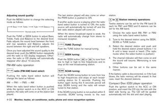
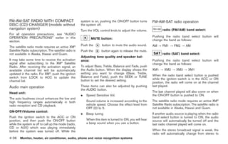
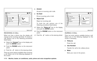
shown on the display and spoken through General rule
voice menu prompts. Commands other than
those that are displayed are not accepted. Only single digits 0 (zero) to 9 can be used. (For
Please follow the prompts given by the example, if you would like to say 500, “five zero
system. zero” can be used, but “five hundred” cannot.)
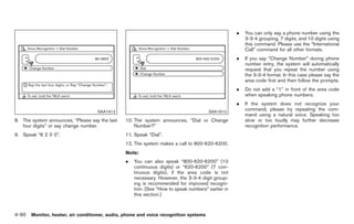
. If the command is not recognized, the Examples
system announces, “Please say again”. . 1-800-662-6200
Repeat the command in a clear voice.
— “One eight zero zero six six two six two
. Push the BACK button once to return to the zero zero”
previous screen.
Improving Recognition of Phone numbers
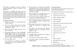
. If you want to cancel the command, push
and hold the TALK switch. The You can improve the recognition of phone
message, “Voice cancelled” will be an- numbers by saying the phone number in three
SAA1908
nounced. groups of numbers. For example, when you try to
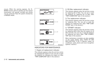
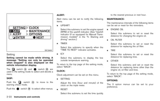
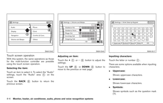
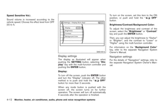
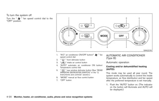
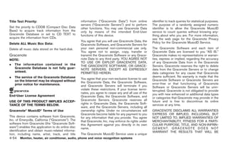
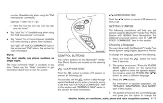
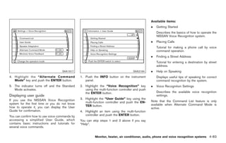
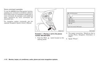
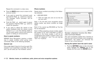
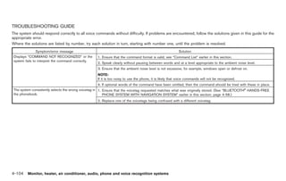
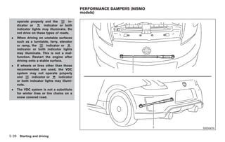
2. A list of commands appears on the screen, call 800-662-6200, say “eight zero zero” first,
and the system announces, “Would you like . Push the TALK switch to pause the and the system will then ask you for the next
to access Phone, Navigation, Information or operation. Push the TALK switch again three digits. Then, say “six six two”. After
Help?”. to restart the operation. recognition, the system will then ask for the last
. If you want to adjust the volume of the four digits. Say, “six two zero zero”. Using this
3. After the tone sounds and the icon on the method of phone digit entry can improve
screen changes from to , speak a system feedback, push the volume control
buttons [+] or [−] on the steering switch or recognition performance.
command.
use the audio system volume knob while the When speaking a house number, speak the
4. Continue to follow the voice menu prompts system is making an announcement. number “0” as “zero”. If the letter “o (Oh)” is
and speak after the tone sounds until your included in the house number, it will not be
desired operation is completed. How to speak numbers:
recognized as the number “0 (zero)” even if you
NISSAN Voice Recognition requires a certain speak “oh” instead of “zero”. You can only say
Operating tips:
way to speak numbers when giving voice “zero” for “0 (zero)”.
. Say a command after the tone. commands. Refer to the following examples.
. Commands that are available are always
4-86 Monitor, heater, air conditioner, audio, phone and voice recognition systems
Model "Z34-D" EDITED: 2009/ 3/ 30](https://image.slidesharecdn.com/2009-370-z-120818113244-phpapp02/85/2009-370-z-OWNER-S-MANUAL-221-320.jpg)

![Black plate (253,1)
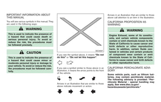
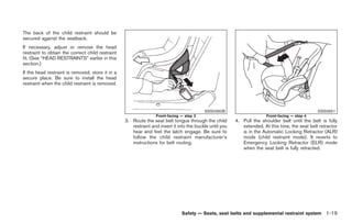
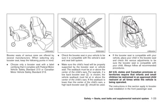
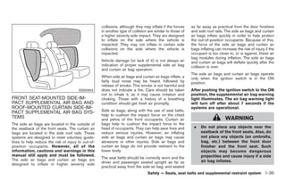
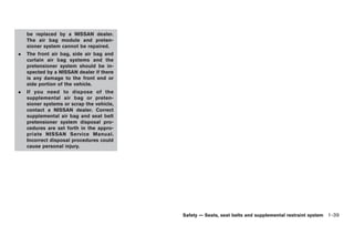
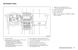
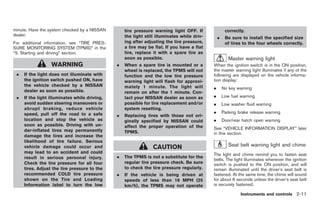
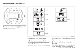
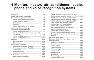
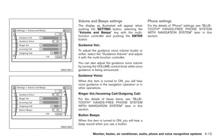
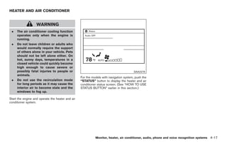
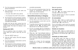
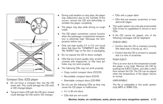
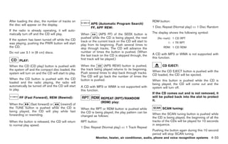
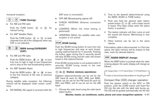
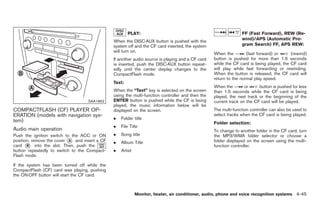
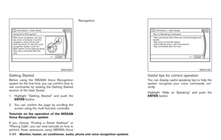
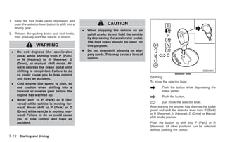
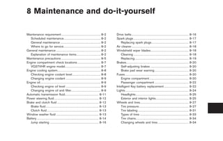
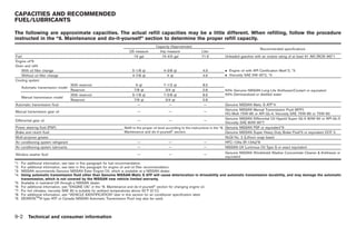
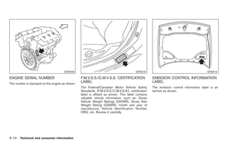
PARKING BRAKE
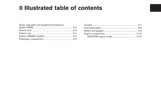
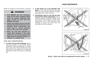
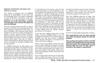
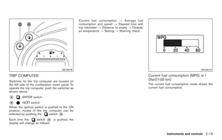
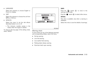
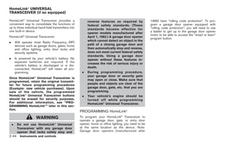
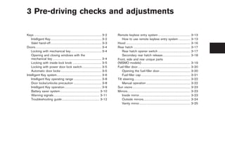
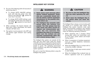
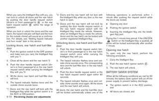
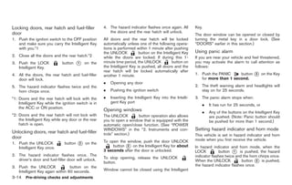
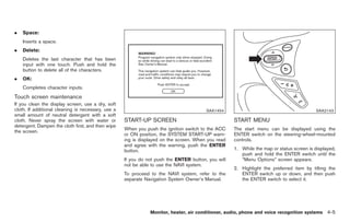
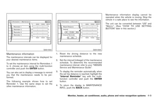
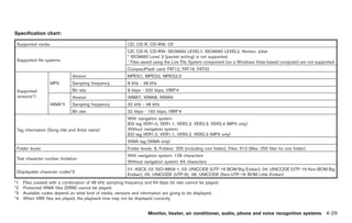
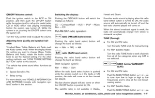
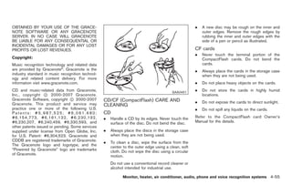
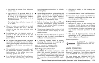
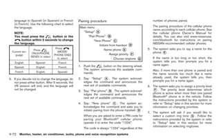
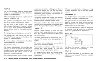
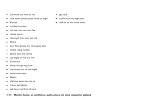
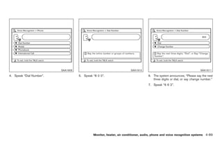
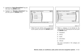
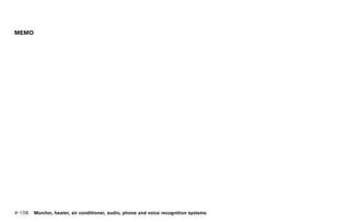
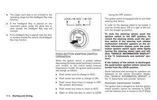
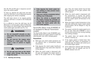
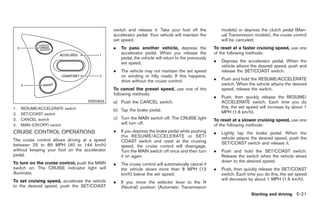
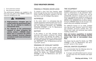
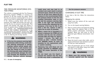
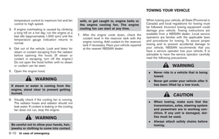
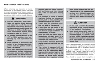
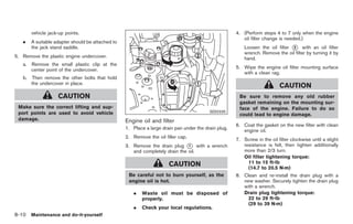
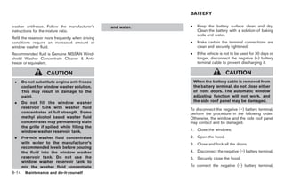
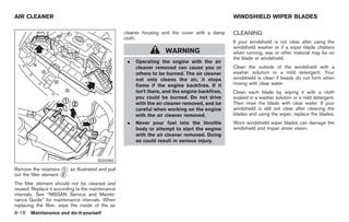
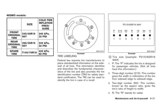
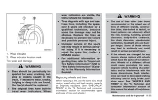
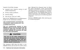
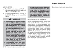
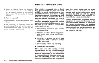
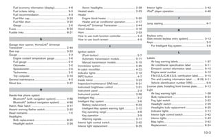
Suggested up-shift speeds Suggested maximum speed in each gear
Shown below are suggested vehicle speeds for Downshift to a lower gear if the engine is not WARNING
shifting into a higher gear. These suggestions running smoothly, or if you need to accelerate. . Be sure the parking brake is fully
relate to fuel economy and vehicle performance.
Do not exceed the maximum suggested speed released before driving. Failure to
Actual up-shift speeds will vary according to
road conditions, the weather and individual (shown below) in any gear. For level road do so can cause brake failure and
driving habits. driving, use the highest gear suggested for that lead to an accident.
speed. Always observe posted speed limits, and
. Do not release the parking brake
For normal acceleration in low altitude areas drive according to the road conditions, which
[less than 4,000 ft (1,219 m)]: will ensure safe operation. Do not over-rev the from outside the vehicle.
engine when shifting to a lower gear as it may . Do not use the gear shift in place of
Gear change MPH (km/h)
cause engine damage or loss of vehicle control. the parking brake. When parking, be
1st to 2nd 8 (13) sure the parking brake is fully
Gear MPH (km/h)
2nd to 3rd 16 (26) engaged.
1st 38 (62)
3rd to 4th 25 (40)
2nd 63 (102) . Do not leave children unattended in
4th to 5th 28 (45) a vehicle. They could release the
3rd 91 (146)
5th to 6th 33 (53) parking brake and cause an acci-
4th —
dent.
For quick acceleration in low altitude areas or in 5th —
high altitude areas [over 4,000 ft (1,219 m)]: 6th —
Gear change MPH (km/h)
1st to 2nd 15 (24)
2nd to 3rd 25 (40)
3rd to 4th 40 (64)
4th to 5th 45 (72)
5th to 6th 50 (80)
Starting and driving 5-19
Model "Z34-D" EDITED: 2009/ 3/ 30](https://image.slidesharecdn.com/2009-370-z-120818113244-phpapp02/85/2009-370-z-OWNER-S-MANUAL-260-320.jpg)


This document is the owner's manual for a Nissan vehicle, containing important safety, operation, and maintenance information. It advises against modifications that may affect performance or violate regulations and emphasizes safety practices such as using seat belts and avoiding distractions while driving. Additionally, it provides details about the Nissan customer care program and resources available for addressing vehicle concerns.