Downloaded 11 times


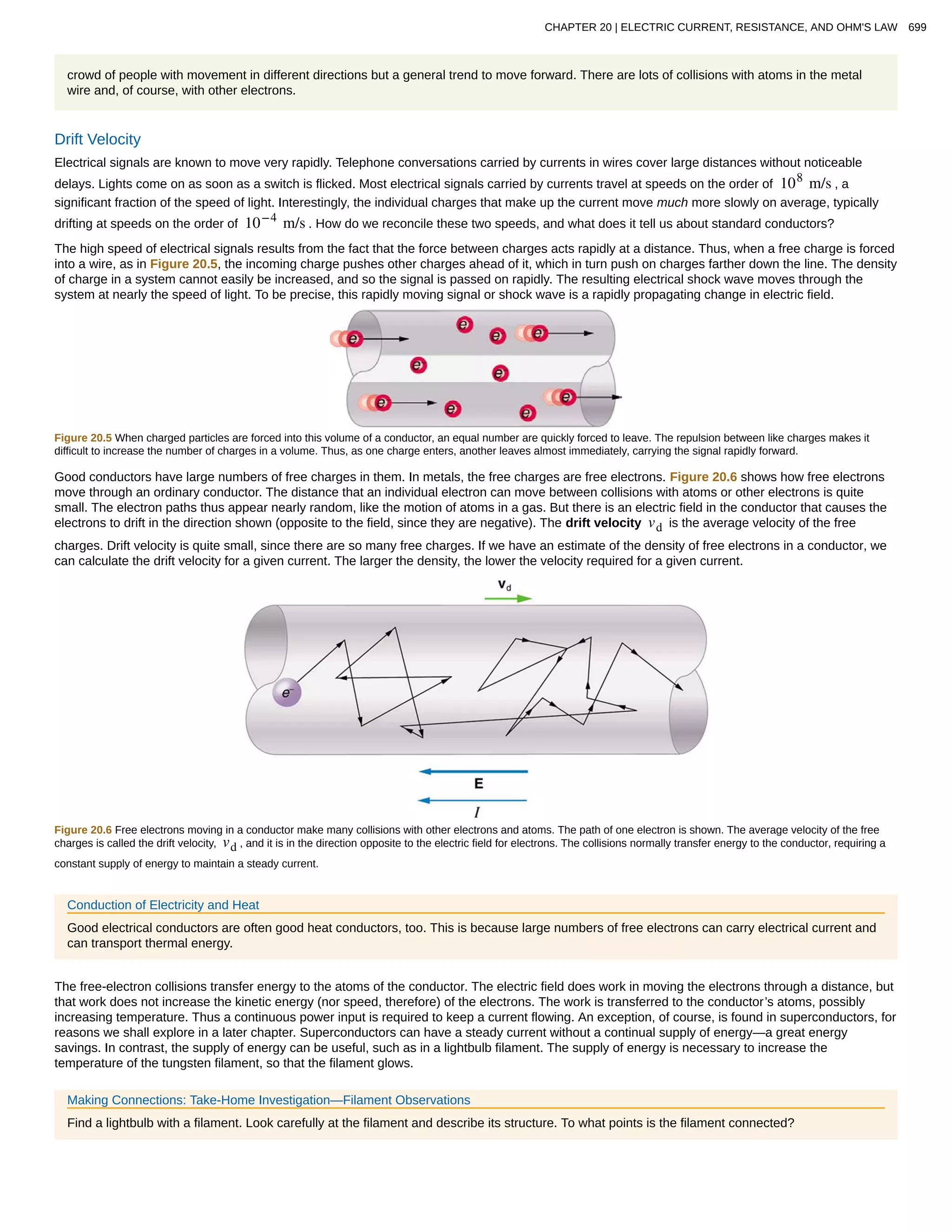


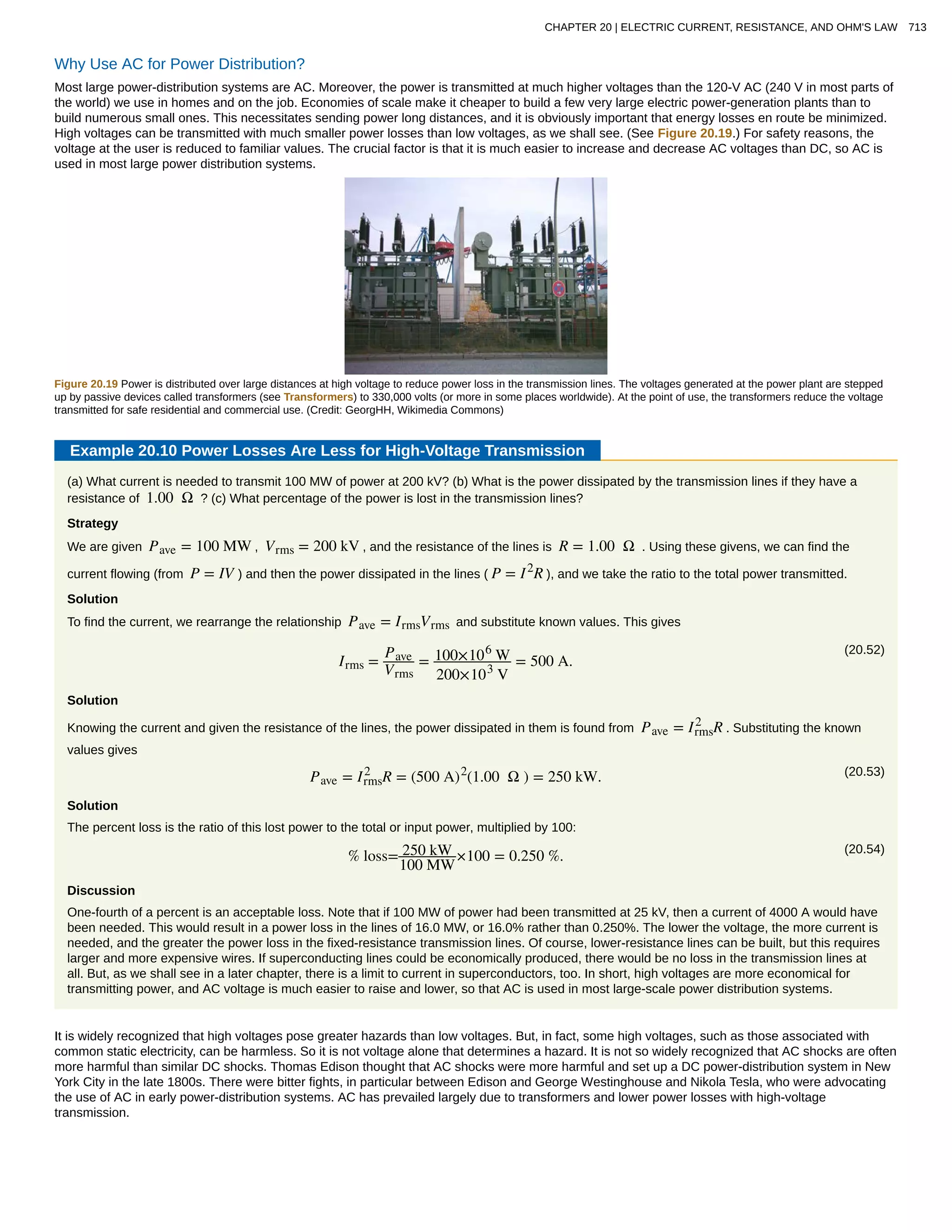
![Table 20.1 Resistivities ρ of Various materials at 20ºC
Material Resistivity ρ ( Ω ⋅ m )
Conductors
Silver 1.59×10⁻⁸
Copper 1.72×10⁻⁸
Gold 2.44×10⁻⁸
Aluminum 2.65×10⁻⁸
Tungsten 5.6×10⁻⁸
Iron 9.71×10⁻⁸
Platinum 10.6×10⁻⁸
Steel 20×10−8
Lead 22×10−8
Manganin (Cu, Mn, Ni alloy) 44×10−8
Constantan (Cu, Ni alloy) 49×10−8
Mercury 96×10−8
Nichrome (Ni, Fe, Cr alloy) 100×10−8
Semiconductors[1]
Carbon (pure) 3.5×10⁵
Carbon (3.5 − 60)×105
Germanium (pure) 600×10−3
Germanium (1 − 600)×10−3
Silicon (pure) 2300
Silicon 0.1–2300
Insulators
Amber 5×10¹⁴
Glass 109
− 1014
Lucite >1013
Mica 1011
− 1015
Quartz (fused) 75×1016
Rubber (hard) 1013
− 1016
Sulfur 1015
Teflon >1013
Wood 108
− 1011
1. Values depend strongly on amounts and types of impurities
704 CHAPTER 20 | ELECTRIC CURRENT, RESISTANCE, AND OHM'S LAW
This content is available for free at http://cnx.org/content/col11406/1.7](https://image.slidesharecdn.com/20electriccurrentresistanceohmslaw-160501120419/75/20-electric-current-resistance-ohms-law-10-2048.jpg)

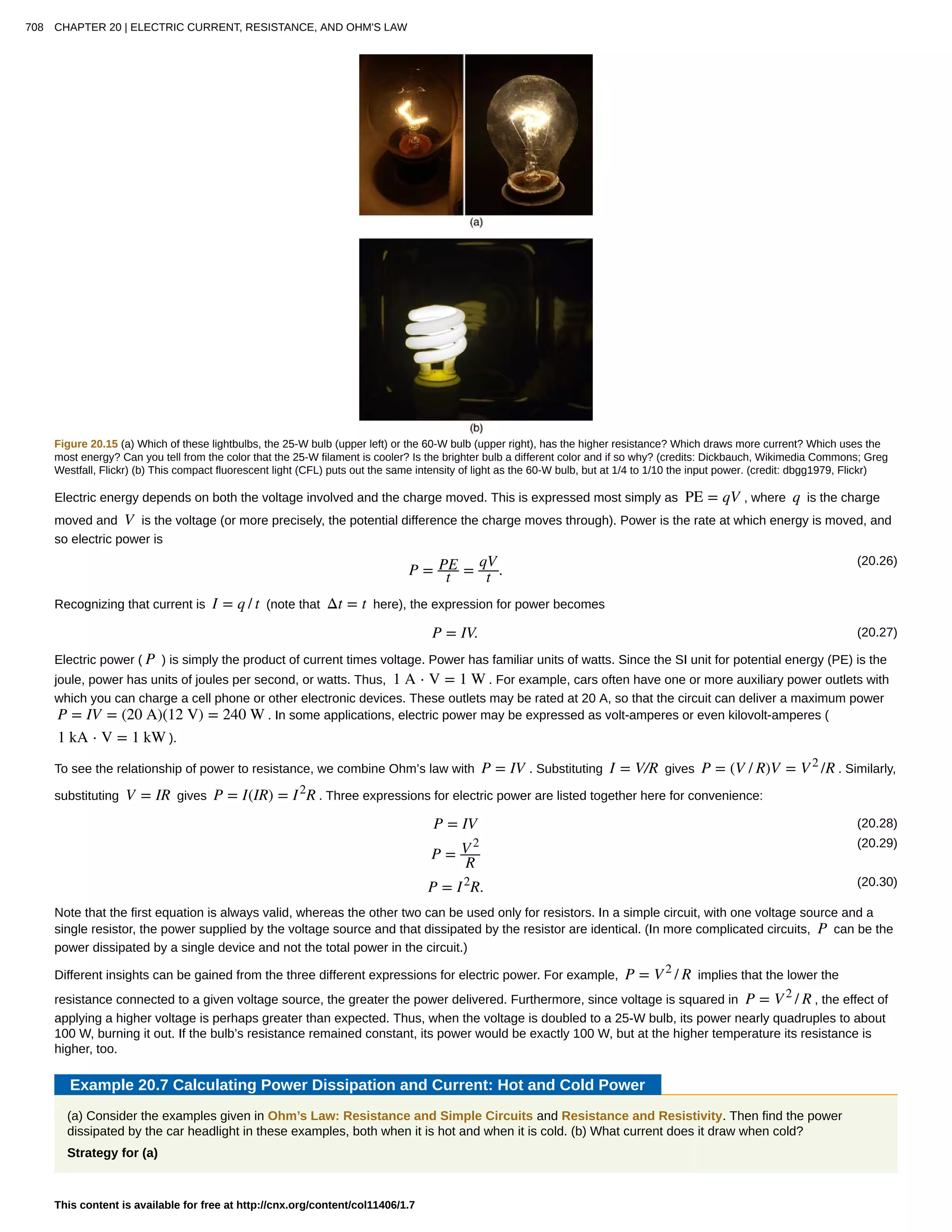
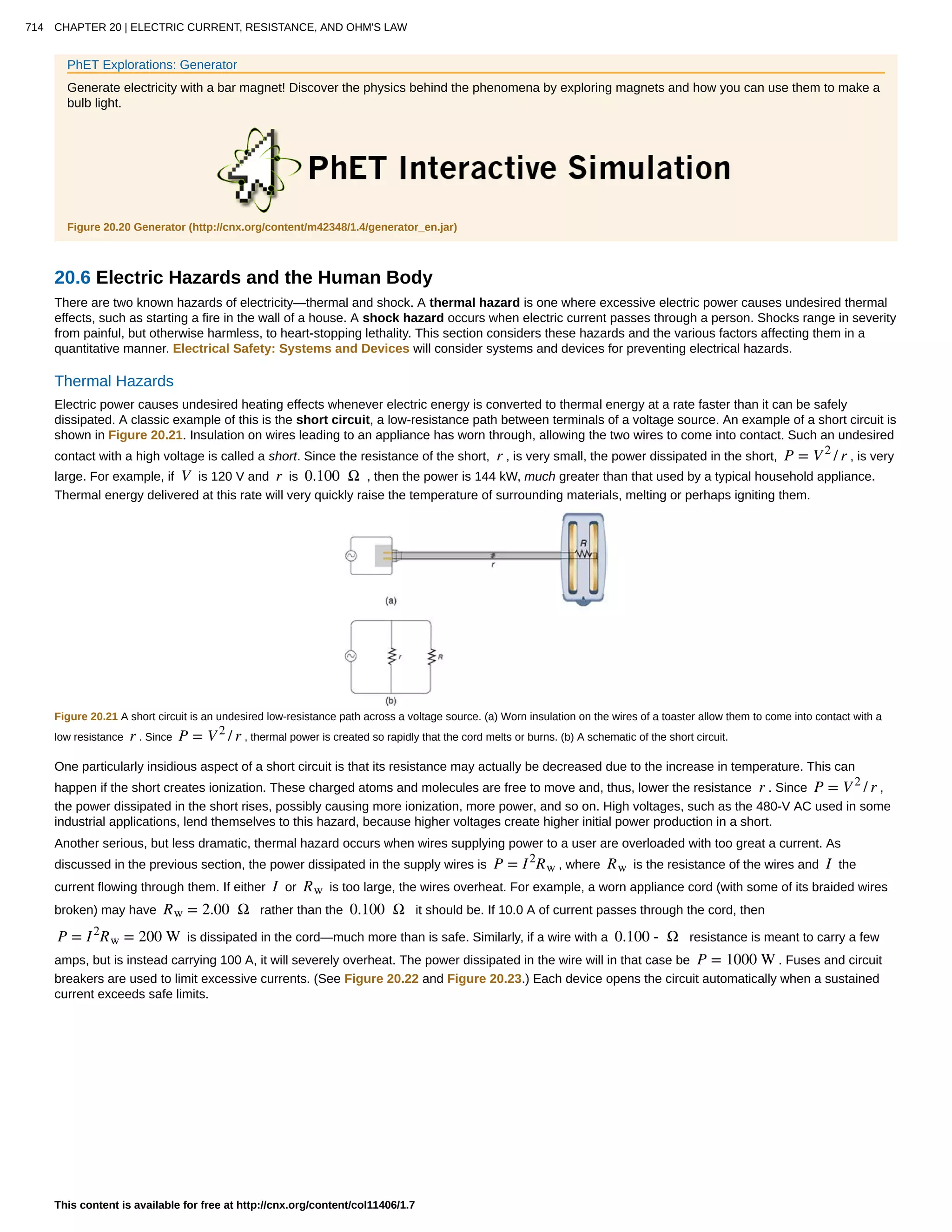
![Figure 20.12 The resistance of a sample of mercury is zero at very low temperatures—it is a superconductor up to about 4.2 K. Above that critical temperature, its resistance
makes a sudden jump and then increases nearly linearly with temperature.
Table 20.2 Tempature Coefficients of Resistivity α
Material Coefficient α (1/°C)[2]
Conductors
Silver 3.8×10⁻³
Copper 3.9×10⁻³
Gold 3.4×10⁻³
Aluminum 3.9×10⁻³
Tungsten 4.5×10⁻³
Iron 5.0×10⁻³
Platinum 3.93×10⁻³
Lead 3.9×10⁻³
Manganin (Cu, Mn, Ni alloy) 0.000×10⁻³
Constantan (Cu, Ni alloy) 0.002×10⁻³
Mercury 0.89×10⁻³
Nichrome (Ni, Fe, Cr alloy) 0.4×10⁻³
Semiconductors
Carbon (pure) −0.5×10⁻³
Germanium (pure) −50×10−3
Silicon (pure) −70×10−3
Note also that α is negative for the semiconductors listed in Table 20.2, meaning that their resistivity decreases with increasing temperature. They
become better conductors at higher temperature, because increased thermal agitation increases the number of free charges available to carry
current. This property of decreasing ρ with temperature is also related to the type and amount of impurities present in the semiconductors.
The resistance of an object also depends on temperature, since R0 is directly proportional to ρ . For a cylinder we know R = ρL / A , and so, if L
and A do not change greatly with temperature, R will have the same temperature dependence as ρ . (Examination of the coefficients of linear
expansion shows them to be about two orders of magnitude less than typical temperature coefficients of resistivity, and so the effect of temperature
on L and A is about two orders of magnitude less than on ρ .) Thus,
(20.24)R = R0(1 + αΔT)
2. Values at 20°C.
706 CHAPTER 20 | ELECTRIC CURRENT, RESISTANCE, AND OHM'S LAW
This content is available for free at http://cnx.org/content/col11406/1.7](https://image.slidesharecdn.com/20electriccurrentresistanceohmslaw-160501120419/75/20-electric-current-resistance-ohms-law-12-2048.jpg)
![is the temperature dependence of the resistance of an object, where R0 is the original resistance and R is the resistance after a temperature
change ΔT . Numerous thermometers are based on the effect of temperature on resistance. (See Figure 20.13.) One of the most common is the
thermistor, a semiconductor crystal with a strong temperature dependence, the resistance of which is measured to obtain its temperature. The device
is small, so that it quickly comes into thermal equilibrium with the part of a person it touches.
Figure 20.13 These familiar thermometers are based on the automated measurement of a thermistor’s temperature-dependent resistance. (credit: Biol, Wikimedia Commons)
Example 20.6 Calculating Resistance: Hot-Filament Resistance
Although caution must be used in applying ρ = ρ0(1 + αΔT) and R = R0(1 + αΔT) for temperature changes greater than 100ºC , for
tungsten the equations work reasonably well for very large temperature changes. What, then, is the resistance of the tungsten filament in the
previous example if its temperature is increased from room temperature ( 20ºC ) to a typical operating temperature of 2850ºC ?
Strategy
This is a straightforward application of R = R0(1 + αΔT) , since the original resistance of the filament was given to be R0 = 0.350 Ω , and
the temperature change is ΔT = 2830ºC .
Solution
The hot resistance R is obtained by entering known values into the above equation:
(20.25)R = R0(1 + αΔT)
= (0.350 Ω)[1 + (4.5×10⁻³
/ ºC)(2830ºC)]
= 4.8 Ω.
Discussion
This value is consistent with the headlight resistance example in Ohm’s Law: Resistance and Simple Circuits.
PhET Explorations: Resistance in a Wire
Learn about the physics of resistance in a wire. Change its resistivity, length, and area to see how they affect the wire's resistance. The sizes of
the symbols in the equation change along with the diagram of a wire.
Figure 20.14 Resistance in a Wire (http://cnx.org/content/m42346/1.5/resistance-in-a-wire_en.jar)
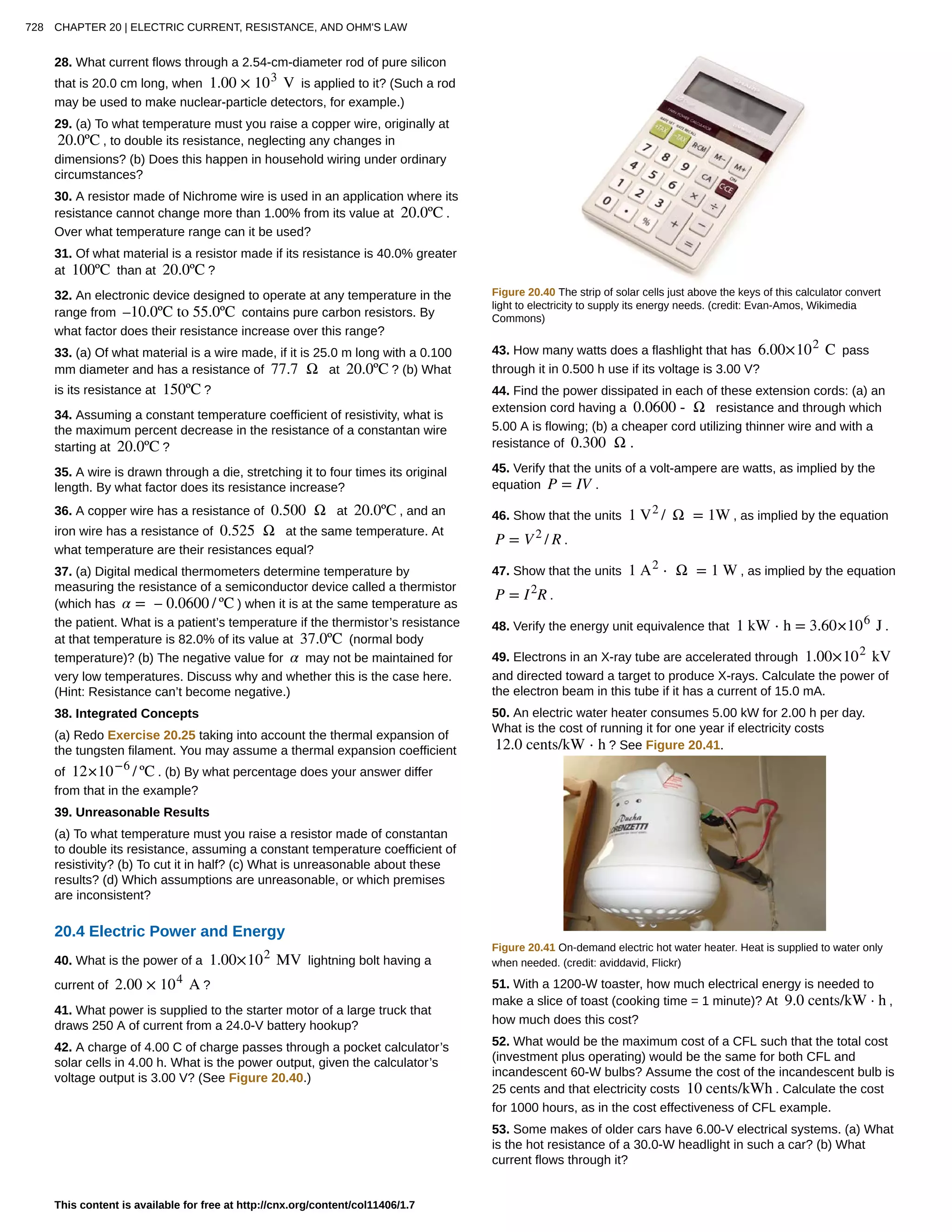
20.4 Electric Power and Energy
Power in Electric Circuits
Power is associated by many people with electricity. Knowing that power is the rate of energy use or energy conversion, what is the expression for
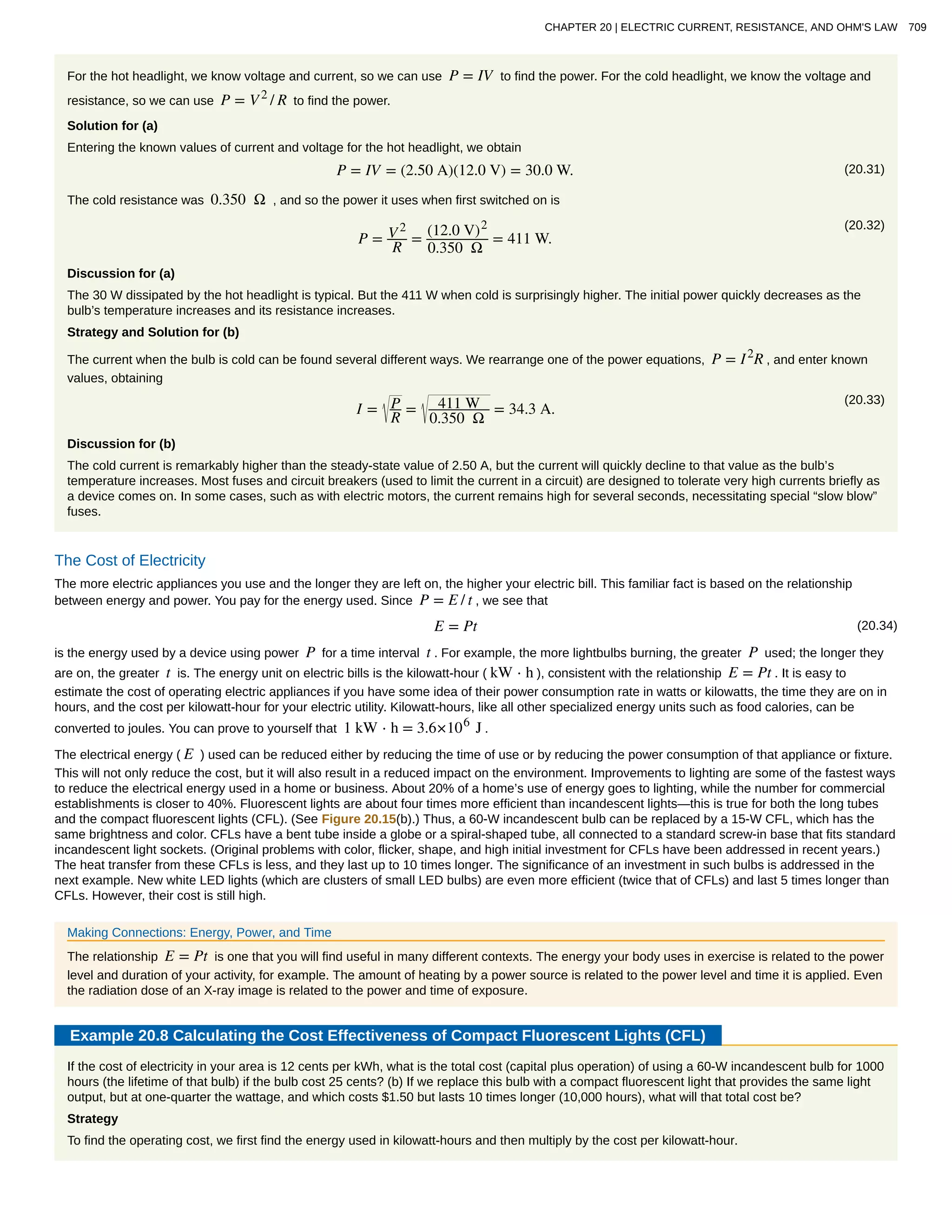
electric power? Power transmission lines might come to mind. We also think of lightbulbs in terms of their power ratings in watts. Let us compare a
25-W bulb with a 60-W bulb. (See Figure 20.15(a).) Since both operate on the same voltage, the 60-W bulb must draw more current to have a
greater power rating. Thus the 60-W bulb’s resistance must be lower than that of a 25-W bulb. If we increase voltage, we also increase power. For
example, when a 25-W bulb that is designed to operate on 120 V is connected to 240 V, it briefly glows very brightly and then burns out. Precisely
how are voltage, current, and resistance related to electric power?
CHAPTER 20 | ELECTRIC CURRENT, RESISTANCE, AND OHM'S LAW 707](https://image.slidesharecdn.com/20electriccurrentresistanceohmslaw-160501120419/75/20-electric-current-resistance-ohms-law-13-2048.jpg)

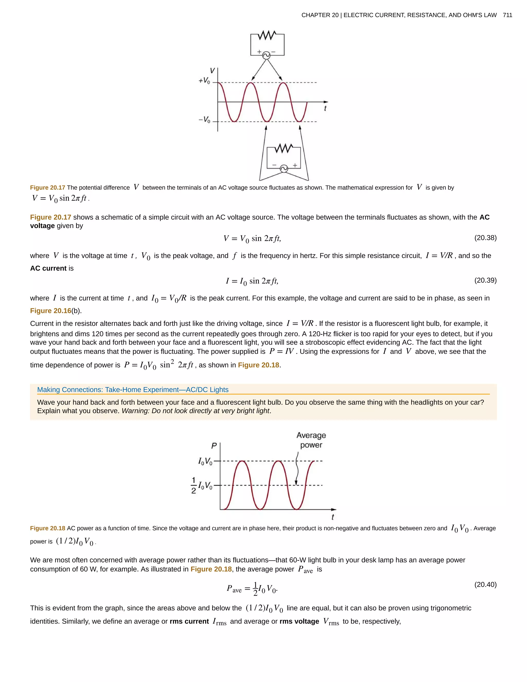

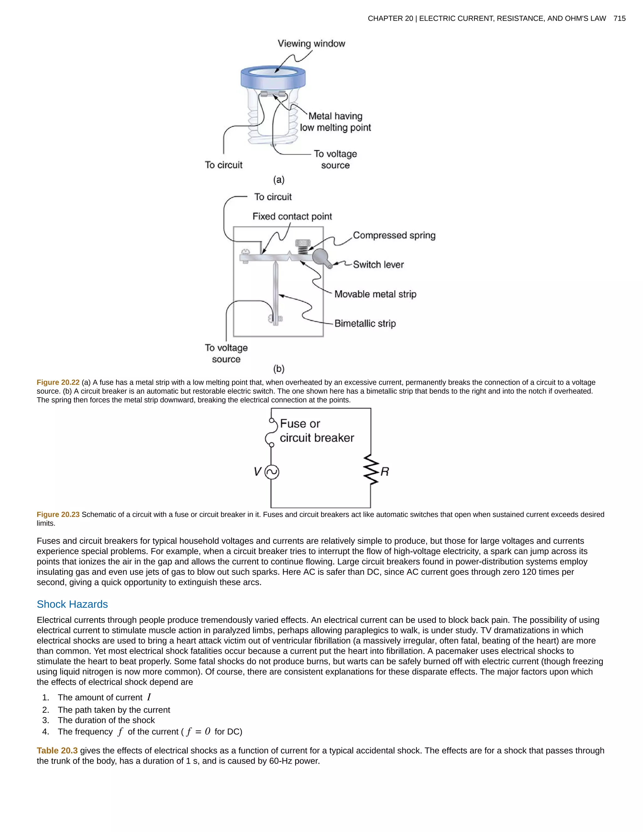
![Figure 20.24 An electric current can cause muscular contractions with varying effects. (a) The victim is “thrown” backward by involuntary muscle contractions that extend the
legs and torso. (b) The victim can’t let go of the wire that is stimulating all the muscles in the hand. Those that close the fingers are stronger than those that open them.
Table 20.3 Effects of Electrical Shock as a Function of Current[3]
Current
(mA)
Effect
1 Threshold of sensation
5 Maximum harmless current
10–20
Onset of sustained muscular contraction; cannot let go for duration of shock; contraction of chest muscles may stop breathing during
shock
50 Onset of pain
100–300+ Ventricular fibrillation possible; often fatal
300 Onset of burns depending on concentration of current
6000 (6 A)
Onset of sustained ventricular contraction and respiratory paralysis; both cease when shock ends; heartbeat may return to normal;
used to defibrillate the heart
Our bodies are relatively good conductors due to the water in our bodies. Given that larger currents will flow through sections with lower resistance
(to be further discussed in the next chapter), electric currents preferentially flow through paths in the human body that have a minimum resistance in
a direct path to earth. The earth is a natural electron sink. Wearing insulating shoes, a requirement in many professions, prohibits a pathway for
electrons by providing a large resistance in that path. Whenever working with high-power tools (drills), or in risky situations, ensure that you do not
provide a pathway for current flow (especially through the heart).
Very small currents pass harmlessly and unfelt through the body. This happens to you regularly without your knowledge. The threshold of sensation is
only 1 mA and, although unpleasant, shocks are apparently harmless for currents less than 5 mA. A great number of safety rules take the 5-mA value
for the maximum allowed shock. At 10 to 20 mA and above, the current can stimulate sustained muscular contractions much as regular nerve
impulses do. People sometimes say they were knocked across the room by a shock, but what really happened was that certain muscles contracted,
propelling them in a manner not of their own choosing. (See Figure 20.24(a).) More frightening, and potentially more dangerous, is the “can’t let go”
effect illustrated in Figure 20.24(b). The muscles that close the fingers are stronger than those that open them, so the hand closes involuntarily on
the wire shocking it. This can prolong the shock indefinitely. It can also be a danger to a person trying to rescue the victim, because the rescuer’s
hand may close about the victim’s wrist. Usually the best way to help the victim is to give the fist a hard knock/blow/jar with an insulator or to throw an
insulator at the fist. Modern electric fences, used in animal enclosures, are now pulsed on and off to allow people who touch them to get free,
rendering them less lethal than in the past.
Greater currents may affect the heart. Its electrical patterns can be disrupted, so that it beats irregularly and ineffectively in a condition called
“ventricular fibrillation.” This condition often lingers after the shock and is fatal due to a lack of blood circulation. The threshold for ventricular
fibrillation is between 100 and 300 mA. At about 300 mA and above, the shock can cause burns, depending on the concentration of current—the
more concentrated, the greater the likelihood of burns.
Very large currents cause the heart and diaphragm to contract for the duration of the shock. Both the heart and breathing stop. Interestingly, both
often return to normal following the shock. The electrical patterns on the heart are completely erased in a manner that the heart can start afresh with
normal beating, as opposed to the permanent disruption caused by smaller currents that can put the heart into ventricular fibrillation. The latter is
something like scribbling on a blackboard, whereas the former completely erases it. TV dramatizations of electric shock used to bring a heart attack
victim out of ventricular fibrillation also show large paddles. These are used to spread out current passed through the victim to reduce the likelihood of
burns.
Current is the major factor determining shock severity (given that other conditions such as path, duration, and frequency are fixed, such as in the
table and preceding discussion). A larger voltage is more hazardous, but since I = V/R , the severity of the shock depends on the combination of
voltage and resistance. For example, a person with dry skin has a resistance of about 200 k Ω . If he comes into contact with 120-V AC, a current
I = (120 V) / (200 k Ω )= 0.6 mA passes harmlessly through him. The same person soaking wet may have a resistance of 10.0 k Ω and the
same 120 V will produce a current of 12 mA—above the “can’t let go” threshold and potentially dangerous.
Most of the body’s resistance is in its dry skin. When wet, salts go into ion form, lowering the resistance significantly. The interior of the body has a
much lower resistance than dry skin because of all the ionic solutions and fluids it contains. If skin resistance is bypassed, such as by an intravenous
3. For an average male shocked through trunk of body for 1 s by 60-Hz AC. Values for females are 60–80% of those listed.
716 CHAPTER 20 | ELECTRIC CURRENT, RESISTANCE, AND OHM'S LAW
This content is available for free at http://cnx.org/content/col11406/1.7](https://image.slidesharecdn.com/20electriccurrentresistanceohmslaw-160501120419/75/20-electric-current-resistance-ohms-law-22-2048.jpg)


This document provides an introduction to electric current, resistance, and Ohm's law. It defines electric current as the rate of flow of electric charge and discusses key concepts such as conventional current, drift velocity, resistance, and Ohm's law. The document also outlines several learning objectives related to these topics and provides examples to illustrate calculations of current, drift velocity, and the relationship between current and the number of free charges in a conductor.


![Electricity [Mind Map]](https://cdn.slidesharecdn.com/ss_thumbnails/electricitymindmap-180501154503-thumbnail.jpg?width=640&height=640&fit=bounds)