SlideShare a Scribd company logo
FUNDAMENTALS OF MACHINING
Or ORTHOGONAL MACHINING
Machining is the process of removing unwanted material from a workpiece
in the form of chips. If the workpiece is metal, the process is often called
metal cutting or metal removal.

What makes this process so unique and difficult to analyze?
BASIC MACHINING PROCESSES
TURNING PROCESS
TURNING PROCESS
1. For a turning operation, you have selected an HSS tool and turning a hot rolled free machining steel, Bhn
300. Your depth of cut will be 0.150 in. The diameter of the workpiece is 1.00 inches.
a. What speed and feed would you select for this job?
b. Using a speed of 105 sfpm and a feed of 0.015, calculate the spindle rpm for this operation.
c. Calculate the metal removal rate.
d. Calculate the cutting time for the operation with a length of cut of 4 in. and .10-in. allowance.
MILLING PROCESS
MILLING PROCESS
MILLING PROCESS
2. For a slab milling operation using a 5-in.-diameter, 11-tooth cutter. the feed per
tooth is 0.005 in./tooth with a cutting speed of 100 sfpm (HSS steel). Calculate the
rpm of the cutter and the feed rate (fm) of the table, then calculate the metal removal
rate, MRR, where the width of the block being machined is 2 in. and the depth of cut
is 0.25 in. Calculate the time to machine (Tm) a 6-in.-long block of metal with this
Setup. Suppose you switched to a coated-carbide tool, so you increase the cutting
speed to 400 sfpm. Now recalculate the machining time (Tm) with all the other
parameters the same.
DRILLING PROCESS

D = diameter of the
drill which rotates 2
cutting edges at rpm
Ns.
V = velocity of
outer edge of the lip of
the drill.
Ns = 12V/ΠD.
Tm = cutting time
= (L + A)/frNs
.

where fr is the feed rate in in. per rev. The allowance A = D/2.
The MRR =
which is approximately 3DVfr
3. The power required to machine metal is related to the cutting force (Fc) and the
cutting speed. For Problem 1, estimate cutting force Fc for this turning operation.
(Hint:You have to estimate a value of HPs for this material.)
4. In order to drill a hole in the material described in Problem 1 using an HSS drill, you
have to select a cutting speed and a feed rate. Using a speed of 105 sfpm for the HSS drill,
calculate the rpm for a -in.-diameter drill and the MRR if the feed rate is 0.008 inches per
revolution.
BROACHING PROCESS

The Tm for broaching is Tm = L /12V.
The MRR (per tooth) is 12tWV in.3/min
where V = cutting velocity in fpm,
W is the width of cut, t = rise per tooth.
Usually, 30 to 40% of the total energy goes into friction and 60 to 70% into the
shear process.
Doubling speed or depth of cut
In general, increasing the speed, the feed, or the depth of cut will increase the power
requirement. Doubling the speed doubles the horsepower directly. Doubling the feed
or the depth of cut doubles the cutting force Fc. In general, increasing the speed does
not increase the cutting force Fc, a surprising experimental result.
However, speed has a strong effect on tool life because most of the input energy is
converted into heat, which raises the temperature of the chip, the work, and the tool,
which effect the tool life.
The angle that the tool makes with respect to a vertical from the workpiece is called
the back rake angle a. A positive angle is shown in the schematic. The chip is formed by
shearing. The onset of shear occurs at a low boundary deformed by angle f with respect
to the horizontal.
In metal cutting, we observe that the onset of shear (to form the chip) is delayed by
increased hardness (so f increases directly with hardness).
If the work material has hard second-phase particles dispersed in it, they can act as
barriers to the shear front dislocations, which cannot penetrate the particle. The
dislocations create voids around the particles. If there are enough particles of the right
size and shape, the chip will fracture through the shear zone, forming segmented chips.
Free-machining steels, which have small percentages of hard second-phase particles
added to them, use this metallurgical phenomenon to break up the chips for easier chip
handling.
MERCHANT MODEL
The shear angle can be measured statically by instantaneously interrupting the cut
through the use of quick-stop devices. These devices disengage the cutting tool from
the workpiece while cutting is in progress, leaving the chip attached to the workpiece.
Optical and scanning electron microscopy is then used to observe the direction of
shear.
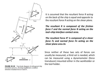
It is assumed that the resultant force R acting
on the back of the chip is equal and opposite to
the resultant force R acting on the shear plane.
The resultant R is composed of the friction
force F and the normal force N acting on the
tool–chip interface contact area.
The resultant force R’ is composed of a shear
force Fs and normal force Fn acting on the
shear plane area As
Since neither of these two sets of forces can
usually be measured, a third set is needed, which
can be measured using a dynamometer (force
transducer) mounted either in the workholder or
the tool holder.
The only symbol in this figure as
yet undefined is b, which is the
angle between the normal force
N and the resultant R. It is called
friction angle b and is used to
describe the friction coefficient
m on the tool–chip interface area,
which is defined as F/N so that
Unit power is sensitive to material properties (e.g., hardness), rake angle,
depth of cut, and feed, whereas ts is sensitive to material properties only.
CHATTER
LOBE DIAGRAM

The amplitude of chatter vibration may be more safely limited by temporary
reduction of the feed per tooth until a preferred speed and stable depth of cut have
been established.
SHAPING PROCESS
311 chapter 20
311 chapter 20
311 chapter 20
311 chapter 20
311 chapter 20
311 chapter 20
311 chapter 20
311 chapter 20
311 chapter 20
311 chapter 20
311 chapter 20
311 chapter 20
311 chapter 20
311 chapter 20
311 chapter 20
311 chapter 20
311 chapter 20
311 chapter 20
311 chapter 20
311 chapter 20
311 chapter 20
311 chapter 20
311 chapter 20
311 chapter 20
311 chapter 20
311 chapter 20
311 chapter 20
311 chapter 20
311 chapter 20
311 chapter 20
311 chapter 20

More Related Content

What's hot

Chips formation
Chips formationChips formation
Chips formation
ankit singh
 
U4 p4 sheet metal operation
U4 p4 sheet metal operationU4 p4 sheet metal operation
U4 p4 sheet metal operation
gautam buddha university
 
Unit 2 Machinability, Cutting Fluids, Tool Life & Wear, Tool Materials
Unit 2 Machinability, Cutting Fluids, Tool Life & Wear, Tool MaterialsUnit 2 Machinability, Cutting Fluids, Tool Life & Wear, Tool Materials
Unit 2 Machinability, Cutting Fluids, Tool Life & Wear, Tool Materials
Mechbytes
 
Mechanics of chips formation
Mechanics of chips formationMechanics of chips formation
Mechanics of chips formation
Hashim Hasnain Hadi
 
Lathe
LatheLathe
Metal forming processes with analysis
Metal forming processes with analysisMetal forming processes with analysis
Metal forming processes with analysis
GK Arunachalam
 
Jig & fixture
Jig & fixtureJig & fixture
Jig & fixture
Laxmi Kant Sethi
 
Metal forming processes
Metal forming processesMetal forming processes
Metal forming processes
Er Deepak Sharma
 
Manufacturing Engineering 2, cutting tools and tool holders
Manufacturing Engineering 2, cutting tools and tool holdersManufacturing Engineering 2, cutting tools and tool holders
Manufacturing Engineering 2, cutting tools and tool holders
Gaurav Mistry
 
Theory of bending
Theory of bendingTheory of bending
Theory of bending
Purnesh Aloni
 
Shaper, Planer and Slotter
Shaper, Planer and SlotterShaper, Planer and Slotter
Shaper, Planer and Slotter
Avinash Navin
 
Cutting tools
Cutting toolsCutting tools
Cutting tools
Ravi Sankar
 
Merchant Circle Diagram
Merchant Circle DiagramMerchant Circle Diagram
Merchant Circle Diagram
Manthan Kanani
 
Merchants circle-diagram
Merchants circle-diagramMerchants circle-diagram
Merchants circle-diagram
cpandiv
 
Tool wear, tool life & machinability
Tool wear, tool life & machinabilityTool wear, tool life & machinability
Tool wear, tool life & machinability
DENNY OTTARACKAL
 
heat in metal cutting
heat in metal cuttingheat in metal cutting
heat in metal cutting
Rania Atia
 
ch11.pptx
ch11.pptxch11.pptx
ch11.pptx
TsnmAlsd
 
super plastic forming- rubber pad forming
super plastic forming- rubber pad formingsuper plastic forming- rubber pad forming
super plastic forming- rubber pad forming
Pravinkumar
 
Study of cutting tools & jig fixture
Study of cutting tools & jig fixtureStudy of cutting tools & jig fixture
Study of cutting tools & jig fixture
AnujKSingh
 
ORBITAL FORGING
ORBITAL FORGINGORBITAL FORGING
ORBITAL FORGING
Shashank Kulshrestha
 

What's hot (20)

Chips formation
Chips formationChips formation
Chips formation
 
U4 p4 sheet metal operation
U4 p4 sheet metal operationU4 p4 sheet metal operation
U4 p4 sheet metal operation
 
Unit 2 Machinability, Cutting Fluids, Tool Life & Wear, Tool Materials
Unit 2 Machinability, Cutting Fluids, Tool Life & Wear, Tool MaterialsUnit 2 Machinability, Cutting Fluids, Tool Life & Wear, Tool Materials
Unit 2 Machinability, Cutting Fluids, Tool Life & Wear, Tool Materials
 
Mechanics of chips formation
Mechanics of chips formationMechanics of chips formation
Mechanics of chips formation
 
Lathe
LatheLathe
Lathe
 
Metal forming processes with analysis
Metal forming processes with analysisMetal forming processes with analysis
Metal forming processes with analysis
 
Jig & fixture
Jig & fixtureJig & fixture
Jig & fixture
 
Metal forming processes
Metal forming processesMetal forming processes
Metal forming processes
 
Manufacturing Engineering 2, cutting tools and tool holders
Manufacturing Engineering 2, cutting tools and tool holdersManufacturing Engineering 2, cutting tools and tool holders
Manufacturing Engineering 2, cutting tools and tool holders
 
Theory of bending
Theory of bendingTheory of bending
Theory of bending
 
Shaper, Planer and Slotter
Shaper, Planer and SlotterShaper, Planer and Slotter
Shaper, Planer and Slotter
 
Cutting tools
Cutting toolsCutting tools
Cutting tools
 
Merchant Circle Diagram
Merchant Circle DiagramMerchant Circle Diagram
Merchant Circle Diagram
 
Merchants circle-diagram
Merchants circle-diagramMerchants circle-diagram
Merchants circle-diagram
 
Tool wear, tool life & machinability
Tool wear, tool life & machinabilityTool wear, tool life & machinability
Tool wear, tool life & machinability
 
heat in metal cutting
heat in metal cuttingheat in metal cutting
heat in metal cutting
 
ch11.pptx
ch11.pptxch11.pptx
ch11.pptx
 
super plastic forming- rubber pad forming
super plastic forming- rubber pad formingsuper plastic forming- rubber pad forming
super plastic forming- rubber pad forming
 
Study of cutting tools & jig fixture
Study of cutting tools & jig fixtureStudy of cutting tools & jig fixture
Study of cutting tools & jig fixture
 
ORBITAL FORGING
ORBITAL FORGINGORBITAL FORGING
ORBITAL FORGING
 

Similar to 311 chapter 20

Theory of metal cutting
Theory of metal cuttingTheory of metal cutting
Theory of metal cutting
Muhammad Muddassir
 
1theoryofmetalcutting 130917122754-phpapp02
1theoryofmetalcutting 130917122754-phpapp021theoryofmetalcutting 130917122754-phpapp02
1theoryofmetalcutting 130917122754-phpapp02
manojkumarg1990
 
99992012 amu.pdf
99992012 amu.pdf99992012 amu.pdf
99992012 amu.pdf
VivekChawla19
 
Cutting tools
Cutting toolsCutting tools
38
3838
Theory of Metal Cutting.pdf
Theory of Metal Cutting.pdfTheory of Metal Cutting.pdf
Theory of Metal Cutting.pdf
DEBOLINA MUKHERJEE
 
Merchant's circle
Merchant's circleMerchant's circle
Merchant's circle
Sumit Shrivastava
 
non traditional machining
non traditional machiningnon traditional machining
non traditional machiningKhalid Sheikh
 
Merchant circle.ppt
Merchant circle.pptMerchant circle.ppt
Merchant circle.ppt
Elavarasan S
 
Production technology Metal Cutting introduction
Production technology Metal Cutting introductionProduction technology Metal Cutting introduction
Production technology Metal Cutting introduction
Ahmedabad Institute Of Technology
 
Merchant circle cutting force anlysis
Merchant circle  cutting force anlysisMerchant circle  cutting force anlysis
Merchant circle cutting force anlysis
Binit Kumar
 
Machining
MachiningMachining
Machining
NickHakimTV
 
Fundamentals of Metal Cutting 2.ppt
Fundamentals of Metal Cutting 2.pptFundamentals of Metal Cutting 2.ppt
Fundamentals of Metal Cutting 2.ppt
Ramesh S P Ramesh
 
Lecture 4
Lecture 4Lecture 4
Lecture 4
krupal3
 
Merchant circle.pptx
Merchant circle.pptxMerchant circle.pptx
Merchant circle.pptx
subir datta
 
Mechanism of Metal cutting
Mechanism of Metal cuttingMechanism of Metal cutting
Mechanism of Metal cutting
Adil Malik
 
Ipecmanuscunit1 150825052256-lva1-app6891
Ipecmanuscunit1 150825052256-lva1-app6891Ipecmanuscunit1 150825052256-lva1-app6891
Ipecmanuscunit1 150825052256-lva1-app6891
manojkumarg1990
 
Ipec manu scunit1
Ipec manu scunit1Ipec manu scunit1
Ipec manu scunit1
Manoj Yadav
 
Metal Forming, Production Engineering II
Metal Forming, Production Engineering IIMetal Forming, Production Engineering II
Metal Forming, Production Engineering II
ዘረአዳም ዘመንቆረር
 
Mechanics of metal cutting
Mechanics of metal cuttingMechanics of metal cutting
Mechanics of metal cuttingmanoj18biet
 

Similar to 311 chapter 20 (20)

Theory of metal cutting
Theory of metal cuttingTheory of metal cutting
Theory of metal cutting
 
1theoryofmetalcutting 130917122754-phpapp02
1theoryofmetalcutting 130917122754-phpapp021theoryofmetalcutting 130917122754-phpapp02
1theoryofmetalcutting 130917122754-phpapp02
 
99992012 amu.pdf
99992012 amu.pdf99992012 amu.pdf
99992012 amu.pdf
 
Cutting tools
Cutting toolsCutting tools
Cutting tools
 
38
3838
38
 
Theory of Metal Cutting.pdf
Theory of Metal Cutting.pdfTheory of Metal Cutting.pdf
Theory of Metal Cutting.pdf
 
Merchant's circle
Merchant's circleMerchant's circle
Merchant's circle
 
non traditional machining
non traditional machiningnon traditional machining
non traditional machining
 
Merchant circle.ppt
Merchant circle.pptMerchant circle.ppt
Merchant circle.ppt
 
Production technology Metal Cutting introduction
Production technology Metal Cutting introductionProduction technology Metal Cutting introduction
Production technology Metal Cutting introduction
 
Merchant circle cutting force anlysis
Merchant circle  cutting force anlysisMerchant circle  cutting force anlysis
Merchant circle cutting force anlysis
 
Machining
MachiningMachining
Machining
 
Fundamentals of Metal Cutting 2.ppt
Fundamentals of Metal Cutting 2.pptFundamentals of Metal Cutting 2.ppt
Fundamentals of Metal Cutting 2.ppt
 
Lecture 4
Lecture 4Lecture 4
Lecture 4
 
Merchant circle.pptx
Merchant circle.pptxMerchant circle.pptx
Merchant circle.pptx
 
Mechanism of Metal cutting
Mechanism of Metal cuttingMechanism of Metal cutting
Mechanism of Metal cutting
 
Ipecmanuscunit1 150825052256-lva1-app6891
Ipecmanuscunit1 150825052256-lva1-app6891Ipecmanuscunit1 150825052256-lva1-app6891
Ipecmanuscunit1 150825052256-lva1-app6891
 
Ipec manu scunit1
Ipec manu scunit1Ipec manu scunit1
Ipec manu scunit1
 
Metal Forming, Production Engineering II
Metal Forming, Production Engineering IIMetal Forming, Production Engineering II
Metal Forming, Production Engineering II
 
Mechanics of metal cutting
Mechanics of metal cuttingMechanics of metal cutting
Mechanics of metal cutting
 

Recently uploaded

Home assignment II on Spectroscopy 2024 Answers.pdf
Home assignment II on Spectroscopy 2024 Answers.pdfHome assignment II on Spectroscopy 2024 Answers.pdf
Home assignment II on Spectroscopy 2024 Answers.pdf
Tamralipta Mahavidyalaya
 
Palestine last event orientationfvgnh .pptx
Palestine last event orientationfvgnh .pptxPalestine last event orientationfvgnh .pptx
Palestine last event orientationfvgnh .pptx
RaedMohamed3
 
Sha'Carri Richardson Presentation 202345
Sha'Carri Richardson Presentation 202345Sha'Carri Richardson Presentation 202345
Sha'Carri Richardson Presentation 202345
beazzy04
 
The approach at University of Liverpool.pptx
The approach at University of Liverpool.pptxThe approach at University of Liverpool.pptx
The approach at University of Liverpool.pptx
Jisc
 
Supporting (UKRI) OA monographs at Salford.pptx
Supporting (UKRI) OA monographs at Salford.pptxSupporting (UKRI) OA monographs at Salford.pptx
Supporting (UKRI) OA monographs at Salford.pptx
Jisc
 
Additional Benefits for Employee Website.pdf
Additional Benefits for Employee Website.pdfAdditional Benefits for Employee Website.pdf
Additional Benefits for Employee Website.pdf
joachimlavalley1
 
Overview on Edible Vaccine: Pros & Cons with Mechanism
Overview on Edible Vaccine: Pros & Cons with MechanismOverview on Edible Vaccine: Pros & Cons with Mechanism
Overview on Edible Vaccine: Pros & Cons with Mechanism
DeeptiGupta154
 
Template Jadual Bertugas Kelas (Boleh Edit)
Template Jadual Bertugas Kelas (Boleh Edit)Template Jadual Bertugas Kelas (Boleh Edit)
Template Jadual Bertugas Kelas (Boleh Edit)
rosedainty
 
The Roman Empire A Historical Colossus.pdf
The Roman Empire A Historical Colossus.pdfThe Roman Empire A Historical Colossus.pdf
The Roman Empire A Historical Colossus.pdf
kaushalkr1407
 
How to Create Map Views in the Odoo 17 ERP
How to Create Map Views in the Odoo 17 ERPHow to Create Map Views in the Odoo 17 ERP
How to Create Map Views in the Odoo 17 ERP
Celine George
 
aaaaaaaaaaaaaaaaaaaaaaaaaaaaaaaaaaaaaaaaa
aaaaaaaaaaaaaaaaaaaaaaaaaaaaaaaaaaaaaaaaaaaaaaaaaaaaaaaaaaaaaaaaaaaaaaaaaaaaaaaaaa
aaaaaaaaaaaaaaaaaaaaaaaaaaaaaaaaaaaaaaaaa
siemaillard
 
Students, digital devices and success - Andreas Schleicher - 27 May 2024..pptx
Students, digital devices and success - Andreas Schleicher - 27 May 2024..pptxStudents, digital devices and success - Andreas Schleicher - 27 May 2024..pptx
Students, digital devices and success - Andreas Schleicher - 27 May 2024..pptx
EduSkills OECD
 
How to Make a Field invisible in Odoo 17
How to Make a Field invisible in Odoo 17How to Make a Field invisible in Odoo 17
How to Make a Field invisible in Odoo 17
Celine George
 
How to Split Bills in the Odoo 17 POS Module
How to Split Bills in the Odoo 17 POS ModuleHow to Split Bills in the Odoo 17 POS Module
How to Split Bills in the Odoo 17 POS Module
Celine George
 
Chapter 3 - Islamic Banking Products and Services.pptx
Chapter 3 - Islamic Banking Products and Services.pptxChapter 3 - Islamic Banking Products and Services.pptx
Chapter 3 - Islamic Banking Products and Services.pptx
Mohd Adib Abd Muin, Senior Lecturer at Universiti Utara Malaysia
 
The Challenger.pdf DNHS Official Publication
The Challenger.pdf DNHS Official PublicationThe Challenger.pdf DNHS Official Publication
The Challenger.pdf DNHS Official Publication
Delapenabediema
 
The Art Pastor's Guide to Sabbath | Steve Thomason
The Art Pastor's Guide to Sabbath | Steve ThomasonThe Art Pastor's Guide to Sabbath | Steve Thomason
The Art Pastor's Guide to Sabbath | Steve Thomason
Steve Thomason
 
PART A. Introduction to Costumer Service
PART A. Introduction to Costumer ServicePART A. Introduction to Costumer Service
PART A. Introduction to Costumer Service
PedroFerreira53928
 
aaaaaaaaaaaaaaaaaaaaaaaaaaaaaaaaaaaaaaaaaaaaaaaaaaaaaaa
aaaaaaaaaaaaaaaaaaaaaaaaaaaaaaaaaaaaaaaaaaaaaaaaaaaaaaaaaaaaaaaaaaaaaaaaaaaaaaaaaaaaaaaaaaaaaaaaaaaaaaaaaaaaaa
aaaaaaaaaaaaaaaaaaaaaaaaaaaaaaaaaaaaaaaaaaaaaaaaaaaaaaa
siemaillard
 
The geography of Taylor Swift - some ideas
The geography of Taylor Swift - some ideasThe geography of Taylor Swift - some ideas
The geography of Taylor Swift - some ideas
GeoBlogs
 

Recently uploaded (20)

Home assignment II on Spectroscopy 2024 Answers.pdf
Home assignment II on Spectroscopy 2024 Answers.pdfHome assignment II on Spectroscopy 2024 Answers.pdf
Home assignment II on Spectroscopy 2024 Answers.pdf
 
Palestine last event orientationfvgnh .pptx
Palestine last event orientationfvgnh .pptxPalestine last event orientationfvgnh .pptx
Palestine last event orientationfvgnh .pptx
 
Sha'Carri Richardson Presentation 202345
Sha'Carri Richardson Presentation 202345Sha'Carri Richardson Presentation 202345
Sha'Carri Richardson Presentation 202345
 
The approach at University of Liverpool.pptx
The approach at University of Liverpool.pptxThe approach at University of Liverpool.pptx
The approach at University of Liverpool.pptx
 
Supporting (UKRI) OA monographs at Salford.pptx
Supporting (UKRI) OA monographs at Salford.pptxSupporting (UKRI) OA monographs at Salford.pptx
Supporting (UKRI) OA monographs at Salford.pptx
 
Additional Benefits for Employee Website.pdf
Additional Benefits for Employee Website.pdfAdditional Benefits for Employee Website.pdf
Additional Benefits for Employee Website.pdf
 
Overview on Edible Vaccine: Pros & Cons with Mechanism
Overview on Edible Vaccine: Pros & Cons with MechanismOverview on Edible Vaccine: Pros & Cons with Mechanism
Overview on Edible Vaccine: Pros & Cons with Mechanism
 
Template Jadual Bertugas Kelas (Boleh Edit)
Template Jadual Bertugas Kelas (Boleh Edit)Template Jadual Bertugas Kelas (Boleh Edit)
Template Jadual Bertugas Kelas (Boleh Edit)
 
The Roman Empire A Historical Colossus.pdf
The Roman Empire A Historical Colossus.pdfThe Roman Empire A Historical Colossus.pdf
The Roman Empire A Historical Colossus.pdf
 
How to Create Map Views in the Odoo 17 ERP
How to Create Map Views in the Odoo 17 ERPHow to Create Map Views in the Odoo 17 ERP
How to Create Map Views in the Odoo 17 ERP
 
aaaaaaaaaaaaaaaaaaaaaaaaaaaaaaaaaaaaaaaaa
aaaaaaaaaaaaaaaaaaaaaaaaaaaaaaaaaaaaaaaaaaaaaaaaaaaaaaaaaaaaaaaaaaaaaaaaaaaaaaaaaa
aaaaaaaaaaaaaaaaaaaaaaaaaaaaaaaaaaaaaaaaa
 
Students, digital devices and success - Andreas Schleicher - 27 May 2024..pptx
Students, digital devices and success - Andreas Schleicher - 27 May 2024..pptxStudents, digital devices and success - Andreas Schleicher - 27 May 2024..pptx
Students, digital devices and success - Andreas Schleicher - 27 May 2024..pptx
 
How to Make a Field invisible in Odoo 17
How to Make a Field invisible in Odoo 17How to Make a Field invisible in Odoo 17
How to Make a Field invisible in Odoo 17
 
How to Split Bills in the Odoo 17 POS Module
How to Split Bills in the Odoo 17 POS ModuleHow to Split Bills in the Odoo 17 POS Module
How to Split Bills in the Odoo 17 POS Module
 
Chapter 3 - Islamic Banking Products and Services.pptx
Chapter 3 - Islamic Banking Products and Services.pptxChapter 3 - Islamic Banking Products and Services.pptx
Chapter 3 - Islamic Banking Products and Services.pptx
 
The Challenger.pdf DNHS Official Publication
The Challenger.pdf DNHS Official PublicationThe Challenger.pdf DNHS Official Publication
The Challenger.pdf DNHS Official Publication
 
The Art Pastor's Guide to Sabbath | Steve Thomason
The Art Pastor's Guide to Sabbath | Steve ThomasonThe Art Pastor's Guide to Sabbath | Steve Thomason
The Art Pastor's Guide to Sabbath | Steve Thomason
 
PART A. Introduction to Costumer Service
PART A. Introduction to Costumer ServicePART A. Introduction to Costumer Service
PART A. Introduction to Costumer Service
 
aaaaaaaaaaaaaaaaaaaaaaaaaaaaaaaaaaaaaaaaaaaaaaaaaaaaaaa
aaaaaaaaaaaaaaaaaaaaaaaaaaaaaaaaaaaaaaaaaaaaaaaaaaaaaaaaaaaaaaaaaaaaaaaaaaaaaaaaaaaaaaaaaaaaaaaaaaaaaaaaaaaaaa
aaaaaaaaaaaaaaaaaaaaaaaaaaaaaaaaaaaaaaaaaaaaaaaaaaaaaaa
 
The geography of Taylor Swift - some ideas
The geography of Taylor Swift - some ideasThe geography of Taylor Swift - some ideas
The geography of Taylor Swift - some ideas
 

311 chapter 20

  • 1. FUNDAMENTALS OF MACHINING Or ORTHOGONAL MACHINING
  • 2. Machining is the process of removing unwanted material from a workpiece in the form of chips. If the workpiece is metal, the process is often called metal cutting or metal removal. What makes this process so unique and difficult to analyze?
  • 3.
  • 6.
  • 9.
  • 10. 1. For a turning operation, you have selected an HSS tool and turning a hot rolled free machining steel, Bhn 300. Your depth of cut will be 0.150 in. The diameter of the workpiece is 1.00 inches. a. What speed and feed would you select for this job? b. Using a speed of 105 sfpm and a feed of 0.015, calculate the spindle rpm for this operation. c. Calculate the metal removal rate. d. Calculate the cutting time for the operation with a length of cut of 4 in. and .10-in. allowance.
  • 14. 2. For a slab milling operation using a 5-in.-diameter, 11-tooth cutter. the feed per tooth is 0.005 in./tooth with a cutting speed of 100 sfpm (HSS steel). Calculate the rpm of the cutter and the feed rate (fm) of the table, then calculate the metal removal rate, MRR, where the width of the block being machined is 2 in. and the depth of cut is 0.25 in. Calculate the time to machine (Tm) a 6-in.-long block of metal with this Setup. Suppose you switched to a coated-carbide tool, so you increase the cutting speed to 400 sfpm. Now recalculate the machining time (Tm) with all the other parameters the same.
  • 15. DRILLING PROCESS D = diameter of the drill which rotates 2 cutting edges at rpm Ns. V = velocity of outer edge of the lip of the drill. Ns = 12V/ΠD. Tm = cutting time = (L + A)/frNs . where fr is the feed rate in in. per rev. The allowance A = D/2. The MRR = which is approximately 3DVfr
  • 16.
  • 17. 3. The power required to machine metal is related to the cutting force (Fc) and the cutting speed. For Problem 1, estimate cutting force Fc for this turning operation. (Hint:You have to estimate a value of HPs for this material.)
  • 18. 4. In order to drill a hole in the material described in Problem 1 using an HSS drill, you have to select a cutting speed and a feed rate. Using a speed of 105 sfpm for the HSS drill, calculate the rpm for a -in.-diameter drill and the MRR if the feed rate is 0.008 inches per revolution.
  • 19. BROACHING PROCESS The Tm for broaching is Tm = L /12V. The MRR (per tooth) is 12tWV in.3/min where V = cutting velocity in fpm, W is the width of cut, t = rise per tooth.
  • 20.
  • 21.
  • 22.
  • 23.
  • 24.
  • 25. Usually, 30 to 40% of the total energy goes into friction and 60 to 70% into the shear process.
  • 26. Doubling speed or depth of cut In general, increasing the speed, the feed, or the depth of cut will increase the power requirement. Doubling the speed doubles the horsepower directly. Doubling the feed or the depth of cut doubles the cutting force Fc. In general, increasing the speed does not increase the cutting force Fc, a surprising experimental result. However, speed has a strong effect on tool life because most of the input energy is converted into heat, which raises the temperature of the chip, the work, and the tool, which effect the tool life.
  • 27.
  • 28. The angle that the tool makes with respect to a vertical from the workpiece is called the back rake angle a. A positive angle is shown in the schematic. The chip is formed by shearing. The onset of shear occurs at a low boundary deformed by angle f with respect to the horizontal.
  • 29. In metal cutting, we observe that the onset of shear (to form the chip) is delayed by increased hardness (so f increases directly with hardness).
  • 30. If the work material has hard second-phase particles dispersed in it, they can act as barriers to the shear front dislocations, which cannot penetrate the particle. The dislocations create voids around the particles. If there are enough particles of the right size and shape, the chip will fracture through the shear zone, forming segmented chips. Free-machining steels, which have small percentages of hard second-phase particles added to them, use this metallurgical phenomenon to break up the chips for easier chip handling.
  • 32. The shear angle can be measured statically by instantaneously interrupting the cut through the use of quick-stop devices. These devices disengage the cutting tool from the workpiece while cutting is in progress, leaving the chip attached to the workpiece. Optical and scanning electron microscopy is then used to observe the direction of shear.
  • 33. It is assumed that the resultant force R acting on the back of the chip is equal and opposite to the resultant force R acting on the shear plane. The resultant R is composed of the friction force F and the normal force N acting on the tool–chip interface contact area. The resultant force R’ is composed of a shear force Fs and normal force Fn acting on the shear plane area As Since neither of these two sets of forces can usually be measured, a third set is needed, which can be measured using a dynamometer (force transducer) mounted either in the workholder or the tool holder.
  • 34. The only symbol in this figure as yet undefined is b, which is the angle between the normal force N and the resultant R. It is called friction angle b and is used to describe the friction coefficient m on the tool–chip interface area, which is defined as F/N so that
  • 35.
  • 36. Unit power is sensitive to material properties (e.g., hardness), rake angle, depth of cut, and feed, whereas ts is sensitive to material properties only.
  • 37.
  • 38.
  • 40.
  • 41.
  • 42.
  • 43. LOBE DIAGRAM The amplitude of chatter vibration may be more safely limited by temporary reduction of the feed per tooth until a preferred speed and stable depth of cut have been established.