Download to read offline
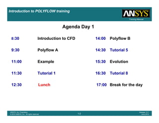
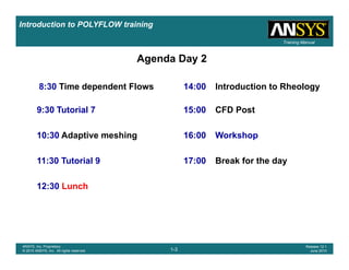
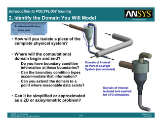
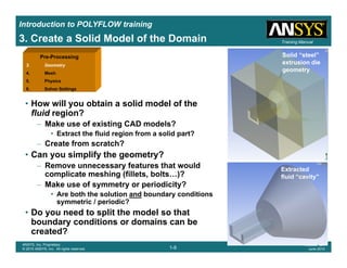
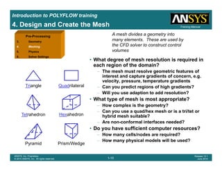
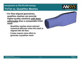
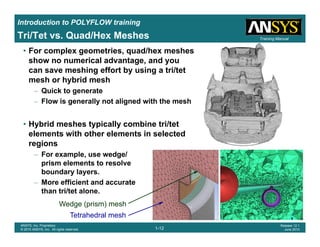
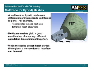
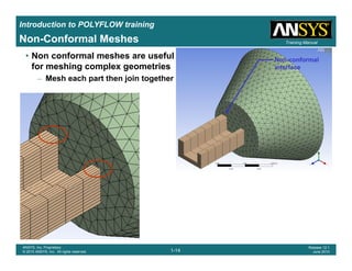
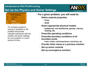
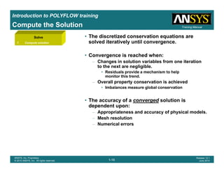
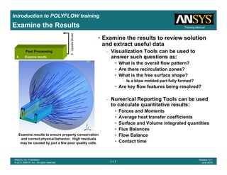
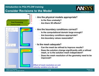
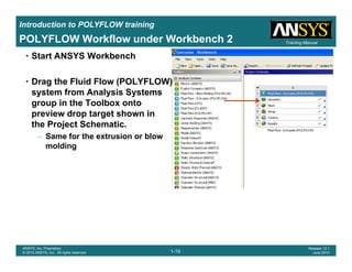
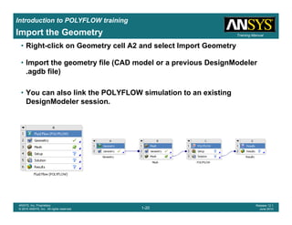
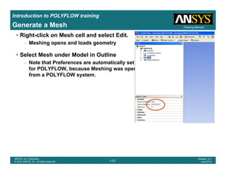
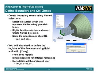
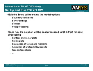

This document outlines an agenda and introduction for a POLYFLOW training over two days. Day 1 will cover introductions to CFD and POLYFLOW, tutorials, and examples. Day 2 will cover time dependent flows, rheology, CFD post-processing, and workshops. The introduction defines CFD and the governing equations solved. It describes the CFD modeling process including defining goals, geometry, meshing, setting physics models and boundary conditions, and examining results. It covers topics like mesh types, setting up multi-zone meshes, and non-conformal interfaces.