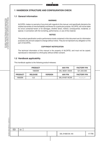
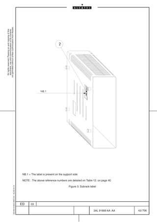
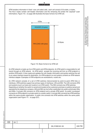
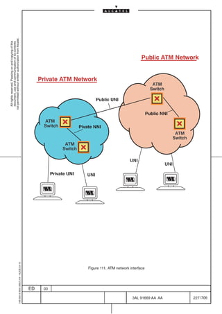
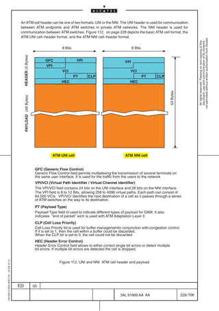
This document is a technical handbook for the Alcatel 1660SM STM 64 Multiservice Metro Node. It provides information on safety norms and labels, electromagnetic compatibility, a list of abbreviations used, general information on Alcatel customer documentation, and detailed descriptions of the equipment. The handbook guides installation, commissioning, operation and maintenance of the 1660SM node. It has been updated through three editions to include new information and corrections.


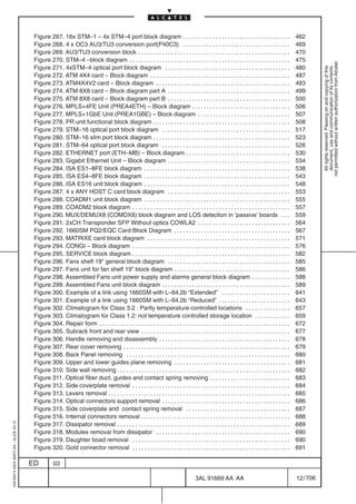


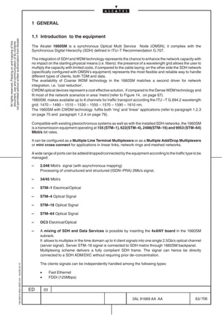
![1.3 Product-release handbooks
The list of handbooks given here below is valid on the issue date of this Handbook and
can be changed without any obligation for ALCATEL to update it in this Handbook.
not permitted without written authorization from Alcatel.
All rights reserved. Passing on and copying of this
document, use and communication of its contents
Some of the handbooks listed here below may not be available on the issue date of this
Handbook.
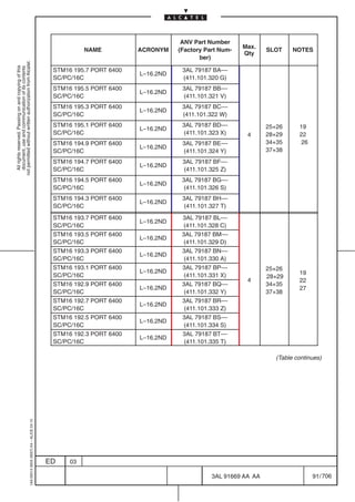
The standard Customer Documentation in the English language for the equipment whose
product-release-version is stated in para.1.2 on page 17 consists of the following handbooks:
Table 1. Handbooks related to the specific product hardware
THIS
REF HANDBOOK ANV Part No.
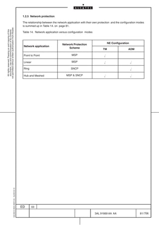
HDBK
1660SM Rel.5.2
3AL 91669 AAAA
Technical Handbook
[1]
Provide information regarding Equipment description, Maintenance , Hardware
setting documentation
1660SM Rel.5.2
3AL 91669 BAAA
Installation Handbook
[2]
Provide information regarding Equipment Installation, according to A–Installation
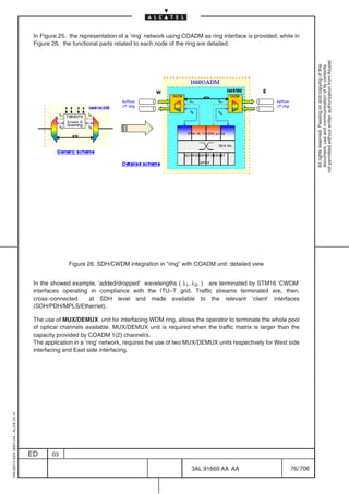
Engineering Department rules.
1660SM Rel.5.2
3AL91669 CAAA
Turnup & Commissionig Handbook
[3]
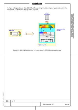
Provide information regarding Equipment Turn–On, Test and Operation,
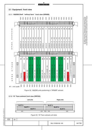
according to A–Installation Engineering Department rules.
Table 2. Handbooks related to the specific product SW management and local product control
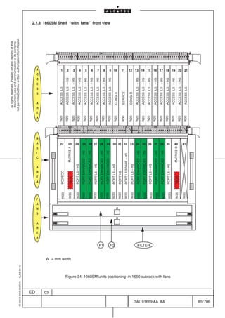
THIS
REF HANDBOOK ANV Part No. HDBK
or note
Metro OMSN Rel.4.4/5.2
3AL 91670 AAAA
CT Operator’s Handbook
[4]
Provides 1660SM “SDH” Craft Terminal screens and operational procedures
1AA 00014 0004 (9007) A4 – ALICE 04.10
ED 03
3AL 91669 AA AA 18 / 706
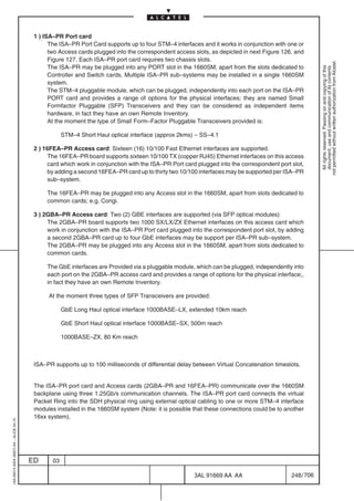
706](https://image.slidesharecdn.com/1660smtecr5-2ed03-100224044520-phpapp01/85/1660-S-M-Tec-R5-20-320.jpg)
![Table 3. Handbooks related to ATM specific product SW
THIS
REF HANDBOOK ANV Part No. HDBK
not permitted without written authorization from Alcatel.
or note
All rights reserved. Passing on and copying of this
document, use and communication of its contents
ATM Rel.1.2
[5] 3AL 80814 AAAA
Operator’s Handbook
ATM Rel.2.0
[6] 3AL 81826 AAAA
Operator’s Handbook
ATM Rel.2.1
[7] 3AL 89777 AAAA
Operator’s Handbook
ATM Rel.2.2
[8] 3AL 91714 AAAA
Operator’s Handbook
Provides ATM Craft Terminal screens and operational procedures
Table 4. Handbooks related to PR_EA specific product SW
THIS
REF HANDBOOK ANV Part No. HDBK
or note
PR_EA Rel.1.1
[9] 3AL 81062 BAAA
Operator’s Handbook
Provides PR_EA Terminal screens and operational procedures
Table 5. Handbooks related to PR specific product SW
THIS
REF HANDBOOK ANV Part No. HDBK
or note
PR Rel.1.0
[10] 3AL 81771 AAAA
Operator’s Handbook
PR Rel.1.1
[11] 3AL 91658 AAAA
Operator’s Handbook
PR Rel.1.2
[12] 3AL 91715 AAAA
Operator’s Handbook
Provides PR Craft Terminal screens and operational procedures
1AA 00014 0004 (9007) A4 – ALICE 04.10
ED 03
3AL 91669 AA AA 19 / 706
706](https://image.slidesharecdn.com/1660smtecr5-2ed03-100224044520-phpapp01/85/1660-S-M-Tec-R5-21-320.jpg)
![Table 6. Handbooks related to ISA ES specific product SW
THIS
REF HANDBOOK ANV Part No.
not permitted without written authorization from Alcatel.
HDBK
All rights reserved. Passing on and copying of this
document, use and communication of its contents
or note
ES1 Rel.1.0
[13] 3AL 89872 AAAA
Operator’s Handbook
ES1/ES4 Rel.1.1
[14] 3AL 89871 AAAA
Operator’s Handbook
ES1/ES4 Rel.1.2
[15] 3AL91804 AAAA
Operator’s Handbook
ES16 Rel.2.0
[16] 3AL 89870 AAAA
Operator’s Handbook
ES16 Rel.2.1
[17] 3AL 91716 AAAA
Operator’s Handbook
Provides ISA–ES Craft Terminal screens and operational procedures
1AA 00014 0004 (9007) A4 – ALICE 04.10
ED 03
3AL 91669 AA AA 20 / 706
706](https://image.slidesharecdn.com/1660smtecr5-2ed03-100224044520-phpapp01/85/1660-S-M-Tec-R5-22-320.jpg)
![Table 7. Handbooks common to Alcatel Network Elements using 1320CT platform
FACTORY THIS
REF HANDBOOK ANV Part No.
Part No. HDBK
not permitted without written authorization from Alcatel.
All rights reserved. Passing on and copying of this
document, use and communication of its contents
1320CT 3.x
3AL 79551 AAAA 957.140.042 N
Basic Operator’s Handbook
[18]
Provides general information and operational procedures common to all
1320CT (Craft terminal) of Alcatel InfoModel Network Elements.
1330AS Rel.6.5
3AL 88876 AAAA ––––––––
Operator’s Handbook
Provides detailed information and operational procedures regarding the alarm
[19]
Surveillance software embedded in the 1320CT software package.
Information about Historical Alarms an Network Element Symbols
Management ( Physical Network Management) are not valid for Craft Terminal.
They are only used by Network Management.
ELB Rel.2.x Operator’s Handbook 3AL 88877 AAAA ––––––––
[20]
Provide detailed information and operational procedures regarding the Event
Log Browser software embedded in the 1320CT software package.
1AA 00014 0004 (9007) A4 – ALICE 04.10
ED 03
3AL 91669 AA AA 21 / 706
706](https://image.slidesharecdn.com/1660smtecr5-2ed03-100224044520-phpapp01/85/1660-S-M-Tec-R5-23-320.jpg)
![Table 8. Optional handbooks common to 16xxSM
FACTORY THIS
REF HANDBOOK ANV Part No.
Part No. HDBK
not permitted without written authorization from Alcatel.
All rights reserved. Passing on and copying of this
document, use and communication of its contents
S9–16xxSM
3AL 78901 AAAA 955.100.692 N
System Installation Handbook
[21]
Provides general installation rules necessary to install the Optinex family
equipment in the S9 Rack.
Optinex RACK–16xxSM
3AL 38207 AAAA 955.110.202 L
System Installation Handbook
[22]
Provides general installation rules necessary to install the Optinex family
equipment in the Optinex Rack.
N.B. Handbooks REF. [21] and [22] are available only on paper support
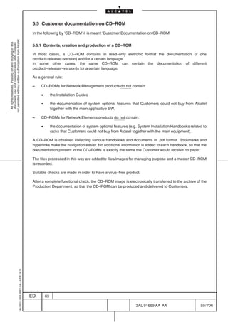
Table 9. Documentation on CD–ROM
See para. 5.5 on page 59
REF CD–ROM TITLE ANV Part No. FACTORY Part No.
1660SM Rel.5.2 CD–ROM–DOC EN 3AL 91671 AAAA ––.––.––
[23]
Contains, in electronic format, the following handbooks: REF. [1] to [4]
1320CT 3.x BASIC CD–ROM–DOC EN 3AL 79552 AAAA 417.100.032
[24]
Contains, in electronic format, the following handbooks: REF. [18] to [20]
ATM 1.2 CD–ROM–DOC EN 3AL 80815 AAAA ––.––.––
[25]
Contains, in electronic format, the following handbooks: REF. [5]
ATM 2.0 CD–ROM–DOC EN 3AL 81829 AAAA ––.––.––
[26]
Contains, in electronic format, the following handbook: REF. [6]
ATM 2.1 CD–ROM–DOC EN 3AL 89778 AAAA ––.––.––
[27]
Contains, in electronic format, the following handbooks: REF. [7]
ATM 2.2 CD–ROM–DOC EN 3AL 91717 AAAA ––.––.––
1AA 00014 0004 (9007) A4 – ALICE 04.10
[28]
Contains, in electronic format, the following handbooks: REF. [8]
ED 03
3AL 91669 AA AA 22 / 706
706](https://image.slidesharecdn.com/1660smtecr5-2ed03-100224044520-phpapp01/85/1660-S-M-Tec-R5-24-320.jpg)
![REF CD–ROM TITLE ANV Part No. FACTORY Part No.
PR_EA 1.1 CD–ROM–DOC EN 3AL 81063 BAAA ––.––.––
not permitted without written authorization from Alcatel.
[29]
All rights reserved. Passing on and copying of this
document, use and communication of its contents
Contains, in electronic format, the following handbook: REF. [9]
PR 1.0 CD–ROM–DOC EN 3AL 81769 AAAA ––.––.––
[30]
Contains, in electronic format, the following handbook: REF. [10]
PR 1.1 CD–ROM–DOC EN 3AL 91659 AAAA ––.––.––
[31]
Contains, in electronic format, the following handbooks: REF. [11]
PR 1.2 CD–ROM–DOC EN 3AL 91718 AAAA ––.––.––
[32]
Contains, in electronic format, the following handbooks: REF. [12]
ES1 1.0 CD–ROM–DOC EN 3AL 89875 AAAA ––.––.––
[33]
Contains, in electronic format, the following handbooks: REF. [13]
ES1/ES4 1.1 CD–ROM–DOC EN 3AL 89874 AAAA ––.––.––
[34]
Contains, in electronic format, the following handbooks: REF. [14]
ES1/ES4 1.2 CD–ROM–DOC EN 3AL91805 AAAA ––.––.––
[35]
Contains, in electronic format, the following handbooks: REF. [15]
ES16 2.0 CD–ROM–DOC EN 3AL 89873 AAAA ––.––.––
[36]
Contains, in electronic format, the following handbooks: REF. [16]
ES16 2.1 CD–ROM–DOC EN 3AL 91719 AAAA ––.––.––
[37]
Contains, in electronic format, the following handbooks: REF. [17]
1AA 00014 0004 (9007) A4 – ALICE 04.10
ED 03
3AL 91669 AA AA 23 / 706
706](https://image.slidesharecdn.com/1660smtecr5-2ed03-100224044520-phpapp01/85/1660-S-M-Tec-R5-25-320.jpg)


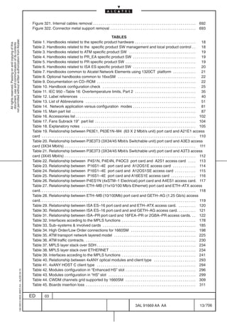
![Table 20. Relationship between P3E3T3 (3X34/45 Mbit/s Switchable unit) port card and A3E3 access
card (3X34 Mbit/s)
Port Card acronym Port Card Slot Access Card acronym Access Card Slot
not permitted without written authorization from Alcatel.
All rights reserved. Passing on and copying of this
document, use and communication of its contents
P3E3T3 24 A3E3 2 (CH. 1–3)
P3E3T3 25 A3E3 3 (CH. 1–3)
P3E3T3 26 A3E3 4 (CH. 1–3)
P3E3T3 27 A3E3 5 (CH. 1–3)
P3E3T3 28 A3E3 6 (CH. 1–3)
P3E3T3 29 A3E3 7 (CH. 1–3)
P3E3T3 30 A3E3 8 (CH. 1–3)
P3E3T3 31 A3E3 9 (CH. 1–3)
P3E3T3 32 A3E3 13 (CH. 1–3)
P3E3T3 33 A3E3 14 (CH. 1–3)
P3E3T3 34 A3E3 15 (CH. 1–3)
P3E3T3 35 A3E3 16 (CH. 1–3)
P3E3T3 36 A3E3 17 (CH. 1–3)
P3E3T3 37 A3E3 18 (CH. 1–3)
P3E3T3 38 A3E3 19 (CH. 1–3)
P3E3T3 39 A3E3 20 (CH. 1–3)
One or more 1+N (N ≤15) EPS revertive protection scheme can be created (for more detail see point [3]
of para. 3.13.1 on page 322).
In case of EPS configuration the following configuration rules must be respected:
– Insert the protecting port card in a slot at the most left of of the protected port cards group.
– Insert the special protection access card (HPROT) associated to the protecting port card
following the rule reported in Table 20. on page 111 ( for example if the “protecting port card” has
been inserted in slot 24, the ” protection access card HPROT” must be inserted in slot 2).
The max. number of EPS groups is 8 i.e. 8 cards each protected 1+1 revertive. For each group a HPROT
access card is required therefore the max number of HPROT access cards is 8.
1AA 00014 0004 (9007) A4 – ALICE 04.10
ED 03
3AL 91669 AA AA 111 / 706
706](https://image.slidesharecdn.com/1660smtecr5-2ed03-100224044520-phpapp01/85/1660-S-M-Tec-R5-113-320.jpg)
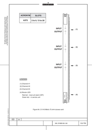
![Table 21. Relationship between P3E3T3 (3X34/45 Mbit/s Switchable unit) port card and A3T3 access
card (3X45 Mbit/s)
Port Card acronym Port Card Slot Access Card acronym Access Card Slot
not permitted without written authorization from Alcatel.
All rights reserved. Passing on and copying of this
document, use and communication of its contents
P3E3T3 24 A3T3 2 (CH. 1–3)
P3E3T3 25 A3T3 3 (CH. 1–3)
P3E3T3 26 A3T3 4 (CH. 1–3)
P3E3T3 27 A3T3 5 (CH. 1–3)
P3E3T3 28 A3T3 6 (CH. 1–3)
P3E3T3 29 A3T3 7 (CH. 1–3)
P3E3T3 30 A3T3 8 (CH. 1–3)
P3E3T3 31 A3T3 9 (CH. 1–3)
P3E3T3 32 A3T3 13 (CH. 1–3)
P3E3T3 33 A3T3 14 (CH. 1–3)
P3E3T3 34 A3T3 15 (CH. 1–3)
P3E3T3 35 A3T3 16 (CH. 1–3)
P3E3T3 36 A3T3 17 (CH. 1–3)
P3E3T3 37 A3T3 18 (CH. 1–3)
P3E3T3 38 A3T3 19 (CH. 1–3)
P3E3T3 39 A3T3 20 (CH. 1–3)
One or more 1+N (N ≤15) EPS revertive protection scheme can be created (for more detail see point [3]
of para. 3.13.1 on page 322).
In case of EPS configuration the following configuration rules must be respected:
– Insert the protecting port card in a slot at the most left of of the protected port cards group.
– Insert the special protection access card (HPROT) associated to the protecting port card
following the rule reported in Table 20. on page 111 ( for example if the “protecting port card” has
been inserted in slot 24, the ” protection access card HPROT” must be inserted in slot 2).
The max. number of EPS groups is 8 i.e. 8 cards each protected 1+1 revertive. For each group a HPROT
access card is required therefore the max number of HPROT access cards is 8.
1AA 00014 0004 (9007) A4 – ALICE 04.10
ED 03
3AL 91669 AA AA 112 / 706
706](https://image.slidesharecdn.com/1660smtecr5-2ed03-100224044520-phpapp01/85/1660-S-M-Tec-R5-114-320.jpg)
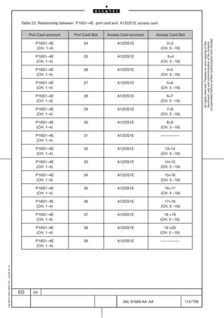
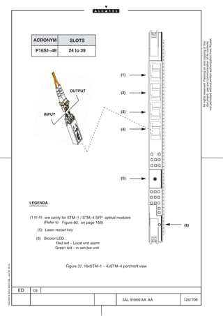
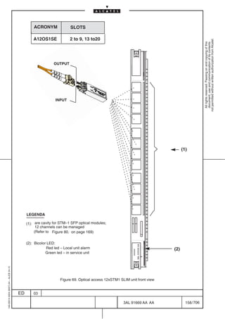
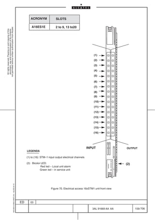
![Table 25. Relationship between P16S1–4E port card and A16ES1E access card
Port Card acronym Port Card Slot Access Card acronym Access Card Slot
not permitted without written authorization from Alcatel.
P16S1–4E 24 A16ES1E 2 (CH. 1 – 16)
All rights reserved. Passing on and copying of this
document, use and communication of its contents
P16S1–4E 25 A16ES1E 3 (CH. 1 – 16)
P16S1–4E 26 A16ES1E 4 (CH. 1 – 16)
P16S1–4E 27 A16ES1E 5 (CH. 1 – 16)
P16S1–4E 28 A16ES1E 6 (CH. 1 – 16)
P16S1–4E 29 A16ES1E 7 (CH. 1 – 16)
P16S1–4E 30 A16ES1E 8 (CH. 1 – 16)
P16S1–4E 31 A16ES1E 9 (CH. 1 – 16)
P16S1–4E 32 A16ES1E 13 (CH. 1 – 16)
P16S1–4E 33 A16ES1E 14 (CH. 1 – 16)
P16S1–4E 34 A16ES1E 15 (CH. 1 – 16)
P16S1–4E 35 A16ES1E 16 (CH. 1 – 16)
P16S1–4E 36 A16ES1E 17 (CH. 1 – 16)
P16S1–4E 37 A16ES1E 18 (CH. 1 – 16)
P16S1–4E 38 A16ES1E 19 (CH. 1 – 16)
P16S1–4E 39 A16ES1E 20 (CH. 1 – 16)
One or more 1+N (N ≤15) EPS revertive protection scheme can be created (for more detail see point [3]
of para. 3.13.1 on page 322).
In case of EPS configuration the following configuration rules must be respected:
– Insert the protecting port card in a slot at the most left of of the protected port cards group.
– Insert the special protection access card (HPROT) associated to the protecting port card
following the rule reported in Table 25. on page 116 ( for example if the “protecting port card” has
been inserted in slot 24, the ” protection access card HPROT” must be inserted in slot 2).
The max. number of EPS groups is 8 i.e. 8 cards each protected 1+1 revertive. For each group a HPROT
access card is required therefore the max number of HPROT access cards is 8.
1AA 00014 0004 (9007) A4 – ALICE 04.10
ED 03
3AL 91669 AA AA 116 / 706
706](https://image.slidesharecdn.com/1660smtecr5-2ed03-100224044520-phpapp01/85/1660-S-M-Tec-R5-118-320.jpg)
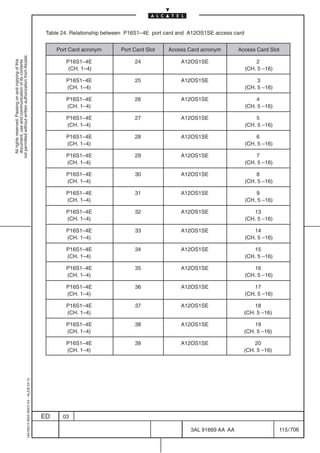
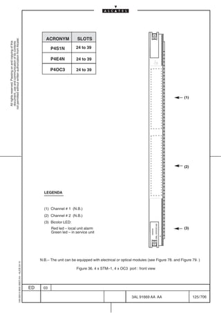
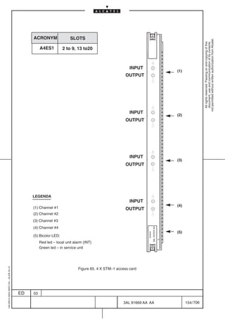
![Table 26. Relationship between P4ES1N (4xSTM–1 Electrical) port card and A4ES1 access card.
Port Card acronym Port Card Slot Access Card acronym Access Card Slot
P4ES1N 24 A4ES1 2 (CH. 1 to 4)
not permitted without written authorization from Alcatel.
All rights reserved. Passing on and copying of this
document, use and communication of its contents
P4ES1N 25 A4ES1 3 (CH. 1 to 4)
P4ES1N 26 A4ES1 4 (CH. 1 to 4)
P4ES1N 27 A4ES1 5 (CH. 1 to 4)
P4ES1N 28 A4ES1 6 (CH. 1 to 4)
P4ES1N 29 A4ES1 7 (CH. 1 to 4)
P4ES1N 30 A4ES1 8 (CH. 1 to 4)
P4ES1N 31 A4ES1 9 (CH. 1 to 4)
P4ES1N 32 A4ES1 13 (CH. 1 to 4)
P4ES1N 33 A4ES1 14 (CH. 1 to 4)
P4ES1N 34 A4ES1 15 (CH. 1 to 4)
P4ES1N 35 A4ES1 16 (CH. 1 to 4)
P4ES1N 36 A4ES1 17 (CH. 1 to 4)
P4ES1N 37 A4ES1 18 (CH. 1 to 4)
P4ES1N 38 A4ES1 19 (CH. 1 to 4)
P4ES1N 39 A4ES1 20 (CH. 1 to 4)
One or more 1+N (N ≤15) EPS revertive protection scheme can be created (for more detail see point [3]
of para. 3.13.1 on page 322).
In case of EPS configuration the following configuration rules must be respected:
– Insert the protecting port card in a slot at the most left of of the protected port cards group.
– Insert the special protection access card (HPROT) associated to the protecting port card
following the rule reported in Table 20. on page 111 ( for example if the “protecting port card” has
been inserted in slot 24, the ” protection access card HPROT” must be inserted in slot 2).
The max. number of EPS groups is 8 i.e. 8 cards each protected 1+1 revertive. For each group a HPROT
access card is required therefore the max number of HPROT access cards is 8.
The STM–4 and STM–16 high speed port card does not need Access Card because the physical
termination of the channel is on the port itself.
1AA 00014 0004 (9007) A4 – ALICE 04.10
ED 03
3AL 91669 AA AA 117 / 706
706](https://image.slidesharecdn.com/1660smtecr5-2ed03-100224044520-phpapp01/85/1660-S-M-Tec-R5-119-320.jpg)


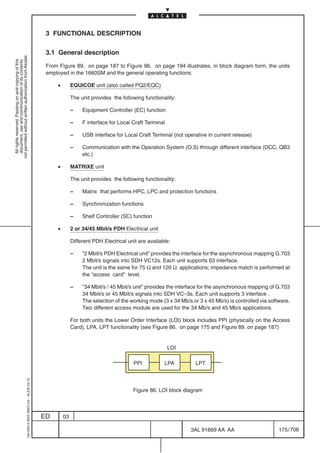


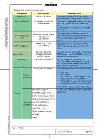
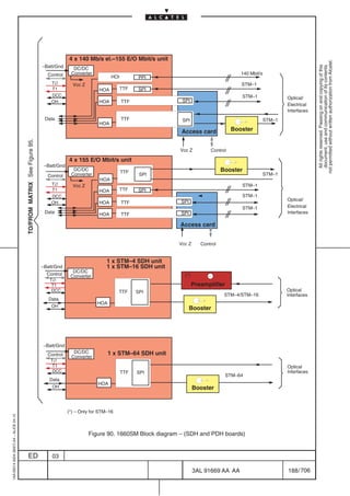
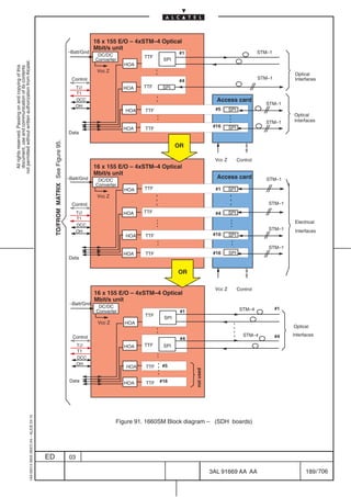
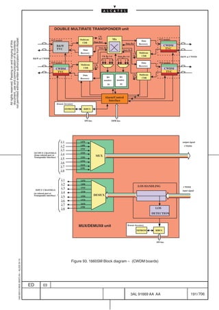
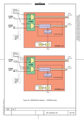
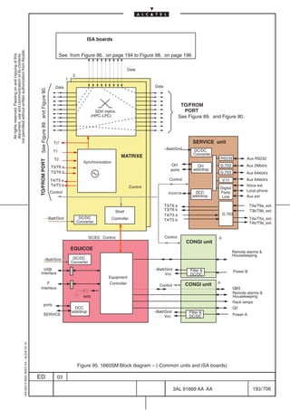
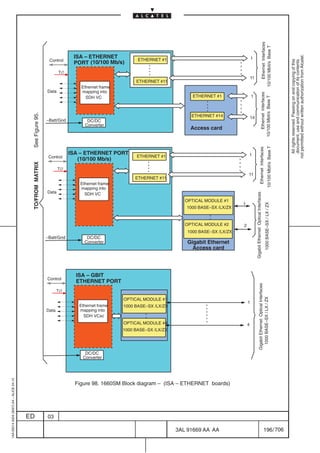
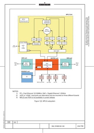
![The functions carried out by the unit can be splitted into the following sub–systems:
[1] Connections sub–system (see paragraph 3.2 on page 198)
not permitted without written authorization from Alcatel.
[2] Signal management sub–system (see paragraph 3.3 on page 200)
All rights reserved. Passing on and copying of this
document, use and communication of its contents
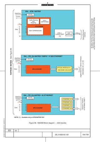
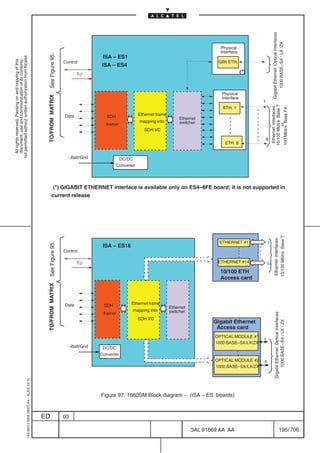
[3] ISA (Integrated Service Adapter) sub–system ( refer to paragraph 3.4 on page 223)
[4] 4xANY HOST C subs–system (see paragraph 3.10 on page 293)
[5] Coarse WDM sub–system (refer to paragraph 3.11 on page 300)
[6] Controller sub–system (see paragraph 3.12 on page 315)
[7] Protection sub–system (see paragraph 3.13 on page 321)
[8] Synchronization sub–system (see paragraph 3.14 on page 363)
[9] Auxiliary sub–system (see paragraph 3.15 on page 365)
[10] Power supply sub–system (see paragraph 3.16 on page 367)
[11] Remote inventory sub–system (see paragraph 3.17 on page 370)
On the following paragraphs a detailed description of each sub–system is given.
Each logical function does not correspond necessarily to a physical card but can be distributed over more
than one card. On the other side, one card can house more than one function.
For each sub–system the list of the involved cards and a brief abstract of the function detailed on the
following paragraphs is reported in Table 33. on page 185.
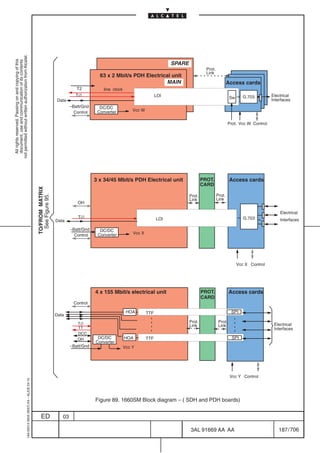
Notice that the On Board Power Supply (DC/DC converter in Figure 89. on page 187) is present on each
card and that the Controller function is centralized ( EC and SC).
1AA 00014 0004 (9007) A4 – ALICE 04.10
ED 03
3AL 91669 AA AA 184 / 706
706](https://image.slidesharecdn.com/1660smtecr5-2ed03-100224044520-phpapp01/85/1660-S-M-Tec-R5-186-320.jpg)

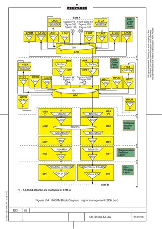
![3.3.4 SIGNAL MANAGEMENT referred to ”G. 783”
The ITU–T G.783 Recommendation describe the SDH characteristic in terms of atomic functions.
This paragraph has been introduced as an aid to the understanding of the terms used for the Termination
not permitted without written authorization from Alcatel.
Point (T.P.). These TPs can be accessed and managed by the operator for performance monitoring
All rights reserved. Passing on and copying of this
document, use and communication of its contents
purpose .
In the following will be explained the atomic functions naming conventions and the signal processing in
the SDH and PDH port .
3.3.5 ATOMIC FUNCTION NAMING CONVENTIONS
Each characteristic layer of the SDH network is splitted into different atomic functions :
– trail termination function :
• Source (So): additional information is added to the characteristic information to allow trail
monitoring.
• Sink (Sk): the information related to the trail monitoring is extracted
If a signal fail condition of the associated data signal is detected, a TSF signal is generated to
inform the next downstream function. TSF is use in the HPOM (Snm) function to drive the
SNCP/MSP protection.
– adaptation function :
• Source (So):the characteristic information is adapted from the client to the server layer
• Sink (Sk): the characteristic information is adapted from the server to the client layer
The processes present in an adaptation function can be : encoding, rate changing, alignment,
justification, multiplexing.
If a signal fail condition of the associated data signal is detected, a SSF signal is generated to
inform the next downstream function.
– connection function : it represents the connection functions inside the network ( link
connection, sub–network network connection) and it is performed by the matrix functional block
Each atomic function is represented by a different symbol and named as follow:
– trail termination TT : triangle
Sink Source
naming rules: layer_TT[ _direction] example: OSn_TT[ _Sk]
– adaptation A : trapezium
Sink Source
naming rules: layer/client layer_A[direction] example: OSn/RSn_A[Sk]
1AA 00014 0004 (9007) A4 – ALICE 04.10
– connection C: circle or ellipse
naming rules: layer_C example: Sm_C
ED 03
3AL 91669 AA AA 206 / 706
706](https://image.slidesharecdn.com/1660smtecr5-2ed03-100224044520-phpapp01/85/1660-S-M-Tec-R5-208-320.jpg)
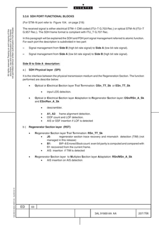
![c) Multiplex Section layer :
• Multiplex Section layer Trail Termination (MST): MSn_TT_Sk
•
not permitted without written authorization from Alcatel.
B2: BIP–24N Errored Block count ––Ex–BER, Signal Degrade alarm
All rights reserved. Passing on and copying of this
document, use and communication of its contents
• M1: MS–REI recovery.
• K2[6–8]: MS–RDI detection.
• K2[6–8]: MS–AIS detection.
• Multiplex Section Sub–layer Protection function (MSP):
– Multiplex Section layer to the Multiplex Section Protection Sub–layer Adaptation:
MSn/MSnP_A_Sk
• the K1–K2 information (APS protocol) is recovered .
• AIS or SSF insertion
– Multiplex Section Protection Sub–layer Trail Termination: MSnP_TT_Sk
• AIS or SSF detection
• TSF insertion (on SSF detection)
• Multiplex Section layer Adaptation to the High Order Path layer (MSA): MSn/Sn_A_Sk
• AU–4 Pointer interpreter.
• LOP detection
• AU–AIS detection
• AIS or SSF insertion (on LOP and AU–AIS detection)
• PJE (Pointer Justification Event) count.
d) High Order Path layer:
• High Order Path Overhead Monitoring Function (HPOM)
– High Order Path Overhead Trail Termination: Snm_TT_Sk
• J1: Path Trace information is recovered.
• G1[1–4]: The REI information is recovered.
• G1[5]: Path Status monitoring –– HP–RDI detection.
• C2: Signal Label Monitoring –– UNEQ and VC–AIS detection.
• B3: VC–4 BIP–8 Errored Block Count –– Ex–BER and Signal Degrade alarm
• TSF insertion
• TSD insertion
TSF and TSD are used for SNCP switch
• High Order Supervisory Unequipped Termination
– High Order Supervisory Unequipped Trail Termination (HSUT): Sns_TT_Sk
• J1: Path Trace information is recovered.
• G1[1–4]: The REI information is recovered.
• G1[5]: Path Status monitoring ––HP–RDI detection.
• C2: Signal Label Monitoring –– UNEQ and VC–AIS detection.
• B3: VC–4 BIP–8 Errored Block Count.
1AA 00014 0004 (9007) A4 – ALICE 04.10
ED 03
3AL 91669 AA AA 208 / 706
706](https://image.slidesharecdn.com/1660smtecr5-2ed03-100224044520-phpapp01/85/1660-S-M-Tec-R5-210-320.jpg)
![• High Order Path Tandem Connection Trail Termination (according to Option 2 TC described in
Recc. ITU–T G.707)
– High Order Path Tandem Connection Termination (HTCT): SnD_TT_Sk
not permitted without written authorization from Alcatel.
All rights reserved. Passing on and copying of this
document, use and communication of its contents
• N1[1–4]: VC–4 BIP–8 extraction and EDC calculation.
• N1[8][73]: RDI extraction.
• N1[5]: REI extraction.
• N1[7][74]: ODI extraction (Outgoing Defect Indication).
• N1[6]: OEI extraction (Outgoing Error Indication)
• N1[7–8]: extraction from the multiframed channel N1[7–8] of:
FAS (Frame Alignment Signal) in frames 1 to 8.
trace identifier in frames 9 to 72.
TC RDI and ODI in frames 73 to 76.
• B3: BIP–8 compensation.
• High Order Path Tandem Connection Adaptation (according to Option 2 TC described in Recc.
ITU–T G.707)
– High Order Path Tandem Connection Adaptation (HTCA): SnD/Sn_A_Sk
this function will restore the invalid Frame Start condition if that existed at the iput of the
tandem connection.
AIS insertion.
• High Order Path Tandem Connection Monitoring (according to Option 2 TC described in Recc.
ITU–T G.707)
– High Order Path Tandem Connection Monitoring (HTCM): SnDm_TT_Sk
• N1[1–4]: VC–4 BIP–8 extraction and EDC calculation.
• N1[8][73]: RDI extraction.
• N1[5]: REI extraction.
• N1[7][74]: ODI extraction (Outgoing Defect Indication).
• N1[6]: OEI extraction (Outgoing Error Indication)
• N1[7–8]: extraction from the multiframed channel N1[7–8] of:
FAS (Frame Alignment Signal) in frames 1 to 8.
trace identifier in frames 9 to 72.
TC RDI and ODI in frames 73 to 76.
1AA 00014 0004 (9007) A4 – ALICE 04.10
ED 03
3AL 91669 AA AA 209 / 706
706](https://image.slidesharecdn.com/1660smtecr5-2ed03-100224044520-phpapp01/85/1660-S-M-Tec-R5-211-320.jpg)
![• High Order Path layer Trail Termination Function (HPT): Sn_TT_Sk
• J1: Path Trace information is recovered –– TIM detection.
• G1[1–4]: The REI information is recovered.
not permitted without written authorization from Alcatel.
• G1[5]: Path Status monitoring ––HP–RDI detection.
All rights reserved. Passing on and copying of this
document, use and communication of its contents
• C2: UNEQ detection.
• B3: VC–4 BIP–8 Errored Block Count –– Ex–BER, Signal Degrade alarm
• High Order Path layer Adaptation to Low Order Path layer (HPA): Sn/Sm_A_Sk
• VC–4 disassembly.
• TU pointer interpretation.
• LOP detection.
• TU–AIS detection.
• C2: HP–SLM (signal label mismatch) detection.
• H4: LOM (Loss of Multiframe) detection.
e) Low Order Path layer:
• Low Order Path Overhead Monitoring Function (LPOM)
– Low Order Path Overhead Trail Termination: Smm_TT_Sk
• J2: Trace Identifier Monitoring.
• V5[8]: RDI information is recovered and reported.
• V5[3]: REI bit is recovered and the derived performance primitives are reported.
• V5[5–7]: Signal Label Monitoring –– VC–AIS detection.
• V5[1,2]: VC–m BIP–2 Errored Block Count ––Ex–BER, Signal Degrade alarm
• AIS or SSF detection––SSF alarm
• TSF insertion (used for SNCP switch)
• Low Order Supervisory Unequipped Termination (LSUT)
– Low Order Supervisory Unequipped Trail Termination: Sms_TT_Sk
• V5[5–7]: signal label is recovered from the VC–m. 000 (unequipped) is expected.
• J2: trail trace identifier is recovered.
• V5[1,2]: BIP–2 is recovered.
• V5[3]: REI bit is recovered and the derived performance primitives is reported.
• V5[8]: RDI information is recovered and reported.
1AA 00014 0004 (9007) A4 – ALICE 04.10
ED 03
3AL 91669 AA AA 210 / 706
706](https://image.slidesharecdn.com/1660smtecr5-2ed03-100224044520-phpapp01/85/1660-S-M-Tec-R5-212-320.jpg)
![• Low Order Path Tandem Connection Trail Termination (according to Option 2 TC described in
Recc. ITU–T G.707)
– Low Order Path Tandem Connection Termination (LTCT): SmD_TT_Sk
not permitted without written authorization from Alcatel.
All rights reserved. Passing on and copying of this
document, use and communication of its contents
• N2[1–2]: VC–12 BIP–2 extraction and EDC calculation.
• N2[8][73]: RDI extraction.
• N2[5]: REI extraction.
• N2[7][74]: ODI extraction (Outgoing Defect Indication).
• N2[6]: OEI extraction (Outgoing Error Indication)
• N2[7–8]: extraction from the multiframed channel N2[7–8] of:
FAS (Frame Alignment Signal) in frames 1 to 8.
trace identifier in frames 9 to 72.
TC RDI and ODI in frames 73 to 76.
• N2[4]: AIS detection
• V5[1–2]: BIP–2 compensation.
• Low Order Path Tandem Connection Adaptation (according to Option 2 TC described in Recc.
ITU–T G.707)
– Low Order Path Tandem Connection Adaptation (LTCA): SmD/Sm_A_Sk
this function will restore the invalid Frame Start condition if that existed at the iput of the
tandem connection.
AIS insertion.
• Low Order Path Tandem Connection Monitoring (according to Option 2 TC described in Recc.
ITU–T G.707)
– Low Order Path Tandem Connection Monitoring (LTCM): SnDm_TT_Sk
• N2[1–2]: VC–12 BIP–2 extraction and EDC calculation.
• N2[8][73]: RDI extraction.
• N2[5]: REI extraction.
• N2[7][74]: ODI extraction (Outgoing Defect Indication).
• N2[6]: OEI extraction (Outgoing Error Indication)
• N2[7–8]: extraction from the multiframed channel N2[7–8] of:
FAS (Frame Alignment Signal) in frames 1 to 8.
trace identifier in frames 9 to 72.
TC RDI and ODI in frames 73 to 76.
• N2[4]: AIS detection
1AA 00014 0004 (9007) A4 – ALICE 04.10
ED 03
3AL 91669 AA AA 211 / 706
706](https://image.slidesharecdn.com/1660smtecr5-2ed03-100224044520-phpapp01/85/1660-S-M-Tec-R5-213-320.jpg)
![Side A to Side B description:
a) Low Order Path layer:
•
not permitted without written authorization from Alcatel.
Low Order Supervisory Unequipped Termination (LSUT)
All rights reserved. Passing on and copying of this
document, use and communication of its contents
– Low Order Supervisory Unequipped Trail Termination: Sms_TT_So
• V5[5–7]: signal label 000 (unequipped) is inserted in the VC–m.
• J2: trail trace identifier is generated.
• V5[1,2]: BIP–2 is calculated and transmitted.
• V5[3]: the number of errors is encoded in REI.
• V5[8]: RDI indication is inserted.
• Low Order Path Overhead Monitoring Function (LPOM)
– Low Order Path Overhead Trail Termination: Smm_TT_Sk
• J2: Trace Identifier Monitoring.
• V5[8]: RDI information is recovered and reported.
• V5[3]: REI bit is recovered and the derived performance primitives are reported.
• V5[5–7]: Signal Label Monitoring –– VC–AIS detection.
• V5[1,2]: VC–m BIP–2 Errored Block Count –– Ex–BER, Signal Degrade alarm
• Low Order Path Tandem Connection Adaptation (according to Option 2 TC described in Recc.
ITU–T G.707)
– Low Order Path Tandem Connection Adaptation (LTCA): SmD/Sm_A_Sk
this function will restore the invalid Frame Start condition if that existed at the iput of the
tandem connection.
AIS insertion.
• Low Order Path Tandem Connection Trail Termination (according to Option 2 TC described in
Recc. ITU–T G.707)
– Low Order Path Tandem Connection Termination (LTCT): SmD_TT_So
• N2[8][73]: RDI insertion
• N2[5]: REI insertion
• N2[7][74]: ODI insertion (Outgoing Defect Indication)
• N2[6]: OEI insertion (Outgoing Error Indication)
• N2[7–8]: insertion in the multiframed channel N1[7 –8] of:
FAS (Frame Alignment Signal) in frames 1 to 8
trace identifier in frames 9 to 72
TC RDI and ODI in frames 73 to 76
• N2[1–2]: BIP–2 calculation and insertion
• V5[1–2]: BIP–2 compensation
1AA 00014 0004 (9007) A4 – ALICE 04.10
ED 03
3AL 91669 AA AA 212 / 706
706](https://image.slidesharecdn.com/1660smtecr5-2ed03-100224044520-phpapp01/85/1660-S-M-Tec-R5-214-320.jpg)
![• Low Order Path Tandem Connection Monitoring (according to Option 2 TC described in Recc.
ITU–T G.707)
– Low Order Path Tandem Connection Monitoring (LTCM): SnDm_TT_Sk
not permitted without written authorization from Alcatel.
All rights reserved. Passing on and copying of this
document, use and communication of its contents
• N2[1–2]: VC–12 BIP–2 extraction and EDC calculation.
• N2[8][73]: RDI extraction.
• N2[5]: REI extraction.
• N2[7][74]: ODI extraction (Outgoing Defect Indication).
• N2[6]: OEI extraction (Outgoing Error Indication)
• N2[7–8]: extraction from the multiframed channel N2[7–8] of:
FAS (Frame Alignment Signal) in frames 1 to 8.
trace identifier in frames 9 to 72.
TC RDI and ODI in frames 73 to 76.
• N2[4]: AIS detection
b) High Order Path layer:
• Low Order Path layer to High Order Path layer Adaptation (HPA): Sn/Sm_A_So
• VC–4 assembly.
• TU pointer generator.
• TU–AIS generator.
• C2: Signal label insertion.
• H4: Multiframe indicator
• High Order Path layer Trail Termination Function (HPT): Sn_TT_So
• J1: path trace identifier is inserted.
• G1: insertion of RDI[5] and/or REI[1–4] information.
• B3: VC–4 Bip–8 calculation and insertion.
• High Order Path Overhead Monitoring Function
– High Order Path Overhead Trail Termination (HPOM): Snm_TT_Sk
• J1: Path Trace information is recovered.
• G1[1–4]: The REI information is recovered.
• G1[5]: Path Status monitoring –– HP–RDI detection.
• C2: Signal Label Monitoring –– UNEQ and VC–AIS detection.
• B3: VC–4 BIP–8 Errored Block Count.
• AIS or SSF detection –– SSF alarm
1AA 00014 0004 (9007) A4 – ALICE 04.10
ED 03
3AL 91669 AA AA 213 / 706
706](https://image.slidesharecdn.com/1660smtecr5-2ed03-100224044520-phpapp01/85/1660-S-M-Tec-R5-215-320.jpg)
![– High Order Supervisory Unequipped Trail Termination (HSUT): Sns_TT_So
• Generation of an unequipped container and frame offset.
• C2: “unequipped” insertion.
not permitted without written authorization from Alcatel.
• J1: trail trace identifier is generated.
All rights reserved. Passing on and copying of this
document, use and communication of its contents
• G1: insertion of RDI and/or REI information.
• B3: VC–4 Bip–8 calculation and insertion.
• High Order Path Tandem Connection Adaptation (according to Option 2 TC described in Recc.
ITU–T G.707)
– High Order Path Tandem Connection Adaptation (HTCA): SnD_A_So
this function will replace the incoming Frame Start signal by a local generated one if
all–ONEs VC is received.
• High Order Path Tandem Connection Trail Termination (according to Option 2 TC described in
Recc. ITU–T G.707)
– High Order Path Tandem Connection Termination (HTCT): SnD_TT_So
• N1[8][73]: RDI insertion
• N1[5]: REI insertion
• N1[7][74]: ODI insertion (Outgoing Defect Indication)
• N1[6]: OEI insertion (Outgoing Error Indication)
• N1[7–8]: insertion in the multiframed channel N1[7 –8] of:
FAS (Frame Alignment Signal) in frames 1 to 8
trace identifier in frames 9 to 72
TC RDI and ODI in frames 73 to 76
• N1[1–4]: BIP–8 calculation and insertion
• B3: BIP–8 compensation
• High Order Path Tandem Connection Monitoring (according to Option 2 TC described in Recc.
ITU–T G.707)
– High Order Path Tandem Connection Monitoring (HTCM): SnDm_TT_Sk
• N1[1–4]: VC–4 BIP–8 extraction and EDC calculation.
• N1[8][73]: RDI extraction.
• N1[5]: REI extraction.
• N1[7][74]: ODI extraction (Outgoing Defect Indication).
• N1[6]: OEI extraction (Outgoing Error Indication)
• N1[7–8]: extraction from the multiframed channel N1[7–8] of:
FAS (Frame Alignment Signal) in frames 1 to 8.
trace identifier in frames 9 to 72.
TC RDI and ODI in frames 73 to 76.
1AA 00014 0004 (9007) A4 – ALICE 04.10
ED 03
3AL 91669 AA AA 214 / 706
706](https://image.slidesharecdn.com/1660smtecr5-2ed03-100224044520-phpapp01/85/1660-S-M-Tec-R5-216-320.jpg)
![c) Multiplex Section layer:
• Multiplex Section layer Adaptation to the High Order Path layer (MSA): MSn/Sn_A_So
•
not permitted without written authorization from Alcatel.
AUG assembly and byte interleaving.
All rights reserved. Passing on and copying of this
document, use and communication of its contents
• AU–4 Pointer generator.
• AU–AIS generator.
• Multiplex Section Sub–layer Protection function (MSP)
– Multiplex Section Protection Sub–layer Termination: MSnP_TT_So
• no information is inserted.
– Multiplex Section layer Adaptation to the Multiplex Section Protection Sub–layer:
MSn/MSnP_A_So
• generation of K1–K2 information (APS protocol).
• Multiplex Section layer Trail Termination: MSn_TT_So
• B2: BIP–24N calculation and insertion.
• M1: MS–REI insertion.
• K2[6–8]: MS–RDI insertion.
• K2[6–8]: MS–AIS insertion.
d) Regenerator Section layer (RST)
• Multiplex Section layer to Regenerator Section layer Adaptation : RSn/MSn_A_So
• RS–AIS insertion.
• Regenerator Section layer Trail Termination: RSn_TT_So
• A1, A2: frame alignment insertion.
• J0: regenerator section trace insertion (not managed in this release)
• B1: BIP–8 calculation and insertion.
e) SDH Physical layer (SPI)
It is the interface between Regeneration Section and the physical transmission medium. The function
performed are describe below:
• Optical or Electrical Section layer Adaptation to Regenerator Section layer: OSn/RSn_A_So
and ESn/Rsn_A_So:
• scrambler.
• AIS generator (on LOS or LOF).
• Optical or Electrical Section layer Trail Termination: OSn_TT _So or ESn_TT _So
• signal conditioning for transmission medium (e.g. electrical/optical conversion etc.)
1AA 00014 0004 (9007) A4 – ALICE 04.10
ED 03
3AL 91669 AA AA 215 / 706
706](https://image.slidesharecdn.com/1660smtecr5-2ed03-100224044520-phpapp01/85/1660-S-M-Tec-R5-217-320.jpg)
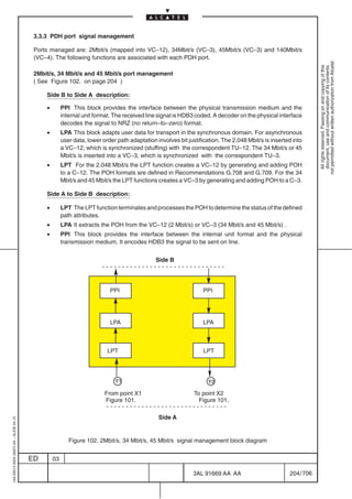
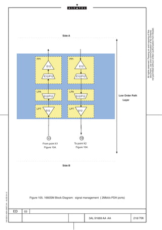
![3.3.7 PDH PORT FUNCTIONAL BLOCKS
In LC–NG PDH Low Order ports managed are 2Mbit/s (mapped into VC–12), 34Mbit/s (VC–3), 45Mbit/s
(VC–3) and 140Mbit/s (VC–4). The following functions are associated with each PDH port.
not permitted without written authorization from Alcatel.
2 MBIT/S PORT MANAGEMENT
All rights reserved. Passing on and copying of this
document, use and communication of its contents
(See Figure 105. on page 218 )
Side B to Side A description:
a) Low Order Path layer:
• Low Order Path layer Trail Termination Function (LPT): S12_TT_Sk
• J2: trail trace identifier is recovered –– TIM detection.
• V5[1,2]: BIP–2 is recovered –– Ex–BER, Signal Degrade alarm
• V5[3]: REI bit is recovered and the derived performance primitives is reported.
• V5[8]: RDI information is recovered and reported.
• AIS or SSF detection –– SSF alarm
• Low Order Path layer Adaptation to PDH Section layer (LPA): S12/P12x_A_Sk or
S12/P12s_A_Sk
• V5[5–7]: Signal label detection in the byte V5[5–7] –– Signal label Mismatch
detection
• AIS or SSF is applied if Signal label Mismatch is detected
b) Electrical PDH Physical Section layer (PPI)
• Adaptation to PDH section layer: E12/P12x_A_So or E12/P12s_A_So
• It convert the internal signal code to the line code.
• Trail Termination: E12_TT_So
• signal conditioning for transmission medium ( e.g. electrical level, etc.)
Side A to Side B description:
a) Electrical PDH Physical Section layer (PPI)
• Trail Termination: E12_TT_Sk
• input LOS detection.
• AIS insertion if LOS is detected
• PDH physical adaptation layer: E12/P12x_A_Sk or E12/P12s_A_Sk
• timing is extracted.
• data are decoded.
• AIS insertion if LOF or AIS is detected.
b) Low Order Path layer:
• PDH Section layer to Low Order Path layer Adaptation (LPA): S12/P12x_A_So or
S12/P12s_A_So
• V5[5–7]: Signal label insertion in the byte V5[5–7].
• Low Order Path layer Trail Termination function (LPT): S12_TT_So
• J2: trail trace identifier is generated.
1AA 00014 0004 (9007) A4 – ALICE 04.10
• V5[1,2]: BIP–2 is calculated and transmitted.
• V5[3]: the number of errors is encoded in REI.
• V5[8]: RDI indication is inserted.
ED 03
3AL 91669 AA AA 217 / 706
706](https://image.slidesharecdn.com/1660smtecr5-2ed03-100224044520-phpapp01/85/1660-S-M-Tec-R5-219-320.jpg)
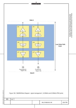
![34 MBIT/S AND 45 MBIT/S PORT MANAGEMENT
(See Figure 106. on page220 )
not permitted without written authorization from Alcatel.
Side B to Side A description:
All rights reserved. Passing on and copying of this
document, use and communication of its contents
a) Low Order Path layer:
• Low Order Path layer Trail Termination Function (LPT): S3_TT_Sk
• J1: Path Trace information is recovered –– TIM detection.
• G1[1–4]: The REI information is recovered.
• G1[5]: Path Status monitoring ––HP–RDI detection.
• C2: UNEQ detection.
• B3: VC–3 BIP–8 Errored Block Count –– Ex–BER, Signal Degrade
• SSF detection –– SSF alarm
• Low Order Path layer Adaptation to PDH Section layer (LPA): S3/P3x_A_Sk or S3/P3s_A_Sk
• C2: Signal label detection in the byte C2 – Signal label Mismatch detection.
• AIS or SSF is applied if TSF or Signal label Mismatch is detected
b) Electrical PDH Physical Section layer (PPI)
• Adaptation to PDH section layer: E3/P3x_A_So or E3/P3s_A_So
• It convert the internal signal code to the line code (HDB3)
• Trail Termination: E3_TT_So
• signal conditioning for transmission medium ( e.g. electrical level, etc.).
Side A to Side B description:
a) Electrical PDH Physical Section layer (PPI)
• Trail Termination: E3_TT_Sk
• Input LOS detection.
• PDH physical Adaptation layer: E3/P3x_A_Sk or E3/P3s_A_Sk
• timing is extracted.
• data are decoded.
• AIS detection and insertion.
• LOF detection (only in case of E3/P3x_A_Sk)
b) Low Order Path layer:
• PDH Section layer to Low Order Path layer Adaptation (LPA): S3/P3x_A_So or S3/P3s_A_So
• The signal label is inserted in C2
• Low Order Path layer Trail Termination Function (LPT): S3_TT_So
1AA 00014 0004 (9007) A4 – ALICE 04.10
• J1: path trace identifier is inserted.
• G1: insertion of RDI[5] and/or REI[1–4] information.
• B3: VC–3 Bip–8 calculation and insertion.
ED 03
3AL 91669 AA AA 219 / 706
706](https://image.slidesharecdn.com/1660smtecr5-2ed03-100224044520-phpapp01/85/1660-S-M-Tec-R5-221-320.jpg)
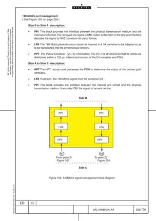
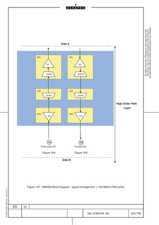
![140 MBIT/S PORT MANAGEMENT
(See Figure 107. on page 222)
not permitted without written authorization from Alcatel.
Side B to Side A description:
All rights reserved. Passing on and copying of this
document, use and communication of its contents
a) High Order Path layer:
• High Order Path layer Trail Termination Function (HPT): S4_TT_Sk
• J1: Path Trace information is recovered –– TIM detection.
• G1[1–4]: The REI information is recovered.
• G1[5]: Path Status monitoring ––HP–RDI detection.
• C2: UNEQ detection.
• B3: VC–4 BIP–8 Errored Block Count–– Ex–BER, Signal Degrade alarm
• SSF detection –– SSF alarm
• Low Order Path layer Adaptation to PDH Section layer (LPA): S4/P4x_A_Sk or S4/P4s_A_Sk
• C2: Signal label detection in the byte C2 – Signal label Mismatch detection.
• AIS or SSF is applied if TSF or Signal label Mismatch is detected
b) Electrical PDH Physical Section layer (PPI)
• Adaptation to PDH section layer:E4/P4x_A_So or E4/P4s_A_So
• It convert the internal signal code to the line code (CMI)
• Trail Termination: E4_TT_So
• signal conditioning for transmission medium ( e.g. electrical level, etc.).
Side A to Side B description:
a) Electrical PDH Physical Section layer (PPI)
• Trail Termination: E4_TT_Sk
• Input LOS detection.
• PDH physical Adaptation layer: E4/P4x_A_Sk or E4/P4s_A_Sk
• timing is extracted.
• data are decoded.
• AIS detection and insertion.
• LOF detection (only in case of E4/P4x_A_Sk)
b) Low Order Path layer:
• PDH Section layer to Low Order Path layer Adaptation (LPA): S4/P4x_A_So or S4/P4s_A_So
• The signal label is inserted in C2
• High Order Path layer Trail Termination Function (HPT): S4_TT_So
1AA 00014 0004 (9007) A4 – ALICE 04.10
• J1: path trace identifier is inserted.
• G1: insertion of RDI[5] and/or REI[1–4] information.
• B3: VC–4 Bip–8 calculation and insertion.
ED 03
3AL 91669 AA AA 221 / 706
706](https://image.slidesharecdn.com/1660smtecr5-2ed03-100224044520-phpapp01/85/1660-S-M-Tec-R5-223-320.jpg)


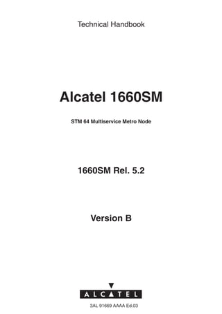
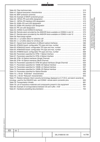
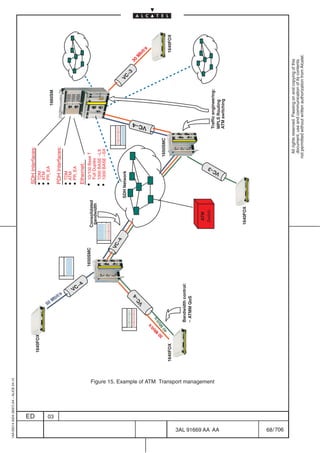
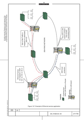
![3.5.2.6 ATM switching modules application
The main application of the ATM board is to consolidate ATM traffic collected from different sources onto
shared SDH VCs (virtual containers) in STM–n rings and to switch the ATM traffic, as needed at VP and
not permitted without written authorization from Alcatel.
/or VC level, into the network.
All rights reserved. Passing on and copying of this
document, use and communication of its contents
Wasted bandwidth
SDH circuits
E3 E3
E3 E3
E3 SDH VC–4 [3 X VC–3] E3
ADM ADM
Free bandwidth
Data flows
Consolidation
E3 E3
E3
STM–1
E3 SDH VC–4 [3 X VC–3]
E1
1660SM 1660SM
ATM board
Figure 114. Leased line service versus Data transport service
Typical applications of the atm board concept are ADSL, UMTS and LMDS metropolitan networks.
In all those scenarios the Provider can take great advantage of the distributed switching functionality for
optimizing the transmission resources avoiding wasting capacity not effectively used by the paying traffic.
The switch can also be used in FTTB scenarios and as CPE where a mix of TDM and ATM services in the
1AA 00014 0004 (9007) A4 – ALICE 04.10
same box results in benefits for both the Provider and the Customers.
ED 03
3AL 91669 AA AA 233 / 706
706](https://image.slidesharecdn.com/1660smtecr5-2ed03-100224044520-phpapp01/85/1660-S-M-Tec-R5-235-320.jpg)
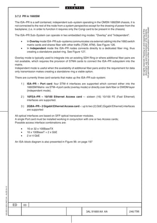
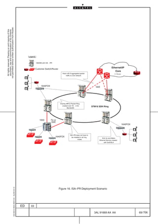
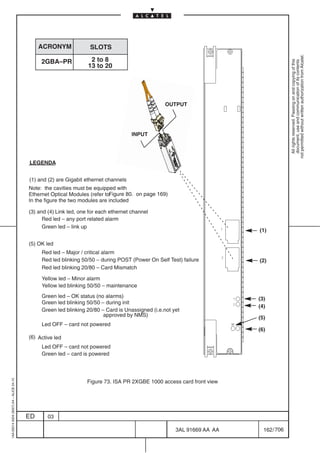
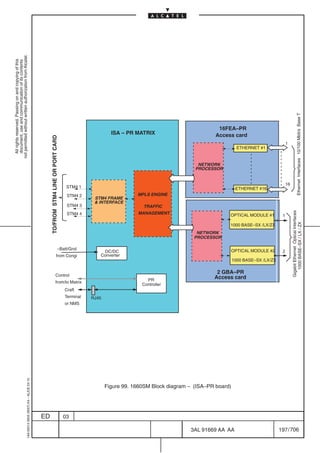
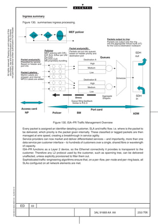
![Main functional aspects of the ISA–PR:
1660SM when equipped with ISA–PR sub–system will allow point–to–point and multipoint–to–multipoint
Metro Ethernet connections between routers or switches through SDH, as depicted Figure 16.
The Packet Ring maps Ethernet over MPLS over POS and shares the bandwidth between hundreds of
not permitted without written authorization from Alcatel.
Ethernet traffic flows according to the defined SLA.
All rights reserved. Passing on and copying of this
document, use and communication of its contents
The bandwidth in this Packet Ring may, and likely will, be oversubscribed; hence sophisticated traffic
management functions are provided to ensure the service SLAs are adhered to.
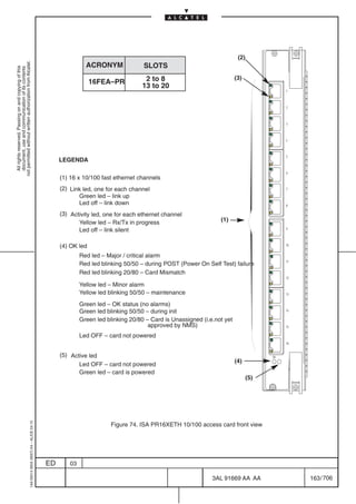
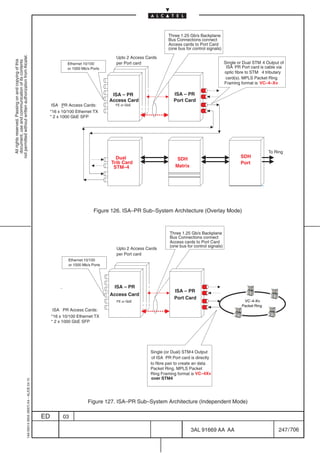
All the Ethernet access connectors are on the front panel of the 2GBA–PR and 16FEA–PR cards.
A full–blown configuration constitutes two or three cards.
An ISA–PR Port card and at least one of either an 2GBA–PR and/or 16FEA–PR Access card, which
provide various combinations of 10/100 and GbE interfaces.
ISA–PR ”Overlay” Packet Ring provides:
• Layer 1 – STM–4 (or dual STM–4)
• Layer ”1.5” – MPLS over PPP/HDLC Packet Ring multiplexed over VC–4–4v, VC–4–6v and
VC–4–8v
• Ring protection is executed at the overlay L1.5 level
• Ring operational modes: Uni–directional and [future] Bi–directional
The ISA–PR Ethernet Packet Ring bandwidth is constructed from a virtually concatenated SDH path in
the form VC–4–xv (where x=4, 6, 8). This Packet Ring provides sub–50ms protection by employing packet
wrapping to ensure restoration or traffic under ring or node failure conditions.
The ISA–PR board provides the operator with the flexibility to provision the mapping between the ISA–PR
port STM–4 interfaces and the SDH Ring; in this way the operator can choose the mapping which he thinks
more appropriate:
ISA–PR provides the following concatenation options over a single STM–4 interface:
• VC–4–4c over a single STM–4 interface
• VC–4–4v over a single STM–4 interface
ISA–PR provides the following concatenation options over dual STM–4 physical interfaces:
• VC–4–6v over two STM–4 interfaces
• VC–4–8v over two STM–4 interfaces
Ethernet frames arriving onto the ports of an 2GBA–PR and 16FEA–PR Access card are firstly classified
to determine priority and destination, placed in the appropriate priority queue and then mapped, according
to SLA rules, into the Packet Ring via the ISA–PR Port card – the mapping used is
Ethernet/MPLS/POS/SDH.
The output of the ISA–PR port card uses either two or four STM–4 optical outputs, which are connected
externally (via optical cable) into one or more 1660 SM STM–4 tributary cards toward the SDH matrix, then
through the back–Plane and finally out onto the physical SDH ring as an overlay embedded Packet Ring.
1AA 00014 0004 (9007) A4 – ALICE 04.10
ED 03
3AL 91669 AA AA 249 / 706
706](https://image.slidesharecdn.com/1660smtecr5-2ed03-100224044520-phpapp01/85/1660-S-M-Tec-R5-251-320.jpg)


![3.7.2.3 Protection sub–system
The following protection mechanisms are provided:
– native packet ring protection, refer to point [1] on page 259
not permitted without written authorization from Alcatel.
All rights reserved. Passing on and copying of this
document, use and communication of its contents
– Dual Attach, refer to point [2] on page 260.
– Customer Edge (CE) Dual Homing, refer to point [3] on page 261.
[1] Packet ring protection
The packet protection is provided by the MPLS–based Resilient Packet Ring (RPR) technology, via
“Wrapping” mechanism (see Figure 133. on page 259).
RPR is currently being standardized by the IEEE 802.17 Working Group and specifies a technology for
packet–based transport in ring topologies defining special functions that offer fast fault location and trigger
fast switchover at packet level.
RPR is used to optimize and manage the portion of bandwidth dedicated to packet traffic in SDH networks.
An RPR topology consists of two counter rotating fiber rings (or portion of SDH fiber rings bandwidth) in
which multiple nodes share the whole bandwidth (see Figure 133. on page 259)
Negotiation for bandwidth occurs among the nodes through specific fairness mechanism that guarantees
fair bandwidth allocation for customer traffic per each node. Nodes can send packets to other nodes either
by utilizing unicast (point–to–point) or multicast (multipoint) destinations, which enables multipoint
Ethernet VPN and Ethernet aggregation services be implemented over RPR.
When sending a packet, the node determines which ring direction to use, so the spans in the opposite
direction remains free for other customer traffic sent by other nodes.
A packet traveling on the ring is stripped by the destination node. This means that the packet does not use
all the ring bandwidth but only the span that it requires to go from source to destination. This features is
called “spatial reuse” as the bandwidth of the other span of the ring can be used by other paying traffic.
RPR protection protocol provides sub–50msec resilience for traffic in case of fiber or node failure.
Specific control packets are exchanged among the nodes to keep the ring constantly monitored.
“Wrapping” mechanisms is provided for packet protection switch accomplished by merging the frames
destined at the failed segment, into payload destined at the opposite direction by node adjacent to the
failed segment.
Additionally, RPR provides ring–wide QoS assurance mechanisms and three different CoS.
1660SM 1660SM
Figure 133. RPR protection mechanism
1AA 00014 0004 (9007) A4 – ALICE 04.10
ED 03
3AL 91669 AA AA 259 / 706
706](https://image.slidesharecdn.com/1660smtecr5-2ed03-100224044520-phpapp01/85/1660-S-M-Tec-R5-261-320.jpg)
![MPLS–based RPR technology.
To extend the packet protection (and end–to–end QoS...) to a multiring network, it is necessary to put
MPLS as the “upper layer” on top of RPR. MPLS provides the technology to handle traffic in multiring
networks thus ensuring end–to–end resilience and QoS for carrier–class Ethernet services across such
not permitted without written authorization from Alcatel.
a network.
All rights reserved. Passing on and copying of this
document, use and communication of its contents
In Figure 134. each ring is responsible of providing RPR protection while the MPLS upper layer working
on top of RPR guarantees end–to–end resilience and networking. This is achieved by using two
techniques:
– Martini MPLS encapsulation
– Dual attach protection (described in the following paragraph [2])
The Martini MPLS encapsulation is used to provide an end–to–end reliable support to Ethernet
networking. It specifies a technique by which Layer 2 Protocol Data Units (PDUs) such as Ethernet may
be tunneled through an MPLS enabled network. End–to–end Ethernet connectivity relations are
transported over specific MPLS Label Switched Paths (LSPs) that are switched through the network. This
allows for the provisioning of multiple, segregated customer networks over the Service Provider
infrastructure, creating a Virtual Private Network (VPN) for each customer.
1660SM 1660SM
Figure 134. Packet protection (and QoS assurance) in multiring network : MPLS over RPR
[2] Dual Attach protection
Refer to Figure 134. and Figure 23. on page 73.
The Dual Attach protection is a redundant connection to another ring or hub providing aggregate
protection.
It offers a mechanism that expands the protection capabilities of RPR to multi–ring architectures enabling
network–wide resilience.
Two RPR rings are interconnected in two points (nodes) so that networking is resilient to both node and
link failures. In addition, dual attach allows for multiple node or link failures across multiple RPR structures.
Considering Figure 134. , if either Node A fails or the link between Node A and the other ring fails, Node
B can forward packets to the other ring through its attachment keeping QoS and SLA levels unaltered.
1AA 00014 0004 (9007) A4 – ALICE 04.10
ED 03
3AL 91669 AA AA 260 / 706
706](https://image.slidesharecdn.com/1660smtecr5-2ed03-100224044520-phpapp01/85/1660-S-M-Tec-R5-262-320.jpg)
![[3] Customer Edge (CE) Dual Homing protection
The CE dual homing consists in a CE connection to two nodes in a ring for protection of the access
interfaces.
not permitted without written authorization from Alcatel.
This protection is described in the following Figure 135. and in Figure 23. on page 73
All rights reserved. Passing on and copying of this
document, use and communication of its contents
1660SM
1660SM
1660SM
1660SM 1660SM
1660SM
1660SM
Figure 135. Customer Edge Dual Homing
1AA 00014 0004 (9007) A4 – ALICE 04.10
ED 03
3AL 91669 AA AA 261 / 706
706](https://image.slidesharecdn.com/1660smtecr5-2ed03-100224044520-phpapp01/85/1660-S-M-Tec-R5-263-320.jpg)
![3.8.4 Technical specification
Latency data
not permitted without written authorization from Alcatel.
[1] GigaBit Ethernet board latency
All rights reserved. Passing on and copying of this
document, use and communication of its contents
• 1 x VC–4
– 64 bytes = 205 µs
– 512 bytes = 201 µs
– 1518 bytes = 193 µs
[2] Fast Ethernet board latency
• 1 x VC–4
– 64 bytes = 101 µs
– 512 bytes = 125 µs
– 1518 bytes = 178 µs
• 1 x VC–3
– 64 bytes = 72 µs
– 512 bytes = 147 µs
– 1518 bytes = 317 µs
• 1 x VC–12
– 64 bytes = 517 µs
– 512 bytes = 2108 µs
– 1518 bytes = 5841 µs
• 2 x VC–3
– 64 bytes = 277 µs
– 512 bytes = 1462 µs
– 1518 bytes = 3997 µs
• 8 x VC–12
– 64 bytes = 657 µs
– 512 bytes = 3452 µs
– 1518 bytes = 5824 µs
1AA 00014 0004 (9007) A4 – ALICE 04.10
ED 03
3AL 91669 AA AA 273 / 706
706](https://image.slidesharecdn.com/1660smtecr5-2ed03-100224044520-phpapp01/85/1660-S-M-Tec-R5-275-320.jpg)


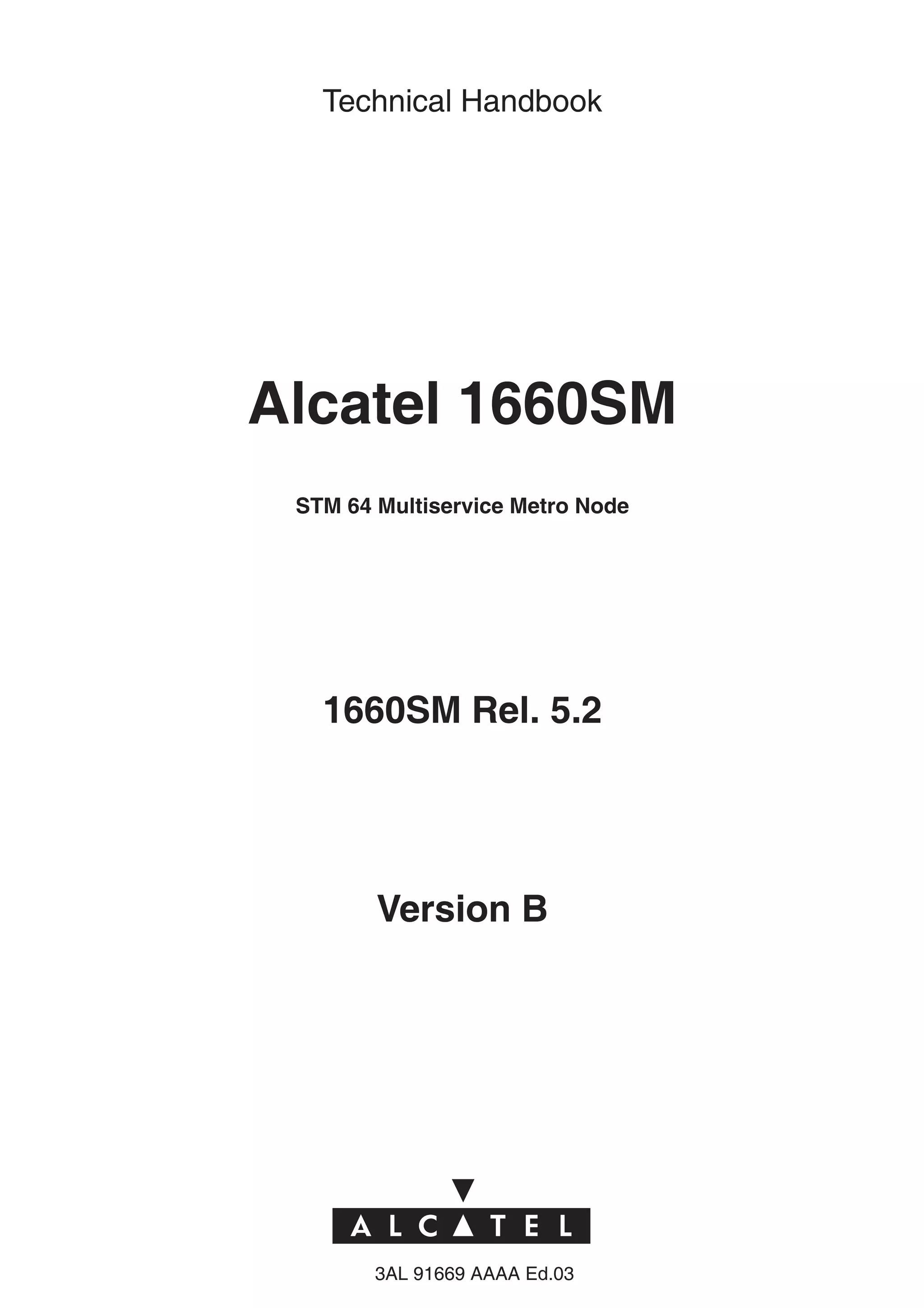
![3.8.5.2 Gbit Ethernet (rate adaptive) unit
The task of the Gigabit Ethernet functionality inside 1660SM is to carry Gigabit Ethernet packets over SDH
Virtual Containers. It can be achieved in two different ways using :
not permitted without written authorization from Alcatel.
All rights reserved. Passing on and copying of this
document, use and communication of its contents
[1] “Gigabit Access card” + “10/100 Mbit Ethernet board”: only two Gigabit interfaces are supported.
[2] “Gigabit Ethernet rate adaptive board”: up to 4 Gigabit interfaces are supported.
[1] “Gigabit Access card” + “10/100 Mbit Ethernet board”
This functionality is achieved using the 10/100 Mbit/s Ethernet board (Fast Ethernet) in conjunction with
the Gigabit Ethernet Access Card as depicted in Figure 148.
The function performed by the Access card is the interfacing on one side with the 1 Gigabit line and on
the other side with the 10/100 Mbit/s Ethernet board ( where the signal is processed) through two 1.2 Gbit/s
serial busses.
Only two of the four interfaces ( pluggable module alternatively 1000 BASE–LX , 1000 BASE–SX, 1000
BASE–ZX) on the Gigabit Access card can be used .
Gigabit interface are mapped through Generic Frame Protocol in one VC–4. with a compression ratio of
1:7; 802.3 Ethernet Flow Control is supported.
The Ethernet traffic mapped in the SDH transport structures, is then sent toward the SDH matrix through
the back–Plane which has 4 STM–1 equivalent throughput.
In the configuration depicted in Figure 148. the 10/100 Mbit Ethernet interfaces present on the
ETHERNET board can also be used taking into account the limit of the backplane.
Gigabit Eth 1
Gigabit Eth Gigabit
not used Access Card
not used 4
2 x 1.2 Gibit/s busses (through backplane)
10/100 Mbit Eth 1
10/100
ETHERNET
SDH SDH
Matrix Port
BOARD
10/100 Mbit Eth
10/100 Mbit Eth 11
Backplane : 622 Mbit/s
throughput
1AA 00014 0004 (9007) A4 – ALICE 04.10
Figure 148. Gigabit Ethernet System architecture: Gigabit access with Fast Ethernet board
ED 03
3AL 91669 AA AA 279 / 706
706](https://image.slidesharecdn.com/1660smtecr5-2ed03-100224044520-phpapp01/85/1660-S-M-Tec-R5-281-320.jpg)
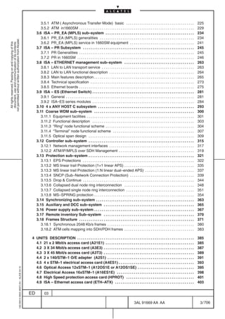
![[2] “Gigabit Ethernet rate adaptive board”
The board, named Gb Ethernet with GFP mapping (mnemonic label GETH–MB), supports up to four Gb
Ethernet interfaces in the main boards depicted in the following Figure 149.
not permitted without written authorization from Alcatel.
All rights reserved. Passing on and copying of this
document, use and communication of its contents
Ethernet Modules:
1000 Base LX
1000 Base SX
1000 Base ZX Gbit ETH
Main board
1660SM (Slot not Enhanced)
Figure 149. Gigabit Ethernet System architecture:Gigabit Ethernet main board
The Gb Ethernet interfaces (pluggable module) plugged in main board, are named Small Formfactor
Pluggable (SFP) Transceivers and they can be considered as independent items hardware, in fact they
have an own Remote Inventory. At the moment three types of Small Formfactor Pluggable Transceivers
are provided:
1. Gb Ethernet Long Haul optical interface 1000BASE–LX
2. Gb Ethernet Short Haul optical interface 1000BASE–SX
3. Gb Ethernetl optical interface 1000BASE–ZX
Each Gb Ethernet interface can be mapped through the Generic Frame Protocol (GFP) into 1, 2, 3, 4, 5,
6 or 7 VC4s. The mapping determines the rate of compression of the data throughput that can be
respectively from 1:7 to 1:1. As for the Fast Ethernet this compression is allowed thanks to the flow control
algorithm and considering the Ethernet traffic profile is typically bursty and the mean throughput is less
than the peak rate.
If the board is into an enhanced slot of 1660SM the back panel throughput is of 1.2 Gb/s instead of
622Mb/s, this determines that the maximum number of VC–4 mappable to the Gb/s Ethernet Interfaces
is 8 instead of 4. This, for example, allows the transparent (without compression) transport of a Gb
Ethernet interface into the SDH network.
In order to provide for the Gb Ethernet a rate compression less than 1/7, more than one VC4 can be used
to transport the Ethernet traffic, until a maximum of 7 VC4 where the transparent transport is obtained,
in fact 7 times 150Mb/s (VC4 payload rate) is 1050Mb/s. Note, if no compression is configured (i.e.
mapping on 7 VC4s), also another Gb/s interface can be mapped on a single VC4 (maximum compression
level), in order to use all the backpanel bandwidth (8 VC–4 equivalent).
The possibility of configuring more VC–4s, referring to the same client, is obtained by High Order virtual
1AA 00014 0004 (9007) A4 – ALICE 04.10
concatenation, where the level, the number of VC4s virtual concatenated, is provisioned by the operator.
ED 03
3AL 91669 AA AA 280 / 706
706](https://image.slidesharecdn.com/1660smtecr5-2ed03-100224044520-phpapp01/85/1660-S-M-Tec-R5-282-320.jpg)
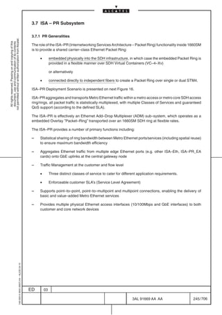
![3.9 ISA – ES (Ethernet Switch)
3.9.1 General
not permitted without written authorization from Alcatel.
All rights reserved. Passing on and copying of this
document, use and communication of its contents
Today’s evolving telecommunications services environment is highly competitive. There is a growing
demand from Enterprise customers for simple, wide–area Broadband Data services which meet their
needs for plentiful, competitively priced and flexible connectivity. Historically the success of Ethernet as
the predominate technology within the Enterprise infrastructure, has been driven by very low capital and
operational costs, the high degree of flexibility offered by the technology and importantly its easy of use
– the plug and play model. Thus enterprises are now looking for data services outside of the building (in
the WAN), which match the Ethernet technology used internally for LAN based services, without the need
for expensive conversion equipment. These new services offered by the public network in the Wide Area
are referred to a Metro Ethernet services.
Similarly network operators and service providers are looking to new services like Metro Ethernet in order
to develop new high–value revenue streams. An example of which is enhancing basic Ethernet
connectivity this through the use of value added capabilities such as Layer 2 VPNs and multiple Qualities
of Service (QoS) per connection. Deployment of Ethernet as a simplistic point–to–point technology will
only result in canalization of existing Leased Line, Frame Relay and ATM based services. Only through
the provision of Value–Added Services (VAS) of basic Ethernet connectivity to provide differentiation will
Metro Ethernet services deliver incremental revenues and ultimately profitability.
The ISA–ES series modules can deliver a full set of Ethernet services that are described in the next points
[1] to [4].
[1] Ethernet Private Line
EPLine service connects two ports of a client between each other in a transparent fashion (using
transparent mode).
Traffic originating from one Customer Port is forwarded to the other one without any filtering and
maximum level of security possible (physical segregation through different SDH infrastructure). The
service emulates an Ethernet ”wire” which actual bandwidth is determined by the SLA and by network
load. EPLine does not require MAC learning or MAC–based forwarding.
Figure 150. Ethernet Private Line service
1AA 00014 0004 (9007) A4 – ALICE 04.10
ED 03
3AL 91669 AA AA 281 / 706
706](https://image.slidesharecdn.com/1660smtecr5-2ed03-100224044520-phpapp01/85/1660-S-M-Tec-R5-283-320.jpg)
![[2] Ethernet Virtual Private Line
EVP–Line service connects two ports of a client between each other (using bridging mode).
not permitted without written authorization from Alcatel.
Traffic originating from one Customer Port is classified and forwarded accordingly to the other end.
All rights reserved. Passing on and copying of this
document, use and communication of its contents
The service emulates an Ethernet ”wire” which actual bandwidth is determined by the SLA and by
network load. Thanks to the available Eth Multiplexing Function provided by the ISA–ES series
modules, different Virtual Private Line services can be defined on the same UNI belonging to different
applications and with different QoS SLA.
EVPLine adopts MAC learning and MAC–based forwarding according to the need.
Figure 151. Ethernet Virtual Private Line service
[3] Ethernet Virtual LAN
EVP–LAN service connects two or more ports of a client between each other (using bridging mode).
Traffic originating from one Customer Port is classified and forwarded accordingly to the other end.
The service emulates an Ethernet LAN which actual bandwidth is determined by the SLA and by
network load. EVP–LAN adopts MAC learning and MAC–based forwarding with aging timeout.
1AA 00014 0004 (9007) A4 – ALICE 04.10
Figure 152. Ethernet Virtual LAN
ED 03
3AL 91669 AA AA 282 / 706
706](https://image.slidesharecdn.com/1660smtecr5-2ed03-100224044520-phpapp01/85/1660-S-M-Tec-R5-284-320.jpg)
![[4] Broadband access
In this service, a number of customers are connected to a common Aggregate Port (e.g. typically
connected to an ISP point of presence) Traffic is only delivered from individual Customer Ports to the
not permitted without written authorization from Alcatel.
Aggregate Port.
All rights reserved. Passing on and copying of this
document, use and communication of its contents
Broadband Access can distinguish between various customers’ traffic at the Aggregate Port using
VLAN tags.
For each customer that is attached to the BA service it is possible to define a specific QoS SLA.
Figure 153. Broadband Access service
1AA 00014 0004 (9007) A4 – ALICE 04.10
ED 03
3AL 91669 AA AA 283 / 706
706](https://image.slidesharecdn.com/1660smtecr5-2ed03-100224044520-phpapp01/85/1660-S-M-Tec-R5-285-320.jpg)

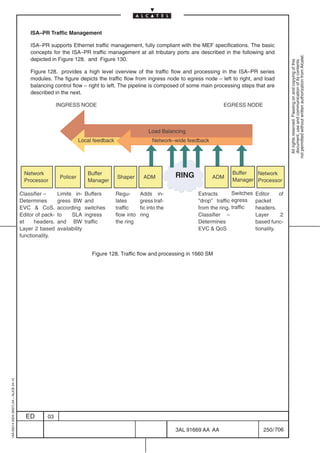
![Figure 155. provides an high level overview of the traffic flow and processing in the ISA–ES series
modules.
The pipeline is composed of five main processing steps that are described in the next paragraphs.
not permitted without written authorization from Alcatel.
All rights reserved. Passing on and copying of this
document, use and communication of its contents
De–mapping Classifier Policer Forwarding Scheduler Mapping
Encap packet frame mapping
Header PIR Ports +
De– assembly reassembly
? =
= CIR Bridge
Frame/packet
Figure 155. Traffic flow and processing in ISA–ES series
[1] Mapping
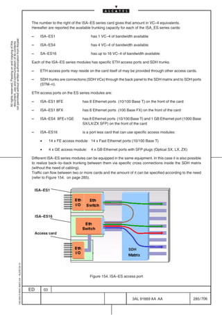
ISA–ES series modules are a family of Ethernet switching modules that provides native ETH access to
an SDH infrastructure.
Beyond just providing the physical ETH connectivity this family of modules has a full carrier class set of
functionality for optimal and efficient handling of ETH traffic flows with QoS.
An ISA–ES module receives and sends ETH traffic through two kinds of ports (refer to Figure 156. ):
• ETH physical interfaces (10/100 Base T, 100 BASE FX or 1000 Base SX/LX/ZX)
• ETH over SDH (also referred as trunk ports)
These ports are connected to a carrier class Ethernet switching engine that processes each flow and takes
care of the frame forwarding.
Eth Eth
I/O Switch
ETH Back
ETH Over SDH Panel
ports ports N x VC
Figure 156. ISA–ES series ports
1AA 00014 0004 (9007) A4 – ALICE 04.10
ED 03
3AL 91669 AA AA 286 / 706
706](https://image.slidesharecdn.com/1660smtecr5-2ed03-100224044520-phpapp01/85/1660-S-M-Tec-R5-288-320.jpg)
![[2] Traffic classification
ISA–ES series module can classify ETH traffic according to a wide set of standard specified criteria in order
to provide a feature reach set of capability.
not permitted without written authorization from Alcatel.
All rights reserved. Passing on and copying of this
document, use and communication of its contents
Each classified traffic is referred in the next paragraphs as a classified flow.
Classification criteria are the following:
• Port (Physical ETH or ETH over SDH)
• IEEE 802.1Q (VLAN tagging)
• IEEE 802.1p (ETH frame priority)
• IEEE 802.3 Source/Destination MAC address (also according to IEEE 802.1ad)
The ISA–ES16 module expands the classification criteria by means of also supporting:
• MPLS label (according to IETF Martini draft ETH over MPLS)
• IP–TOS/DSCP fields
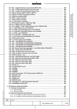
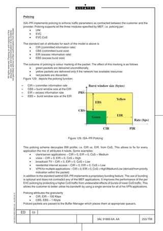
[3] Policing and metering traffic with QoS
ISA–ES series modules allow service providers and carrier operators to specify per flow traffic QoS.
ETH flows quality of service is enforced at the ingress of the network and inside the network by traffic
conformance check made by the policing function.
Policing is performed by means of a token bucket algorithm (dual rate on the ISA–ES16).
Traffic QoS is specified by a set of parameters that control its max, mean rate and the relative burst window
size in bytes.
Policing parameters are specified per classified flow according to:
CIR = committer information rate
CBS = burst window size at the CIR
PIR = excess information rate
PBS = burst window size at the PIR
Burst window size (bytes)
PBS
Yellow
EBS
CBS
EIR
Green
Rate (bps)
CIR PIR
1AA 00014 0004 (9007) A4 – ALICE 04.10
Figure 157. ISA–ES series traffic parameters
ED 03
3AL 91669 AA AA 288 / 706
706](https://image.slidesharecdn.com/1660smtecr5-2ed03-100224044520-phpapp01/85/1660-S-M-Tec-R5-290-320.jpg)
![Through the specification of per flow traffic parameters the ISA–ES series modules can support the
following SLAs:
a) Guaranteed SLA
not permitted without written authorization from Alcatel.
All rights reserved. Passing on and copying of this
document, use and communication of its contents
Typically serves High priority traffic for mission critical applications that require loss–less delivery and
minimal delay.
Guaranteed SLA denotes BW (CIR = PIR 0 in 100Kbps increments), which is always available
regardless of any congestion conditions. Traffic delivered using Guaranteed BW, is policed to the CIR
value with a burst window equal to the CBS.
Guaranteed traffic is always composed of green packets and gets the highest priority in the
processing chain.
b) Regulated SLA
Typically serves Medium priority traffic, which relies on transport layer protocol (per OSI stack) to
recover from occasional loss and requires moderate delay; e.g. client–server applications.
Regulated SLA denotes BW (PIR CIR 0 in 100Kbps increments), which may be overbooked per
network operator’s overbooking policy. The portion of bandwidth between CIR and PIR (aka EIR)
may therefore be partially available under congestion conditions. This SLA is available only from the
ISA–ES16 card.
Regulated traffic is composed of green and yellow (Excess of CIR) packets.
c) Best–Effort SLA
Typically serves Low priority traffic, which relies on transport layer protocol (per OSI stack) to recover
from loss and tolerates large delay; e.g. email and file transfer applications.
Best Effort denotes BW (PIR CIR = 0 in 100Kbps increments), which may or may not be available
per network operator’s reservation for Best Effort policy. It may therefore be unavailable under
congestion conditions.
Regulated traffic is composed of yellow packets.
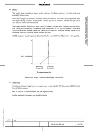
[4] Congestion avoidance and Scheduling
Congestion avoidance techniques serve to anticipate and avoid network congestion conditions wile
maximizing network utilization and good–put of the traffic flows.
Congestion avoidance in ISA–ES series modules is based on a combination of Tail Dropping and WRED
(Random Early Detection); these techniques are designed to provide preferential treatment for premium
(CIR) class traffic under congestion situations while concurrently maximizing network throughput and
capacity utilization and minimizing packet loss and delay.
a) Tail drop
Tail drop treats all traffic equally and does not differentiate between classes of service. Queues fill
during periods of congestion. When the output queue is full and tail drop is in effect, packets are
1AA 00014 0004 (9007) A4 – ALICE 04.10
dropped until the congestion is eliminated and the queue is no longer full.
ED 03
3AL 91669 AA AA 289 / 706
706](https://image.slidesharecdn.com/1660smtecr5-2ed03-100224044520-phpapp01/85/1660-S-M-Tec-R5-291-320.jpg)
![[5] Switching and forwarding
ISA–ES series modules are based onto a carrier class Ethernet switching engine with auto learning
bridges according to IEEE 802.1ad.
not permitted without written authorization from Alcatel.
All rights reserved. Passing on and copying of this
document, use and communication of its contents
This engine is either wire speed performing (all the functions are performed in hw) and highly flexible and
configurable.
On a per port basis it can be used in two modes:
Transparent mode: the engine forwards all the traffic incoming from one port to another without inspection
at the specified rate.
Bridging mode with Stacked VLAN capability: a group of configured ports (ETH phy or ETH over SDH) are
bridged together with MAC auto learning function according to IEEE 802.1ad.
Transparent Mode
Eth Back Panel
I/O N x VC–4
Bridge Mode
Figure 159. ISA–ES series operational modes
a) Multiple service per UNI port
ISA–ES series modules allow multiple services to be deployed from a single UNI Ethernet port.
Thanks to the Ethernet Multiplexing Function capability different traffics can coexist on the same port
and be differentiated between them by the classification process thus get the desired QoS per flow.
CUSTOMER
SITE B
CUSTOMER
SITE C
ETH UNI
EMF
CUSTOMER
SITE A
CUSTOMER
SITE D
1AA 00014 0004 (9007) A4 – ALICE 04.10
Figure 160. Ethernet Multiplexing Function
ED 03
3AL 91669 AA AA 291 / 706
706](https://image.slidesharecdn.com/1660smtecr5-2ed03-100224044520-phpapp01/85/1660-S-M-Tec-R5-293-320.jpg)
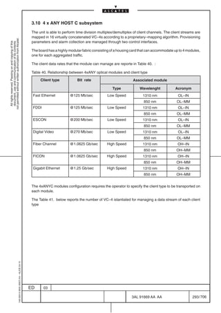
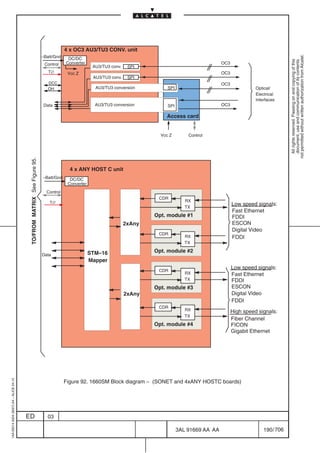
![Table 41. 4xANY HOST C client type
Client type Number of istantiated VC4
not permitted without written authorization from Alcatel.
All rights reserved. Passing on and copying of this
document, use and communication of its contents
Fiber Channel 8
FICON 8
Gigabit Ethernet 8
Digital Video 2
ESCON 2
Fast Ethernet 1
FDDI 1
The max throughput made available by the 4xANY HOSTC port is STM16 (2.5 Gb/s). The capability to
handle the whole throughput in terms of cross–connectivity depends on the equipment of the port in
“Enhanced H.S slots” rather than in “H.S. slots” of 1660SM shelf as explained on points [1] and [2].
Insertion of the board across hybrid slot (“Enhanced H.S slots” + “H.S. slots”) is not allowed.
[1] 4 x ANY inserted in enhanced slot (2526, 2829, 3435, 3738)
In ’Enhanced H.S.’ slot, the connection port –matrix can exploit two NGI links per type (i.e. 2 ’H’
/ 2 ’X’ / 2 ’L” links), each one operating at 622 Mb/s (equivalent 4xSTM1’s), with a total connection
bandwidth of 1.2 Gb/s per slot; then, the port equipped in two ’Enhanced’ slots, allows the user to
use up to 2.5 Gb/s throughput according to the client allocation grid showed in Figure 162.
1AA 00014 0004 (9007) A4 – ALICE 04.10
ED 03
3AL 91669 AA AA 294 / 706
706](https://image.slidesharecdn.com/1660smtecr5-2ed03-100224044520-phpapp01/85/1660-S-M-Tec-R5-296-320.jpg)
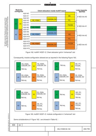
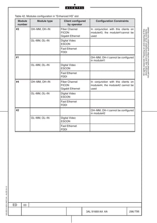
![[2] 4 x ANY inserted in not enhanced slot (3031 and 3233)
In ’H.S.’ slot, the same connectivity is based on one NGI link per type (i.e. ’H’ / ’X’ / ’L’); with a total
connection bandwidth of 622 Mb/s per slot; then, the equipment of the port in two ’H.S.’ slots, allows
not permitted without written authorization from Alcatel.
the user to use up to 1.2 Gb/s throughput. In Figure 164. , the client allocation, concerning Gb
All rights reserved. Passing on and copying of this
document, use and communication of its contents
Ethernet, Fiber Channel, FICON and the relationship with NGI links available for connecting Matrix
card, are showed.
Client allocation inside 4xANY board Links
AU–4 towards
optimization MATRIX
AU4 #0 AU4 #0 GE,
Modules AU4 #1 GE, AU4 #1 FC,
configured AU4 #2 NGI link #0
ESCON, AU4 #2 FICON
AU4 #3 FE, FDDI DV FC, AU4 #3
AU4 #4 AU4 #4 AU4’s
AU4 #5 FICON AU4 #5 not NGI link #1
#1 #3 not
AU4 #6 FE, FDDI ESCON, AU4 #6 available available
AU4 #7 DV AU4 #7
AU4 #8 ESCON, AU4 #8 GE,
#2 #4 AU4 #9 FE, FDDI DV GE, AU4 #9 FC,
NGI link #2
AU4 #10 AU4 #10 FICON
AU4 #11 FC, AU4 #11
AU4 #12 FE, FDDI ESCON, AU4 #12 AU4’s
AU4 #13 DV FICON AU4 #13 not NGI link #3
not
AU4 #14 AU4 #14 available available
AU4 #15 AU4 #15
Figure 164. Client allocation grid in “HS slots” with GE/FC/FICON
In Figure 165. , the ’optimized’ client allocation, concerning Fast Ethernet, FDDI, ESCON, Digital
Video, , and the relationship with NGI links available for connecting Matrix card, are showed.
1AA 00014 0004 (9007) A4 – ALICE 04.10
ED 03
3AL 91669 AA AA 297 / 706
706](https://image.slidesharecdn.com/1660smtecr5-2ed03-100224044520-phpapp01/85/1660-S-M-Tec-R5-299-320.jpg)
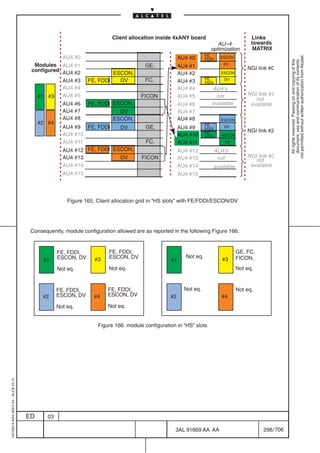
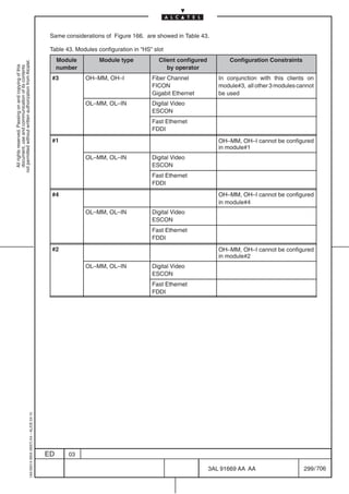
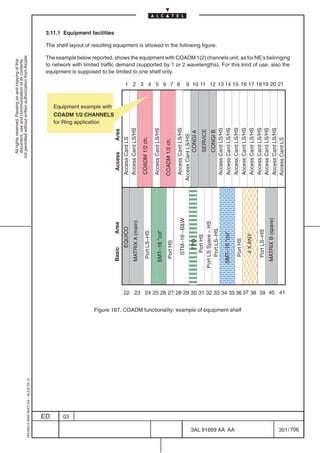
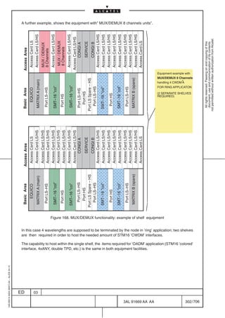
![3.11.2 Functional description
1660SM with WDM signal flow is functionally based, both in ’ring’ and ’linear’ application, on three
directions:
not permitted without written authorization from Alcatel.
All rights reserved. Passing on and copying of this
document, use and communication of its contents
1660SM 1660SM function
interfacing
Figure 169. 1660SM signal flow diagram with WDM application
[1] “client” signals groomed by SDH matrix and carried by ’CWDM’ wavelengths;
[2] “client” signals not groomed by SDH matrix and carried, transparently, by ’CWDM” wavelengths
(wavelength assignment on B/W signals);
[3] “server” signals not groomed by SDH matrix and regenerated on same or different wavelength.
1AA 00014 0004 (9007) A4 – ALICE 04.10
ED 03
3AL 91669 AA AA 303 / 706
706](https://image.slidesharecdn.com/1660smtecr5-2ed03-100224044520-phpapp01/85/1660-S-M-Tec-R5-305-320.jpg)
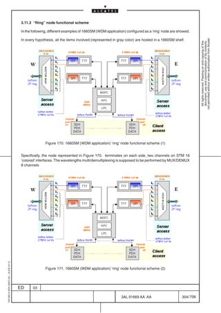
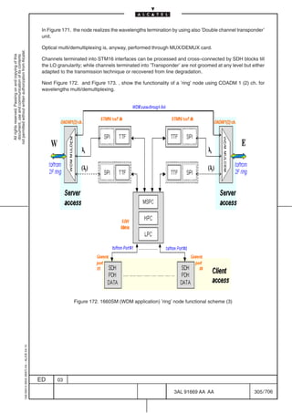
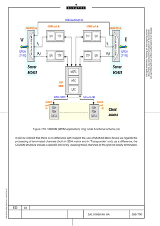
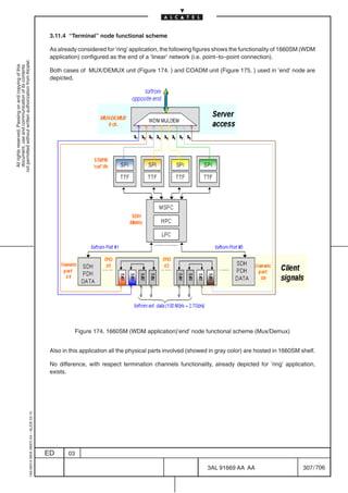
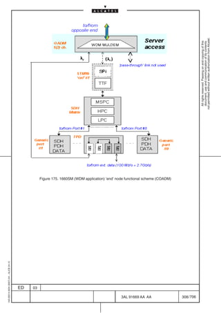
![3.11.5 Optical span design
The aim of this paragraph is defining the optical performances of 1660SM based on CWDM technology.
The optical performances definition bases on the optical characteristics related to CWDM devices
not permitted without written authorization from Alcatel.
supported by the equipment (Transceivers, Mux/Demux, OADM) and on the fiber cable characteristics
All rights reserved. Passing on and copying of this
document, use and communication of its contents
supposed.
The CWDM technology is characterized by channel spacing wider than Dense WDM and allows to realize
cost–effective applications, through a combination of un–cooled lasers (huge λ deviation versus
temperature range, e.g. 8 nm), relaxed laser wavelength selection tolerances (e.g. ± 2 nm) and wide
pass–band filters (e.g. 14 nm) inside the optical passive functions.
The following paragraphs concern:
[1] CWDM channels used
[2] the optical functions characteristics in terms of structures and insertion losses ( Mux/Demux/OADM
optical operations: structures and insertion losses);
[3] the fiber attenuation coefficient and fiber chromatic dispersion profile
[4] the transceiver optical characteristics necessary for power budget calculation
[1] CWDM channels table
The set of wavelengths used in the 1660SM equipment is a subset of the nominal central wavelengths
grid defined in the ITU–T G.694.2 Recommendation for coarse WDM systems. The complete CWDM
wavelengths grid range is from 1270 nm to 1610 nm with spacing of 20 nm. This spacing is the trade–off
between the coarse technological aspects and the need to maximize the number of channels available.
Table 44. CWDM channels grid supported by 1660SM
Nominal central wavelengths (nm)
used in the CWDM 1660SM
1470
1490
1510
1530
1550
1570
1590
1610
1AA 00014 0004 (9007) A4 – ALICE 04.10
ED 03
3AL 91669 AA AA 309 / 706
706](https://image.slidesharecdn.com/1660smtecr5-2ed03-100224044520-phpapp01/85/1660-S-M-Tec-R5-311-320.jpg)
![[2] Mux/Demux/OADM optical operations: structures and insertion losses
1660SM supports the following WDM functions:
not permitted without written authorization from Alcatel.
– multiplexing and demultiplexing of 8 CWDM channels without ’channels pass–through’ link through
All rights reserved. Passing on and copying of this
document, use and communication of its contents
COMDX8;
– multiplexing and demultiplexing of 2 CWDM channels with ’channels pass–through’ link through
COADM2;
– multiplexing and demultiplexing of 1 CWDM channel with ’channels pass–through’ link through
COADM1.
Figure 176. shows a generic application of the optical functions listed above with the definitions used in
the following paragraphs.
Table 45. shows the maximum insertion losses (dB) between:
– demux ’In’ and generic channel ’Drop’;
– generic channel ’Add’ and mux ’Out’;
– demux ’In and mux ’Out’ (’Pass–through’ connection).
Note – Channel loop insertion–loss is given by adding demux ’In’ and generic channel ’Drop’ to generic
channel ’Add’ and mux ’Out’.
Pass–through
Demux
Fiber Fiber
Mux
In Out
Loop
Drop Add
West East
Pass–through
Demux
Fiber
Mux
Out Loop In Fiber
Add Drop
Board #1 Board #2
1AA 00014 0004 (9007) A4 – ALICE 04.10
Figure 176. Passive optical operation
ED 03
3AL 91669 AA AA 310 / 706
706](https://image.slidesharecdn.com/1660smtecr5-2ed03-100224044520-phpapp01/85/1660-S-M-Tec-R5-312-320.jpg)
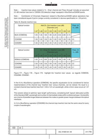
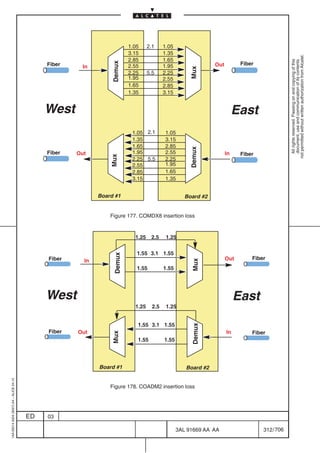
![1.05 2.1 1.05
Demux
Fiber
not permitted without written authorization from Alcatel.
Fiber In 1.25 2.5 1.25 Out
Mux
All rights reserved. Passing on and copying of this
document, use and communication of its contents
West East
1.05 2.1 1.05
Demux
Fiber Out 1.25 2.5 1.25 In
Mux Fiber
Board #1 Board #2
Figure 179. COADM1 insertion loss
[3] Fiber Technical Data
The referenced fiber for span length evaluation is the Standard Single Mode (SSMF) ITU–T G. 652.
The parameters in Table 46. and they are based on data coming from ITU–T G.957 Recommendation.
The column ’Typical Attenuation Coefficient’ includes losses due to installation splices, repair splices, and
the operating temperature range.
The column ’Maximum Attenuation Coefficient’ is obtained by considering a maximum attenuation
coefficient of about 0.3 dB/Km1. in the 1500 ÷ 580 nm and, in general, assuming a +30% tolerance over
the whole wavelength range supported by the equipment.
Table 46. Fiber technical data
Lambda Typical Attenuation Max. Attenuation Max. Chromatic Dispersion
(um) Coefficient (dB/Km) Coefficient (dB/Km) Coefficient (ps/nm/Km)
1.47 0.28 0.36 13.10
1.49 0.24 0.31 14.50
1.51 0.22 0.29 15.80
1.53 0.21 0.27 17.30
1.55 0.21 0.27 18.50
1.57 0.22 0.28 19.60
1.59 0.22 0.29 20.50
1.61 0.23 0.30 21.50
1AA 00014 0004 (9007) A4 – ALICE 04.10
1. The 0.3 dB/Km value is in compliance with the system calculation purposes indicated in the ITU–T
G.957 Recommendation.
ED 03
3AL 91669 AA AA 313 / 706
706](https://image.slidesharecdn.com/1660smtecr5-2ed03-100224044520-phpapp01/85/1660-S-M-Tec-R5-315-320.jpg)
![[4] Line transceivers and optical interface power budget (Tx–Rx)
The optical interfaces considered for power budget, span power budget and span length calculation have
the main optical characteristics showed in Table 47.
not permitted without written authorization from Alcatel.
All rights reserved. Passing on and copying of this
document, use and communication of its contents
These optical interfaces are realized through ’2R’ transceivers integrated in SFP MSA device.
Three specific devices allows to achieve the best ’performance/cost’ ratio, matching specific network
characteristics.
The two modules are:
– SFP with PIN detection, consistent with span length around 40 Km (called hereafter BRONZE
version);
– ’standard’ SFP with APD detection, consistent with span length around 70 Km (called hereafter
SILVER version);
Table 47. Optical transceiver characteristics
PARAMETER Unit Symbol BRONZE SILVER REFERENCE
Transmitter Output Optical power dBm POUT Min. 0 0
(EOL)
Typ.
Max. 5 5
Chromatic dispersion ps/ D*Km Min. 1000 1600
nm
Receiver Average Rx dBm RSENS Max. –18 –28 1
Sensitivity@OC–48+FEC
Maximum input power dBm PMAX Min. –3 –9
Optical Path Penalty dB Max. 1 2
REFERENCE:
1 – Worst–case extinction ratio (8.2dB). Measured with a PRBS 223–1 test pattern, @2.67Gb/s,
BER10–12, EOL.
1AA 00014 0004 (9007) A4 – ALICE 04.10
ED 03
3AL 91669 AA AA 314 / 706
706](https://image.slidesharecdn.com/1660smtecr5-2ed03-100224044520-phpapp01/85/1660-S-M-Tec-R5-316-320.jpg)

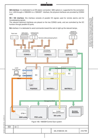

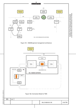
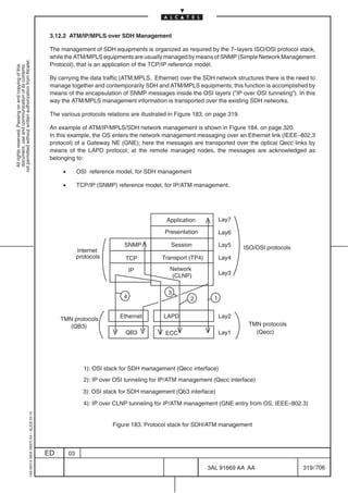
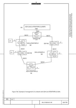
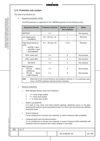
![– Collapsed single node ring interconnection
It is an architecture to connect sub–networks, in order to improve traffic availability with
hardware resource reduction (four nodes collapse in one node).
not permitted without written authorization from Alcatel.
All rights reserved. Passing on and copying of this
document, use and communication of its contents
– 2F MS–SPRING, 2 fibres Multiple Section Shared Protection
The switching information is also indicated on the Craft Terminal screen.
3.13.1 EPS Protections
[1] Matrix card protection
The positions of main and spare MATRICES are fixed :
• Slot 23 : MATRIXE main
• Slot 40 : MATRIXE spare
[2] Low Speed (LS) port protection
(See Figure 185. on page 323)
As Low Speed ports (LS) are intended the 2 Mbit/s speed ports . The Low speed port can manage up
to 63 x 2 Mbit/s port.
The LS ports are connected in a fixed way to the pertaining access cards (refer to para 2.3 on page 110)
using point–to–point connections.
To connect the 63 2 Mbit/s streams 3 access cards are needed : twenty one bidirectional links are used
for each connection between LS port and LS access card.
The spare LS port is connected with all the access cards using point–to–multipoint connections.
Only one protection group N+1 revertive can be created because the spare port card must be in a fixed
position :
• Slot 32 : spare card
The switches to select between main links and protection links are located on the access cards and
managed by a microprocessor. The switch is activated in case of failure.
Figure 185. on page 323 shows the connection between main ports, spare card and access card in case
of 63 x 2 Mbit/s port.
1AA 00014 0004 (9007) A4 – ALICE 04.10
ED 03
3AL 91669 AA AA 322 / 706
706](https://image.slidesharecdn.com/1660smtecr5-2ed03-100224044520-phpapp01/85/1660-S-M-Tec-R5-324-320.jpg)
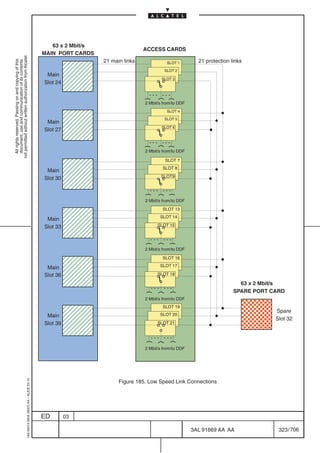
![[3] High Speed (HS) port protection
(See Figure 186. on page 324 and Figure 187. on page 326)
As High Speed ports (HS) are intended the 34 Mbit/s , 45 Mbit/s and 155 Mbit/s speed ports.
not permitted without written authorization from Alcatel.
Up to 16 HS ports can be housed in the basic area.
All rights reserved. Passing on and copying of this
document, use and communication of its contents
For the electrical HS ports the corresponding access cards have to be put in the access area with fixed
relations (refer to para 2.3 on page 110 ).
More than one protection group N+1 revertive can be created , depending on the equipment configuration.
For each group N + 1 protected group the revertive mode is supported.
The spare card position can be assigned in a flexible way . The only constraint are the following :
• the access card corresponding to the protecting card must be an HPROT card
• the HPROT card has to be plugged at the left side of the access card group
• the main/spare ports have to be adjacent.
• the protecting card has to be plugged at the left side of the protected group of ports
• the protecting/protected group of ports have to be of the same type. The only exception is for
the 3x34/3x45 port card : it can be a protecting card for both 3x34 or 3x45 port card i.e. a mixed
group of ports can be protected by the same spare card.
Figure 186. on page 324 gives some examples of EPS protection scheme.
1 2 3 4 5 6 7 8 9 10 11 12 13 14 15 16 17 18 19 20 21
ÖÖÖÖÖÁÁÁ
ÖÖ Ö Ö Á Á Á
ÖÖÁÁÁ
ÖÖÖÖÖÁÁÁ
ÖÖÖÁÁÁ ÊÊÊÔÔÔÔÔ
ÊÊ Ô Ô Ô Ô Ô
ÔÔÔÔÔ
ÔÔÔÔ
ÊÊÊÔÔÔÔÔ
ÊÔÔÔÔÔ
Ô
access card 21 x 2 Mbit/s
access card 21 x 2 Mbit/s
access card 21 x 2 Mbit/s
access card 21 x 2 Mbit/s
access card 21 x 2 Mbit/s
access card 21 x 2 Mbit/s
access card 3 x 34 Mbit/s
access card 3 x 45 Mbit/s
access card 3 x 45 Mbit/s
Access
ÖÖÖÖÖÁÁÁ
ÖÖÖÁÁÁ ÊÊÊÔÔÔÔÔ
ÊÔÔÔÔÔ
Ô
access card 4 x STM1
access card 4 x STM1
access card 4 x STM1
Area
ÖÖÖÖÖÁÁÁ
ÖÖÖÁÁÁ ÊÊÊÔÔÔÔÔ
ÊÔÔÔÔÔ
Ô
SERVICE
CONGI B
CONGI A
HPROT
HPROT
HPROT
ÖÖÖÖÖÁÁÁ
ÖÖÖÁÁÁ
ÖÖÖÖÖÁÁÁ
ÖÖÖÁÁÁ ÊÊÊÔÔÔÔÔ
ÊÔÔÔÔÔ
Ô
ÊÊÊÔÔÔÔÔ
ÊÔÔÔÔÔ
Ô
ÖÖÖÖÖÁÁÁ
ÖÖÖÁÁÁ
ÖÖÖÖÖÁÁÁ
ÖÖÖÁÁÁ ÊÊÊÔÔÔÔÔ
ÊÔÔÔÔÔ
Ô
ÊÊÊÔÔÔÔÔ
ÊÔÔÔÔÔ
Ô
ÖÖÖÖÁÁÁ
Ö Ê Ô
ÊÊÔÔ
ÖÖÖÖÖÖÁÁÁÔÊÊÊÊÔÔÔÔÔÔ
ÖÖÖÖÁÖÁÔ ÊÊÔÊÔÔÔÔ
Ö Ö Ö ÖÁ Á
ÖÁÁÁ Á ÊÔÔÔÔ
ÖÖÖÖÁÁÁÔÊÊÊÔÔ ÔÔ
ÖÖÖÖÁÁÔÊÊÊÔÔ ÔÔ
Ö ÖÁ Á Ô Ê
ÁÁÔ Ê
port 4 x STM 1 electrical
port 4 x STM 1 electrical
port 3x34 / 45 switchable
port 3x34 / 45 switchable
port 3x34 / 45 switchable
port 3x34 / 45 switchable
port 63 x 2 Mbit/s (spare)
port 4 x STM 1 electrical
port 4 x STM 1 electrical
port 4 x STM 1 electrical
ÖÖÖÖÖÁÁÔÊÊÊÔÔ ÔÔ
Ö Ö ÖÁ Á Ô Ê
Á
MATRIX B (spare)
MATRIX A (main)
port 63 x 2 Mbit/s
port 63 x 2 Mbit/s
Ö Á
ÖÖÖÖÖ
PQ2/EQC
Basic ÖÖÖÖÁÁÁÔÊÊÊÔÔ ÔÔ
ÖÖÖÖÁÁÔÊÊÊÔÔ ÔÔ
Ö ÖÁ Á Ô Ê
ÁÁÔ Ê
Area
ÖÖÖÖÖÁÁÔÊÊÊÔÔ ÔÔ
Ö Ö ÖÖ Á Ô Ê
Á
ÖÖÖÖÁÁÁÔÊÊÊÔÔ ÔÔ
Ö Ö ÖÁ Á Ô Ê
Á
Ö Á
ÖÖÖÖÖ
ÖÖÖÖÁÁÁÔÊÊÊÔÔ ÔÔ
ÖÖÖÖÁÁÔÊÊÊÔÔ ÔÔ
Ö ÖÁ Á Ô Ê
ÁÁÔ Ê
ÖÖÖÖÖÁÁÔÊÊÊÔÔ ÔÔ
Ö Ö ÖÁ Á Ô Ê
Á
Ö Á
ÖÖÖÖÖ
22 23 24 25 26 27 28 29 30 31 32 33 34 35 36 37 38 39 40 41
Figure 186. Example of EPS protection schemes
1AA 00014 0004 (9007) A4 – ALICE 04.10
ED 03
3AL 91669 AA AA 324 / 706
706](https://image.slidesharecdn.com/1660smtecr5-2ed03-100224044520-phpapp01/85/1660-S-M-Tec-R5-326-320.jpg)
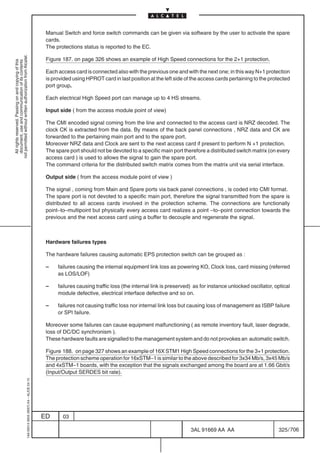
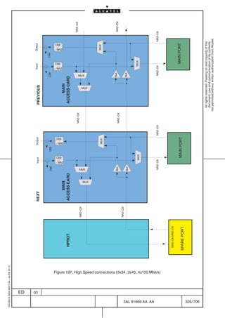
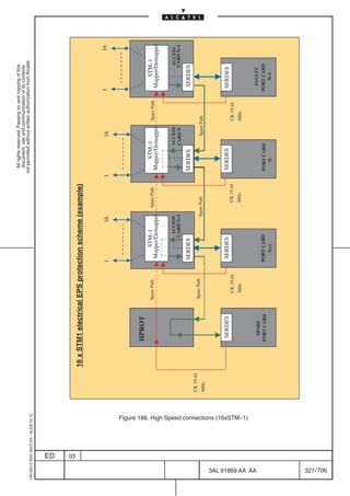
![[4] ATM MATRIX (ATM4x4, ATM4X4V2 , ATM4X4D3 and ATM8x8) protection
(see Figure 189. on page 329)
not permitted without written authorization from Alcatel.
N.B. The following description is applicable to ATM4x4, ATM4X4V2, ATM4X4D3 and ATM8x8
All rights reserved. Passing on and copying of this
document, use and communication of its contents
boards; unless otherwise specified.
The ATM MATRIX boards can be protected in 1+1 equipment protection scheme.
In this configuration the ATM MATRIX and all indirect interfaces connected to it are protected against ATM
module failure.
This does not apply to the local STM–1 interfaces of the ATM4x4 board.
In this configuration when the working ATM matrix fails the spare becomes active and the indirect
interfaces are rerouted to it.
The traffic from the local interface of the ATM4x4 board is lost.
The following ATM protection group can be created:
ATM board type Max. number of protection Mode
groups
ATM4x4 2 1+1 not revertive
ATM4x4V2 2 1+1 not revertive
ATM4x4D3 2 1+1 not revertive
ATM8x8 2 1+1 not revertive
The spare card position can be assigned in a flexible way; no restrictions for position of main and spare
ATM MATRIX board are present.
Figure 189. on page 329 gives some examples of EPS protection scheme.
The ATM MATRIX is managed by SDH EC, SC, Platform and ATM EC. In outline the management can
be divided in:
• SDH side Management: involving SDH EC, SC and Platform, it mainly applies to the Equipment
Domain of ATM MATRIX board.
In particular:
– SDH EC: management of Equipment Protection Groups and interface towards the SDH
Network Management System (e. g. creation of Protection Schemes, operator
commands, autoswitch notifications)
– SC/ Platform: management of HW
• ATM side Management: involving ATM EC, it mainly applies to the ATM Transmission Domain
of ATM MATRIX board.
Figure 190. on page 330 represent the messages exchanged between the EC (on the PQ2/EQC board)
and the ATM MATRIX boards in protection group.
1AA 00014 0004 (9007) A4 – ALICE 04.10
ED 03
3AL 91669 AA AA 328 / 706
706](https://image.slidesharecdn.com/1660smtecr5-2ed03-100224044520-phpapp01/85/1660-S-M-Tec-R5-330-320.jpg)
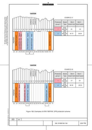
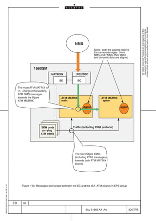
![[5] MPLS (PR_EA) ports protection
(see Figure 191. on page 332)
not permitted without written authorization from Alcatel.
The MPLS boards (PR_EA MATRIX 4xETHERNET, PR_EA MATRIX 1xGIGABIT ETHERNET) can be
All rights reserved. Passing on and copying of this
document, use and communication of its contents
protected in 1+1 equipment protection scheme (EPS) against board failure.
The 1+1 EPS cannot be applied to the local interfaces (4xethernet, gigabit ethernet). In case of failure the
traffic carried by the ethernet local ports will be lost.
In this configuration when the working PR_EA Matrix...board fails the spare becomes active and the
indirect interfaces are rerouted to it.
The traffic from the ethernet local interface is lost.
Only one protection group 1+1 not revertive can be created, depending on the equipment configuration.
The spare card position can be assigned in a flexible way; no restrictions for position of main and spare
PR_EA boards are present.
The 1+1 EPS protection scheme of PR_EA boards is the same of ATM boards one.
Figure 191. on page 332 gives some examples of EPS protection scheme.
The PR_EA EPS is managed by SDH EC, SC, Platform and PR_EA EC. In outline the management can
be divided in:
• SDH side Management: involving SDH EC, SC and Platform, it mainly applies to the Equipment
Domain of the PR_EA... board.
In particular:
– SDH EC: management of Equipment Protection Groups and interface towards the SDH
Network Management System (e. g. creation of Protection Schemes, operator
commands, autoswitch notifications)
– SC/ Platform: management of HW
• MPLS side Management: involving PR_EA... EC, it mainly applies to the MPLS Transmission
Domain of the PR_EA... board.
Figure 192. on page 333 represents the messages exchanged between the EC (on the PQ2/EQC board)
and the PR_EA Matrix... boards in protection group.
1AA 00014 0004 (9007) A4 – ALICE 04.10
ED 03
3AL 91669 AA AA 331 / 706
706](https://image.slidesharecdn.com/1660smtecr5-2ed03-100224044520-phpapp01/85/1660-S-M-Tec-R5-333-320.jpg)
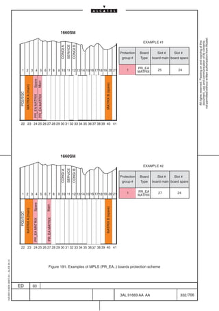
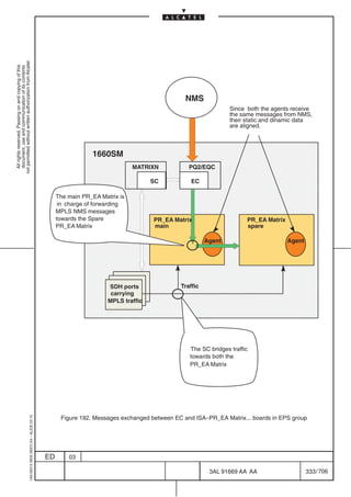
![[6] ISA ES–16 ports protection
ISA ES–16 board supports the EPS protection scheme as well as ISA ATM and ISA PR_EA boards.
not permitted without written authorization from Alcatel.
The EPS protection scheme is 1+1, where the main and spare positions are assigned by
All rights reserved. Passing on and copying of this
document, use and communication of its contents
managementsystem in a flexible way (Note).
Note: The board main and the board spare have to be configured on throughput equivalent slot (i.e. both
not enhanced slots or both enhanced slots).
The characteristics of the protection scheme: the switching type is unidirectional (single–ended), the
operation type is Not Revertive (this means that WTR time is not applicable), the external commands are:
Manual Switch working, Manual Switch spare, and Clear. The command Lockout of spare is not provided,
as well Force switch working and Force Switch spare.
The access cards (Fast Ethernet and Gigabit Ethernet) are not protected by the EPS protection scheme,
this means if the board switches the Ethernet traffic carried by the local physical interfaces is lost, unless
a protection scheme is configured on the client side like dual attach protocol for the Gigabit Ethernet
interfaces.
1AA 00014 0004 (9007) A4 – ALICE 04.10
ED 03
3AL 91669 AA AA 334 / 706
706](https://image.slidesharecdn.com/1660smtecr5-2ed03-100224044520-phpapp01/85/1660-S-M-Tec-R5-336-320.jpg)
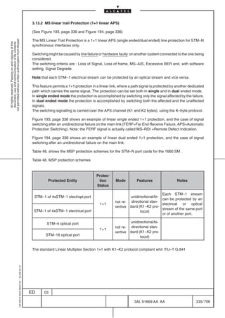
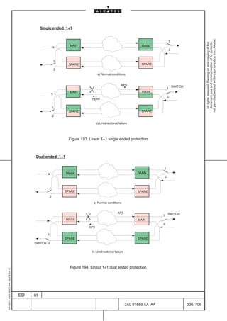
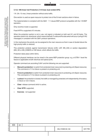
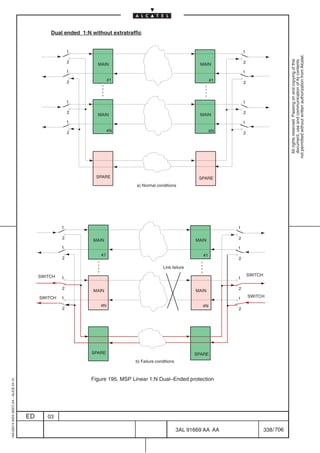
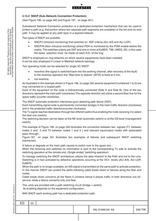
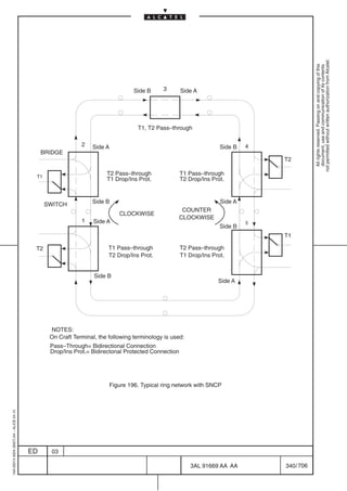
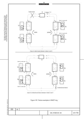
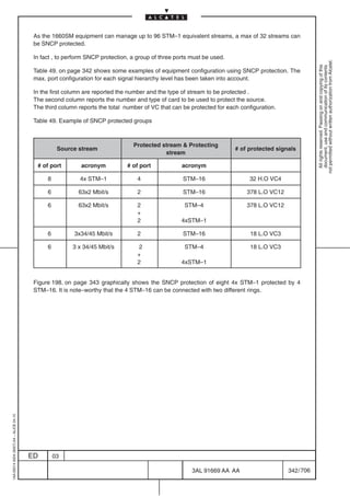
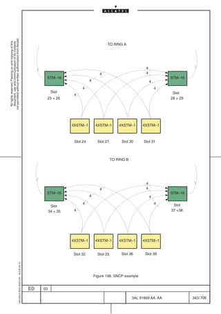

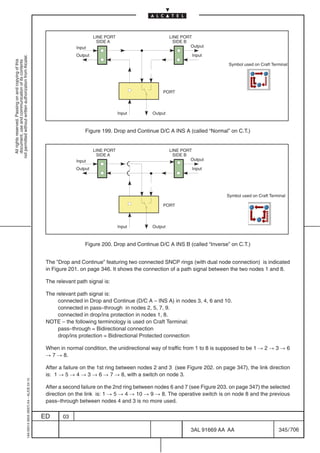
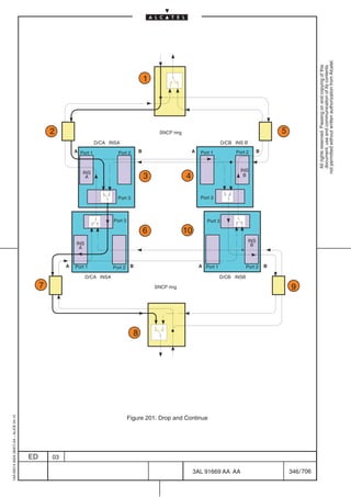
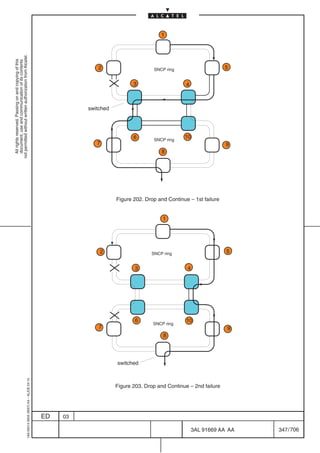
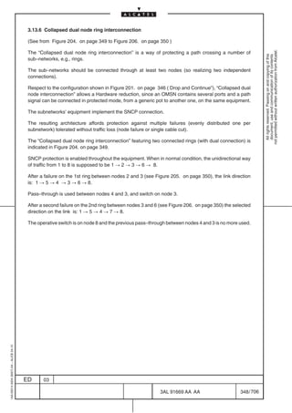
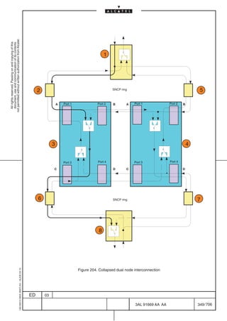
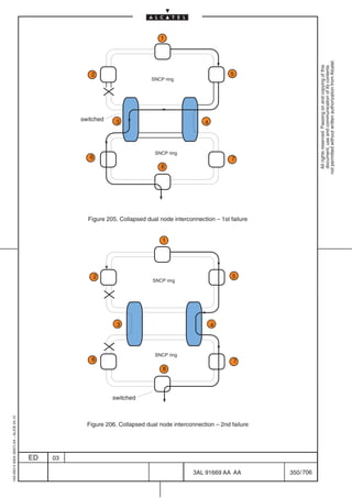
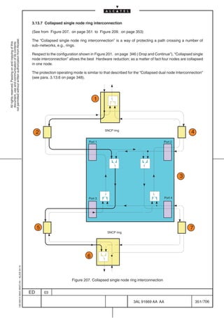
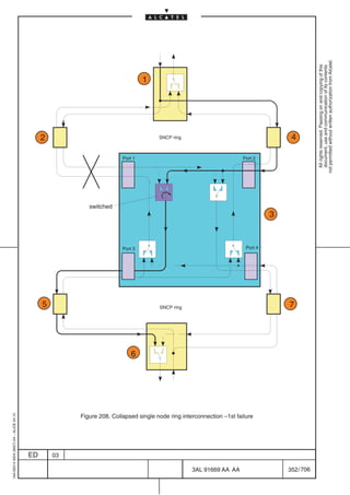
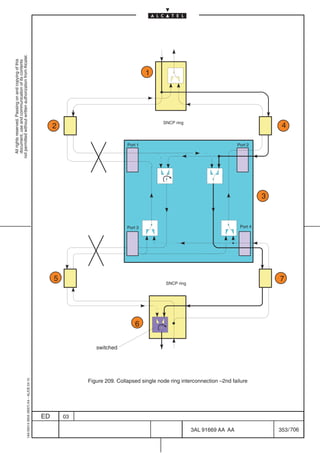
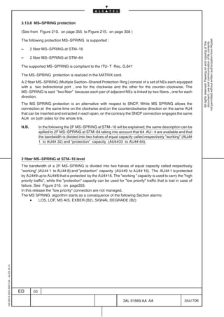
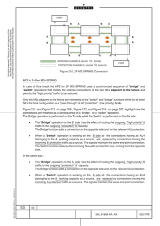
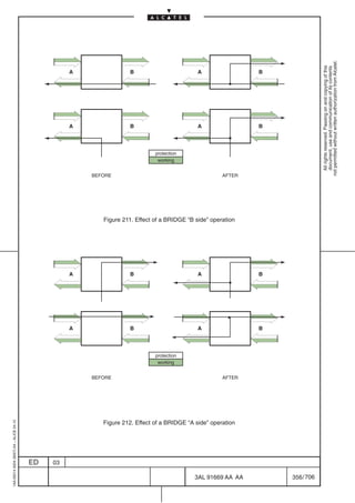
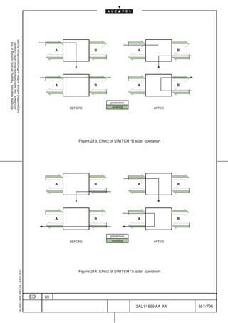
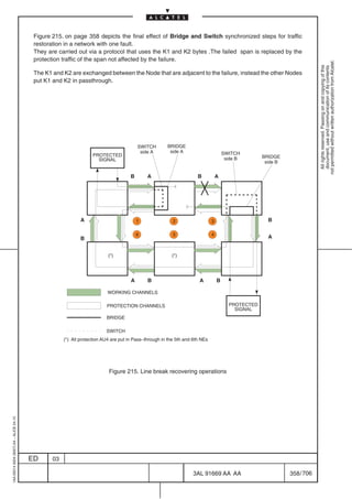

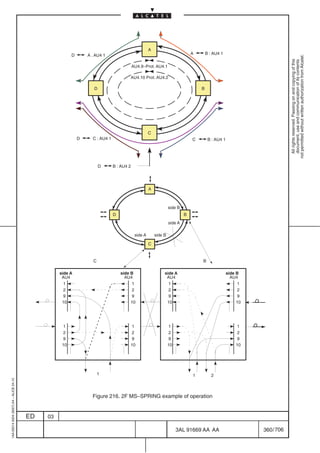
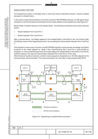
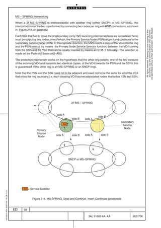
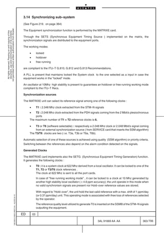
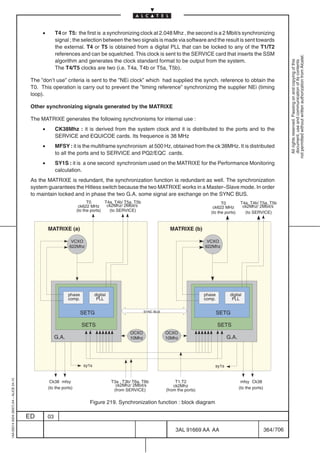
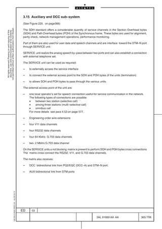
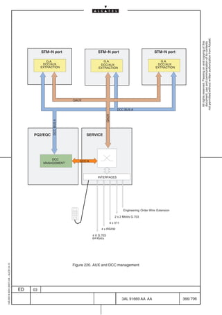


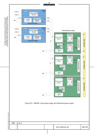
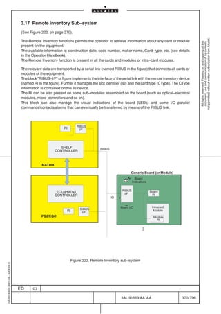
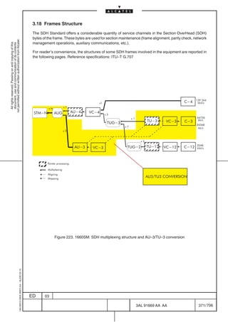
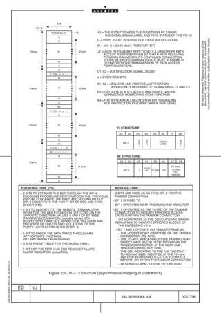
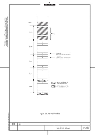
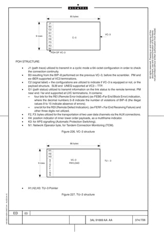
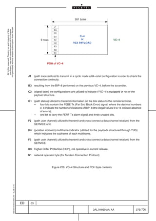
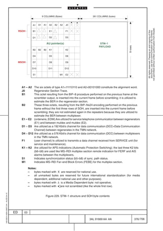
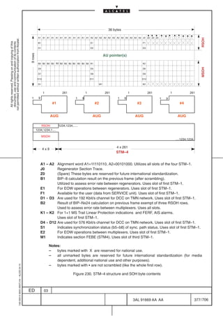
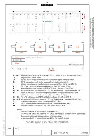
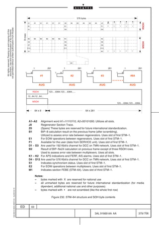
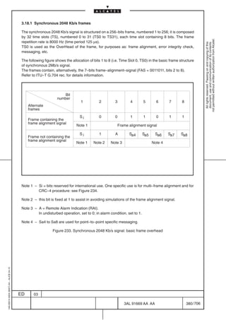
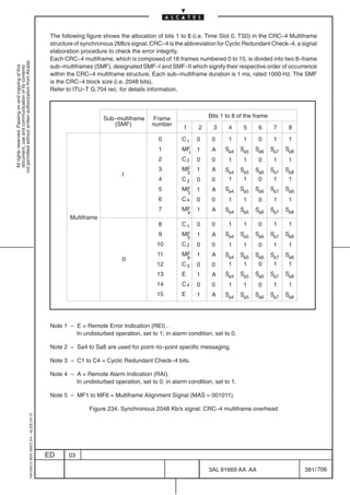
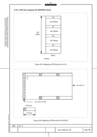
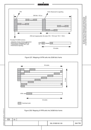

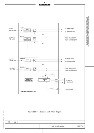
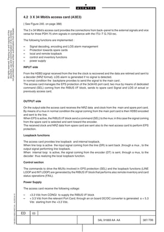
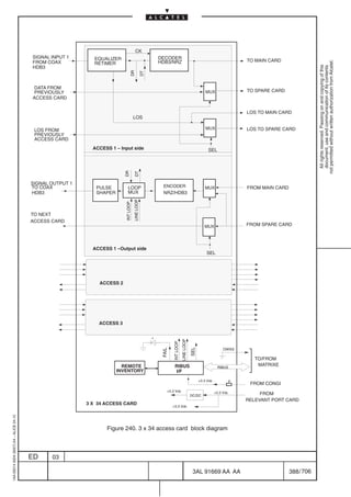
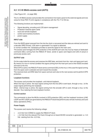
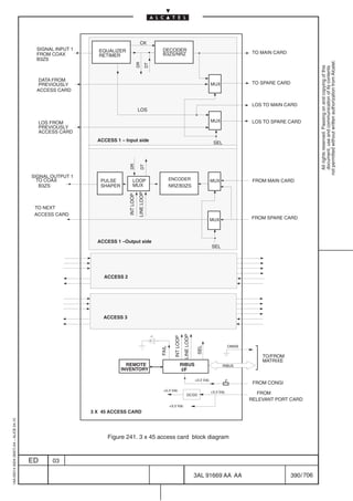
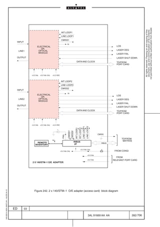
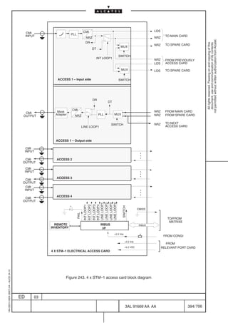
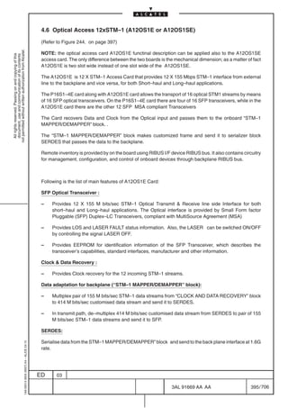

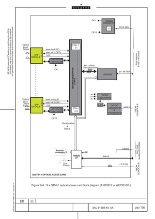
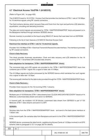

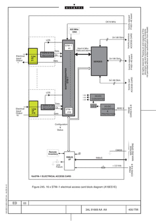

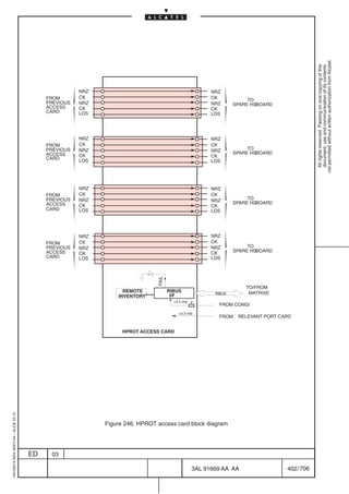
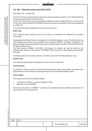
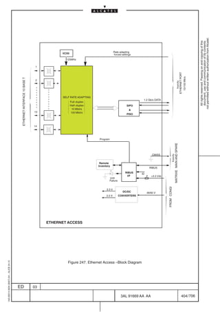
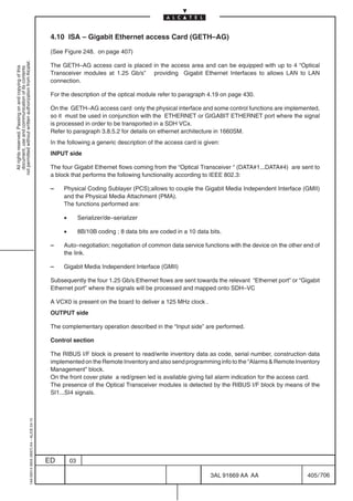

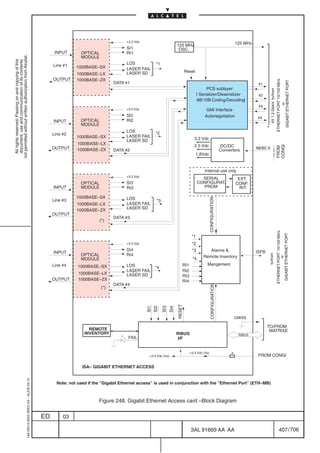
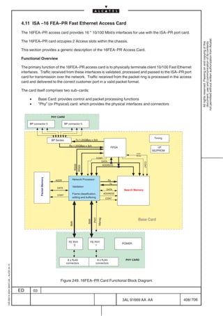
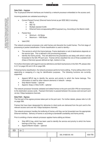
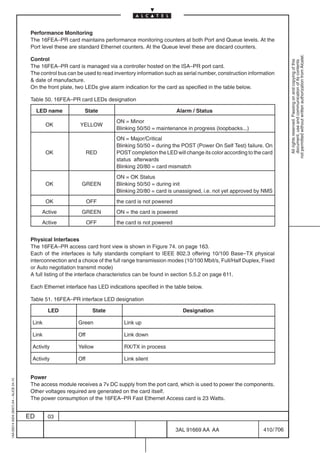
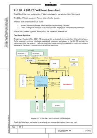


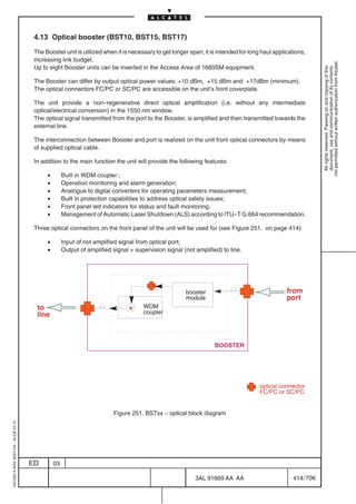


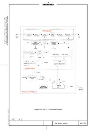

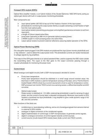
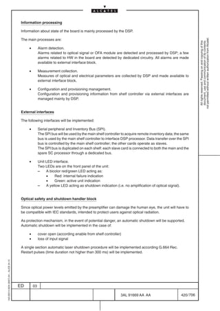
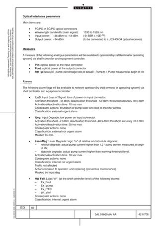

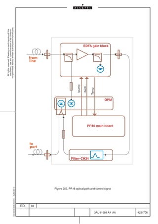
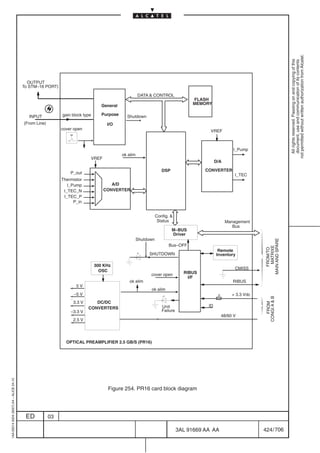
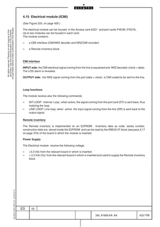
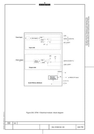
![4.16 STM–1 optical modules
(See Figure 256. on page 427)
not permitted without written authorization from Alcatel.
The STM–1 optical modules are the optical physical accesses for the STM–1 card. Different optical
All rights reserved. Passing on and copying of this
document, use and communication of its contents
modules are available according to the connector type used (FC/PC, SC/PC or LC), wave length ( IS–1.1,
L–1.1, L–1.2, L–1.2JE) and source type [Single–Mode and Multi–Mode (MM1)]. For details on Optical
Characteristics refer to Table 66. on page 628)
Input side : the optical signal is converted in an electrical signal and level adapted to be sent to the port
card (data + clock); on the receive side a LOS alarm can be detected.
Output side : the electrical signal coming from the port card (data + clock) is level adapted, converted
in an optical signal and sent to the line . The Tx optical module send and receive also the following signals:
– LASER FAIL
– LASER DEGRADE
– LASER SHUTDOWN
Remote inventory
The Remote inventory is implemented on an E2PROM . Inventory data as code, series number,
construction date are stored inside the E2PROM and can be read by the RIBUS I/F block (see para.3.17
on page 370) of the board in which the module is inserted.
Power Supply
The Electrical module receive the following voltage:
– +3.3 Vdc from the relevant board in which is inserted
– + 3.3 Vdc (Vs) from the relevant board in which is inserted and used to supply the Remote Inventory
block
EDR
OPTICAL LEVEL DATA+CLOCK RX
STM–1
INPUT INPUT ECKR ADAPTER
OPTICAL
MODULE
LOS
OPTICAL EDT
OUTPUT ECT LEVEL DATA +CLOCK TX
STM–1 ADAPTER
OUTPUT
OPTICAL LASER FAIL
MODULE
LASER DEGRADE
LASER SHUTDOWN
Laser Restart Remote RI to RIBUS I/F bus
Inventory
+3.3 Vdc (Vs)
+3.3 Vdc
STM–1 CMISSn
1AA 00014 0004 (9007) A4 – ALICE 04.10
OPTICAL MODULE
Figure 256. STM–1 Optical module – block diagram
ED 03
3AL 91669 AA AA 427 / 706
706](https://image.slidesharecdn.com/1660smtecr5-2ed03-100224044520-phpapp01/85/1660-S-M-Tec-R5-429-320.jpg)
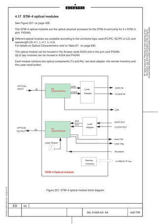


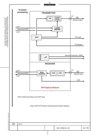
![4.20 63 x 2 Mbit/s port card (P63E1)
(See Figure 259. on page 434)
not permitted without written authorization from Alcatel.
The P63E1 is a bidirectional unit which interfaces 63 plesiochronous 2048 kbit/s signals and the
All rights reserved. Passing on and copying of this
document, use and communication of its contents
STM4–BPF signal (BPF=backpanel format).
Due to the backpanel format (STM4–BPF or STM4*), the 63 plesiochronous 2 Mbit/s signals that can be
housed in an STM–1 frame, are dropped / inserted in the AU4#1 of the STM–4* frame.
The unit is composed by the following blocks:
– (G.A.)
G.A. is an ASIC (or Gate Array) that maps 63 2Mbit/s streams into an STM–1 frame as required by
ITU–T G.783 Rec.
As the backpanel format for data exchange between 63 x 2 Mbit/s and Matrix card is STM–4*, the
2 Mbit/s streams are inserted/extracted on the AU4 #1 of the STM–4* frame.
INPUT side
• PPI (E12_TT_Sk and E12/P12x_A_Sk): This block provides the electrical interface between
the physical transmission medium and the internal unit format. The received 2048 kb/s line
signal is HDB3 coded. A decoder on the physical interface decodes the signal to NRZ (non
return–to–zero) format.
• LPA (S12/P12x_A_So) : This block adapts user data for transport in the synchronous
domain. For asynchronous user data, lower order path adaptation involves bit justification. The
2.048 Mbit/s is inserted into a C–12 container (by means of asynchronous mapping), which is
synchronized (stuffing) with the correspondent TU–12.
• V5[5–7]: Signal label insertion in the byte V5[5–7].
• LPT (S12_TT_So) : The LPT function creates a VC–12 by generating and adding POH to a
C–12. The POH formats are defined in Recommendations G.708 and G.709.
• J2: trail trace identifier is generated.
• V5[1,2]: BIP–2 is calculated and transmitted.
• V5[3]: the number of errors is encoded in REI.
• V5[8]: RDI indication is inserted.
• LTCT So : This block performs Tandem Connection Termination and Adaptation Source
functions, according to ITU and ETSI standards, on Low Path tributaries. It inserts into incoming
Low order VC the N2 byte, and performs BIP–2 parity compensation for that byte insertion. The
inserted N2 is composed by remote signalling, incoming error count, APId.
• STM4–BPF I/F () :
The STM–1 equivalent signal is multiplexed into the Back–Panel STM4* equivalent signal.
The signal is sent to the ”Main” and ”Spare” MATRIX cards .
OUTPUT side
• EPS :
This block select one of the two signal source provided by the MATRIX cards ”Main” and ”Spare”
• STM4–BPF I/F () :
1AA 00014 0004 (9007) A4 – ALICE 04.10
The STM–1 equivalent signal is demultiplexed from the Back–Panel STM4* equivalent signal.
ED 03
3AL 91669 AA AA 432 / 706
706](https://image.slidesharecdn.com/1660smtecr5-2ed03-100224044520-phpapp01/85/1660-S-M-Tec-R5-434-320.jpg)
![• LTCT Sk : This block performs Tandem Connection Monitoring / Termination and
Adaptation Sink functions, according to ITU and ETSI standards, on Low Path tributaries
(configuration choice between Monitoring and Termination is by preset). It extracts from
incoming Low order VC the BIP–2 parity and N2 byte, and then operates alignment, detection
not permitted without written authorization from Alcatel.
and correlation of alarms, error check. When Termination function is configured, it also modifies
All rights reserved. Passing on and copying of this
document, use and communication of its contents
data flow by N2 byte overriding, AIS insertion, generation of remote signalling.
• LPT (S12_TT_Sk): The LPT function terminates and processes the POH to determine the
status of the defined path attributes.
• J2: trail trace identifier is recovered –– TIM detection.
• V5[1,2]: BIP–2 is recovered –– Ex–BER, Signal Degrade alarm
• V5[3]: REI bit is recovered and the derived performance primitives is reported.
• V5[8]: RDI information is recovered and reported.
• AIS or SSF detection –– SSF alarm
• LPA (S12/P12x_A_Sk): It extracts the VC12–POH and processes the TU12 pointer.
• V5[5–7]: Signal label detection in the byte V5[5–7] –– Signal label Mismatch
detection
• AIS or SSF is applied if Signal label Mismatch is detected
• PPI (E12/P12x_A_So and E12_TT_So):This block provides the interface between the
internal unit format and the physical transmission medium. It encodes into HDB3 code the signal
to be sent on line.
Other functions implemented are :
• Clock Reference Selection Block (on G.A): provides six 2 MHz clock links towards the
MATRIX cards for synchronization purposes. The selection among the 63 flows is made via
software.
• TIMING (on G.A): receives the reference clock (38.88 MHz) and synchronism pulse (500 Hz)
from the MATRIX cards and extracts the local clocks used by the G.A.
The Tx clock is locked, by means of a PLL to the system clock or, when in free running, to a local
oscillator with a +–50ppm drift: (51 MHz OSC) block.
• RIBUS I/F
This block is used to read/write from/to the ”RIBUS” stream, to control the LED on the unit, to
release the Management–bus in case of power failure, and to use the remote inventory. It is
powered by the + 3.3 Vdc supply by CONGI boards.
• REMOTE INVENTORY
It is the memory containing the board information, for identification purposes (see para. 3.17
on page 370 for details).
• M–BUS Driver
It drives the input–output gates of the Management–bus. These drivers can be disabled (by
the Bus–OFF signal) in case of power failure.
• DC/DC CONVERTER
It converts the 48/60 V power supply to the 3.3 V used to supply all the components in the board.
The DC/DC converter is synchronized with a synchronization clock at 288 MHz (signal
Power–Sync, generated by G.A.) in order to avoid EMI problems.
1AA 00014 0004 (9007) A4 – ALICE 04.10
• STEP DOWN
It uses the 3.3 V power supply from DC/DC Converter block to obtain the 2.5 V used to power
the Gate Array (G.A.).
ED 03
3AL 91669 AA AA 433 / 706
706](https://image.slidesharecdn.com/1660smtecr5-2ed03-100224044520-phpapp01/85/1660-S-M-Tec-R5-435-320.jpg)
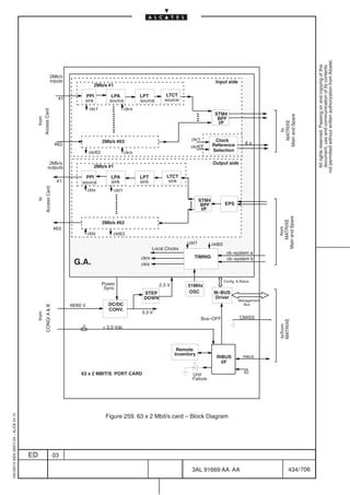
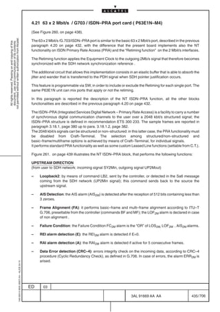
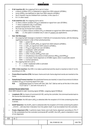

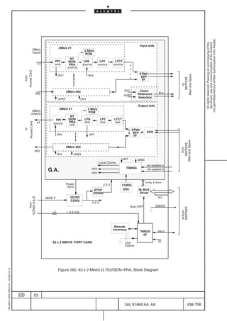
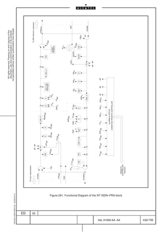

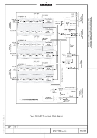
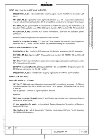

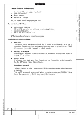
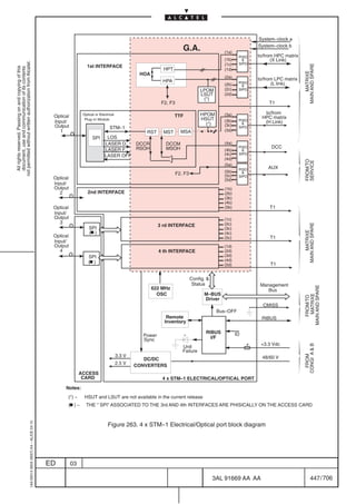
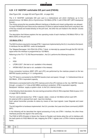
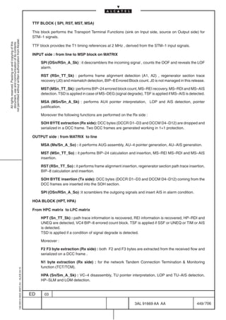
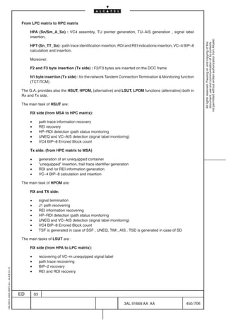
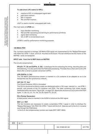

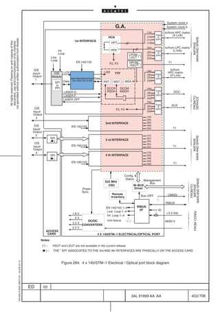
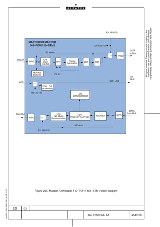
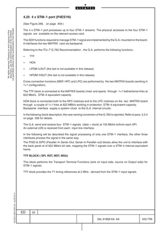
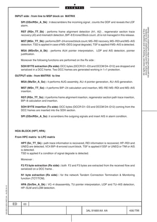
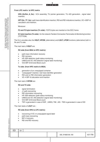

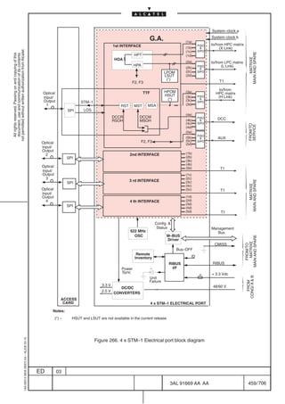
![4.26 Port 16xSTM1 – 4xSTM4 (P16S1–4E)
(Refer to Figure 267. on page 462)
not permitted without written authorization from Alcatel.
General
All rights reserved. Passing on and copying of this
document, use and communication of its contents
The board P16S1–4E provides either 4 STM–4 optical interfaces or 16 STM–1 Optical/Electrical interfaces
(along with the Optical/Electrical Access Board) (refer to Figure 91. on page 189).
The P16S1–4E board along with A12OS1E Optical Access board allows the transport of 16 optical STM1
streams by means of 16 SFP optical transceivers.
On the P16S1–4E there are four of 16 SFP transceivers, while in the A12OS1E card there are the other
12 transceivers.
On the P16S1–4E board the SFP transceivers can work at both the bit rate of 155 and 622 Mb/s for both
Short Haul and Long Haul applications.
The P16S1–4E board along with the A16ES1E Electrical Access card allows the transport of 16 electrical
STM–1 streams. All the 16 electrical line interface devices are present in the A16ES1E board.
Description
The main features of P16S1–4E board are:
[1] Provides four SFP transceivers for optical interface as per ITU–T G.957.
The Small Form–factor Pluggable (SFP) fiber optic Transceiver is used to interface the P16S1–4E
board to single mode fiber optic cables.
The SFP is hot pluggable and compliant with Multi–Source Agreement (MSA). The cage and the
connector will be mounted on the board, and the optical module will be plugged into it. There are four
SFP modules present on the P16S1–4E board, which provide optical interface to either four STM–1
or four STM–4 tributaries.
The SFPs take in optical data and give electrical signals to the “DATA CLOCK RECOVERY” block.
The SFP module is interfaced with the “MAPPER/DEMAPPER STM–1/STM–4”; The interface
consists of control and alarm signals namely LASER FAULT, LASER OFF, LOS.
[2] Provides four devices for Clock and Data recovery. Data and clock are then sent to
“MAPPER/DEMAPPER STM–1/STM–4” block.
[3] Provides a “MAPPER/DEMAPPER STM–1/STM–4” which interfaces the on–board clock and data
streams and those obtained from the Access cards at 1.6 Gb/s via “SERDES” block to the overhead
termination ”TTF+HOA” and vice versa.
[4] Provides four ”TTF+HOA” blocks, which perform trail termination sourcing/sinking functions, and
adaptation functions for sixteen STM–1/ four STM–4 streams. ”TTF+HOA” blocks also inserts and
extracts the DCC and AUX channels from the payload. These are given to/from the backplane
through the “DCC MANAGEMENT” block.
For details information about TTF and HOA block refer to the PAES1N board description on
paragraph 4.25 page 455.
[5] Provides three blocks so as to:
• Process data from/to the on board ”TTF+HOA” blocks to/from NGI interface at the back plane
1AA 00014 0004 (9007) A4 – ALICE 04.10
towards Matrix A and B at 2.5Gbps rate (DATA BACK PLANE INTERFACE ).
• Process data from /to the Access Cards at 1.6Gbps rate (SERDES).
ED 03
3AL 91669 AA AA 460 / 706
706](https://image.slidesharecdn.com/1660smtecr5-2ed03-100224044520-phpapp01/85/1660-S-M-Tec-R5-462-320.jpg)
![[6] Provides RIBUS device for power up status/configuration. Also, generation and monitoring of various
status and control signals are done through the ports of RIBUS.
[7] Provides device to control and configure the two “DATA BACK PLANE INTERFACE” blocks through
not permitted without written authorization from Alcatel.
the SPI bus and process DCC and AUX channels at the backplane.
All rights reserved. Passing on and copying of this
document, use and communication of its contents
[8] Provide EEPROM for storing the configuration data.
[9] Generates all the required voltages of 3.3V, 2.5V, 1.8V, 1.5V and 1.2V and provides circuitry for
monitoring these voltages.
[10] Provides timing circuitry, which includes 622 MHz VCXO and associated circuits for external clock
generation and PLL function.
[11] Provides one bicolour LED and a laser restart switch (the last drives both the optical interfaces on
board and on access card)
Other functions implemented are :
• RIBUS I/F
This block is used to read/write from/to the ”RIBUS” stream, to control the LED on the unit, to
release the Management–bus in case of power failure, and to use the remote inventory. RIBUS
I/F is powered by the + 3.3 Vdc supply by CONGI boards.
• REMOTE INVENTORY
It is the memory containing the board information, for identification purposes (see para. 3.17
on page 370 for details).
1AA 00014 0004 (9007) A4 – ALICE 04.10
ED 03
3AL 91669 AA AA 461 / 706
706](https://image.slidesharecdn.com/1660smtecr5-2ed03-100224044520-phpapp01/85/1660-S-M-Tec-R5-463-320.jpg)
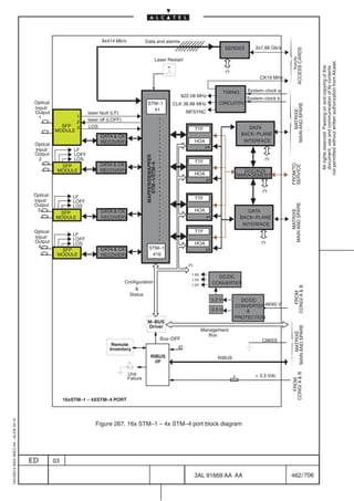
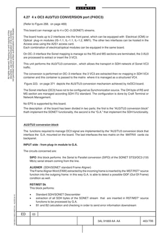
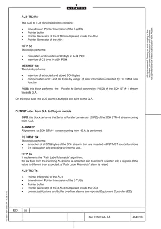
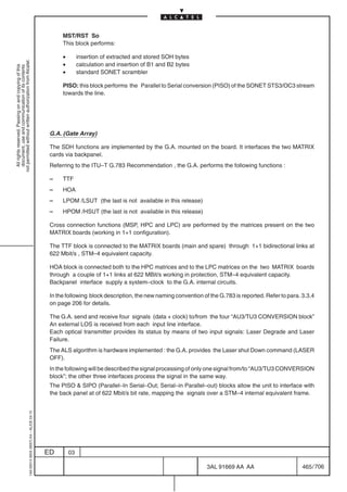
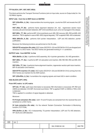


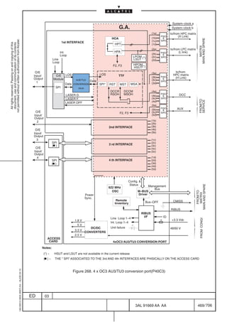
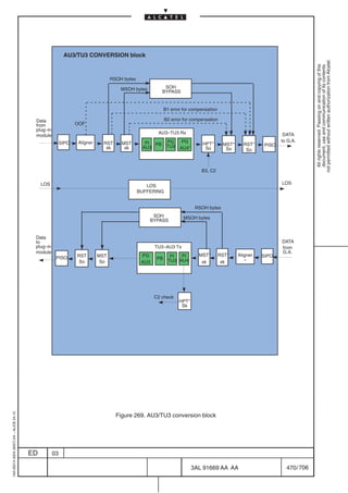
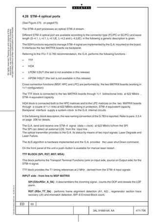
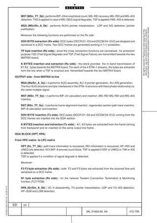

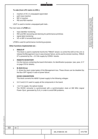
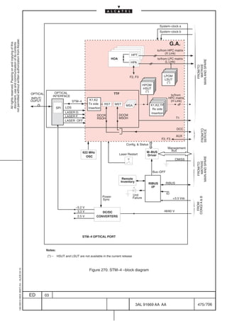
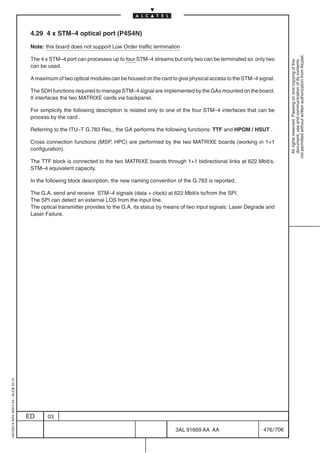
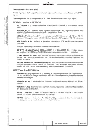

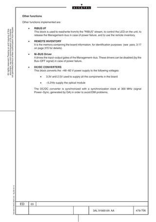
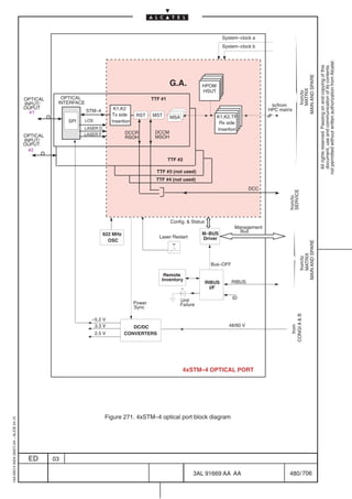
![4.30 ISA – ATM MATRIX 4X4 (ATM4X4)
(See Figure 272. on page 487)
not permitted without written authorization from Alcatel.
This unit realize an ATM switching matrix with a total bandwidth of 622Mbit/s.
All rights reserved. Passing on and copying of this
document, use and communication of its contents
The board is able to manage up to 16 LT where LT is a physical or logical channel where is mapped an
ATM flow (E1, E3, VC12, VC3, VC4).
On the board a local STM–1 access carrying an unstructured VC4 is managed.
The card perform the following functions:
[1] SDH signal processing
[2] ATM signal processing
[3] MATRIX
[4] MICROPROCESSOR
[5] Common part
[1] SDH signal processing
One STM–1 interface is available on the card. The stream can be optical or electrical according to the
modules available (electrical–STM1 or optical–STM1) inserted into the front cover cavity of the ATM
MATRIX 4X4.
The proprietary function of ”Bidirectional working on single fiber” is provided, by presetting. This function
uses the BMD (bad media dependent) byte. The BMD alarm is considered as an external LOS.
The ALS algorithm is provided by hardware implementation (Laser–Shut–Down command).
The line–interface (SPI) is performed by the pluggable module (line–module).
LOS, Laser–Degrade, Laser–fail alarms and Laser–Shut–Down commands are comprised in the
AlarmsCommands group in the figure.
The SDH functions required to manage STM–1 signals are:
– SPI, RST, MST, MSA
– HPT, LPT and LPA.
– SOH bytes
Cross connection functions (MSP, HPC and LPC) are performed by the matrices present on the two
MATRIXE board (working in 1+1 configuration).
The MSA block is connected to the MATRIXE boards (main and spare) through 1+1 bidirectional links
at 622 Mbit/s , STM–4 equivalent capacity.
SPI, RST, MST, MSA BLOCK
These blocks performs the Transport Terminal Functions (sink on Rx side, source on Tx side) for STM–1
signals.
1AA 00014 0004 (9007) A4 – ALICE 04.10
ED 03
3AL 91669 AA AA 481 / 706
706](https://image.slidesharecdn.com/1660smtecr5-2ed03-100224044520-phpapp01/85/1660-S-M-Tec-R5-483-320.jpg)
![Rx side : from line to MSP matrix on the MATRIXE board
SPI (OSn/RSn_A_Sk) : it descramblers the incoming signal , counts the OOF and reveals the LOF
alarm.
not permitted without written authorization from Alcatel.
All rights reserved. Passing on and copying of this
document, use and communication of its contents
RST (RSn_TT_Sk) : performs frame alignment detection (A1, A2) , regenerator section trace
recovery (J0) and mismatch detection, BIP–8 Errored Block count. J0 is not managed in this release.
MST (MSn_TT_Sk) : performs BIP–24 errored block count, MS–REI recovery, MS–RDI and MS–AIS
detection. TSD is applied in case of MS–DEG (signal degrade), TSF is applied if MS–AIS is detected.
MSA (MSn/Sn_A_Sk) : performs AU4 pointer interpretation, LOP and AIS detection, pointer
justification.
Moreover the following functions are performed on the Rx side :
SOH BYTE extraction (Rx side): DCC bytes (DCCR D1–D3 and DCCM D4–D12) are dropped and
serialized in a DCC frame. Two DCC frames are generated working in 1+1 protection.
Tx side : from matrix on the MATRIXE to line
MSA (Ms/Sn_A_So) : it performs AUG assembly, AU–4 pointer generation, AU–AIS generation.
MST (MSn_TT_So) : it performs BIP–24 calculation and insertion, MS–REI MS–RDI and MS–AIS
insertion.
RST (RSn_TT_So) : it performs frame alignment insertion, regenerator section path trace insertion,
BIP–8 calculation and insertion.
SOH BYTE insertion (Tx side): DCC bytes (DCCR D1–D3 and DCCM D4–D12) coming from the
DCC frames are inserted into the SOH section.
SPI (OSn/RSn_A_So) :it scramblers the outgoing signals and insert AIS in alarm condition.
HPT, LPT and LPA blocks
Two data stream at frequency of 622 MHz are connected to the block called SWITCH in Figure 272.
on page 487, one coming from HPC matrix ( L link) and one from LPC matrix (X link).
Rx side: from matrix on MATRIXE to LPA or HPT
The task of the SWITCH block is to select one of the two busses coming from the matrices according to
the type of signal to be connected ( L if is structured or X if unstructured).
If the signal is structured the incoming signal (L Link) is sent through the SWITCH to the LPT and LPA
block.
• LPT (S12_TT_Sk): The LPT function terminates and processes the POH to determine the
status of the defined path attributes.
• J2: trail trace identifier is recovered –– TIM detection.
• V5[1,2]: BIP–2 is recovered –– Ex–BER, Signal Degrade alarm
• V5[3]: REI bit is recovered and the derived performance primitives is reported.
• V5[8]: RDI information is recovered and reported.
1AA 00014 0004 (9007) A4 – ALICE 04.10
• AIS or SSF detection –– SSF alarm
ED 03
3AL 91669 AA AA 482 / 706
706](https://image.slidesharecdn.com/1660smtecr5-2ed03-100224044520-phpapp01/85/1660-S-M-Tec-R5-484-320.jpg)
![• LPA (S12/P12x_A_Sk): It extracts the VC12–POH and processes the TU12 pointer.
• V5[5–7]: Signal label detection in the byte V5[5–7] –– Signal label Mismatch
detection
• AIS or SSF is applied if Signal label Mismatch is detected
not permitted without written authorization from Alcatel.
All rights reserved. Passing on and copying of this
document, use and communication of its contents
If the signal is unstructured the incoming signal (L Link) is sent through the SWITCH to the HPT block.
HPT (Sn_TT_Sk) : path trace information is recovered, REI information is recovered, HP–RDI
and UNEQ are detected, VC4 BIP–8 errored count block. TSF is applied if SSF or UNEQ or TIM
or AIS is detected.
TSD is applied if a condition of signal degrade is detected.
N1 byte extraction (Rx side): for the network Tandem Connection Termination Monitoring
function (TCT/TCM).
Tx side: from LPA or HPT to matrix on MATRIXE
The task of the SWITCH block is to sent the signal coming from HPT or LPT block towards the matrices
on the MATRIXE. The selection is made according to the type of signal to be connected ( L if is structured
or X if unstructured).
If the signal is structured the datas coming from ATM MAPPING block are sent through the LPT and LPA
blocks towards the SWITCH block.
• LPA (S12/P12x_A_So) : This block adapts user data for transport in the synchronous
domain. For asynchronous user data, lower order path adaptation involves bit justification. The
2.048 Mbit/s is inserted into a C–12 container (by means of asynchronous mapping), which is
synchronized (stuffing) with the correspondent TU–12.
• V5[5–7]: Signal label insertion in the byte V5[5–7].
• LPT (S12_TT_So) : The LPT function creates a VC–12 by generating and adding POH to a
C–12. The POH formats are defined in Recommendations G.708 and G.709.
• J2: trail trace identifier is generated.
• V5[1,2]: BIP–2 is calculated and transmitted.
• V5[3]: the number of errors is encoded in REI.
• V5[8]: RDI indication is inserted.
If the signal is unstructured the datas coming from ATM MAPPING block are sent through the HPT block
to the SWITCH block.
HPT (Sn_TT_So) : path trace identification insertion, RDI and REI indications insertion, VC–4
BIP–8 calculation and insertion, signal label insertion.
N1 byte insertion (Tx side): for the network Tandem Connection Termination Monitoring
function (TCT/TCM).
HPOM, HSUT BLOCK (HSUT is not operative in this release)
HPOM performs the monitoring of an equipped path while HSUT performs the termination of an
unequipped path.
From HPOM and HSUT are recovered :
1AA 00014 0004 (9007) A4 – ALICE 04.10
• the primitives used for Performance Monitoring (Errored block count, Defect seconds)
• switching criteria for SNCP/N protection
The two functions are alternative.
ED 03
3AL 91669 AA AA 483 / 706
706](https://image.slidesharecdn.com/1660smtecr5-2ed03-100224044520-phpapp01/85/1660-S-M-Tec-R5-485-320.jpg)
![HPOM (Higher order path overhead monitoring)
Snm_TT_Sk : signal termination , J1 path recovering , REI information recovering, HP–RDI
detection (path status monitoring) , UNEQ and VC–AIS detection (signal label monitoring), VC4
not permitted without written authorization from Alcatel.
BIP–8 Errored Block count. TSF is generated in case of SSF , UNEQ, TIM , AIS . TSD is generated
All rights reserved. Passing on and copying of this
document, use and communication of its contents
in case of SD.
HSUT (Higher order Supervisory Unequipped termination)
Sns_TT_Sk : path trace information recovery, REI recovery, HP–RDI detection (path status
monitoring), UNEQ and VC–AIS detection (signal label monitoring), VC4 BIP–8 Errored Block count.
Sns_TT_So : generation of an unequipped container , ”unequipped” insertion, trail trace identifier
generation, RDI and /or REI information generation, VC–4 BIP–8 calculation and insertion.
[2] ATM signal processing
RX side from SDH to MATRIX:
– ATM DEMAPPING: this block extract the ATM cells from the transmission path payload E1, E3, VC3,
VC4, VC4c; ATM DEMAPPING BLOCK receive the E1 and E3 frames contained in VC3 and VC4
payload for the processing performed in the equipment boards.
– CELL DELINEATION : cell delineation is the process which allow the identification of the cell
boundaries. It is performed on the cell stream extracted from the PDH/SDH frames
– DESCRAMBLER:for SDH and PDH the information field of each cell is descrambled with a self
synchronizing scrambler polynomial; descrambler is enable for a number of bit s equal to the length
of the information field, and again disabled for the following assumed header.
– HEC VERIFICATION AND CORRECTION: in this block HEC field in the cell header is checked; HEC
is used to achieved cell delineation.
The algorithm used can recover a single–bit error or detect headers with single and multi–bit errors.
– CELLs DECOUPLING: idle cells are extracted from the cell stream. Idle cells has been inserted in
the far end adaptation source function to reach the synchronous container capacity.
– HEADER VERIFICATION: this function verifies that the first four octets of the ATM cell header are
recognizable as being a valid header pattern. Cells with unrecognized header patterns are discarded.
An indication of invalid header cell discard event is provided to the microprocessor interface where
are counted.
– UPC/NPC:this function (policing) checks that the incoming traffic from a VPC is not violating the
agreed traffic contract.
UPC (User Parameter Control) and NPC (Network Parameter Control) perform the same function
but in different parts of the network (respectively at User Network Interface and Network Node
Interface )
– OAM: operations and maintenance function is done by using dedicated cells. Typically function are
cells monitoring, cells reporting, faults localization etc.
– HEADER TRANSLATION: this block performs on each virtual connection an header translation
1AA 00014 0004 (9007) A4 – ALICE 04.10
which consist in a conversion of the external identification number (LTI/VPI/VCI) into an an internal
identification number for the user to network direction
ED 03
3AL 91669 AA AA 484 / 706
706](https://image.slidesharecdn.com/1660smtecr5-2ed03-100224044520-phpapp01/85/1660-S-M-Tec-R5-486-320.jpg)

![[3] MATRIX
The matrix is in charged of cross connect the incoming and outgoing cells according to the information
received by the microprocessor. In case of Soft Permanent Virtual Connection ( Soft–PVC) the P–NNI
not permitted without written authorization from Alcatel.
signalling is supported.
All rights reserved. Passing on and copying of this
document, use and communication of its contents
[4] MICROPROCESSOR
The microprocessor present on the board performs the following functionality:
– configuration, alarm and status gathering of the ATM devices present on the board
– handling of the signalling packet receive from the matrix in case of Soft–PVC
– communication with the EC on the EQUICO (SNMP Link); using this channel performance and
management date are encapsulated and sent to the EC and from there to the Craft Terminal or O.S.
All the LEDS (except that for Unit–Failure) are driven by the microprocessor.
The maeaning of the LEDs and Push–Button is reported in Figure 272. on page 487.
[5] Common part
• RIBUS I/F
This block is used to read/write from/to the ”RIBUS” stream, to control the LED on the unit, to
release the Management–bus in case of power failure, and to use the remote inventory. RIBUS
I/F is powered by the + 3.3 Vdc supply by CONGI boards.
• REMOTE INVENTORY
It is the memory containing the board information, for identification purposes (see para. 3.17
on page 370 for details).
• M–BUS Driver
It drives the input–output gates of the Management–bus. These drivers can be disabled (by
the Bus–OFF signal) in case of power failure.
DC/DC CONVERTERS
Starting from the 48/60 V power supply the following voltages are generated:
– + 5 Vdc used by the optical module
– +1.5 Vdc, –3.3 Vdc, –3.3 Vdc, –3.3 Vdc, +2.5 Vdc used to supply all the components
in the board.
1AA 00014 0004 (9007) A4 – ALICE 04.10
ED 03
3AL 91669 AA AA 486 / 706
706](https://image.slidesharecdn.com/1660smtecr5-2ed03-100224044520-phpapp01/85/1660-S-M-Tec-R5-488-320.jpg)
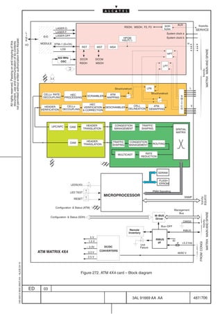
![4.31 ISA – ATM MATRIX 4X4 ENHANCED (ATM4X4D3)
The functional description of the board is similar to ISA ATM4X4V2 (refer to paragraph 4.32); the only
differences between the two boards is the number of TPs managed.
not permitted without written authorization from Alcatel.
All rights reserved. Passing on and copying of this
document, use and communication of its contents
As a matter of fact ATM4X4D3 board can manage up to 16 TPs among E1, E3, VC12, VC3, VC4, T3,
E1 IMA group.
4.32 ISA – ATM MATRIX 4X4 ENHANCED (ATM4X4V2)
(See Figure 273. on page and 493 )
This unit realize an ATM switching matrix with a total bandwidth of 622Mbit/s.
The board is able to manage up to 252 LT where LT is a physical or logical channel where is mapped an
ATM flow (E1, E3, VC12, VC3, VC4, T3, E1 IMA group)
On the board a local STM–1 access carrying an unstructured VC4 is managed.
The card perform the following functions:
[1] SDH signal processing
[2] ATM signal processing
[3] MATRIX
[4] MICROPROCESSOR
[5] Common part
[1] SDH signal processing
The SDH functions required are:
HPT, LPT and LPA.
– SOH bytes
Cross connection functions (MSP, HPC and LPC) are performed by the matrices present on the two
MATRIXN board (working in 1+1 configuration).
The MSA block is connected to the MATRIXN boards (main and spare) through 1+1 bidirectional links
at 622 Mbit/s , STM–4 equivalent capacity.
HPT, LPT and LPA blocks
Two data stream at frequency of 622 MHz are connected to the block called SWITCH in Figure 272.
on page 487, one coming from HPC matrix ( H link) and one from LPC matrix (L link).
Rx side: from matrix on MATRIXN to LPA or HPT
The task of the SWITCH block is to select one of the two busses coming from the matrices according to
the type of signal to be connected ( L if is structured or H if unstructured).
If the signal is structured the incoming signal (L Link) is sent through the SWITCH to the LPT and LPA
1AA 00014 0004 (9007) A4 – ALICE 04.10
block.
ED 03
3AL 91669 AA AA 488 / 706
706](https://image.slidesharecdn.com/1660smtecr5-2ed03-100224044520-phpapp01/85/1660-S-M-Tec-R5-490-320.jpg)
![• LPT (S12_TT_Sk): The LPT function terminates and processes the POH to determine the
status of the defined path attributes.
• J2: trail trace identifier is recovered –– TIM detection.
• V5[1,2]: BIP–2 is recovered –– Ex–BER, Signal Degrade alarm
not permitted without written authorization from Alcatel.
• V5[3]: REI bit is recovered and the derived performance primitives is reported.
All rights reserved. Passing on and copying of this
document, use and communication of its contents
• V5[8]: RDI information is recovered and reported.
• AIS or SSF detection –– SSF alarm
• LPA (S12/P12x_A_Sk): It extracts the VC12–POH and processes the TU12 pointer.
• V5[5–7]: Signal label detection in the byte V5[5–7] –– Signal label Mismatch
detection
• AIS or SSF is applied if Signal label Mismatch is detected
If the signal is unstructured the incoming signal (H Link) is sent through the SWITCH to the HPT block.
HPT (Sn_TT_Sk) : path trace information is recovered, REI information is recovered, HP–RDI
and UNEQ are detected, VC4 BIP–8 errored count block. TSF is applied if SSF or UNEQ or TIM
or AIS is detected.
TSD is applied if a condition of signal degrade is detected.
N1 byte extraction (Rx side): for the network Tandem Connection Termination Monitoring
function (TCT/TCM).
Tx side: from LPA or HPT to matrix on MATRIXN
The task of the SWITCH block is to sent the signal coming from HPT or LPT block towards the matrices
on the MATRIXN. The selection is made according to the type of signal to be connected ( L if is structured
or H if unstructured).
If the signal is structured the datas coming from ATM MAPPING block are sent through the LPT and LPA
blocks towards the SWITCH block.
• LPA (S12/P12x_A_So) : This block adapts user data for transport in the synchronous
domain. For asynchronous user data, lower order path adaptation involves bit justification. The
2.048 Mbit/s is inserted into a C–12 container (by means of asynchronous mapping), which is
synchronized (stuffing) with the correspondent TU–12.
• V5[5–7]: Signal label insertion in the byte V5[5–7].
• LPT (S12_TT_So) : The LPT function creates a VC–12 by generating and adding POH to a
C–12. The POH formats are defined in Recommendations G.708 and G.709.
• J2: trail trace identifier is generated.
• V5[1,2]: BIP–2 is calculated and transmitted.
• V5[3]: the number of errors is encoded in REI.
• V5[8]: RDI indication is inserted.
If the signal is unstructured the datas coming from ATM MAPPING block are sent through the HPT block
to the SWITCH block.
HPT (Sn_TT_So) : path trace identification insertion, RDI and REI indications insertion, VC–4
BIP–8 calculation and insertion, signal label insertion.
N1 byte insertion (Tx side): for the network Tandem Connection Termination Monitoring
function (TCT/TCM).
1AA 00014 0004 (9007) A4 – ALICE 04.10
HPOM, HSUT BLOCK (HSUT is not operative in this release)
ED 03
3AL 91669 AA AA 489 / 706
706](https://image.slidesharecdn.com/1660smtecr5-2ed03-100224044520-phpapp01/85/1660-S-M-Tec-R5-491-320.jpg)
![HPOM performs the monitoring of an equipped path while HSUT performs the termination of an
unequipped path.
From HPOM and HSUT are recovered :
not permitted without written authorization from Alcatel.
• the primitives used for Performance Monitoring (Errored block count, Defect seconds)
All rights reserved. Passing on and copying of this
document, use and communication of its contents
• switching criteria for SNCP/N protection
The two functions are alternative.
HPOM (Higher order path overhead monitoring)
Snm_TT_Sk : signal termination , J1 path recovering , REI information recovering, HP–RDI
detection (path status monitoring) , UNEQ and VC–AIS detection (signal label monitoring), VC4
BIP–8 Errored Block count. TSF is generated in case of SSF , UNEQ, TIM , AIS . TSD is generated
in case of SD.
HSUT (Higher order Supervisory Unequipped termination)
Sns_TT_Sk : path trace information recovery, REI recovery, HP–RDI detection (path status
monitoring), UNEQ and VC–AIS detection (signal label monitoring), VC4 BIP–8 Errored Block count.
Sns_TT_So : generation of an unequipped container , ”unequipped” insertion, trail trace identifier
generation, RDI and /or REI information generation, VC–4 BIP–8 calculation and insertion.
[2] ATM signal processing
RX side from SDH to MATRIX:
– ATM DEMAPPING: this block extract the ATM cells from the transmission path payload E1, E3, VC3,
VC4, VC4c; ATM DEMAPPING BLOCK receive the E1 and E3 frames contained in VC3 and VC4
payload for the processing performed in the equipment boards.
– CELL DELINEATION : cell delineation is the process which allow the identification of the cell
boundaries. It is performed on the cell stream extracted from the PDH/SDH frames
– DESCRAMBLER:for SDH and PDH the information field of each cell is descrambled with a self
synchronizing scrambler polynomial; descrambler is enable for a number of bit s equal to the length
of the information field, and again disabled for the following assumed header.
– HEC VERIFICATION AND CORRECTION: in this block HEC field in the cell header is checked; HEC
is used to achieved cell delineation.
The algorithm used can recover a single–bit error or detect headers with single and multi–bit errors.
– CELLs DECOUPLING: idle cells are extracted from the cell stream. Idle cells has been inserted in
the far end adaptation source function to reach the synchronous container capacity.
– IMA (Inverse Multiplexing over ATM) RX: NxE1 stream are bundled in a single high speed cell stream;
E1 stream are collected in a cyclical fashion among physical links preserving sequence( for details
on IMA refer to AF–PHY–0086.001).
– HEADER VERIFICATION: this function verifies that the first four octets of the ATM cell header are
recognizable as being a valid header pattern. Cells with unrecognized header patterns are discarded.
An indication of invalid header cell discard event is provided to the microprocessor interface where
1AA 00014 0004 (9007) A4 – ALICE 04.10
are counted.
ED 03
3AL 91669 AA AA 490 / 706
706](https://image.slidesharecdn.com/1660smtecr5-2ed03-100224044520-phpapp01/85/1660-S-M-Tec-R5-492-320.jpg)

![– ATM MAPPING: the cell stream is inserted into transmission path payload E1, E3, VC3, VC4, VC4c;
the E1 and E3 frames are sent to the output of the board mapped in VC12 and VC3 payload because
of the processing that will be done in the equipment boards.
not permitted without written authorization from Alcatel.
[3] MATRIX
All rights reserved. Passing on and copying of this
document, use and communication of its contents
The matrix is in charged of cross connect the incoming and outgoing cells according to the information
received by the microprocessor. In case of Soft Permanent Virtual Connection ( Soft–PVC) the P–NNI
signalling is supported.
[4] MICROPROCESSOR
The microprocessor present on the board performs the following functionality:
– configuration, alarm and status gathering of the ATM devices present on the board
– handling of the signalling packet receive from the matrix in case of Soft–PVC
– communication with the EC on the EQUICO (SNMP Link); using this channel performance and
management date are encapsulated and sent to the EC and from there to the Craft Terminal or O.S.
All the LEDS (except that for Unit–Failure) are driven by the microprocessor.
The maeaning of the LEDs and Push–Button is reported in Figure 272. on page 487.
[5] Common part
• RIBUS I/F
This block is used to read/write from/to the ”RIBUS” stream, to control the LED on the unit, to
release the Management–bus in case of power failure, and to use the remote inventory. RIBUS
I/F is powered by the + 3.3 Vdc supply by CONGI boards.
• REMOTE INVENTORY
It is the memory containing the board information, for identification purposes (see para. 3.17
on page 370 for details).
• M–BUS Driver
It drives the input–output gates of the Management–bus. These drivers can be disabled (by
the Bus–OFF signal) in case of power failure.
DC/DC CONVERTERS
Starting from the 48/60 V power supply the following voltages are generated:
– +1.5 Vdc, +3.3 Vdc, , +2.5 Vdc used to supply all the components in the board.
1AA 00014 0004 (9007) A4 – ALICE 04.10
ED 03
3AL 91669 AA AA 492 / 706
706](https://image.slidesharecdn.com/1660smtecr5-2ed03-100224044520-phpapp01/85/1660-S-M-Tec-R5-494-320.jpg)
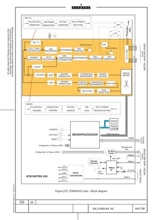
![4.33 ISA – ATM MATRIX 8X8 (ATM8X8)
(See Figure 274. on page 499 and Figure 275. on page 500)
not permitted without written authorization from Alcatel.
This unit realize an ATM switching matrix with a total bandwidth of 1.2 Gbit/s. As a matter of fact the unit
All rights reserved. Passing on and copying of this
document, use and communication of its contents
is two slot wide and it is connected with the SDH Matrix (MATRIXE) through two link at 622 Mbit/s.
The block diagram of the board has been been divided in two part depicted in Figure 274. on page 499
and Figure 275. on page 500; the part A describe the common part (microprocessor, led, DC/DC
converter) and the signal processing (ATM and SDH) of the first 622Mbit/s link, the part B describe the
signal processing (ATM and SDH) of the second 622Mbit/s link.
The board is able to manage up to 32 LT where LT is a physical or logical channel where is mapped an
ATM flow (E1, E3, VC12, VC3, VC4 and VC4–4c).
The card perform the following function:
[1] SDH signal processing
[2] ATM signal processing
[3] MATRIX
[4] MICROPROCESSOR
[5] Common part
[1] SDH signal processing
The SDH functions are:
– HPT
– LPT and LPA.
Cross connection functions (MSP, HPC and LPC) are performed by the matrices present on the two
MATRIXE board (working in 1+1 configuration).
HPT, LPT and LPA blocks
Two data stream at frequency of 622 MHz are connected to the block called SWITCH in Figure 274. on
page 499 , one coming from HPC matrix ( L link) and one from LPC matrix (X link); the same description
can be applied to Figure 275. on page 500 that depict the part B of the board.
Rx side: from matrix on MATRIXE to LPA or HPT
The task of the SWITCH block is to select one of the two busses coming from the matrices according to
the type of signal to be connected ( L if is structured or X if unstructured).
If the signal is structured the incoming signal (L Link) is sent through the SWITCH to the LPT and LPA
block.
• LPT (S12_TT_Sk): The LPT function terminates and processes the POH to determine the
status of the defined path attributes.
• J2: trail trace identifier is recovered –– TIM detection.
1AA 00014 0004 (9007) A4 – ALICE 04.10
• V5[1,2]: BIP–2 is recovered –– Ex–BER, Signal Degrade alarm
• V5[3]: REI bit is recovered and the derived performance primitives is reported.
• V5[8]: RDI information is recovered and reported.
• AIS or SSF detection –– SSF alarm
ED 03
3AL 91669 AA AA 494 / 706
706](https://image.slidesharecdn.com/1660smtecr5-2ed03-100224044520-phpapp01/85/1660-S-M-Tec-R5-496-320.jpg)
![• LPA (S12/P12x_A_Sk): It extracts the VC12–POH and processes the TU12 pointer.
• V5[5–7]: Signal label detection in the byte V5[5–7] –– Signal label Mismatch
detection
• AIS or SSF is applied if Signal label Mismatch is detected
not permitted without written authorization from Alcatel.
All rights reserved. Passing on and copying of this
document, use and communication of its contents
If the signal is unstructured the incoming signal (L Link) is sent through the SWITCH to the HPT block.
HPT (Sn_TT_Sk) : path trace information is recovered, REI information is recovered, HP–RDI
and UNEQ are detected, VC4 BIP–8 errored count block. TSF is applied if SSF or UNEQ or TIM
or AIS is detected.
TSD is applied if a condition of signal degrade is detected.
N1 byte extraction (Rx side): for the network Tandem Connection Termination Monitoring
function (TCT/TCM).
Tx side: from LPA or HPT to matrix on MATRIXE
The task of the SWITCH block is to sent the signal coming from HPT or LPT block towards the matrices
on the MATRIXE. The selection is made according to the type of signal to be connected ( L if is structured
or X if unstructured).
If the signal is structured the datas coming from ATM MAPPING block are sent through the LPT and LPA
blocks towards the SWITCH block.
• LPA (S12/P12x_A_So) : This block adapts user data for transport in the synchronous
domain. For asynchronous user data, lower order path adaptation involves bit justification. The
2.048 Mbit/s is inserted into a C–12 container (by means of asynchronous mapping), which is
synchronized (stuffing) with the correspondent TU–12.
• V5[5–7]: Signal label insertion in the byte V5[5–7].
• LPT (S12_TT_So) : The LPT function creates a VC–12 by generating and adding POH to a
C–12. The POH formats are defined in Recommendations G.708 and G.709.
• J2: trail trace identifier is generated.
• V5[1,2]: BIP–2 is calculated and transmitted.
• V5[3]: the number of errors is encoded in REI.
• V5[8]: RDI indication is inserted.
If the signal is unstructured the datas coming from ATM MAPPING block are sent through the HPT block
to the SWITCH block.
HPT (Sn_TT_So) : path trace identification insertion, RDI and REI indications insertion, VC–4
BIP–8 calculation and insertion, signal label insertion.
N1 byte insertion (Tx side): for the network Tandem Connection Termination Monitoring
function (TCT/TCM).
1AA 00014 0004 (9007) A4 – ALICE 04.10
ED 03
3AL 91669 AA AA 495 / 706
706](https://image.slidesharecdn.com/1660smtecr5-2ed03-100224044520-phpapp01/85/1660-S-M-Tec-R5-497-320.jpg)
![[2] ATM signal processing
N.B. The description that follows can be applied to both Figure 274. on page 499 and Figure 275.
on page 500
not permitted without written authorization from Alcatel.
All rights reserved. Passing on and copying of this
document, use and communication of its contents
RX side from SDH to MATRIX:
– ATM DEMAPPING: this block extract the ATM cells from the transmission path payload E1, E3, VC3,
VC4, VC4c; ATM DEMAPPING BLOCK receive the E1 and E3 frames contained in VC3 and VC4
payload for the processing performed in the equipment boards.
– CELL DELINEATION : cell delineation is the process which allow the identification of the cell
boundaries. It is performed on the cell stream extracted from the PDH/SDH frames
– DESCRAMBLER:for SDH and PDH the information field of each cell is descrambled with a self
synchronizing scrambler polynomial; descrambler is enable for a number of bit s equal to the length
of the information field, and again disabled for the following assumed header.
– HEC VERIFICATION AND CORRECTION: in this block HEC field in the cell header is checked; HEC
is used to achieved cell delineation.
The algorithm used can recover a single–bit error or detect headers with single and multi–bit errors.
– CELLs DECOUPLING: idle cells are extracted from the cell stream. Idle cells has been inserted in
the far end adaptation source function to reach the synchronous container capacity.
– HEADER VERIFICATION: this function verifies that the first four octets of the ATM cell header are
recognizable as being a valid header pattern. Cells with unrecognized header patterns are discarded.
An indication of invalid header cell discard event is provided to the microprocessor interface where
are counted.
– UPC/NPC:this function (policing) checks that the incoming traffic from a VPC is not violating the
agreed traffic contract.
UPC (User Parameter Control) and NPC (Network Parameter Control) perform the same function
but in different parts of the network (respectively at User Network Interface and Network Node
Interface )
– OAM: operations and maintenance function is done by using dedicated cells. Typically function are
cells monitoring, cells reporting, faults localization etc.
– HEADER TRANSLATION: this block performs on each virtual connection an header translation
which consist in a conversion of the external identification number (LTI/VPI/VCI) into an an internal
identification number for the user to network direction
– CONGESTION MANAGEMENT is the block that in the event of congestion is responsible to assure
that cell with loss priority will be discarded before than cell with high priority.
– TRAFFIC SHAPING:this function enhances the utilization of the buffer and matrix providing better
switch performance, especially for burst data.
1AA 00014 0004 (9007) A4 – ALICE 04.10
ED 03
3AL 91669 AA AA 496 / 706
706](https://image.slidesharecdn.com/1660smtecr5-2ed03-100224044520-phpapp01/85/1660-S-M-Tec-R5-498-320.jpg)

![[3] MATRIX
The matrix is in charged of cross connect the incoming and outgoing cells according to the information
received by the microprocessor. In case of Soft Permanent Virtual Connection ( Soft–PVC) the P–NNI
not permitted without written authorization from Alcatel.
signalling is supported.
All rights reserved. Passing on and copying of this
document, use and communication of its contents
[4] MICROPROCESSOR
The microprocessor present on the board performs the following functionality:
– configuration, alarm and status gathering of the ATM devices present on the board
– handling of the signalling packet receive from the matrix in case of Soft–PVC
– communication with the EC on the PQ2/EQC (SNMP Link); using this channel performance and
management date are encapsulated and sent to the EC and from there to the Craft Terminal or O.S.
All the LEDS (except that for Unit–Failure) are driven by the microprocessor.
The maeaning of the LEDs and Push–Button is reported in Figure 272. on page 487.
[5] Common part
• RIBUS I/F
This block is used to read/write from/to the ”RIBUS” stream, to control the LED on the unit, to
release the Management–bus in case of power failure, and to use the remote inventory. RIBUS
I/F is powered by the + 3.3 Vdc supply by CONGI boards.
• REMOTE INVENTORY
It is the memory containing the board information, for identification purposes (see para. 3.17
on page 370 for details).
• M–BUS Driver
It drives the input–output gates of the Management–bus. These drivers can be disabled (by
the Bus–OFF signal) in case of power failure.
DC/DC CONVERTERS
Starting from the 48/60 V power supply the following voltages are generated:
– + 5 Vdc used by the optical module
– +1.5 Vdc, –3.3 Vdc, –3.3 Vdc, –3.3 Vdc, +2.5 Vdc used to supply all the components
in the board.
1AA 00014 0004 (9007) A4 – ALICE 04.10
ED 03
3AL 91669 AA AA 498 / 706
706](https://image.slidesharecdn.com/1660smtecr5-2ed03-100224044520-phpapp01/85/1660-S-M-Tec-R5-500-320.jpg)
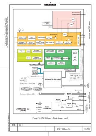
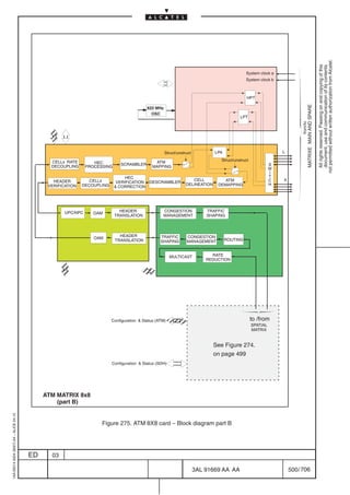
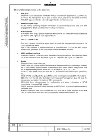
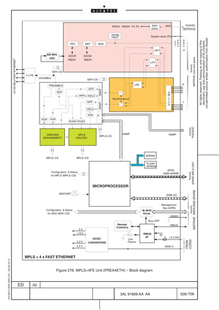
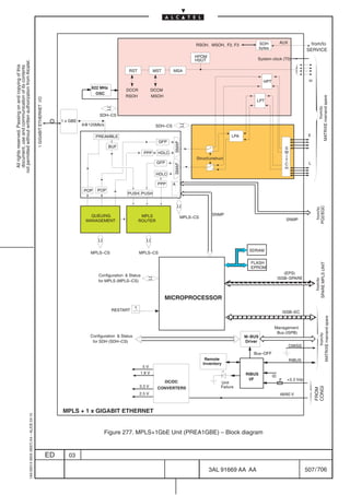
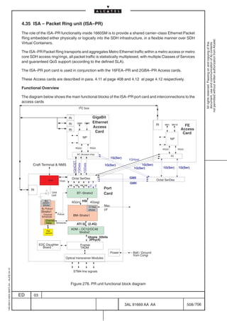

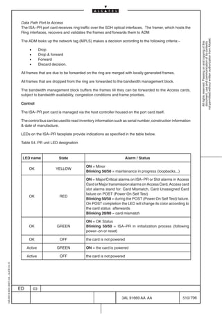

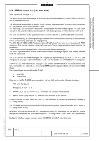
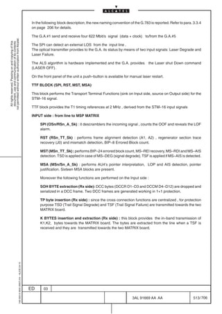
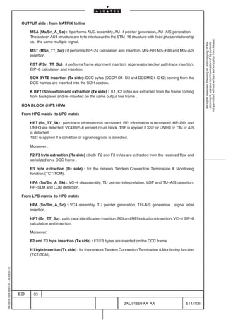
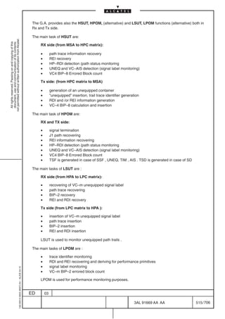

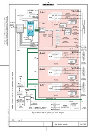
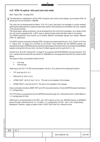
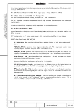


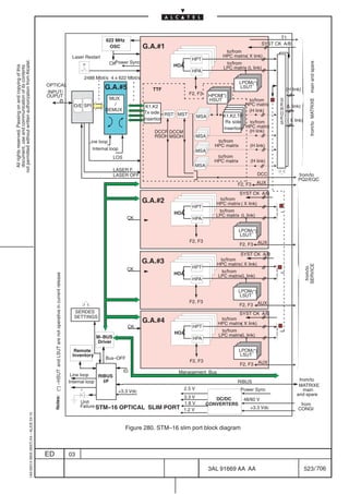
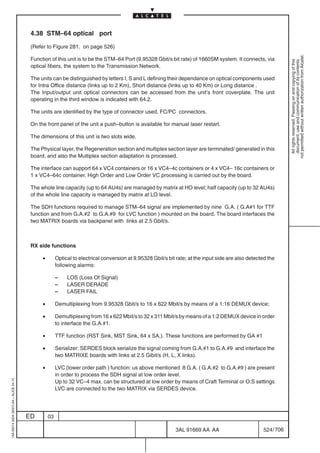
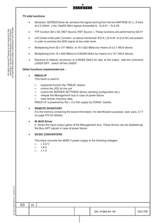
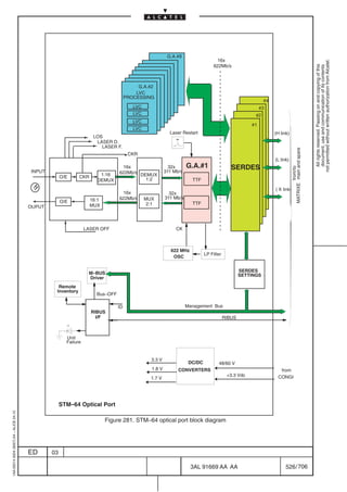
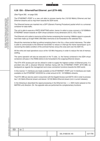
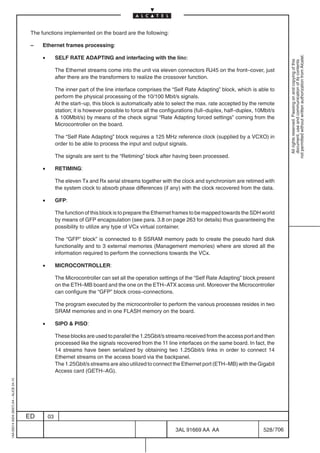
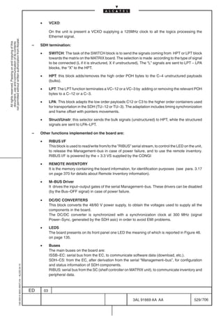
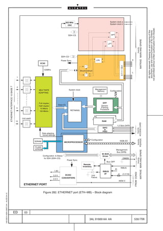
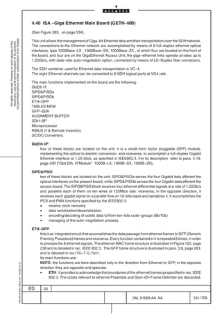
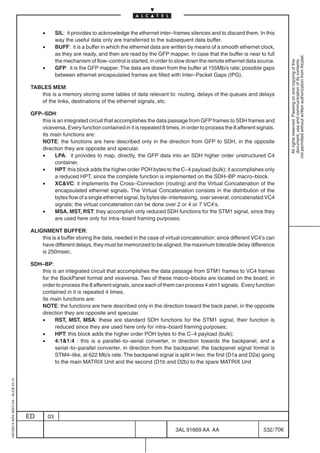
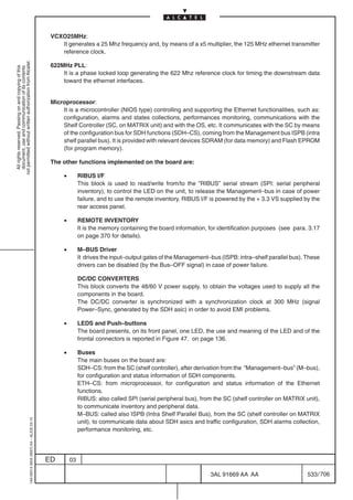
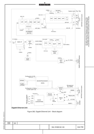
![4.41 ISA– Ethernet switch (ES1–8FE)
The board ISA–ES1–8FE mainly works as a LAN switching, and in particular it provides the service of
connecting two LANs as a point to point connection between two routers or switches through an SDH
not permitted without written authorization from Alcatel.
network.
All rights reserved. Passing on and copying of this
document, use and communication of its contents
The connections to the Ethernet network are accomplished by means of eight local 10/100 Base T
ethernet interfaces located on the front of the board, and eight ethernet over SDH interfaces through
back–panel.
The SDH container used for Ethernet data transportation are VC–4, VC–3, VC–12, VC3XV and VC12XV.
The main functions implemented on the board are the following:
[1] Ethernet Physical interface
[2] Ethernet Switch module
[3] Ethernet Mapper (GFP/LAPS)
[4] Bus converter
[5] SDH interfacing to Back Panel (TTF and LVC)
[6] Microprocessor
[7] RIBUS interface
[8] Power supply
[1] Ethernet Physical interface
This block supports the eight 10/100 Mbit/s ports. The 10/100 Mbit/s Ethernet MAC block is IEEE 802.3,
802.3x and 802.3ac compliant and supports Full Duplex/Half Duplex for 10/100 Mbit/s Ethernet MAC
(MAC implements the IEEE 802.3 MAC Control layer and PAUSE operation for flow control) mode of
operation.
In addition, 3 LED interface are provided for each port to reflect current status.
[2] Ethernet Switch module
In ISA ES1–8FE board, 16FE ports are used, in which 8 of them for 100BASE–T line side interface, while
other 8 for SDH mapper.
The basic functions supported are following listed:
• MAC based forwarding and autolearning
• VLAN based forwarding
• 802.1Q VLAN add/remove/swap
• Stacked VLAN (802.1Q format) add/remove/swap
• Multicast/Broadcast
• 802.3x flow control
• 802.1Q Priority bits management for queuing, WFQ scheduling
•
1AA 00014 0004 (9007) A4 – ALICE 04.10
Policing and bandwidth allocation
ED 03
3AL 91669 AA AA 535 / 706
706](https://image.slidesharecdn.com/1660smtecr5-2ed03-100224044520-phpapp01/85/1660-S-M-Tec-R5-537-320.jpg)
![[3] Ethernet Mapping over SDH (GFP/LAPS)
Ethernet packets are encapsulated and mapped into SDH frames for transmission. Ethernet mapper
supports 8 independent channels for EOS encapsulation.
not permitted without written authorization from Alcatel.
All rights reserved. Passing on and copying of this
document, use and communication of its contents
Each channel can be mapped with multi SDH containers with appropriate bandwidth, such as
VC12s/VT1.5, VC3s/STS–1s, or VC4s/STS–3c.
Both high order and low order concatenation are supported, moreover, virtual concatenation with LCAS
(Link Capacity Adjustment Scheme) providesr customer with powerful dynamic bandwidth adjustment
scheme to fit various needs.
Basic feature list as follows:
• Multi encapsulation mode supported:
– GFP Generic Framing Procedure (ITU–T G.7041)
– LAPS Link Access Procedure SDH (ITU–T X.86/X.85)
– BCP PPP Bridge Control Protocol (RFC 1662/2878)
• Low order/High order Contiguous and Virtual Concatenation supported
• Container supported:
– VC12–xv (x = 1 to 63)
– VC3–xv (x = 1 to 3)
• Differential delay compensation = 48 ms
[4] Bus converter
The task of the Bus converter is to translate 19 Mb/s A/D bus to 155 Mb/s data stream.
[5] SDH interfacing with Back Panel (TTF and LVC)
The TTF block is connected to the two central boards (MATRIXN) through 1 +1 links @622 Mbit/s in LVDS.
TTF (Transport Terminal Function) block provides SDH termination for Regenerator Section and Multiplex
Section.
The LVC block is connected both to the HPC matrices and to the LPC matrices on the MATRIXN card
through couple of 1+1 links @ 622 MBit/s working in protection, LVDS format, STM–4 equivalent capacity.
LVC circuits perform the HOA function (Higher Order Assembler) and the Lower Order functions LTCM
or LTCT sink, LPOM or LSUT sink, LSUT source and LTC source up to 4 STM1 equivalent.
[6] Microprocessor
It is a microcontroller controlling and supporting the Ethernet functionalities, such as: configuration,
alarms and states collections, performances monitoring, communications with the Shelf Controller
(SC, on MATRIX unit) and with the OS, etc. It communicates with the SC by means of the
configuration bus for SDH functions (SDH–CS), coming from the Management bus ISPB (intra shelf
1AA 00014 0004 (9007) A4 – ALICE 04.10
parallel bus). It is provided with relevant devices SDRAM (for data memory) and Flash EPROM (for
program memory).
ED 03
3AL 91669 AA AA 536 / 706
706](https://image.slidesharecdn.com/1660smtecr5-2ed03-100224044520-phpapp01/85/1660-S-M-Tec-R5-538-320.jpg)
![[7] RIBUS interface
This block is used to read/write from/to the ”RIBUS” serial stream (SPI: serial peripheral inventory), to
control the LED on the unit, to release the Management–bus in case of power failure, and to use the remote
not permitted without written authorization from Alcatel.
inventory. RIBUS I/F is powered by the + 3.3 VS supplied by the rear access panel.
All rights reserved. Passing on and copying of this
document, use and communication of its contents
The following information/alarms coming from the boards are collected and sent to EQUICO:
– Card type and slot identification
– Alim alarm : it arises in case of card power failure
– ISPB control: it disables the card access to the ISPB bus in case of board power failure or incase of
generic board failure.
– LED control: it commands the on/off status of the green/red INT LED present on each card.
Moreover the component permits to read/write the remote inventory.
[8] Power supply
This block converts the 48/60 V power supply, to obtain the voltages used to supply all the components
in the board.
Ethernet card internally uses five different power voltages.
The following voltages are needed: +3.3V , +2.5V, +1.8V, +1.5V, +3.3VS.
The other functions implemented on the board are:
• REMOTE INVENTORY
It is the memory containing the board information, for identification purposes (see para. 3.17
on page 370 for details).
• M–BUS Driver
It drives the input–output gates of the Management–bus (ISPB: intra–shelf parallel bus). These
drivers can be disabled (by the Bus–OFF signal) in case of power failure.
DC/DC CONVERTERS
• LEDS and Push–buttons
The board presents, on its front panel, nine LEDs, the use and meaning of the LED and of the
frontal connectors is reported in Figure 47. on page 136.
1AA 00014 0004 (9007) A4 – ALICE 04.10
ED 03
3AL 91669 AA AA 537 / 706
706](https://image.slidesharecdn.com/1660smtecr5-2ed03-100224044520-phpapp01/85/1660-S-M-Tec-R5-539-320.jpg)
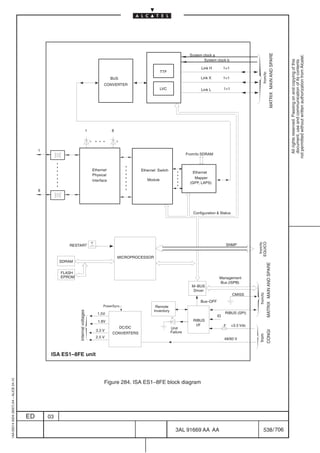
![4.42 ISA– Ethernet switch (ES1–8FX)
The description of the board is similar to the ISA ES1–8FE (refer to paragraph 4.41 on page 535) taking
into account that ISA ES1–8FX has eight 100 Base FX Optical SFP module instead of 10/100 Base T.
not permitted without written authorization from Alcatel.
All rights reserved. Passing on and copying of this
document, use and communication of its contents
4.43 ISA– Ethernet switch (ES4–8FE)
The board ISA–ES4–8FE mainly works as a LAN switching and as gateway from the Ethernet traffic
towards the SDH network.
In particular it provides the service of connecting two LANs and can be applied mainly in three scenario:
[1] Point to point application where a point to point connection is set–up between two routers or switches
through an SDH network.
[2] Ring application where local interfaces add/drop Ethernet traffic on a ring of virtual concatenated
paths in the SDH network.
[3] HUB application where several switches or routers convey traffic towards a single machine (for
example POP router)
The connections to the Ethernet network are accomplished by means of 8 local 10/100 Base T ethernet
interfaces located on the front of the board, and 16 ethernet over SDH interfaces through back–panel
which has a 622 Mbit/s equivalent throughput.
The front panel hosts also one Small Form factor Pluggable module supporting a Gigabit Ethernet
interface, the ninth local interface.
The SDH container used for Ethernet data transportation are VC–4, VC4XV (only when Gbit Ethernet
interface will be managed) VC–3, VC–12, VC3XV and VC12XV.
The main functions implemented on the board are the following:
[1] Ethernet Physical interface
[2] Ethernet Switch module
[3] Ethernet Mapper (GFP/LAPS)
[4] SDH interfacing to Back Panel (TTF and LVC)
[5] Local Microprocessor
[6] RIBUS interface
[7] Power supply
[1] Ethernet Physical interface
This block supports the eight 10/100 Mbit/s ports. The 10/100 Mbit/s Ethernet MAC block is IEEE 802.3,
802.3x and 802.3ac compliant and supports Full Duplex only for 10/100 Mbit/s Ethernet MAC (MAC
implements the IEEE 802.3 MAC Control layer and PAUSE operation for flow control) mode of operation;
autonegotiation is also supported.
1AA 00014 0004 (9007) A4 – ALICE 04.10
ED 03
3AL 91669 AA AA 539 / 706
706](https://image.slidesharecdn.com/1660smtecr5-2ed03-100224044520-phpapp01/85/1660-S-M-Tec-R5-541-320.jpg)
![[2] Ethernet Switch module
In ISA ES4–8FE board, 25 ports are used, in which 8 of them for 100BASE–T line side interface, one for
1000Base SX, LX, ZX while other 16 for SDH mapper.
not permitted without written authorization from Alcatel.
All rights reserved. Passing on and copying of this
document, use and communication of its contents
The basic functions supported are following listed:
• MAC based forwarding and autolearning
• VLAN based forwarding
• 802.1Q VLAN add/remove/swap
• Stacked VLAN (802.1Q format) add/remove/swap
• Multicast/Broadcast
• 802.3x flow control
• 802.1Q Priority bits management for queuing, WFQ scheduling
• Policing and bandwidth allocation
[3] Ethernet Mapping over SDH (GFP/LAPS)
Ethernet packets are encapsulated and mapped into SDH frames for transmission. Ethernet mapper
supports 16 independent channels for EOS (Ethernet Over SDH) encapsulation.
Each channel can be mapped with multi SDH containers with appropriate bandwidth, such as VC12,
VC12XV, VC3, VC3XV, VC4 or VC4XV (with local Gb Ethernet interface)
Both high order and low order concatenation are supported, moreover, virtual concatenation with LCAS
(Link Capacity Adjustment Scheme) provides customer with powerful dynamic bandwidth adjustment
scheme to fit various needs.
Basic feature list as follows:
• Multi encapsulation mode supported:
– GFP Generic Framing Procedure (ITU–T G.7041)
– LAPS Link Access Procedure SDH (ITU–T X.86/X.85)
– BCP PPP Bridge Control Protocol (RFC 1662/2878)
• Low order/High order Contiguous and Virtual Concatenation supported
• XV Container supported:
According to the port configuration two different operation mode are available for ISA
ES–4–8FE as explained in the table below:
XV type XV container supported
SMII operating mode GMII operating mode
VC12–xv (x = 1 to 50) (x = 1 to 63)
VC3–xv (x = 1 to 2) (x = 1 to 12)
VC4–xv (x = 1 ) (x = 1 to 4 )
1AA 00014 0004 (9007) A4 – ALICE 04.10
The choice between SMII or GMII operation is made via Craft Terminal.
• Differential delay compensation = 48 ms
ED 03
3AL 91669 AA AA 540 / 706
706](https://image.slidesharecdn.com/1660smtecr5-2ed03-100224044520-phpapp01/85/1660-S-M-Tec-R5-542-320.jpg)
![[5] SDH interfacing with Back Panel (TTF and LVC)
The TTF block is connected to the two central boards (MATRIXN) through 1 +1 links @622 Mbit/s in LVDS.
not permitted without written authorization from Alcatel.
TTF (Transport Terminal Function) block provides SDH termination for Regenerator Section and Multiplex
All rights reserved. Passing on and copying of this
document, use and communication of its contents
Section.
The LVC block is connected both to the HPC matrices and to the LPC matrices on the MATRIXN card
through couple of 1+1 links @ 622 MBit/s working in protection, LVDS format, STM–4 equivalent capacity.
LVC circuits perform the HOA function (Higher Order Assembler) and the Lower Order functions LTCM
or LTCT sink, LPOM or LSUT sink, LSUT source and LTC source up to 4 STM1 equivalent.
[6] Local Microprocessor
It controls and supports the Ethernet functionalities (Ethernet Physical Interface, Ethernet Switch Module
and Ethernet Mapper): configuration, alarms and states collections, performances monitoring,
communications with the OS (SNMP).
The microprocessor is provided with relevant devices SDRAM (for data memory), Flash EPROM (for
program memory) and Compact Flash.
External Shelf Controller (SC) controls SDH related circuits by ISPB bus.
[7] RIBUS interface
This block is used to read/write from/to the ”RIBUS” serial stream (SPI: serial peripheral inventory), to
control the LED on the unit, to release the Management–bus in case of power failure, and to use the remote
inventory. RIBUS I/F is powered by the + 3.3 VS supplied by the rear access panel.
The following information/alarms coming from the boards are collected and sent to EQUICO:
– Card type and slot identification
– Alim alarm : it arises in case of card power failure
– ISPB control: it disables the card access to the ISPB bus in case of board power failure or incase of
generic board failure.
– LED control: it commands the on/off status of the green/red INT LED present on each card.
Moreover the component permits to read/write the remote inventory.
[8] Power supply
This block converts the 48/60 V power supply, to obtain the voltages used to supply all the components
in the board.
Ethernet card internally uses five different power voltages.
The following voltages are needed: +3.3V , +2.5V, +1.8V, +1.5V, +3.3VS.
1AA 00014 0004 (9007) A4 – ALICE 04.10
ED 03
3AL 91669 AA AA 541 / 706
706](https://image.slidesharecdn.com/1660smtecr5-2ed03-100224044520-phpapp01/85/1660-S-M-Tec-R5-543-320.jpg)

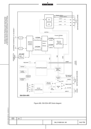
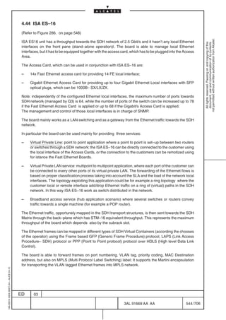
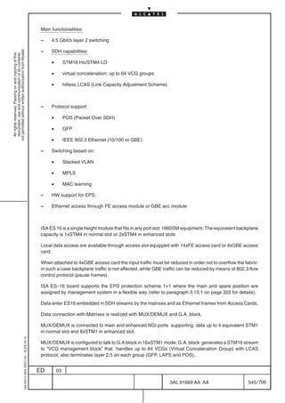
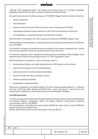

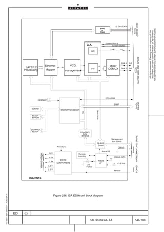
![4.45 4 X ANY HOST C card
(Refer to Figure 287. on page 553)
not permitted without written authorization from Alcatel.
This port realizes the mapping of up to 4 “client” signals, into an equivalent bandwidth up to 16 AU4’s; the
All rights reserved. Passing on and copying of this
document, use and communication of its contents
client allocation depends on the operative bitrate of client signal to be mapped, so as the availability of
16 AU4’s (rather than 8 AU4’s) is related to the type of slot used for the board equipment (refer to paragraph
3.10 on page 293 for details).
AU4’s carrying ’client’ signals mapped can be, then, cross–connected at HO level by MATRIX card.
’Client’ interfacing is performed through specific ’pluggable’ modules.
Serial data provided by client modules is then processed by the “primary and secondary 2xANY“ blocks
in order to realize a ’bit–per–bit’ mapping of client signals supported, that result, after each block
processing, ’virtually concatenated’ into an 8xSTM1 bandwidth.
A specific FPGA interfaces the two “primary and secondary 2xANY“ blocks performing ’client mapping’
and then provides the whole SDH chain of functions from HPT to RST; this device allows also the
optimization of client allocation into the available 8xSTM1’s, when equipped in ’H.S.’ slots (refer to
paragraph 3.10 on page 293 for details).
The data signal is, then, exchanged to MATRIX card, through the G.A. block operating as electrical
interface: equivalent STM16 is received (transmitted) from FPGA block and provided (received) to
MATRIX card with NGI framed format (X, L, H links in Figure 287. )
Note – TTF blocks supported by FPGA and G.A block are used only for interface purpose. An internal
oscillator (VCXO 622.08 Mb/s) is hosted in order to handle CRU EPS events (phisically on MATRIX unit)
with no impact on ’client’ traffic transmitted to line.
TX SIDE
– 4 X ANY module blocks: the client receiver interface regenerates the incoming client signal and
recovers the relative timing; the interface characteristics are related to client type (refer to paragraph
5.7 on page 619). Line loopback commands for each interface are received by “Alarms and Control”
block.
– Primary and Secondary 2xANY blocks: inside theese blocks the HPA function is performed; more
in details:
• client clock adaptation
• virtual concatenation
• C2 insertion
– HPT block:
HPT source is performed for all VC–4 in FPGA block; the following function are performed:
• B3: Bit interleaved parity (BIP–8) is computed over all bits of the previous VC–4 and placed in
B3 byte position.
• G1[1–4]: The number of errors indicated in RI_REI (remote error indication extracted in HPT
sk) is encoded in the REI (bits 1 to 4 of the G1 byte)
1AA 00014 0004 (9007) A4 – ALICE 04.10
• G1[5]: When there is an active RI_RDI (remote defect indication extracted in HPT sk), the RDI
indication will be sent in bit 5 of G1 byte. Upon termination of the above conditions, the RDI
indication will be removed.
ED 03
3AL 91669 AA AA 549 / 706
706](https://image.slidesharecdn.com/1660smtecr5-2ed03-100224044520-phpapp01/85/1660-S-M-Tec-R5-551-320.jpg)
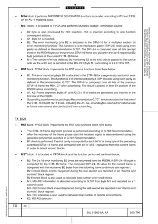
![– MSA block: pointer detection process.
The pointer interpreter can detect two defect conditions:
• Loss Of Pointer (LOP);
not permitted without written authorization from Alcatel.
• AU–AIS.
All rights reserved. Passing on and copying of this
document, use and communication of its contents
If either of these defect conditions are detected, then a logical all–ones (AIS) signal is generated
– HPT block:
• B3: The error monitoring byte B3 is recovered. BIP–8 is computed for the VC–4 frame. The
computed BIP–8 value for the current frame is compared with the recovered B3 byte from the
following frame.
The process for detecting excessive errors and signal degrade is described in ITU–T
Reccomandation. G.806.
B3 Errored Block event happened during the last second of VC–4 #0 are reported in “Alarms
and controls” block register.
B3 Errored Block of VC–4 #0 are also used to calculate total number of errored block.
• G1[1–4]: The REI is recovered and the derived performance primitives is reported for
processing.
• G1[5]: The RDI defect is processed as described in ITU–T Reccomandation. G.806.
• C2: Unequipped defect is detected (refer to G.783)
– HPA block:
The following function are performed:
• C2 extraction: Byte C2 is recovered from VC–4 #0. If a dPLM is detected (see ITU–T G.806),
then it will be reported in an “Alarms and controls” block register.
• H4 extraction: Multiframe indicator is derived from the H4 byte. The received H4 value is
compared to the next expected value in the multiframe sequence. The H4 value is assumed to
be in phase when it is coincident with the expected value. If several H4 values are received
consecutively not as expected but correctly in sequence with a different part of the multiframe
sequence, then subsequent H4 values will be expected to follow this new alignment. If several
H4 values are received consecutively not correctly in sequence with any part of the multiframe
sequence, then a loss of multiframe (LOM) event is reported. When several H4 values have
been received consecutively correctly in sequence with part of the multiframe sequence, then
the event will be ended and subsequent H4 values will be expected to follow the new alignment.
• extraction of payload from packetsand process the heaer content
• automatic client based band and latency preset
• client clock adaptation
1AA 00014 0004 (9007) A4 – ALICE 04.10
ED 03
3AL 91669 AA AA 551 / 706
706](https://image.slidesharecdn.com/1660smtecr5-2ed03-100224044520-phpapp01/85/1660-S-M-Tec-R5-553-320.jpg)
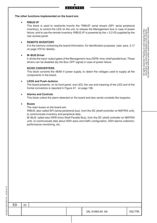
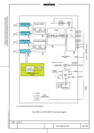

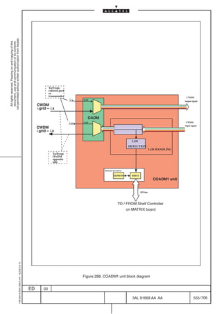

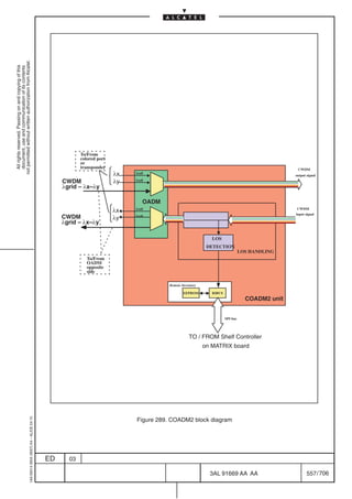

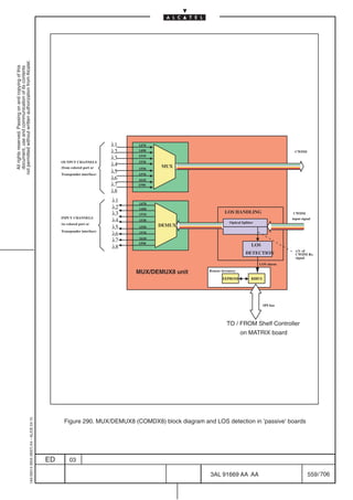
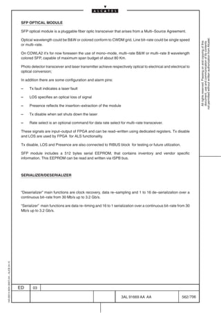
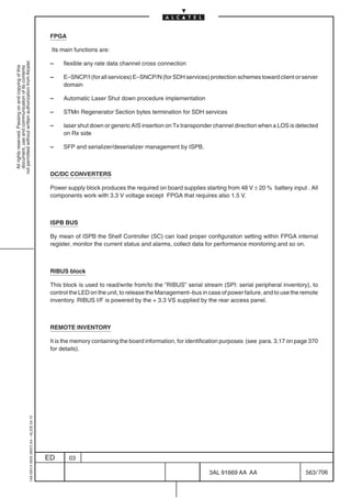
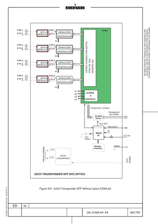

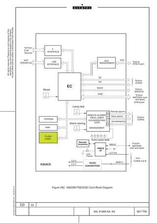
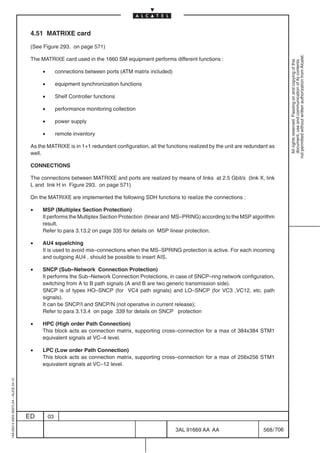
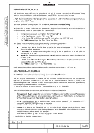
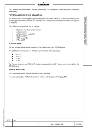
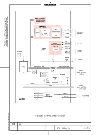
![4.52 CONGI card
(See Figure 294. on page 576)
not permitted without written authorization from Alcatel.
The 1660SM equipment can house two CONGI cards, referred as CONGI A main (slot 10) and CONGI
All rights reserved. Passing on and copying of this
document, use and communication of its contents
B (slot 12).
They are not intended as main and spare : each card provides a set of functions . Both units are necessary
to provide the complete set.
CONGI A can be used as stand alone but in this case only a subset of interfaces can be used .
Table 55. reports the interfaces present on each CONGI card.
Table 55. CONGI A and CONGI B interfaces
CONGI A (slot 10) CONGI B (slot 12)
POWER POWER
Housekeeping Remote Alarms (a subset) Housekeeping Remote Alarms ( a subset)
Rack lamps (R/M) Not used
QMD (Q2) Not used
Q3 10 base 2 Not used
Q3 10 base T Not used
INT led INT led
The main functions performed by the unit are:
[1] Input power stage
[2] AND/OR and Remote Alarms
[3] Housekeeping interface (only on CONGI in slot 10)
[4] R/M interface (only on CONGI in slot 10)
[5] QMD interface (only on CONGI in slot 10)
[6] RIMMEL interface
[7] Q3/QB3 interface (only on CONGI in slot 10)
[8] Remote inventory
1AA 00014 0004 (9007) A4 – ALICE 04.10
ED 03
3AL 91669 AA AA 572 / 706
706](https://image.slidesharecdn.com/1660smtecr5-2ed03-100224044520-phpapp01/85/1660-S-M-Tec-R5-574-320.jpg)
![[1] Input power stage
This circuit decouples the power station battery .
It contains the ”Main Power block” with two fuses, EMI input filters, a ”protection circuit block” , a ”step
not permitted without written authorization from Alcatel.
up converter” to provide –9 V and a DC/DC converter to provide the +3.3 V to the RIBUS I/F block ( see
All rights reserved. Passing on and copying of this
document, use and communication of its contents
para. 3.17 on page 370 for details ). In case of fuse broken an alarm is generated (FUSE)2.
A solder strap is present to provide the main power (48V) in modality “two wires” (if +Vbatt is connected
to ground or “three wire” (if + Vbatt is not connected to ground) in order to obtain a DC/I decoupling system.
[2] AND/OR and Remote Alarms
The circuit generates the remote alarms and lights up the the Rack lamps in case of station battery fault.
It is powered from the 3.3Vdc power from the service battery and uses it to control the station battery. In
case of loss of 3.3 Vdc a PWANDOR alarm is generated.
The AND/OR circuit monitors the station battery and provides an alarm (BAT FAIL) in case the voltage
level decreases more than 20 % of the nominal value. If BAT FAIL alarm of the CONGI in slot 10 or the
same alarm of the CONGI in slot 12 are present , the ORALIM alarm is generated and set to the PQ2/EQC
card.
Table 56. on page 573 and Table 57. on page 574 report a brief description of the alarms provided by
the AND/OR block respectively on CONGI in slot 10 and CONGI in slot 12 . They are all Electronic Ground
contacts (GND = alarm, OPEN = no alarm) sent towards the housekeeping and remote alarms connector.
Table 56. Remote alarm provided by the AND/OR block available on CONGI in slot 10
ACRONYM DESCRIPTION
T*TOR Fault or loss of one station battery .
It concurs to generate NURG, T*NURG and RNURG (it can be stored)
T*AND Fault or loss of both batteries stations. It concurs to generate T*URG and RURG (it
can be stored).
T*INT It indicates an internal alarm. It is received from PQ2/EQC
T*URG It indicates an urgent alarm. It is provided from PQ2/EQC
T*NURG It indicates a not urgent alarm. It is received from PQ2/EQC
N.B. On the Craft Terminal (C.T.) and on the Operation System (O.S). application the T*URG, and
T* NURG remote alarm are named in a different way; the relation between this two terminology
is explained in Table 77. on page 650.
1AA 00014 0004 (9007) A4 – ALICE 04.10
2. For the right management of the FUSE alarm refer to MAINTENANCE section of the METRO
OMSN C.T Operator’s Handbook. As a matter of fact some setting must be checked when two CONGI
with different Factory code / ANV suffix are equipped in the subrack.
ED 03
3AL 91669 AA AA 573 / 706
706](https://image.slidesharecdn.com/1660smtecr5-2ed03-100224044520-phpapp01/85/1660-S-M-Tec-R5-575-320.jpg)
![Table 57. Remote alarm provided by the AND/OR block available on CONGI in slot 12
ACRONYM DESCRIPTION
T*TORC It indicates a loss of +3.3V generated by the on board DC/DC converter of one
not permitted without written authorization from Alcatel.
CONGI card.
All rights reserved. Passing on and copying of this
document, use and communication of its contents
T*IND Indeterminate alarm synthesis. Indicate synthesis of alarms not associated to other
severity (not used)
T*TUP It indicates an PQ2/EQC microprocessor fault (it can be stored)
T*TANC It indicates loss of + 3.3 V generated by the on board DC/DC converters of both
CONGI cards (it can be stored).
LOSQ2 It indicates loss of communication with the Operation System (not used)
[3] Housekeeping interface
Two Housekeeping operating mode are supported for CONGI unit:
– CONGI unit preset 2 wire provide 6 inputs and 2 outputs contacts suitable for customer purpose.
– CONGI unit preset 3 wire provide 4 inputs and 2 outputs contacts suitable for customer purpose.
[4] R/M interface
It is used to connect the rack lamps and incoming call signal.
Table 58. Rack lamps signals
ACRONYM FUNCTION
T*RATTD alarms storing
T*RURG urgent alarm
T*RNURG not urgent alarm
T*CH incoming call
T*TOR absence of one battery
N.B. On the Craft Terminal (C.T.) and on the Operation System (O.S). application the T*RURG, and
T* RNURG remote alarm sent toward the rack lamp are named in a different way; the relation
between this two terminology is explained in Table 77. on page 650.
[5] QMD interface
It is a RS–485 interface that allows the dialogue between the NE (EC function) and a non SDH equipment.
In this case the NE acts as a mediation device.
[6] RIMMEL interface
This block provide a serial communication interface with the FANS Shelf in order to receive information
like presence of fans unit, fan alarms, fans unit remote inventory etc. (for details about connection with
FANS Shelf refer to Installation Handbook).
“Rimmel block” is also connected with the Shelf Controller (housed on the MATRIXE) and Equipment
Controller (housed on the PQ2/EQC) in order to:
– manage the HOUSEKEEPING contact
– provisioning remote alarm
1AA 00014 0004 (9007) A4 – ALICE 04.10
– read the 2/3 wire operating mode
ED 03
3AL 91669 AA AA 574 / 706
706](https://image.slidesharecdn.com/1660smtecr5-2ed03-100224044520-phpapp01/85/1660-S-M-Tec-R5-576-320.jpg)
![[7] Q3/QB3 interface
The Q3/QB3 interface on CONGI is used for OS connection. Two connectors are available :
– 2 BNC for 10 Base 2 connection type
not permitted without written authorization from Alcatel.
All rights reserved. Passing on and copying of this
document, use and communication of its contents
– RJ45 for 10 base T connection type.
The Coaxial Transceiver Interface (CTI) circuit performs the driver/receiver interface between the Q3/QB3
coaxial cable ( BNC) and the universal ethernet adapter (AUI).
The purpose of the AUI adapter is to adapt the signal, coming from the Equipment Controller on the
PQ2/EQC, to the LAN interface. It is directly connected to the RJ45 connector or through CTI to BNC
connector.
[8] Remote inventory
It is the memory used to maintain the board history and communication and routing data relevant to the
NE ;Remote Inventory activity is managed by the RIBUS I/F block as described on para. 3.17 on page
370.
1AA 00014 0004 (9007) A4 – ALICE 04.10
ED 03
3AL 91669 AA AA 575 / 706
706](https://image.slidesharecdn.com/1660smtecr5-2ed03-100224044520-phpapp01/85/1660-S-M-Tec-R5-577-320.jpg)
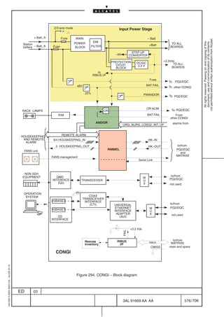
![4.53 SERVICE card
(See Figure 295. on page 582)
not permitted without written authorization from Alcatel.
The SERVICE card provides the following functions :
All rights reserved. Passing on and copying of this
document, use and communication of its contents
[1] AUX (auxiliary) channels management
[2] Input/output clock management
[3] EOW channels management
[4] POWER SUPPLY for internal board use.
[1] AUX channels management
It provides :
– four G.703 64 Kbit/s channels, ITU–T G.703 compliant
– four V11 channels , every one composed by data input, data output and clock
– four RS–232 channels
– two 2 Mbit/s G.703 signals that can be used as auxiliary channels
All the electrical interfaces are managed by the Matrix present on the unit.
[2] Input/Output clock management
Function performed:
– the unit can receives up to two 2 MHz clock (T3a and T3b) or up to two 2Mbit/s signals (T6a and T6b)
that could be used to synchronize the N.E. The unit provide software programmability to switch
between the two mode.
– the unit provides up to two 2 MHz clock (T4a and T4b) or up to two 2Mbit/s signals (T5a and T5b)
that can be used by another N.E. for synchronism purpose. The unit provide software
programmability to switch between the two mode.
[3] EOW management
The EOW channels allows to realize two different connections types:
a) between two stations (selective call)
b) omnibus call (one station is connected with all the other
To this purpose a telephone jack is present on the unit front panel.
Two extension channels with different connectors (RJ45 and RJ11) are available to establish a connection
with an external telephone set.
Moreover the channel on RJ11 can be used to establish a connection with an external telephone network
(future application).
The ”Omnibus call” is identified with ”00”.
1AA 00014 0004 (9007) A4 – ALICE 04.10
ED 03
3AL 91669 AA AA 577 / 706
706](https://image.slidesharecdn.com/1660smtecr5-2ed03-100224044520-phpapp01/85/1660-S-M-Tec-R5-579-320.jpg)
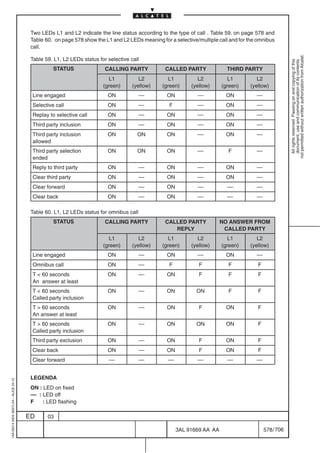


![Digital party line
The function performed by the Digital Party Line are:
not permitted without written authorization from Alcatel.
– manages the information coming from the SOH matrix
All rights reserved. Passing on and copying of this
document, use and communication of its contents
– detects DTMF code coming from the different channels
– party line
– manages LEDs , buzzer , push buttons and speech extensions present on the card front unit
– receives configuration information from the ”Management Bus”
AD/DA
This block is a voice–band audio processor and perform the transmit encoding (A/D conversion) and
receive decoding (D/A conversion) together with transmit and receive filtering for voice–band
communication systems.
Other functions implemented are :
• RIBUS I/F
This block is used to read/write from/to the ”RIBUS” stream, to control the LED on the unit, to
release the Management–bus in case of power failure, and to use the remote inventory:
• REMOTE INVENTORY
It is the memory containing the board information, for identification purposes (see para. 3.17
on page 370 for details).
• M–BUS Driver
It drives the input–output gates of the Management–bus. These drivers can be disabled (by
the Bus–OFF signal) in case of power failure.
[4] POWER SUPPLY
The unit receives via backpanel connectors the –48V coming from CONGI boards.
The DC/DC converter present on the board generates the following voltage:
• + 3.3 V
• + 2.5 V to supply the party line and the SOH Matrix
• – 9 V to supply the phone
The Remote–Inventory and RIBUS–I/F blocks are powered by the 3.3 V power service coming from the
CONGI boards .
1AA 00014 0004 (9007) A4 – ALICE 04.10
ED 03
3AL 91669 AA AA 581 / 706
706](https://image.slidesharecdn.com/1660smtecr5-2ed03-100224044520-phpapp01/85/1660-S-M-Tec-R5-583-320.jpg)
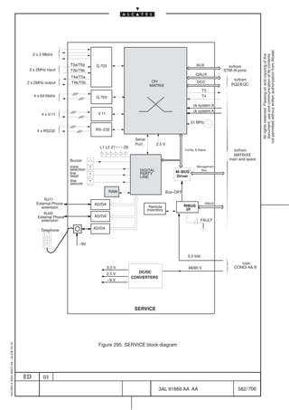
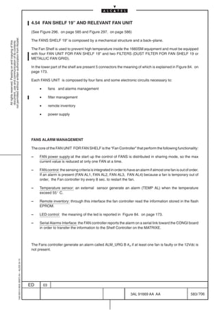

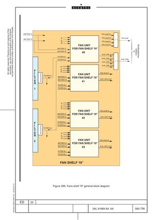
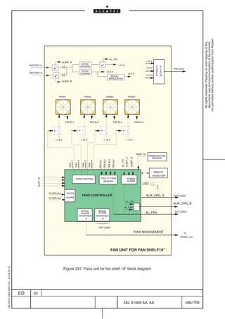

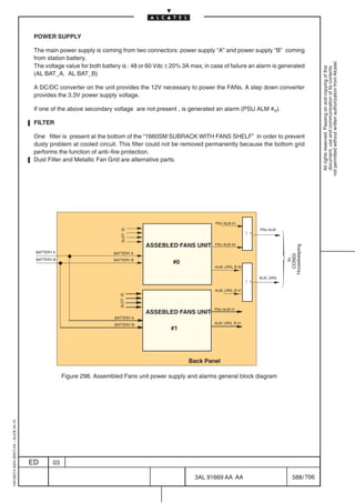
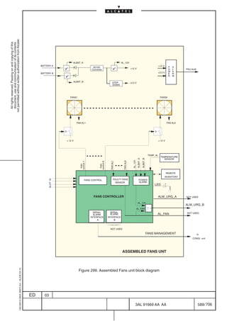

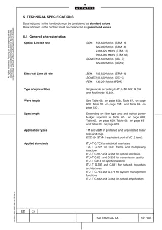
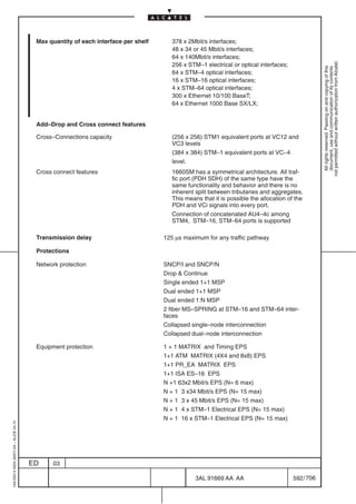
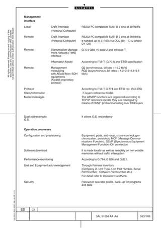
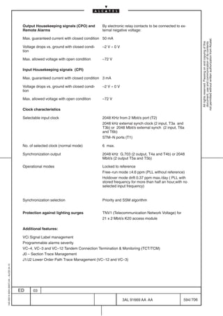

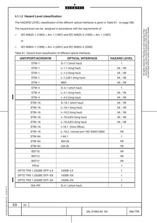
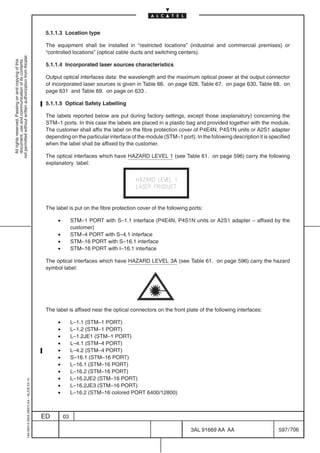
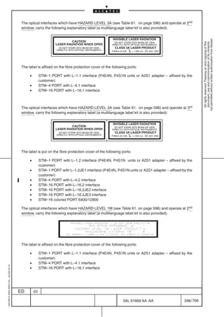


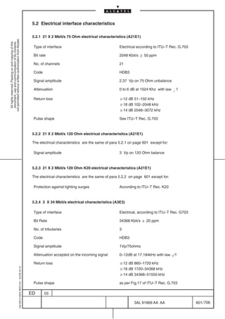
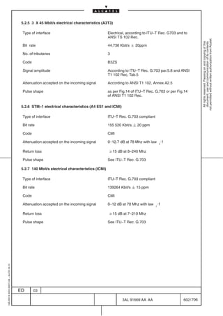
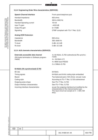
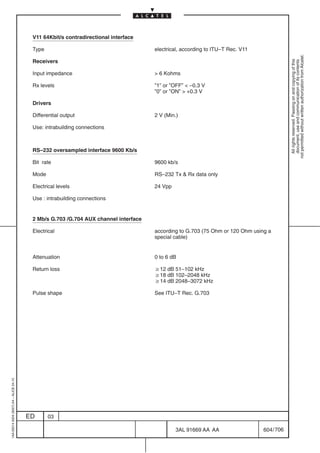
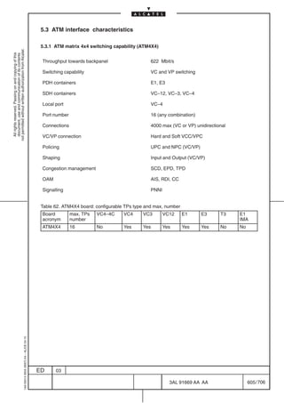
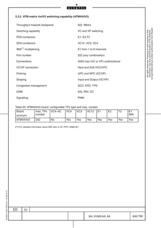
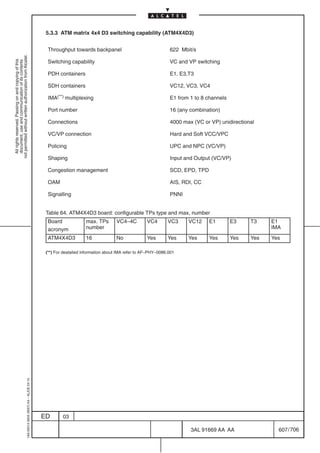

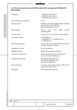
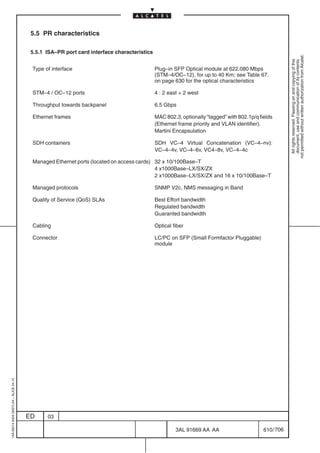
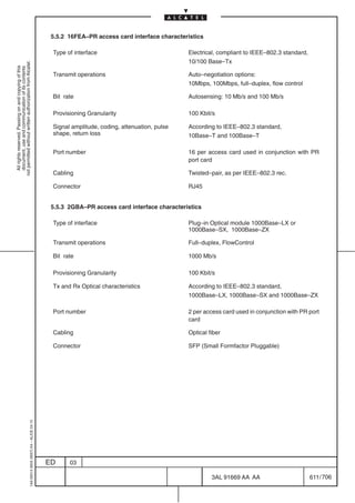
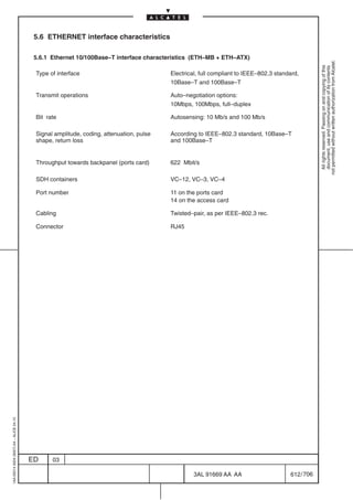
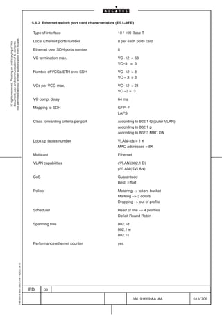
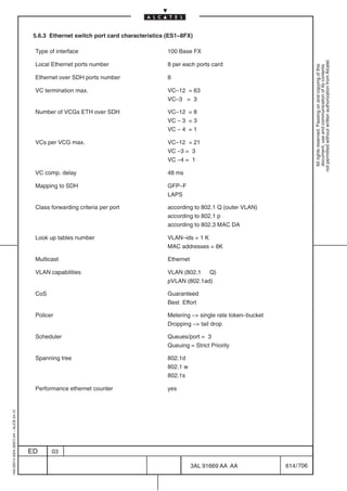
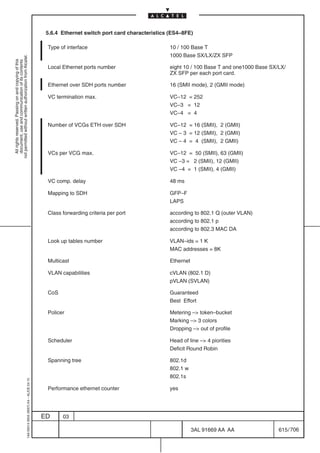
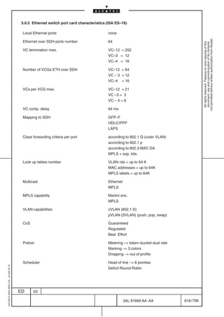
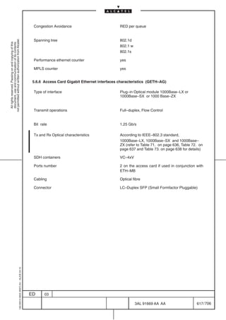
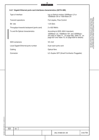
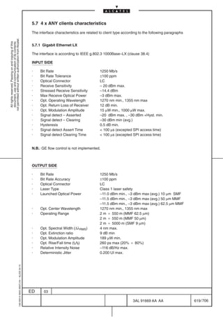
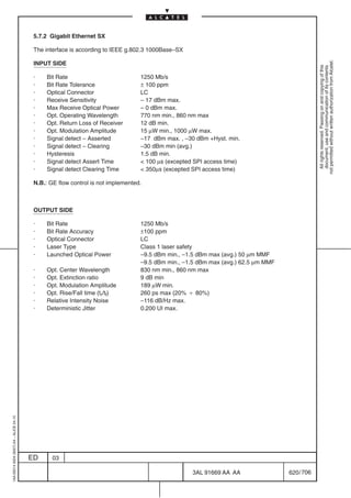
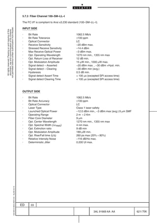
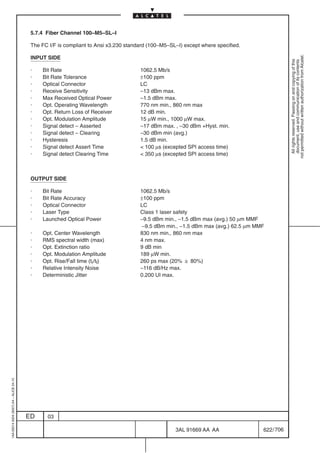
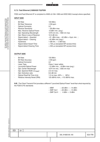
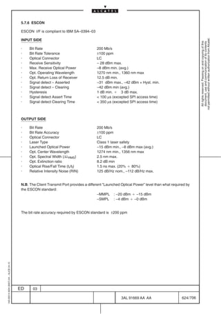
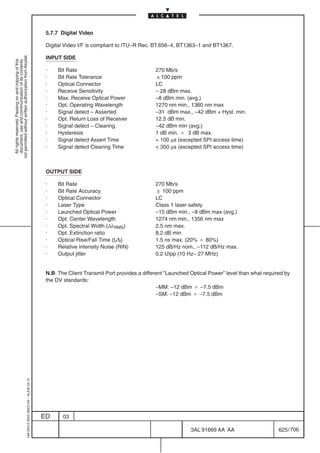
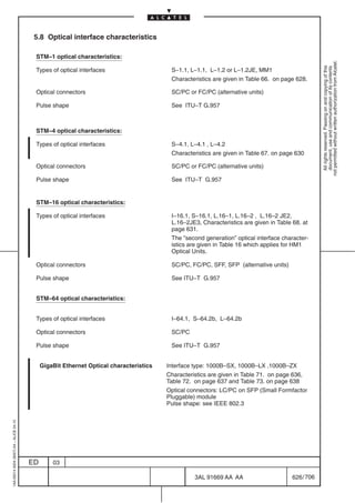
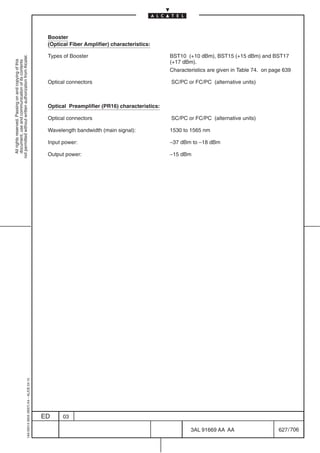
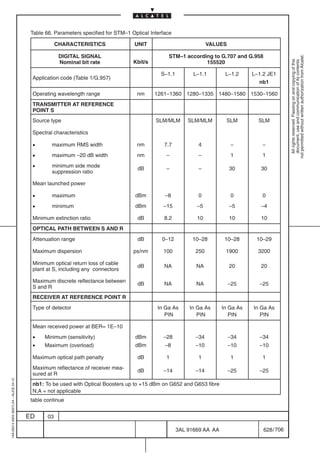
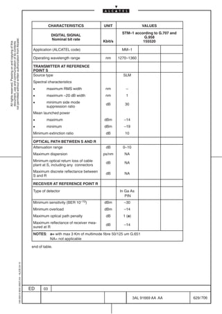
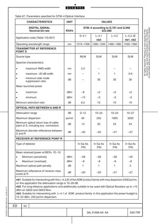
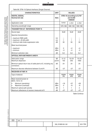
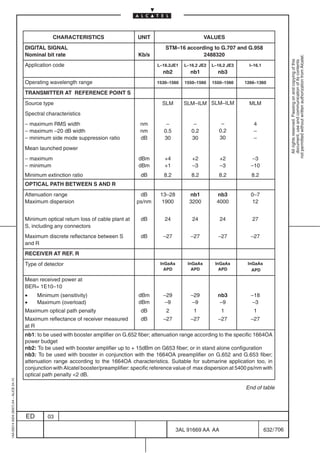
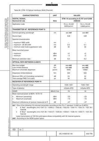
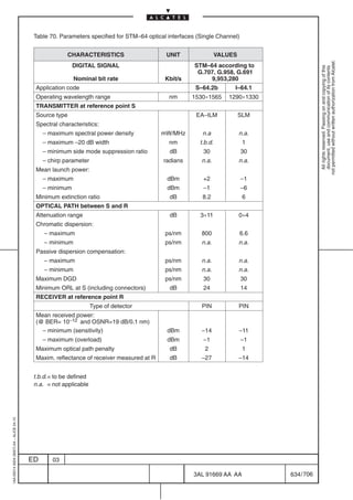
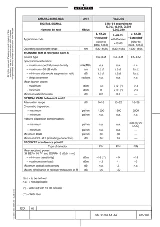
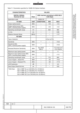
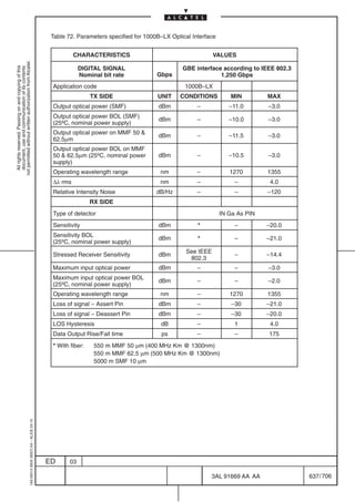
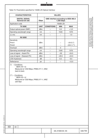
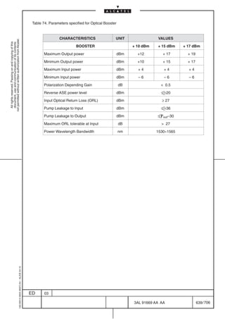
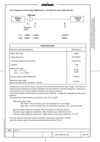
![5.8.2 Example of a link using 1660SM with L–64.2b “Extended”
The L–64.2B extended application described here below is suitable to cover span with attenuation range
(S–R) up to 28 dB, including optical path penalty (2dB). The performances of this application (max.
not permitted without written authorization from Alcatel.
attenuation range and max. chromatic dispersion) is between the ones of L64.2b and V64.2. Although it
All rights reserved. Passing on and copying of this
document, use and communication of its contents
is not part of standard ITU–T applications, it could be used for some customer specific cases.
The solution is based on usage of BW interfaces of 1660SM (“STM 64 PORT L– 64.2 B FC” card), DCU
(Optical Compensation Device), and booster.
Figure 300. below shows the network block diagram for implementing the application (parameters have
to be considered EOL):
Booster
Pin max.: +4
= 3.5/5 dB
DCU
ÏÏÏ
ÏÏÏÏÏÏ1660SM
L64.2b Port
ÏÏÏÏÏÏ ÏÏÏÏÏ
ÏÏÏÏÏ 20
ÏÏÏ
+10
ÏÏÏ ÏÏÏÏÏÏ
1660SM
L64.2b Port
ÏÏÏÏÏÏ
(Tx) (400ps/nm) (Rx)
ÏÏÏÏÏÏ
ÏÏÏÏÏÏ ÏÏÏÏÏ
ÏÏÏÏÏ
ÏÏÏ
Pin min.: –6
ÏÏÏÏÏÏ
ÏÏÏÏÏÏ
MPI–S MPI–R
Max: +3 Max: – 0.5 28 dBm
Min: 0 Min: –5
max+13dBm max–3dBm
min +10dBm min –18dBm
Figure 300. Example of a link using 1660SM with L–64.2b “Extended”
The L–64.2B Extended application is suitable for transmission with G.652, G.653 and G.655 fibers. Find
below main specifications:
– Wavelength: 1530–1565;
– Attenuation Range [S–R]: 16–28 dB (optical path penalty included – if needed, attenuation range
can be extended via optical attenuators);
– Maximum supported dispersion: 2000 ps/nm (achievable through 20km–400ps/nm dispersion
compensation DCU).
–See Table 75. for the relevant optical parameters
1AA 00014 0004 (9007) A4 – ALICE 04.10
ED 03
3AL 91669 AA AA 641 / 706
706](https://image.slidesharecdn.com/1660smtecr5-2ed03-100224044520-phpapp01/85/1660-S-M-Tec-R5-643-320.jpg)
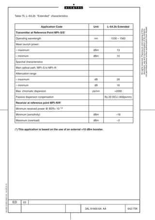
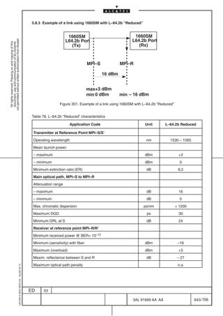

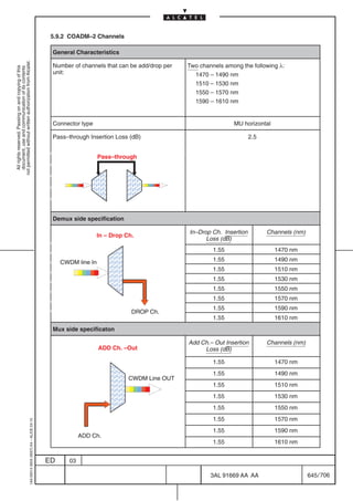
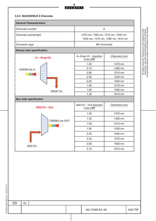
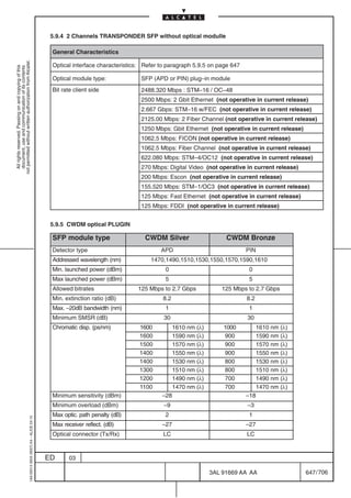
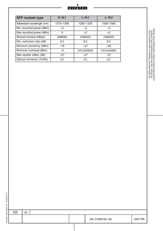


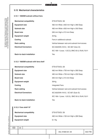


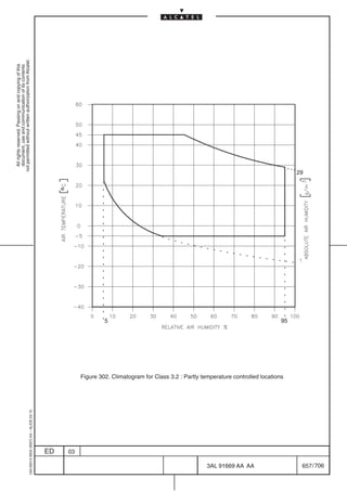

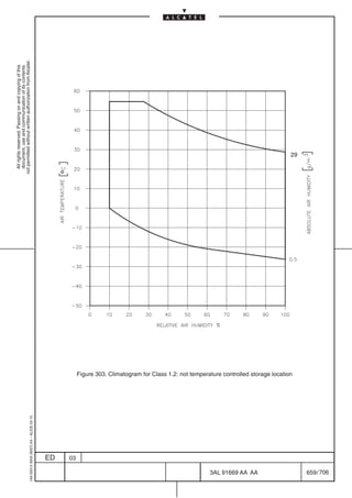

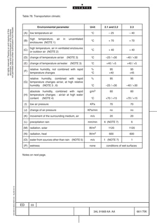


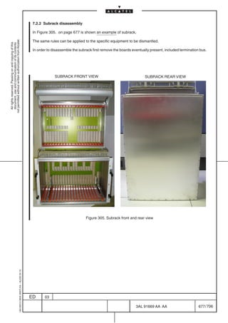
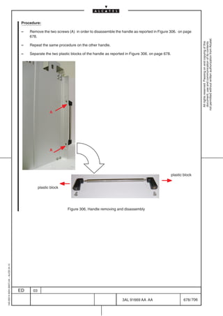
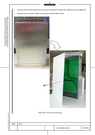
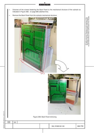
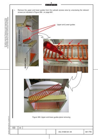
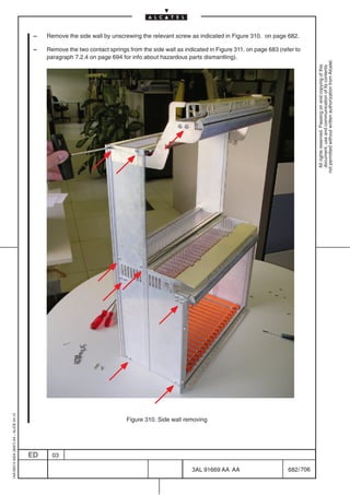
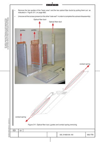
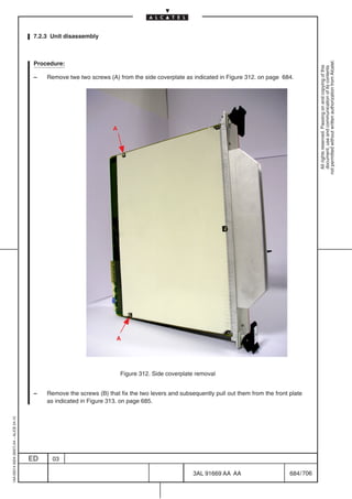
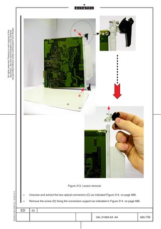
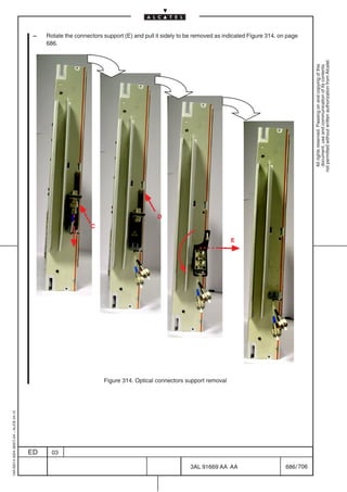
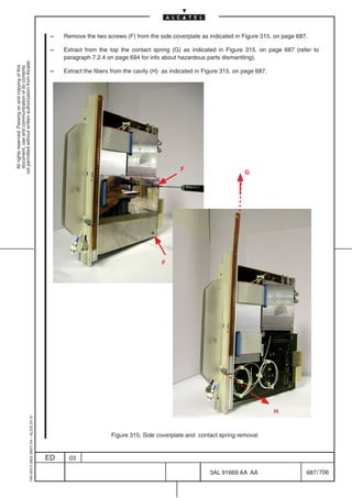
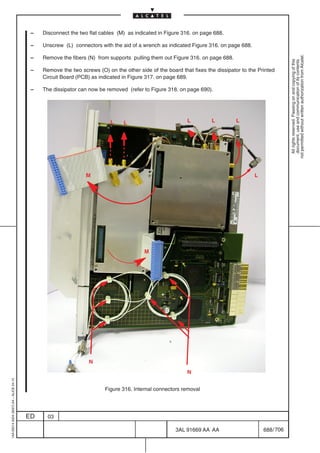
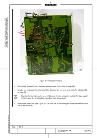
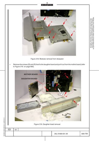
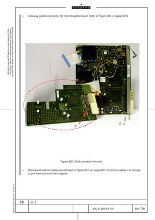
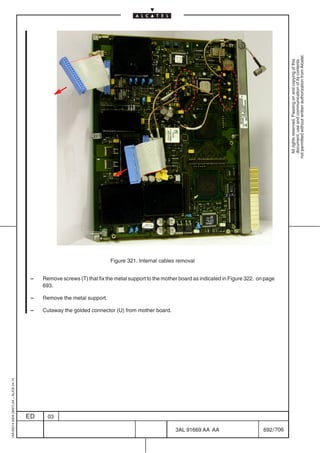
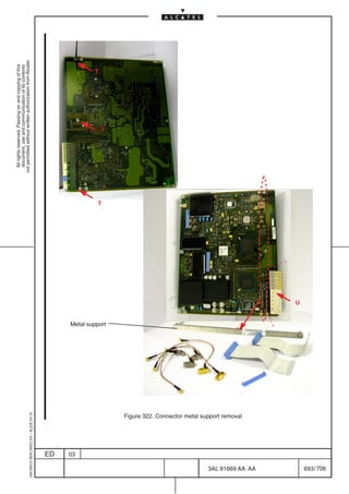


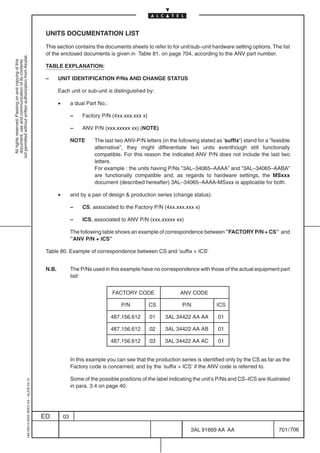

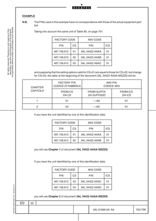
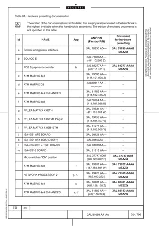
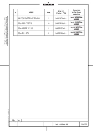


![Dicas De Configuração S D H Lucent A D M[1]](https://cdn.slidesharecdn.com/ss_thumbnails/dicasdeconfiguraosdhlucentadm1-100224044502-phpapp02-thumbnail.jpg?width=640&height=640&fit=bounds)


