This document is an operator's handbook that provides information about Alcatel's METRO OMSN products. It includes safety norms and labels, describes the structure and purpose of the handbook, and discusses Alcatel's customer documentation processes. The handbook covers Alcatel's 1640FOX, 1650SMC, 1660SM, and 1660SM product lines and is intended to instruct operators on the proper use of these STM-1/4 and STM-16/64 multiservice metro nodes.


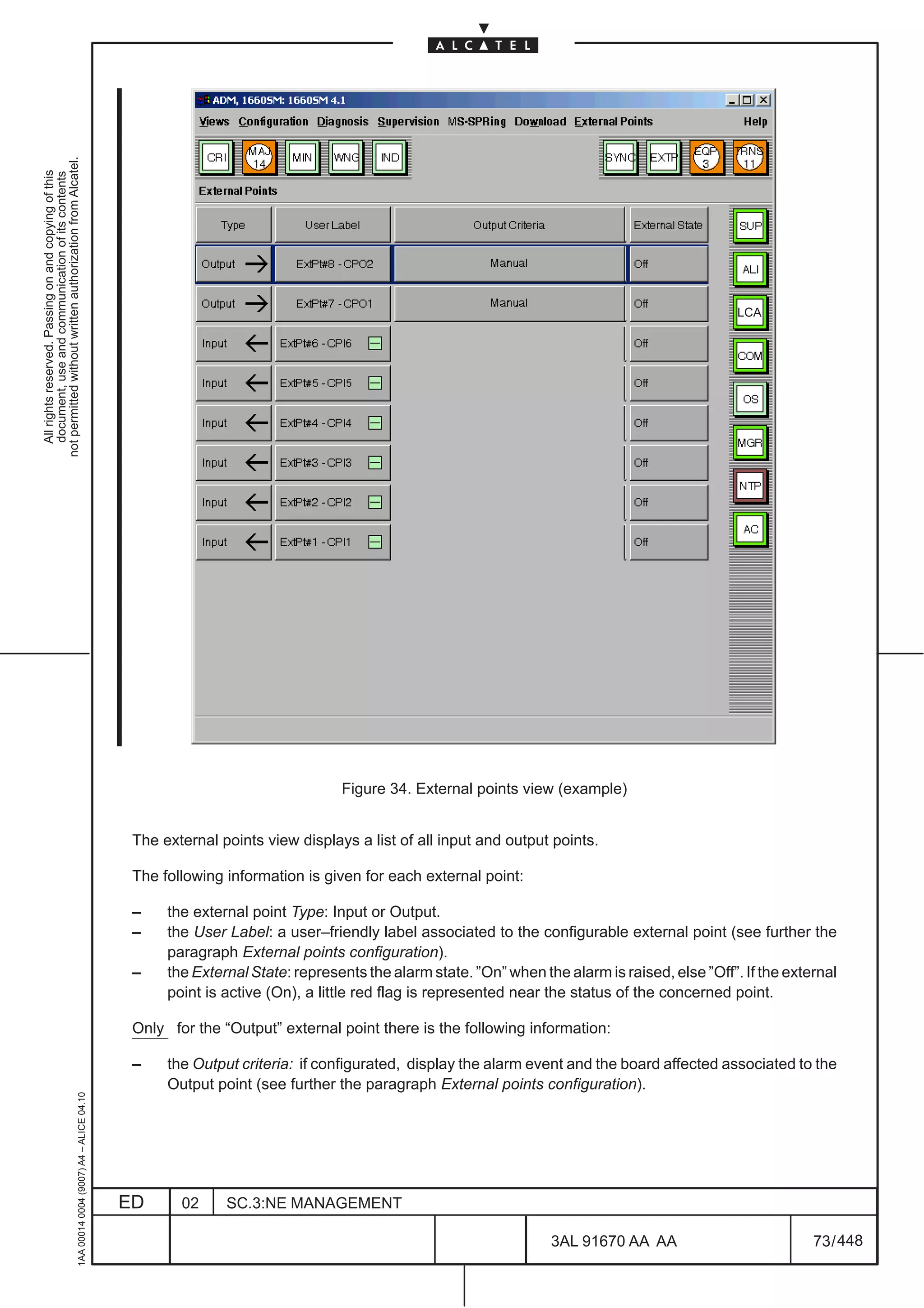
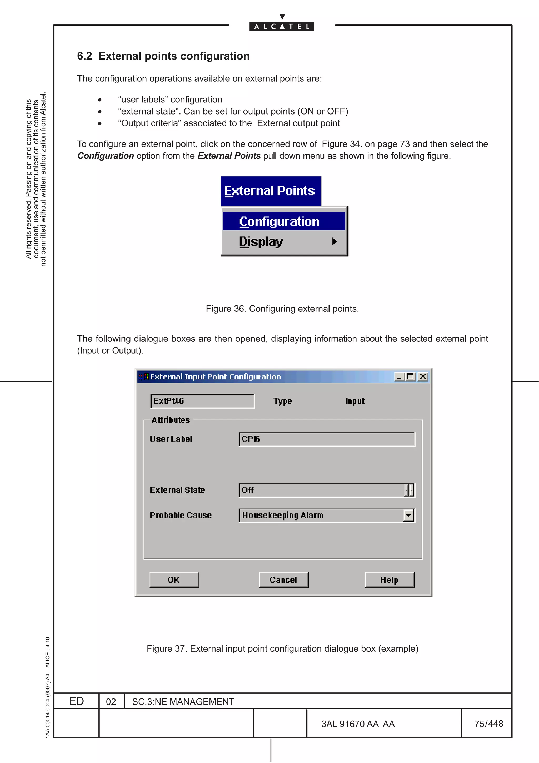
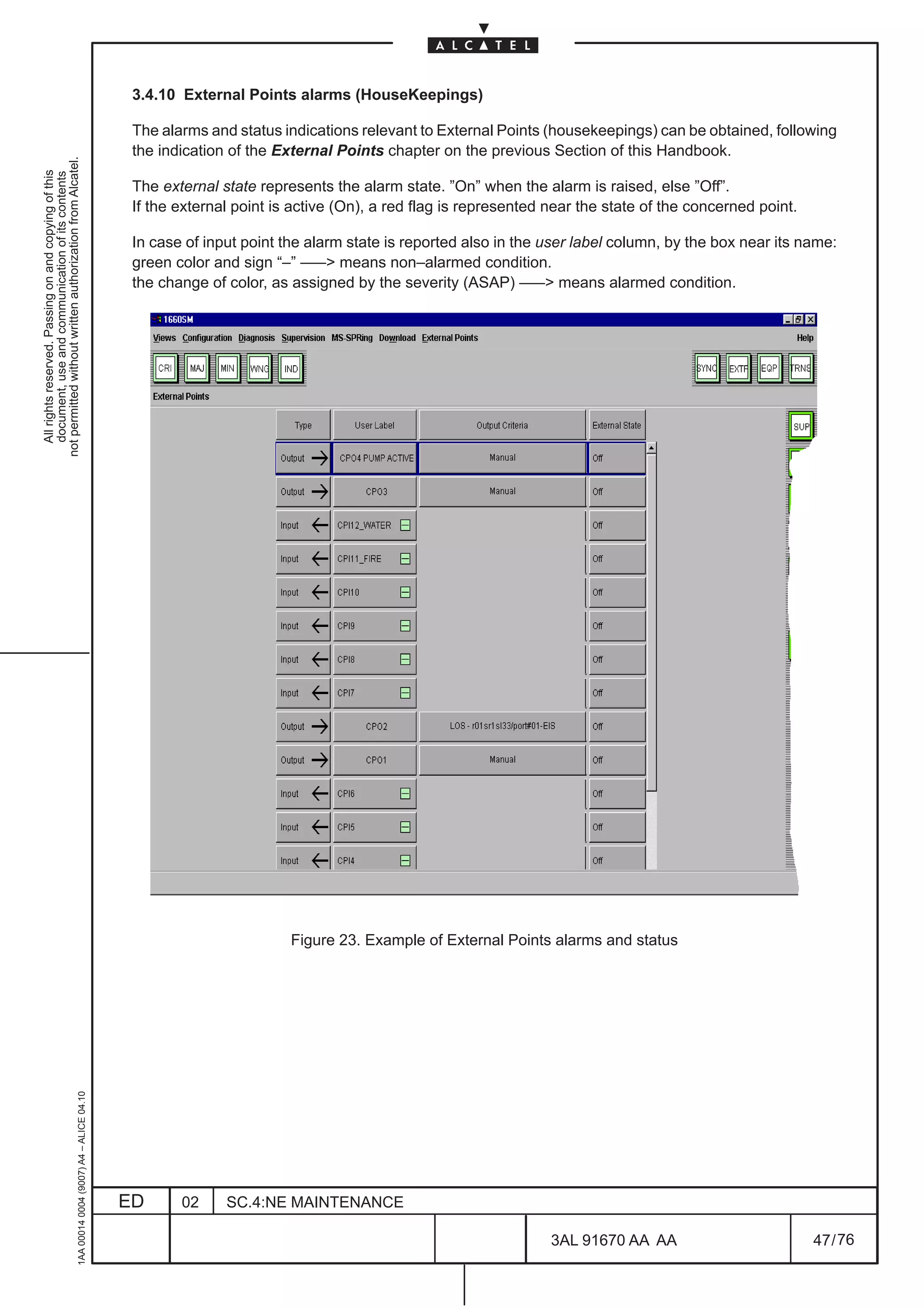
![Opening the dialog the current state of the selected External Point is shown.
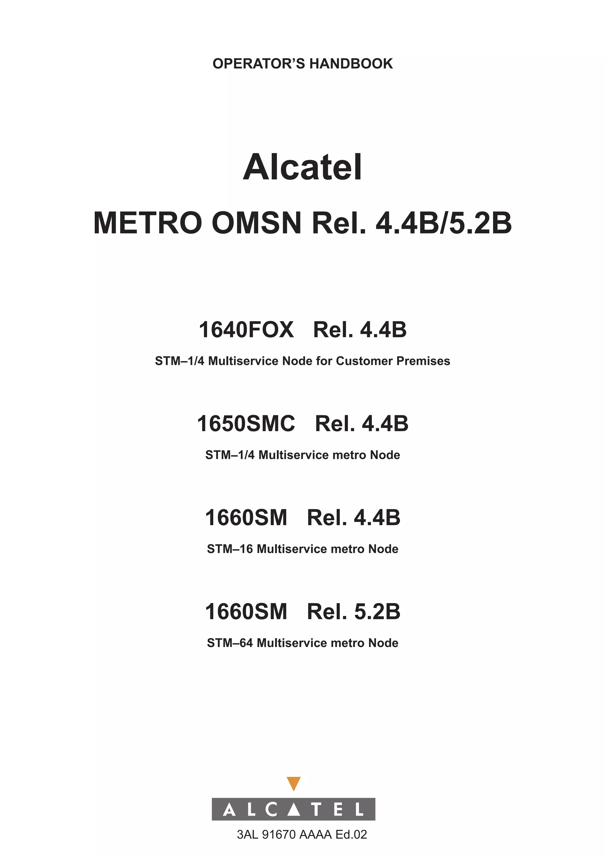
[1] External Input Point Configuration
not permitted without written authorization from Alcatel.
• Type: In the field the name of the involved Input point is displayed (e.g. ExtP#8 in Figure 37. )
All rights reserved. Passing on and copying of this
document, use and communication of its contents
• User Label: this field can be filled by the user with a Label that indicate the associated event
that must be taken under check (for example presences of water or fire in the room where the
Equipment is placed)
• External State: this field is set to off and can’t be changed by the operator
• Probable Cause: this field is set to housekeeping and can’t be changed by the operator
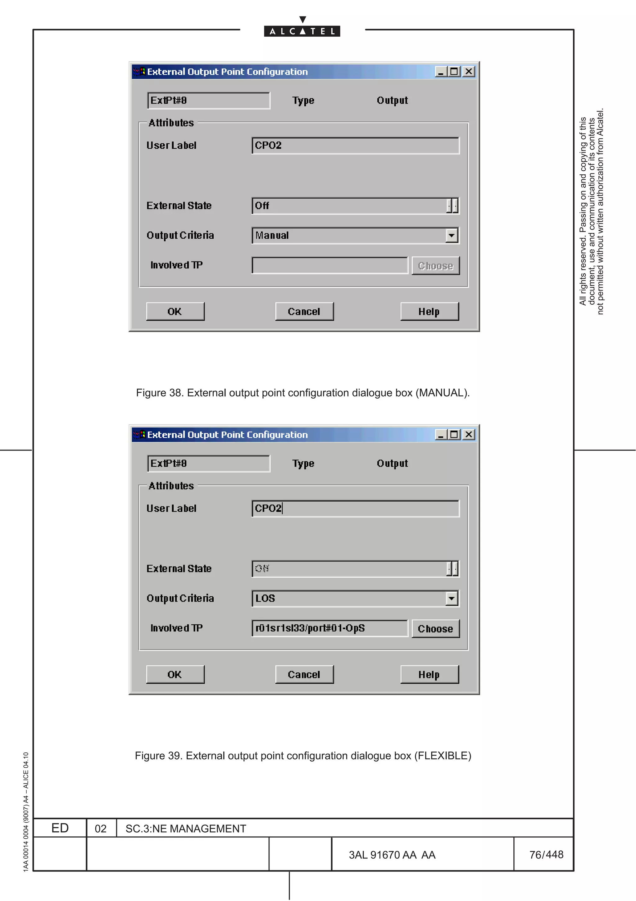
[2] External Output Point Configuration
• Type: In the field the name of the involved Output point is displayed (e.g. ExtP#8 in Figure 38. )
• User Label: this field can be filled by the user with a Label that indicate the alarm detected or
the action that must be executed if a specific event occur (for example a “Pump” activation when
water is present in the room where the equipment is placed)
• External State: can be set to “on” (alarm) or “off” (non alarm) only if “Manual” option has been
selected in the “Output Criteria” field.
• Output Criteria can be configured as :
– Manual (forced). The output contact is set in a fixed way , not depending on a particular
event.
For example the output contact could be used to “Manually” activate a pump to drain water
from the room where the equipment is placed ; in this case is also necessary to set the
option “On” in the field “External State”.
– Flexible. It is possible to define from CT the couple event/CPO#, where the event is
chosen between a set of Output Criteria (LOS, RDI and LOF) and specifies the STM–N
interface which the Output Criteria refers to by clicking on Choose button; subsequently
the TP search dialog box will be opened.
When the configuration of the external point is completed, click on the OK push button to validate the
choice and close the dialogue box. The Cancel push button cancels the configuration and closes the
dialogue box.
1AA 00014 0004 (9007) A4 – ALICE 04.10
ED 02 SC.3:NE MANAGEMENT
3AL 91670 AA AA 77 / 448
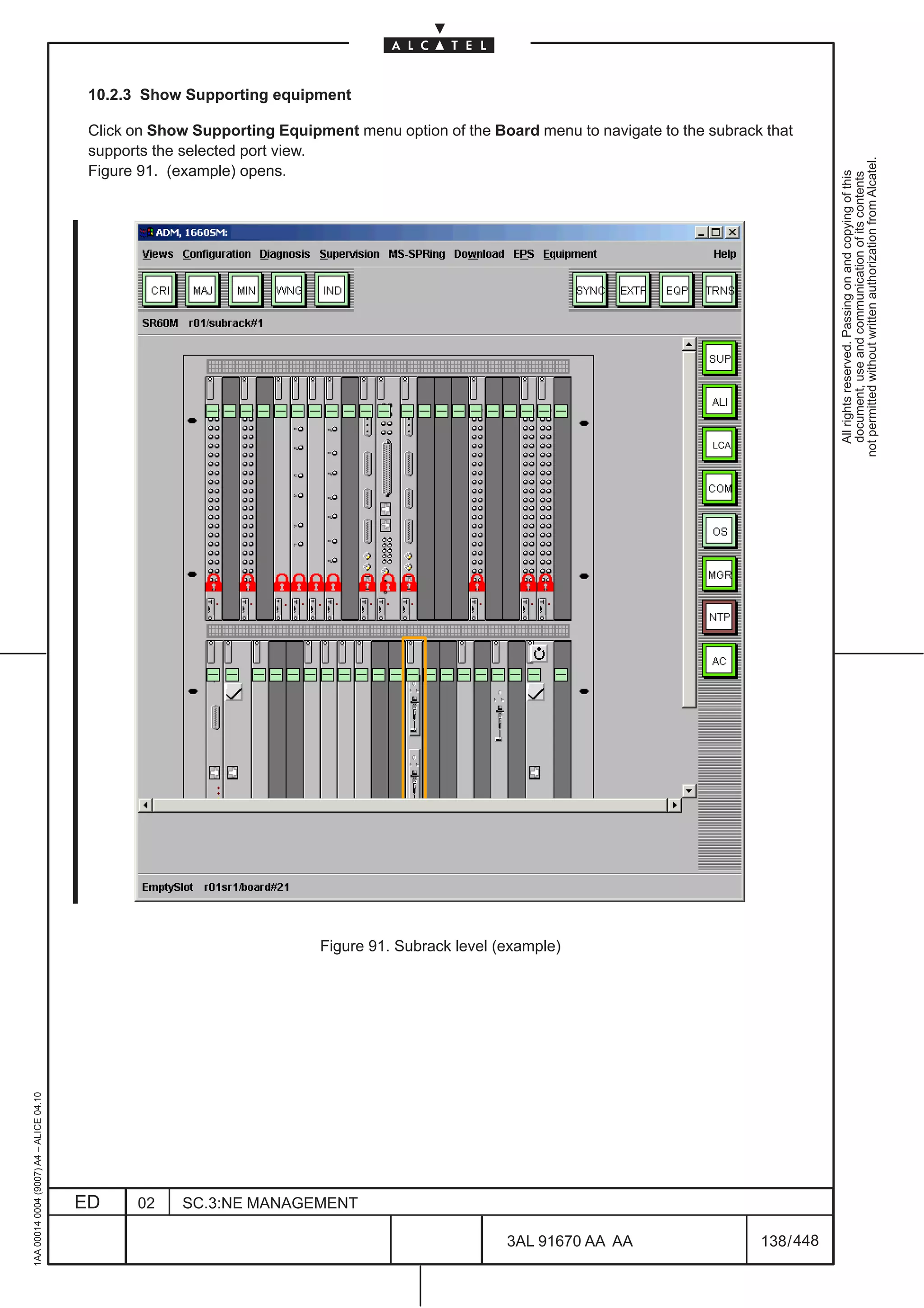
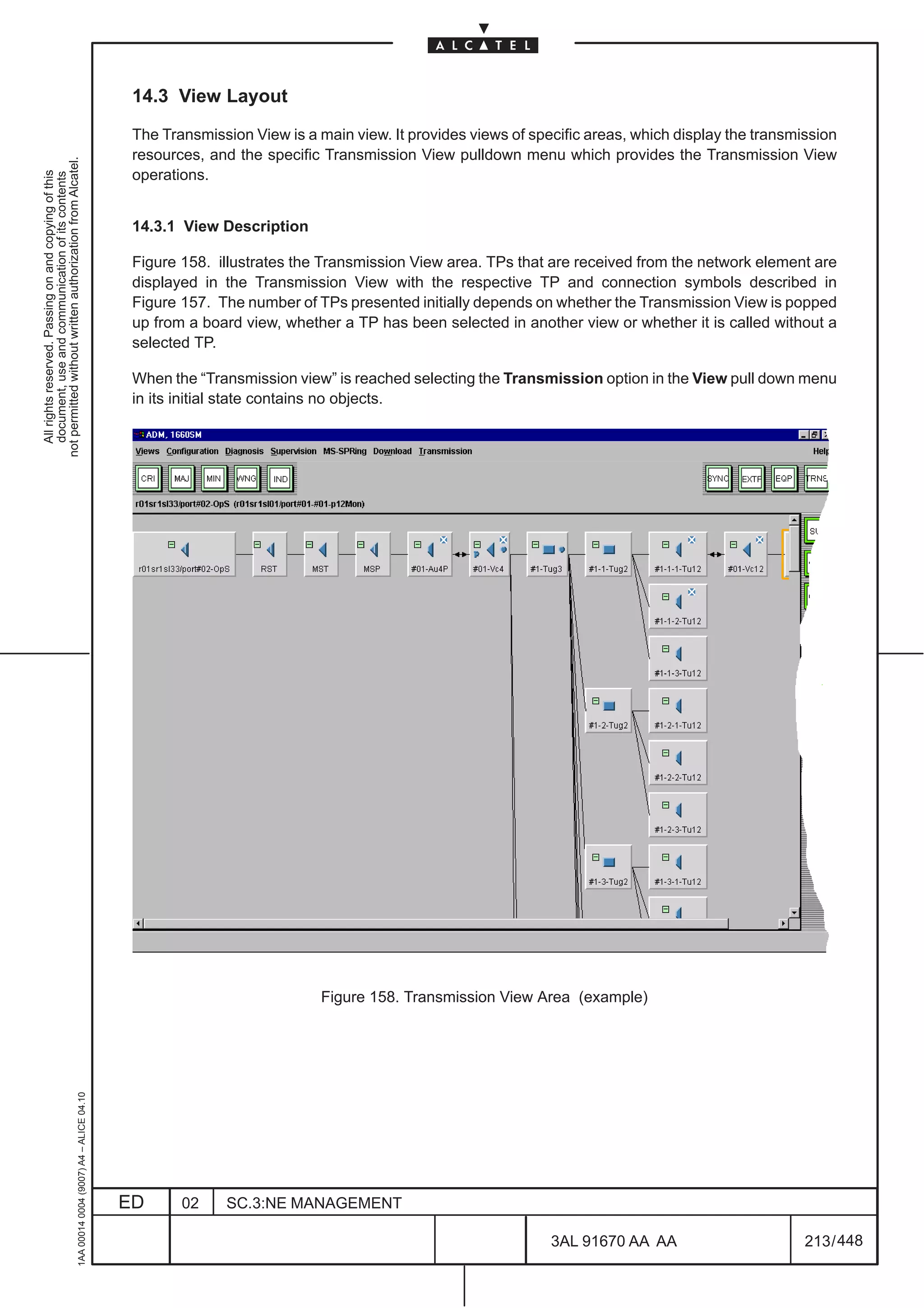
448](https://image.slidesharecdn.com/1660smoperr4-452b-100224044515-phpapp01/75/1660-S-M-Oper-R4-125-2048.jpg)

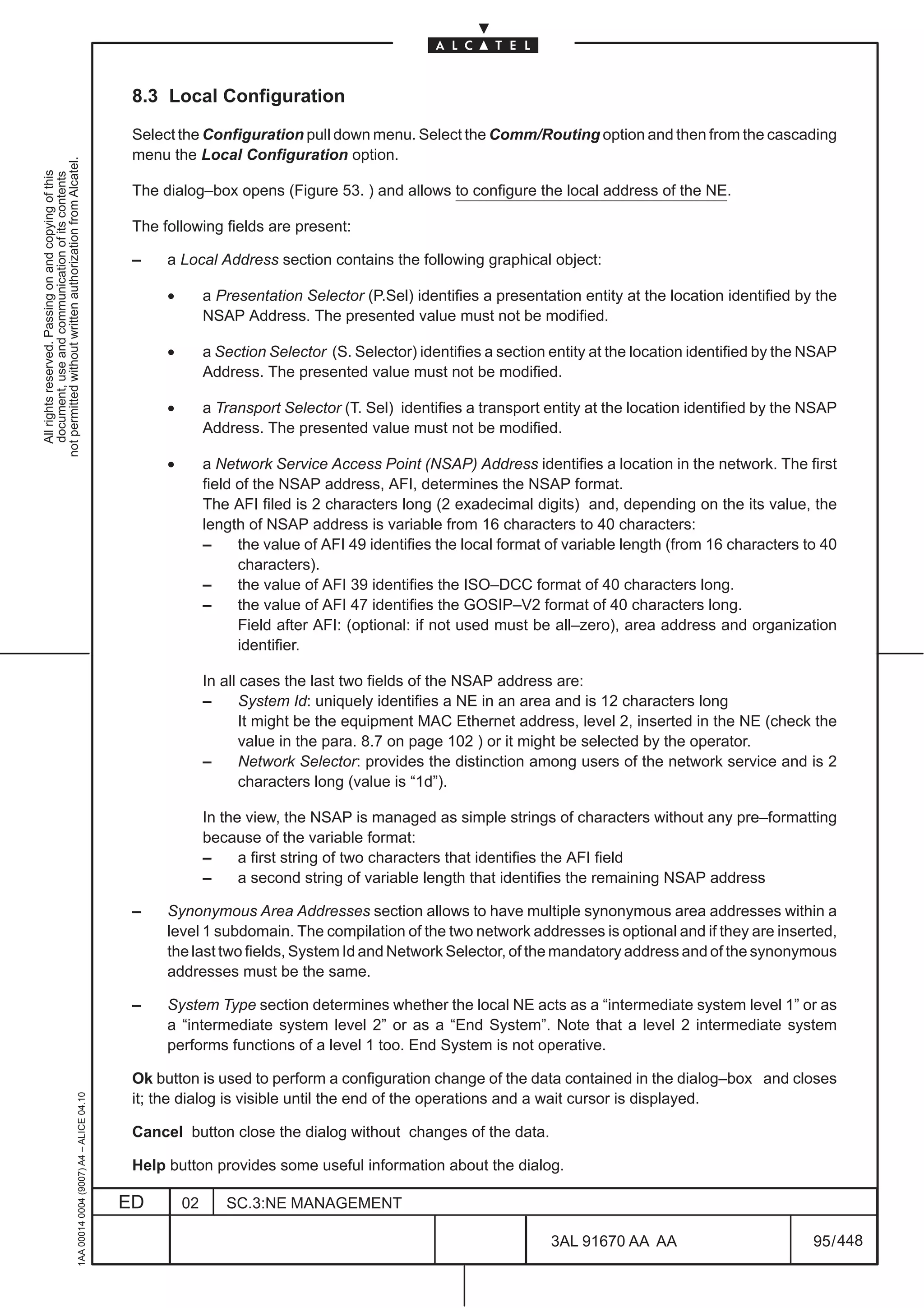
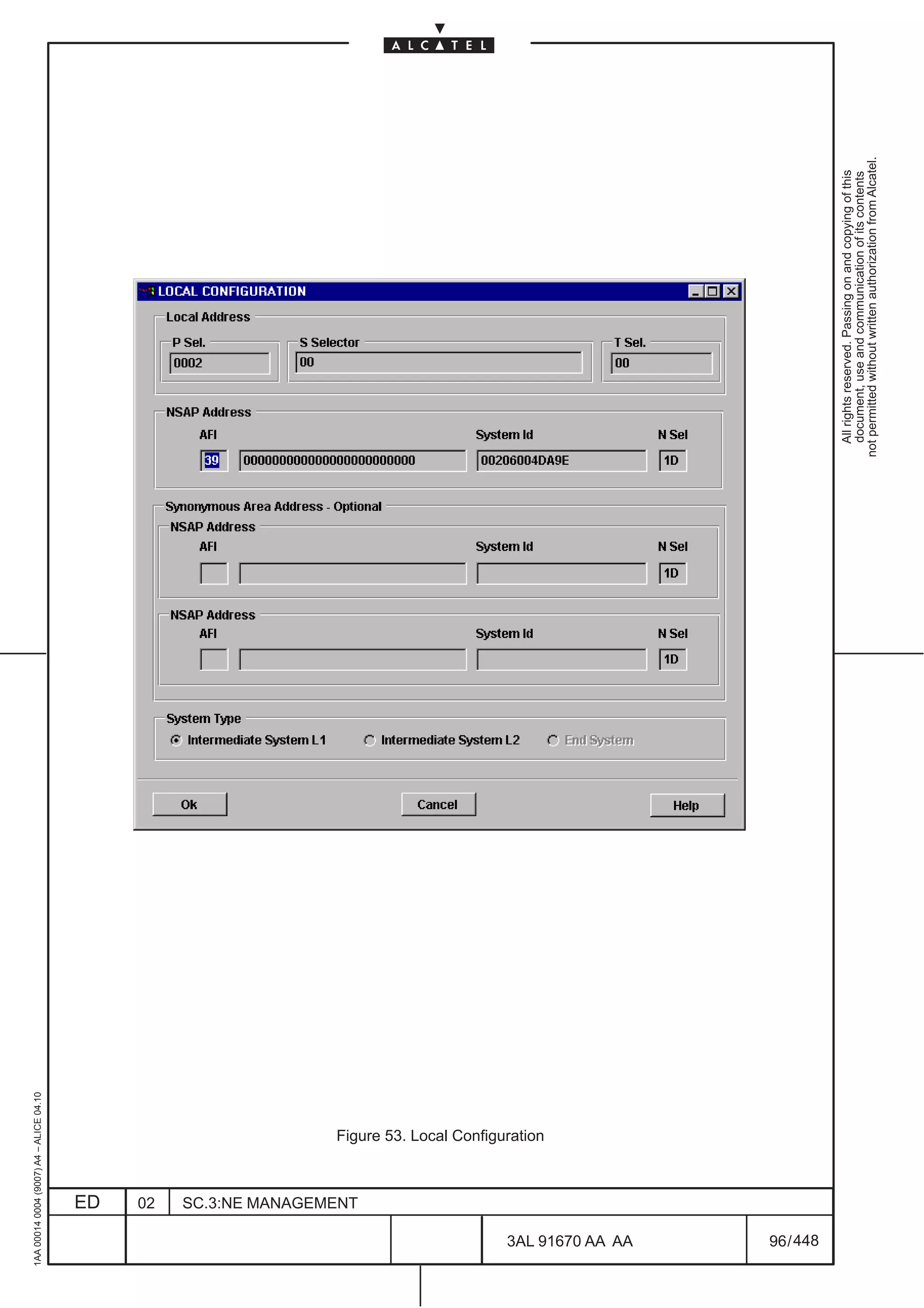
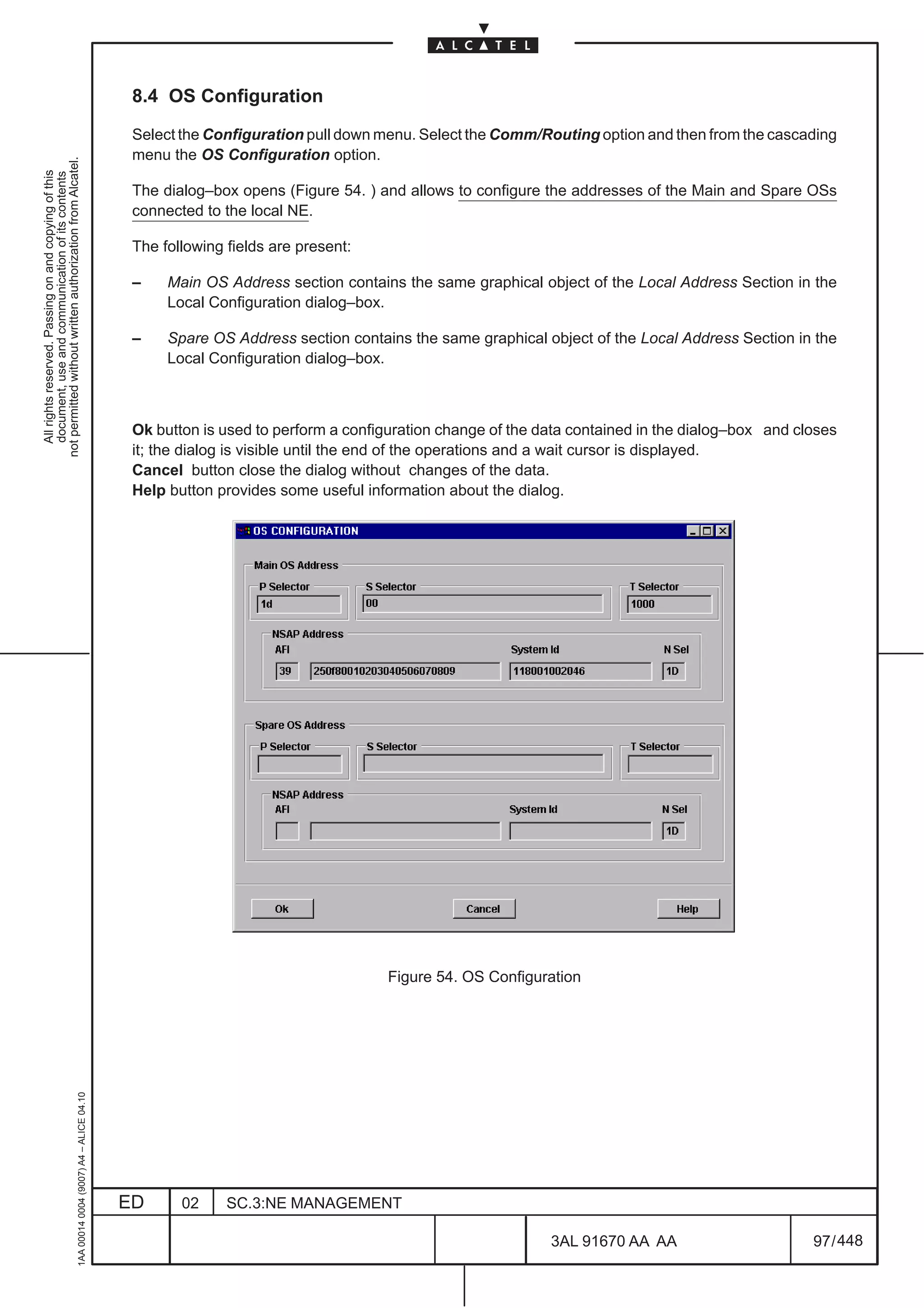
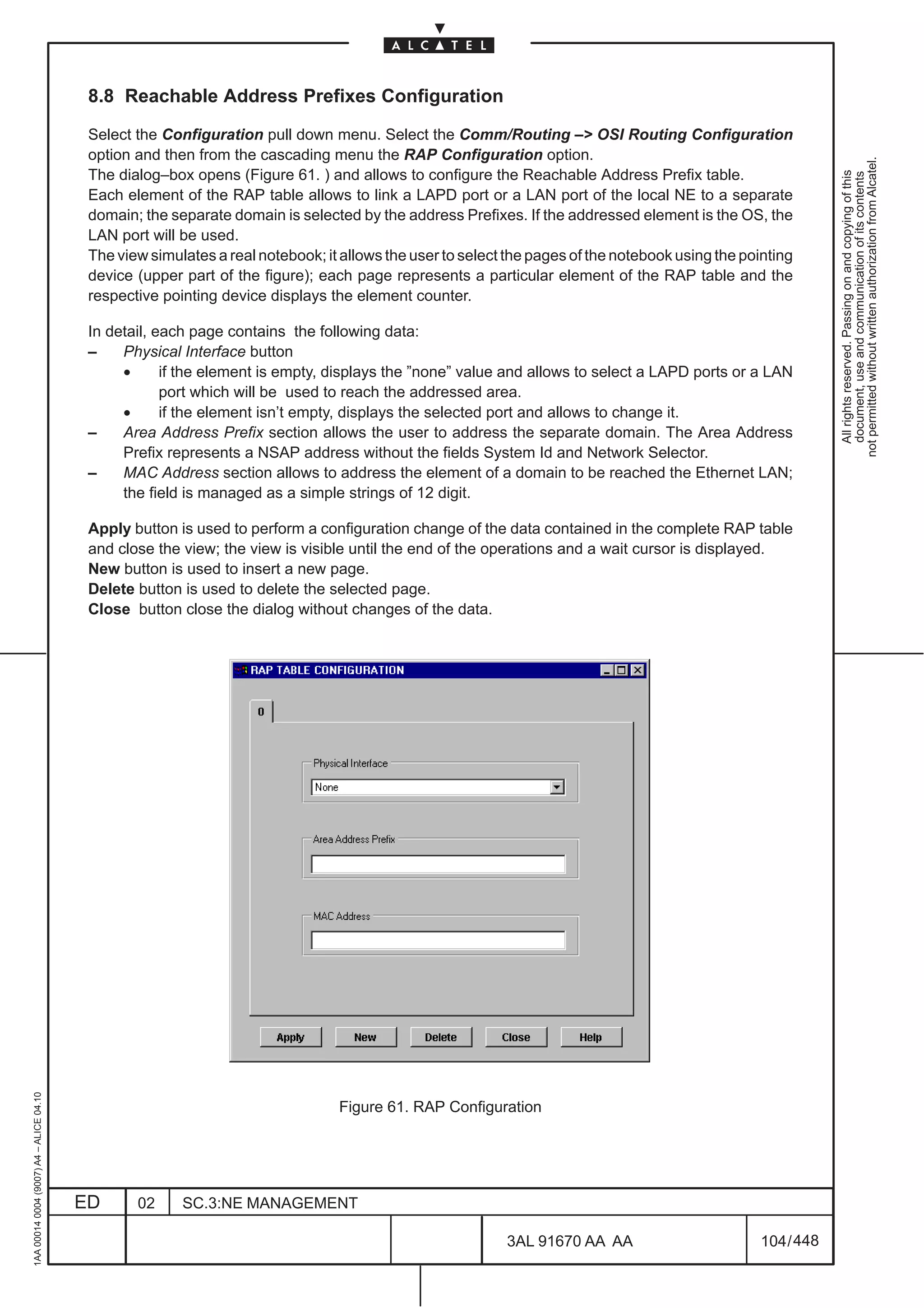
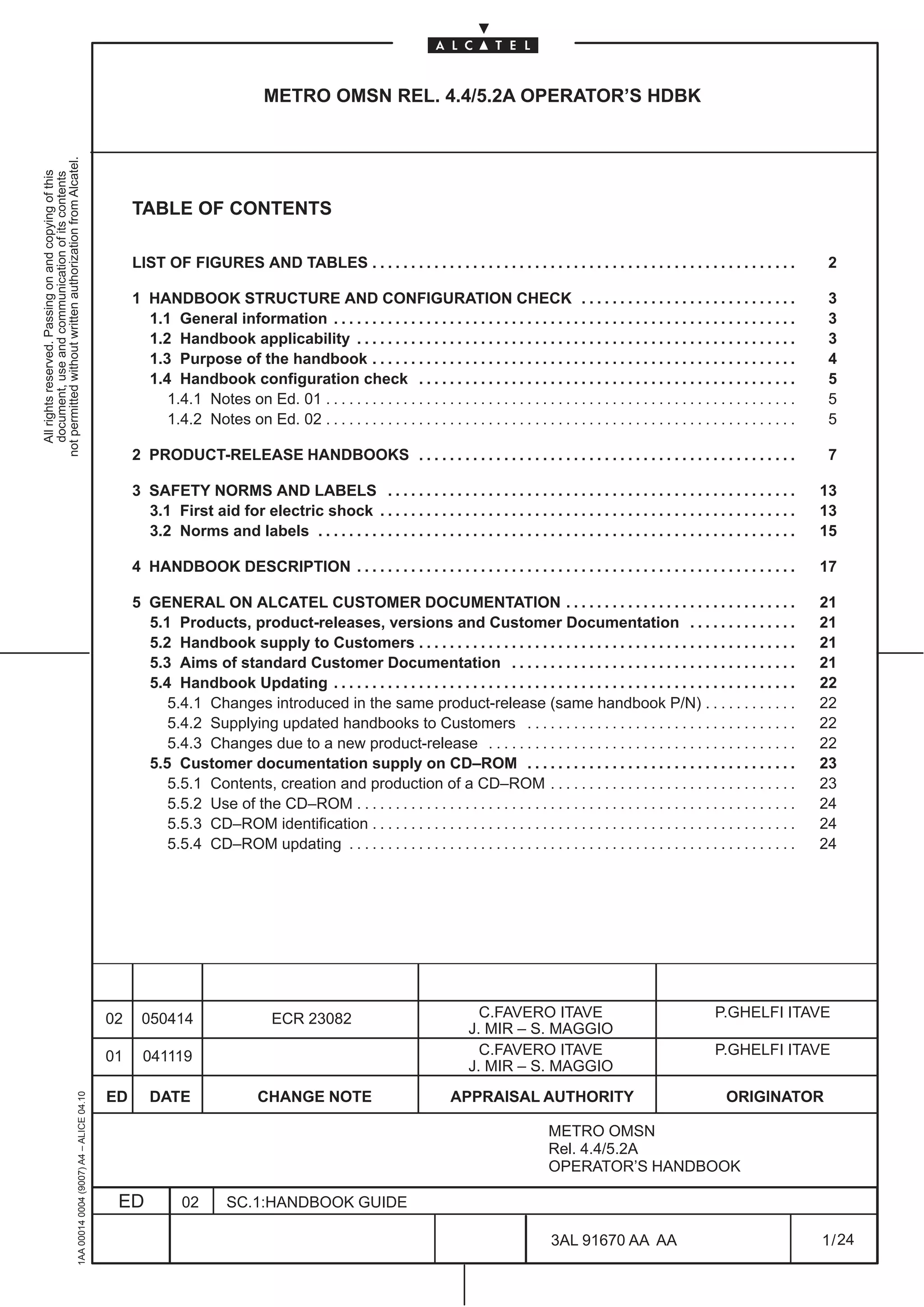
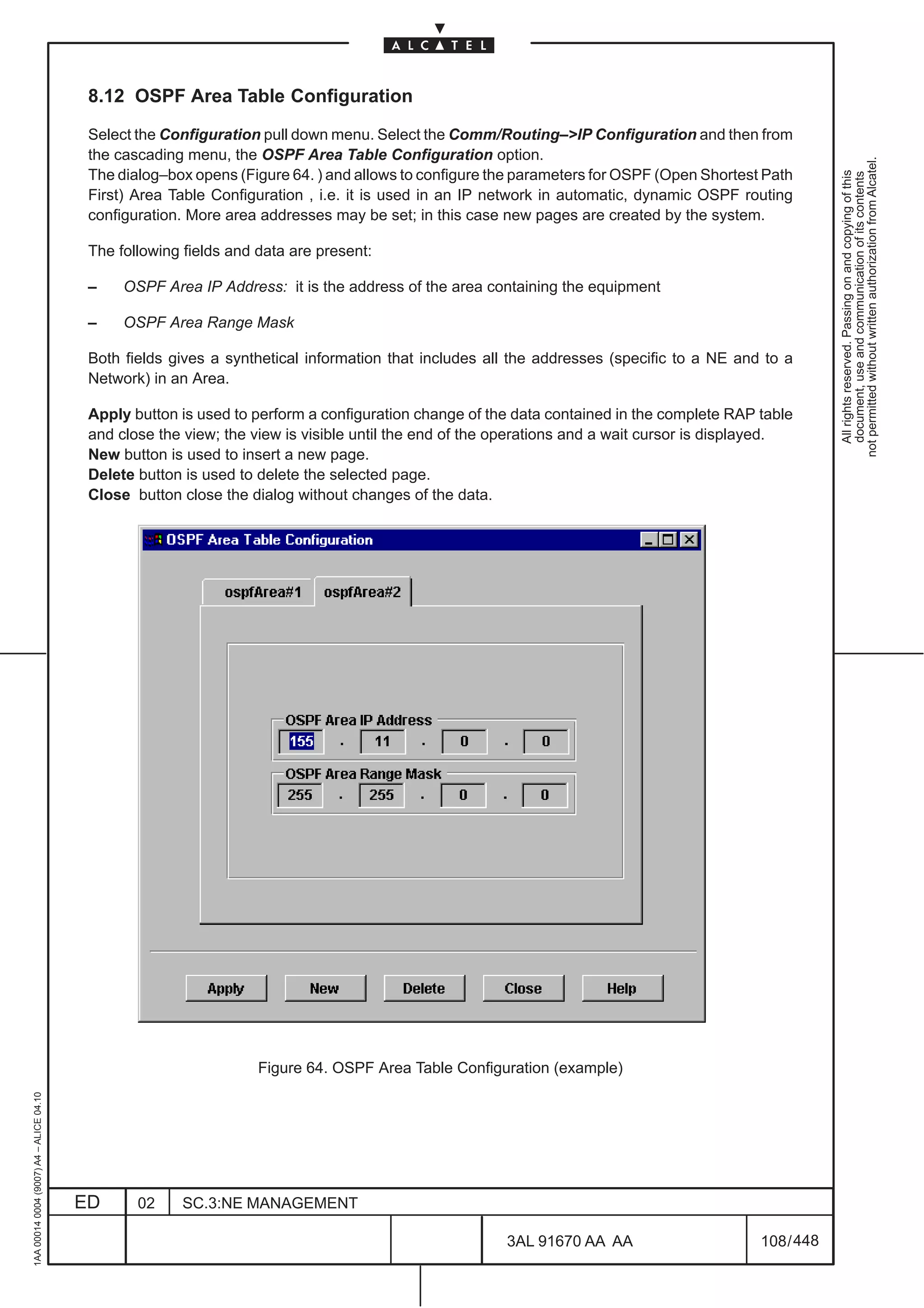
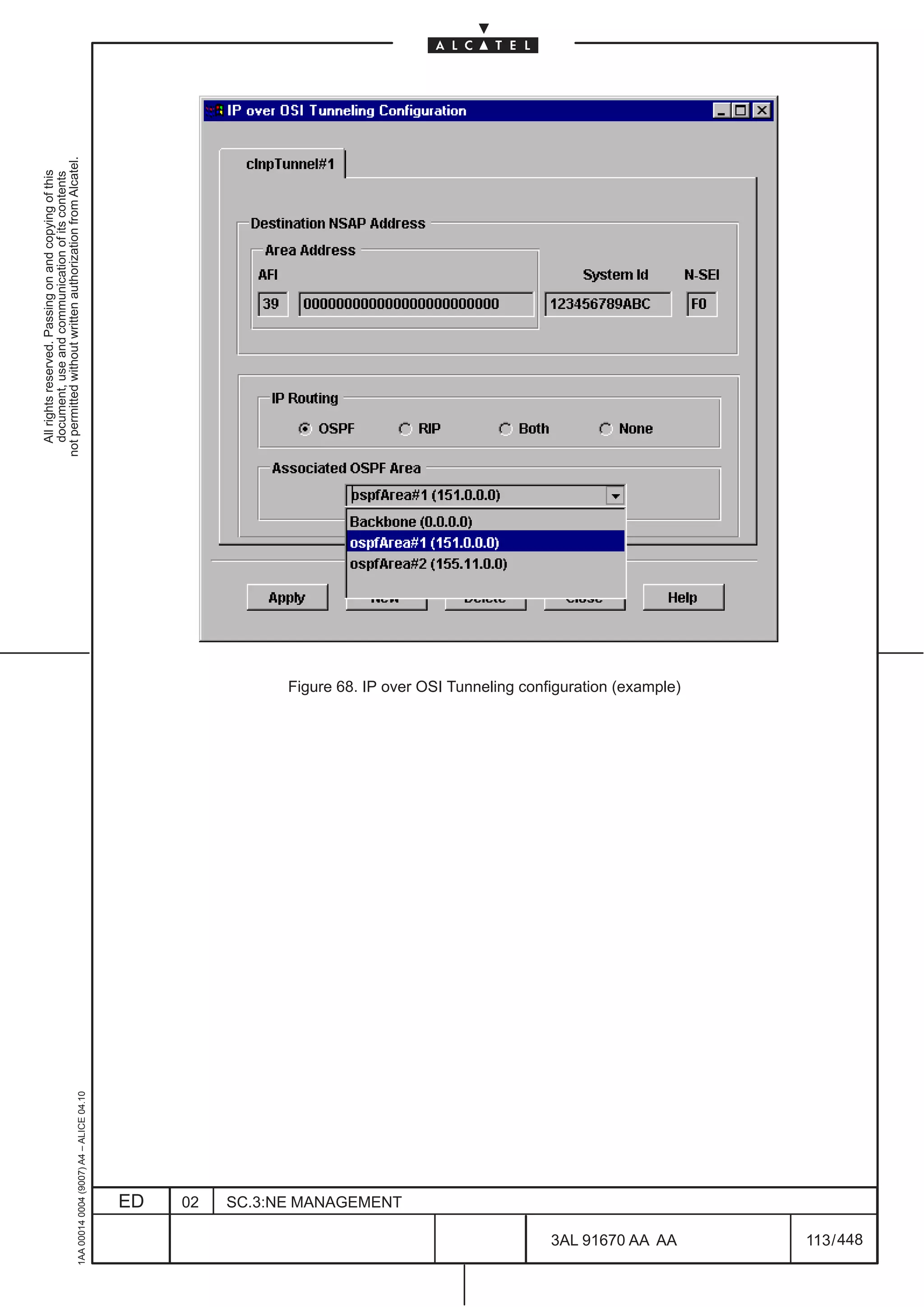
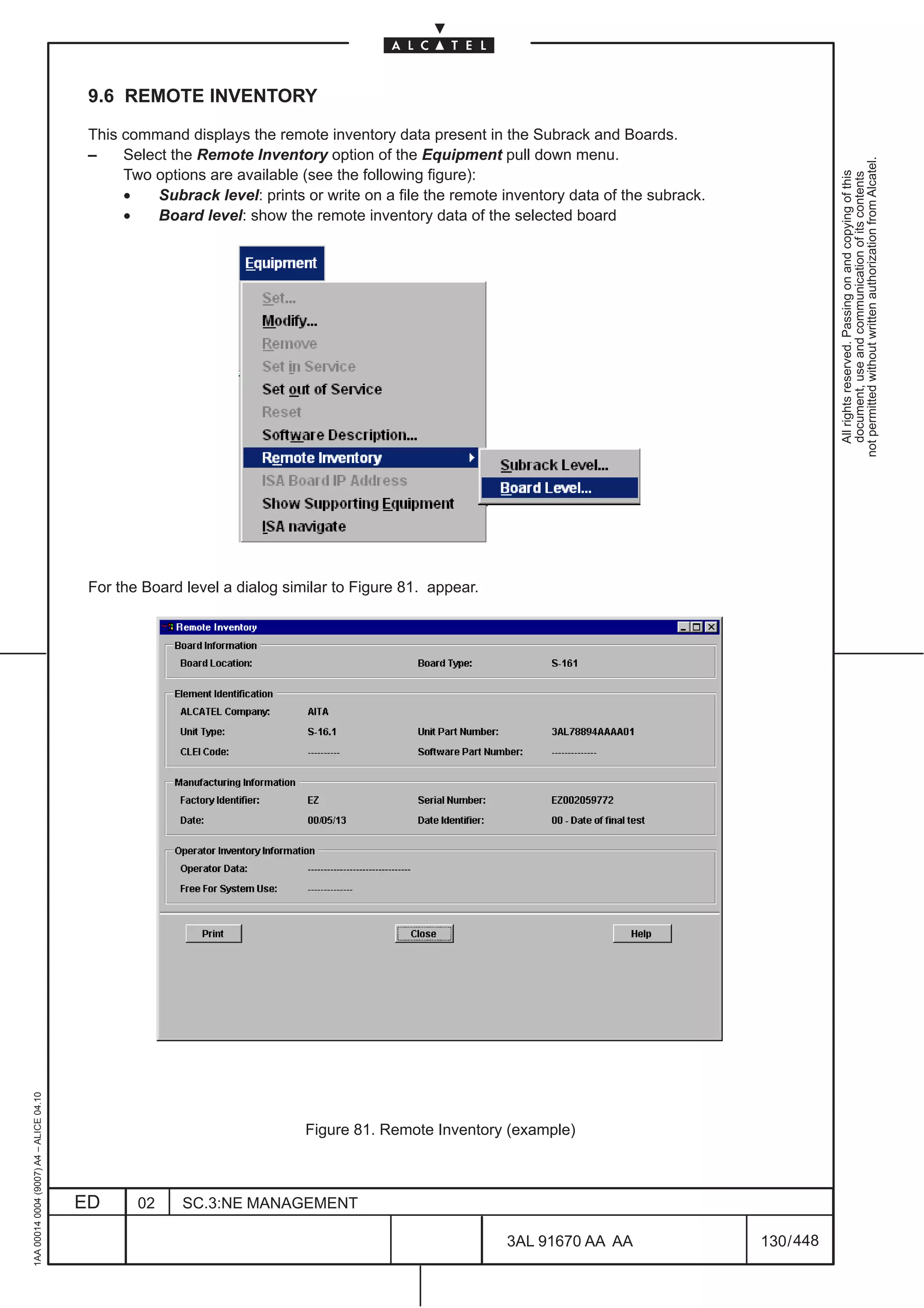
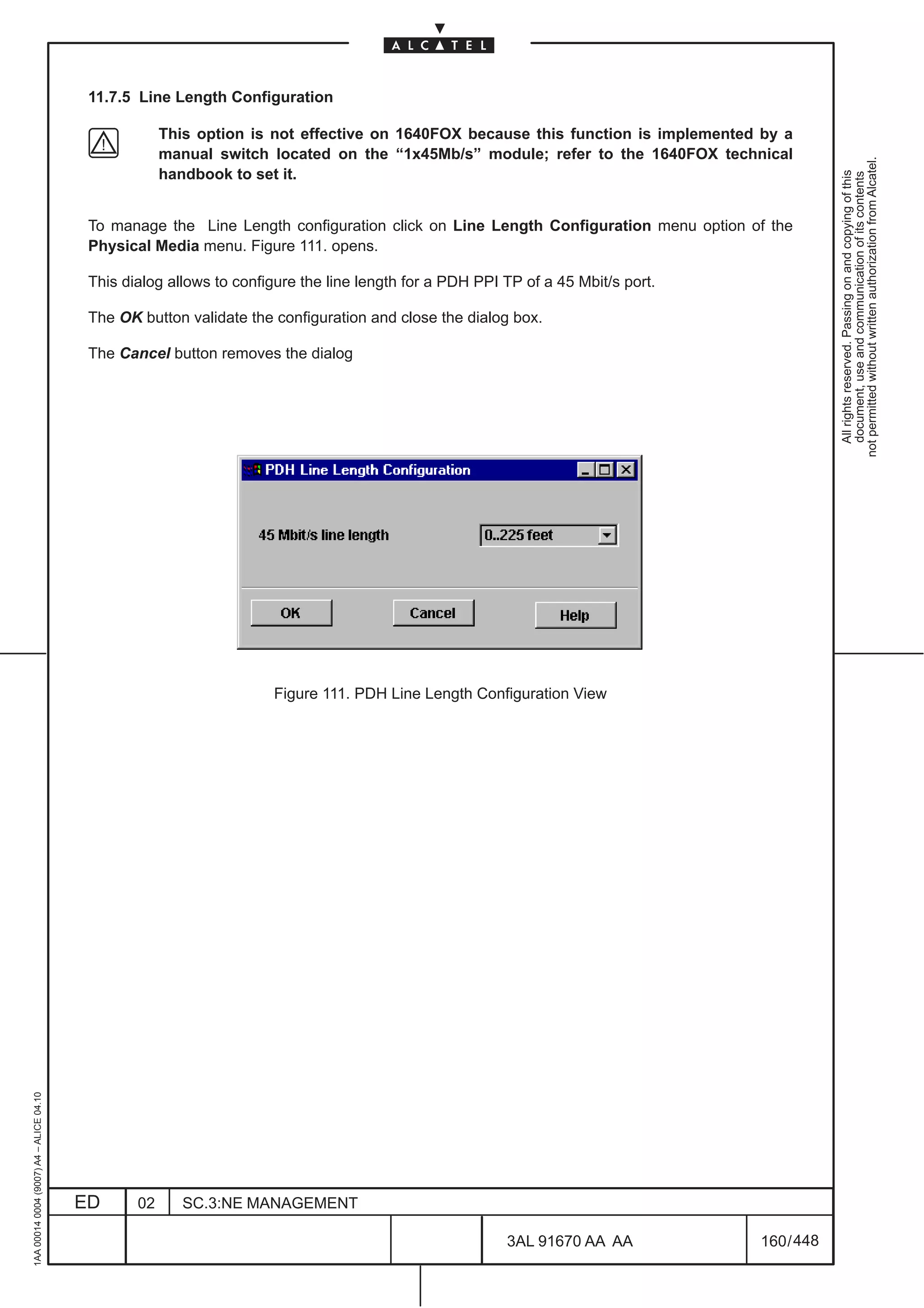
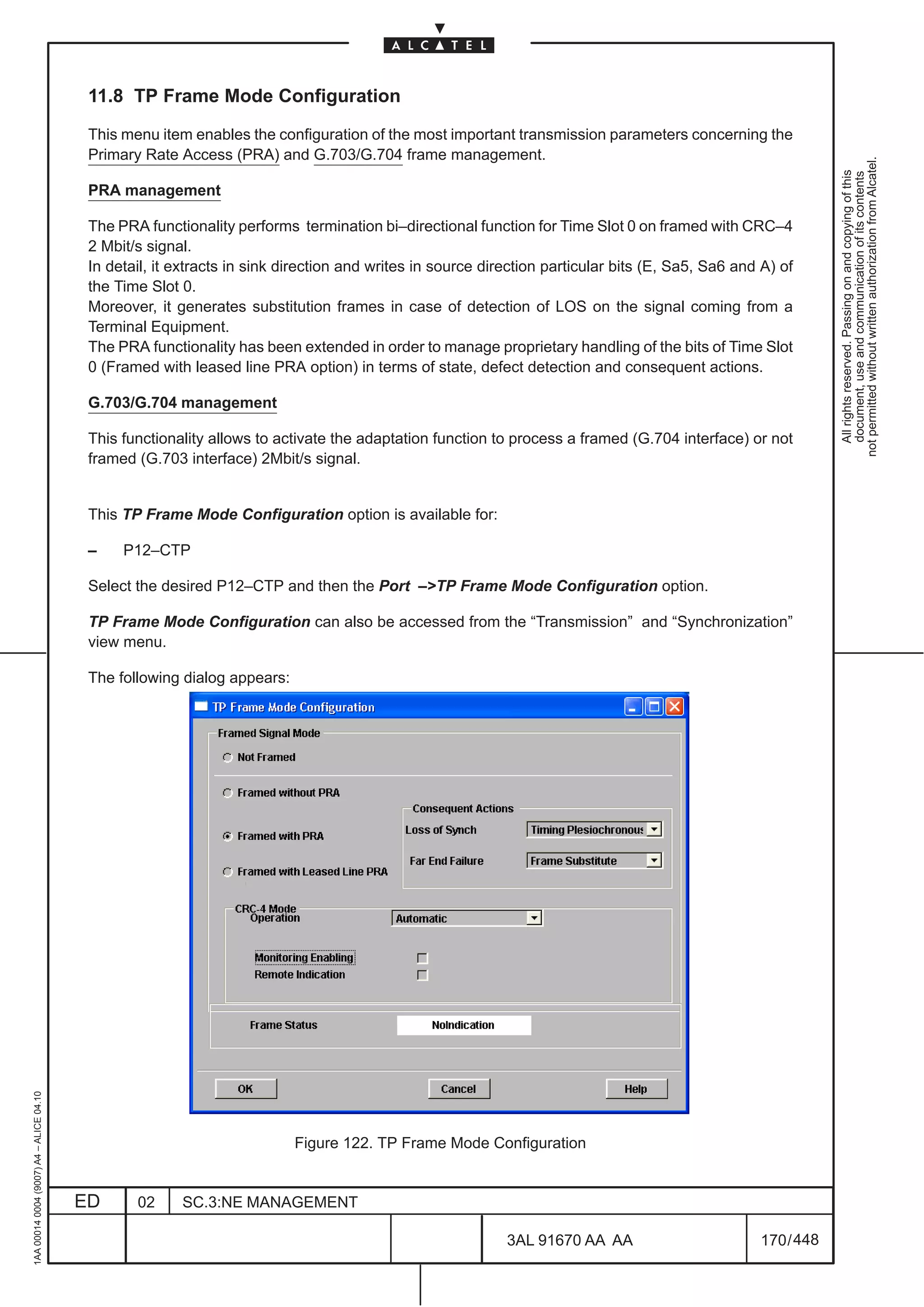
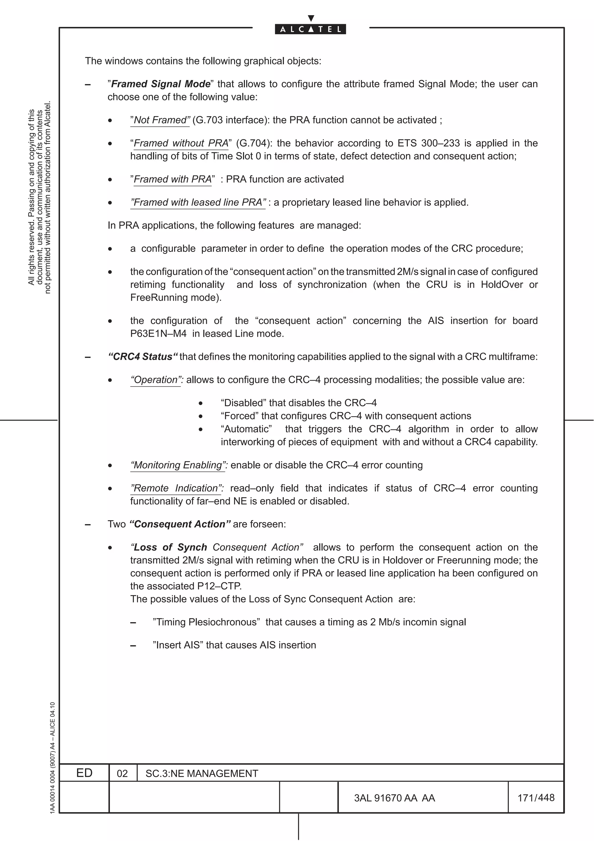
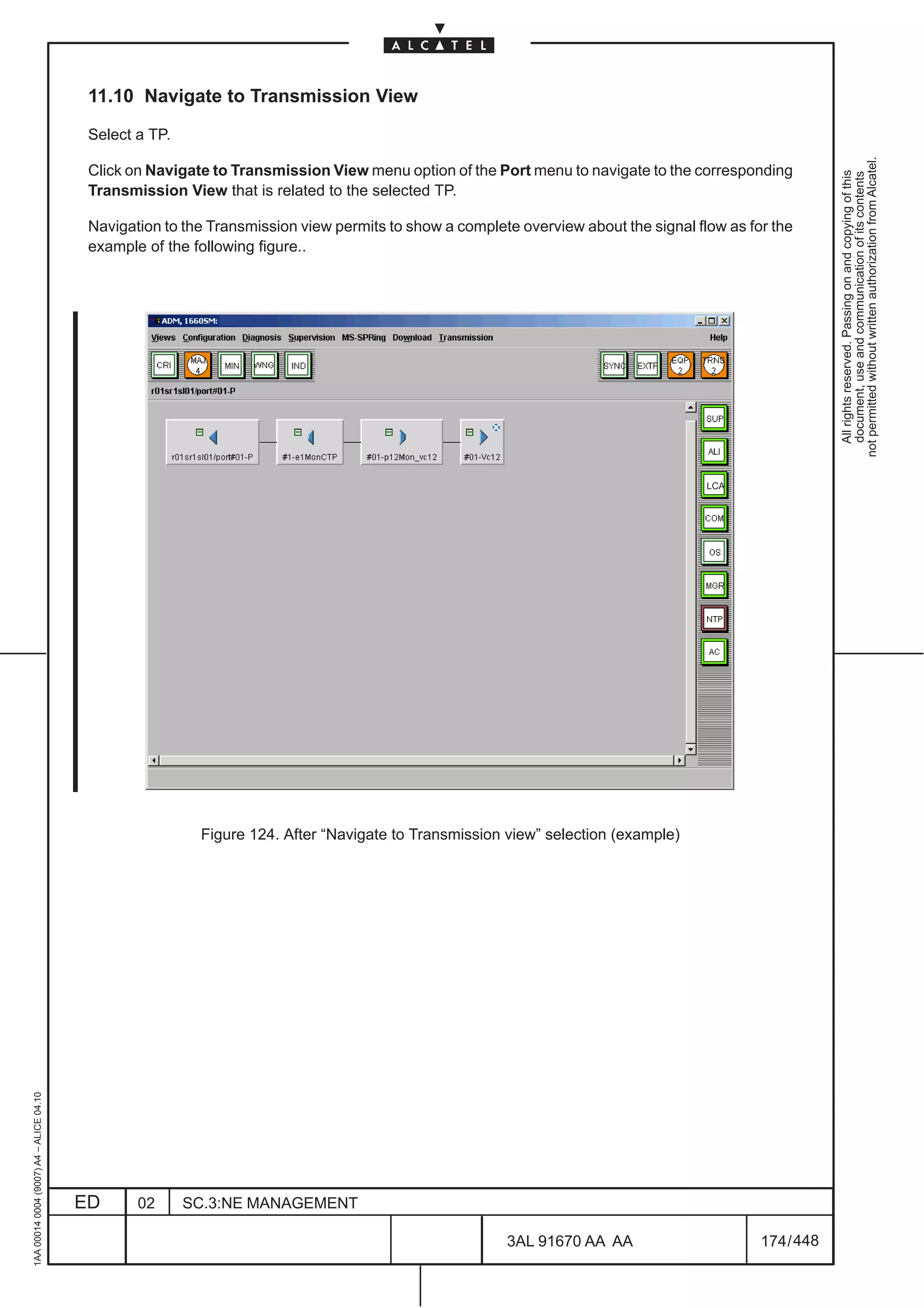
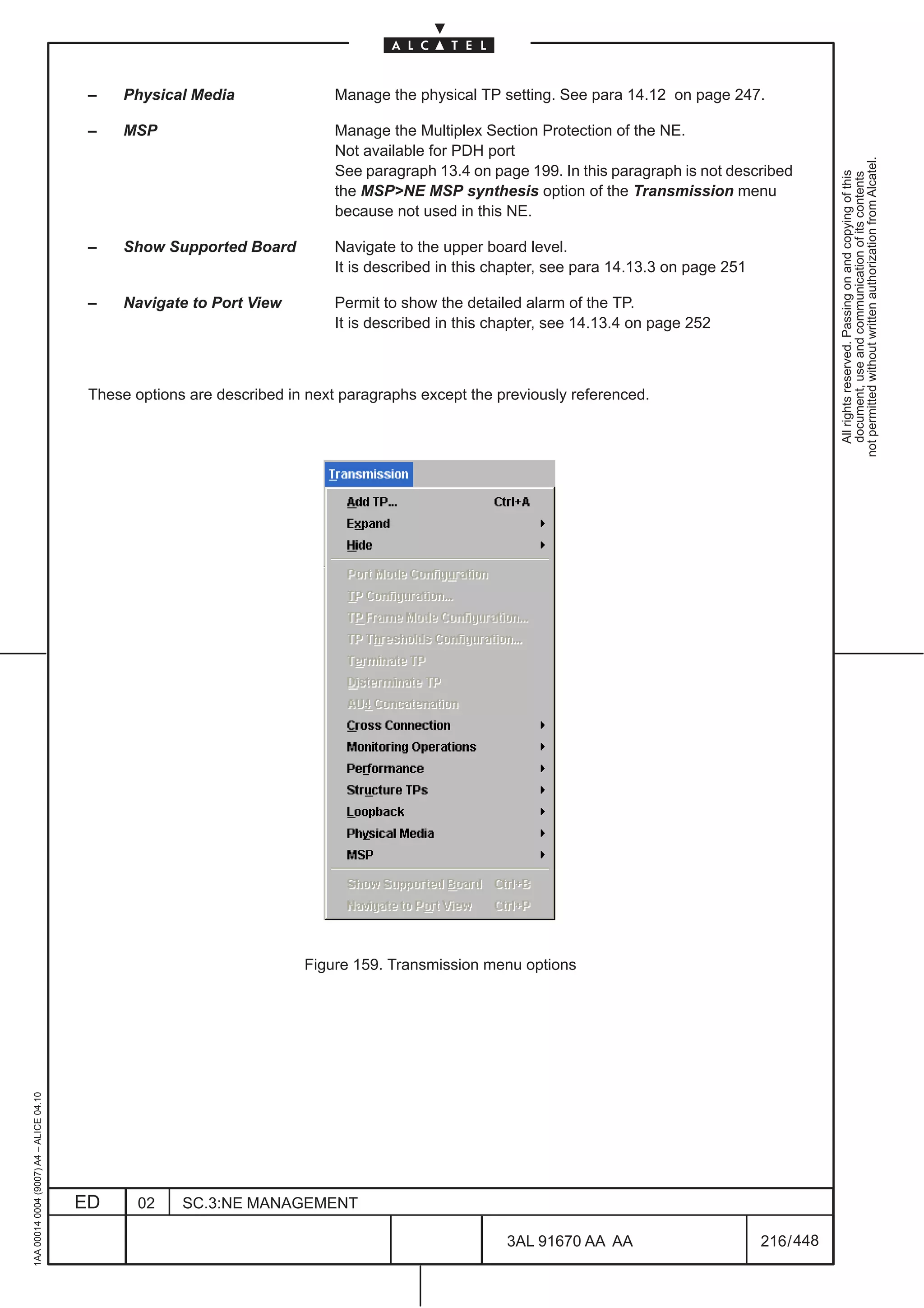
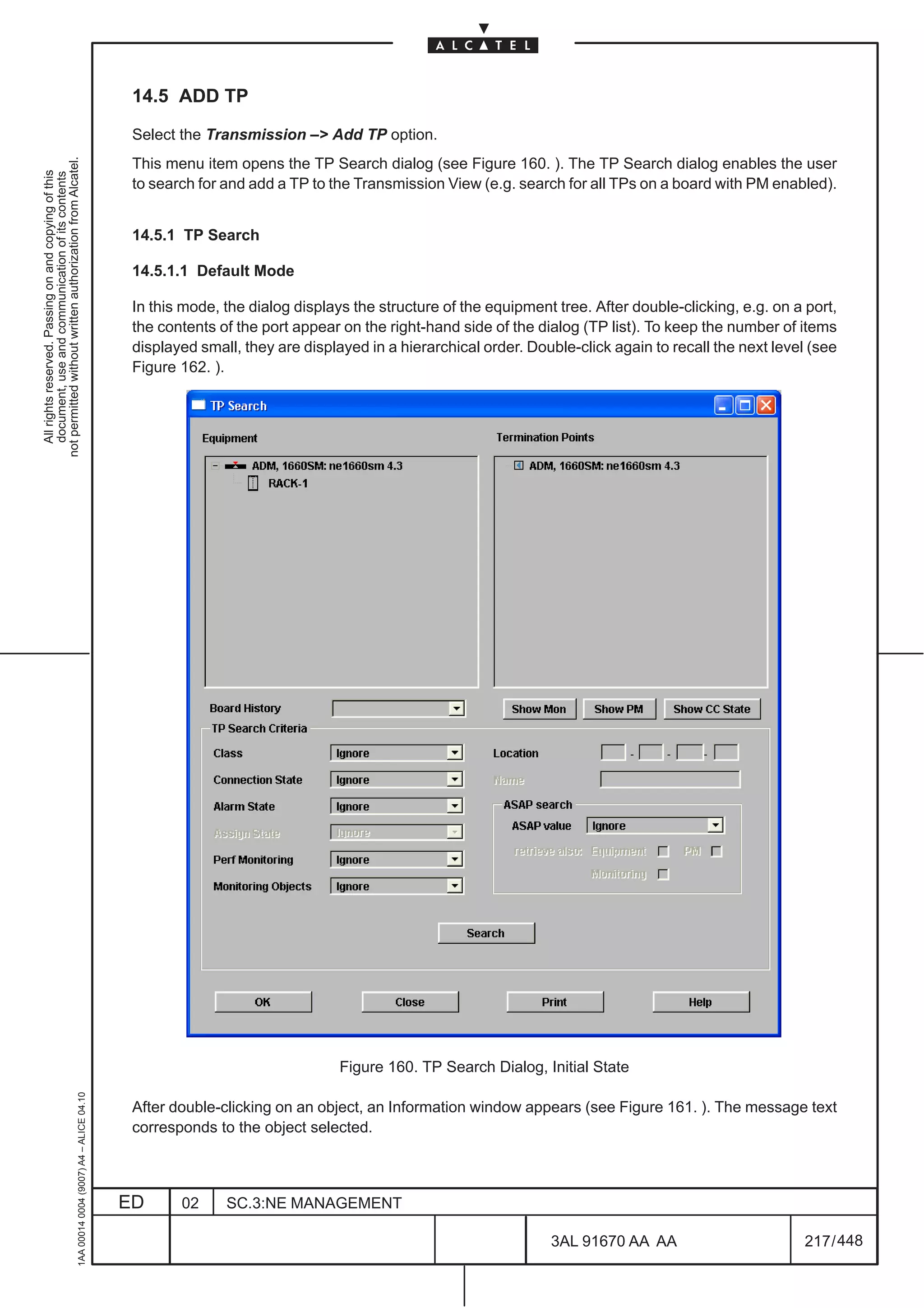
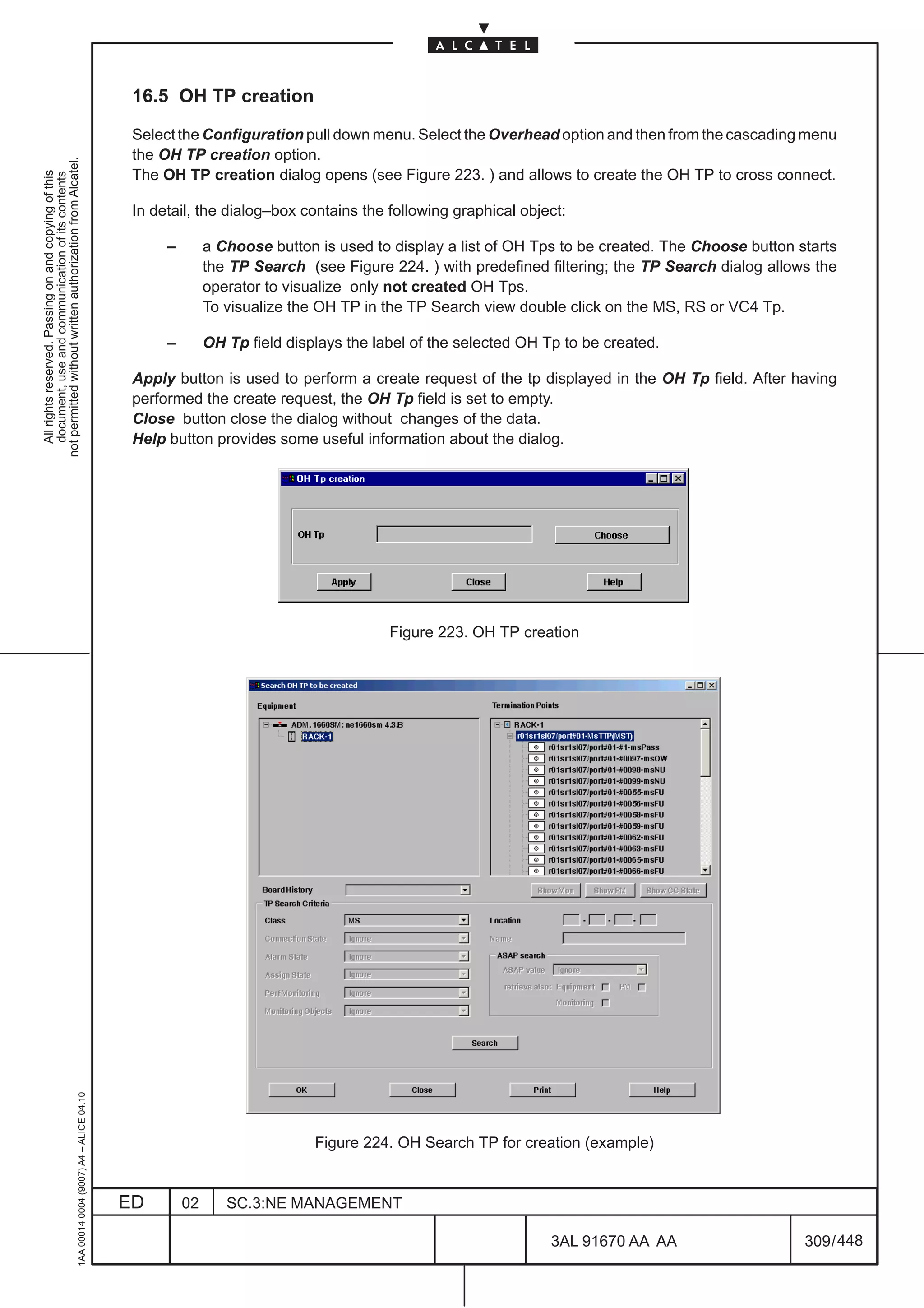
![8.11 IP Static Routing Configuration
Select the Configuration pull down menu. Select the Comm/Routing–>IP Configuration and then from
the cascading menu, the IP Static Routing Configuration option.
not permitted without written authorization from Alcatel.
The dialog–box opens (Figure 63. ) and allows to configure the parameters for IP Static Routing
All rights reserved. Passing on and copying of this
document, use and communication of its contents
Configuration.
The following fields and data are present:
[1] Destination Host IP Address: allows to define the IP address necessary to reach a specific Host
[2] Destination Network: it is alternative to Destination Host IP Address; allows to define the
IP Address and IP Mask to reach a network.
[3] Default Gateway IP Address: allows to define the address of the next hop gateway
[4] CLNP (Connection Less Network Protocol): allows to use a pre–define IP over OSI tunnel towards
a gateway. The information in the field is automatically
assigned after the execution of the option “IP over OSI
Tunneling” (see para. 8.16 page 112).
[5] IP Point–to–Point Interface Id: allows to use point to point interfaces made available by EC
N.B. Points from [3] to [5] are alternative
Apply button is used to perform a configuration change of the data contained in the complete table and
close the view; the view is visible until the end of the operations and a wait cursor is displayed.
New button is used to insert a new page.
Delete button is used to delete the selected page.
Close button close the dialog without changes of the data.
1AA 00014 0004 (9007) A4 – ALICE 04.10
Figure 63. IP Static Routing Configuration (example)
ED 02 SC.3:NE MANAGEMENT
3AL 91670 AA AA 107 / 448
448](https://image.slidesharecdn.com/1660smoperr4-452b-100224044515-phpapp01/75/1660-S-M-Oper-R4-155-2048.jpg)


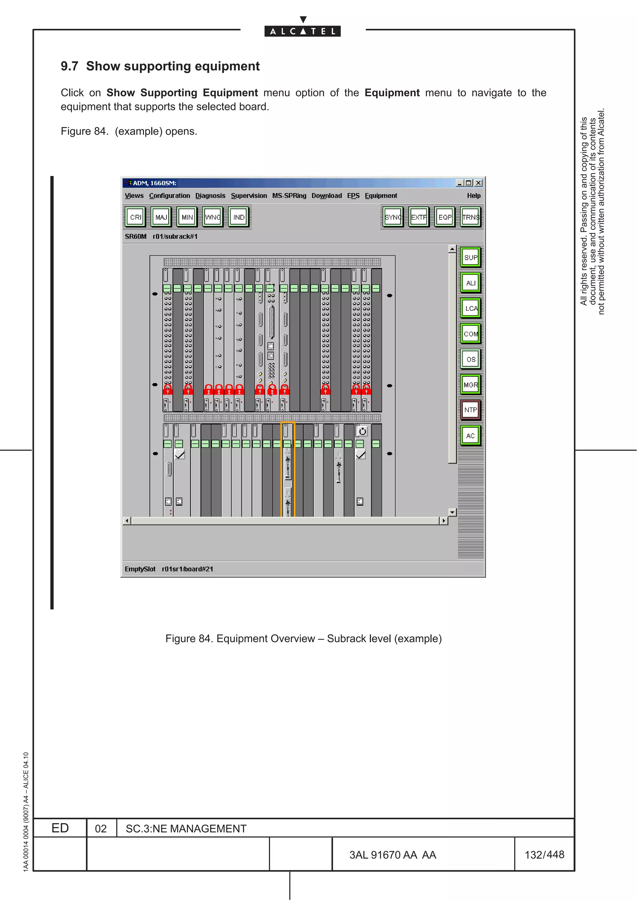
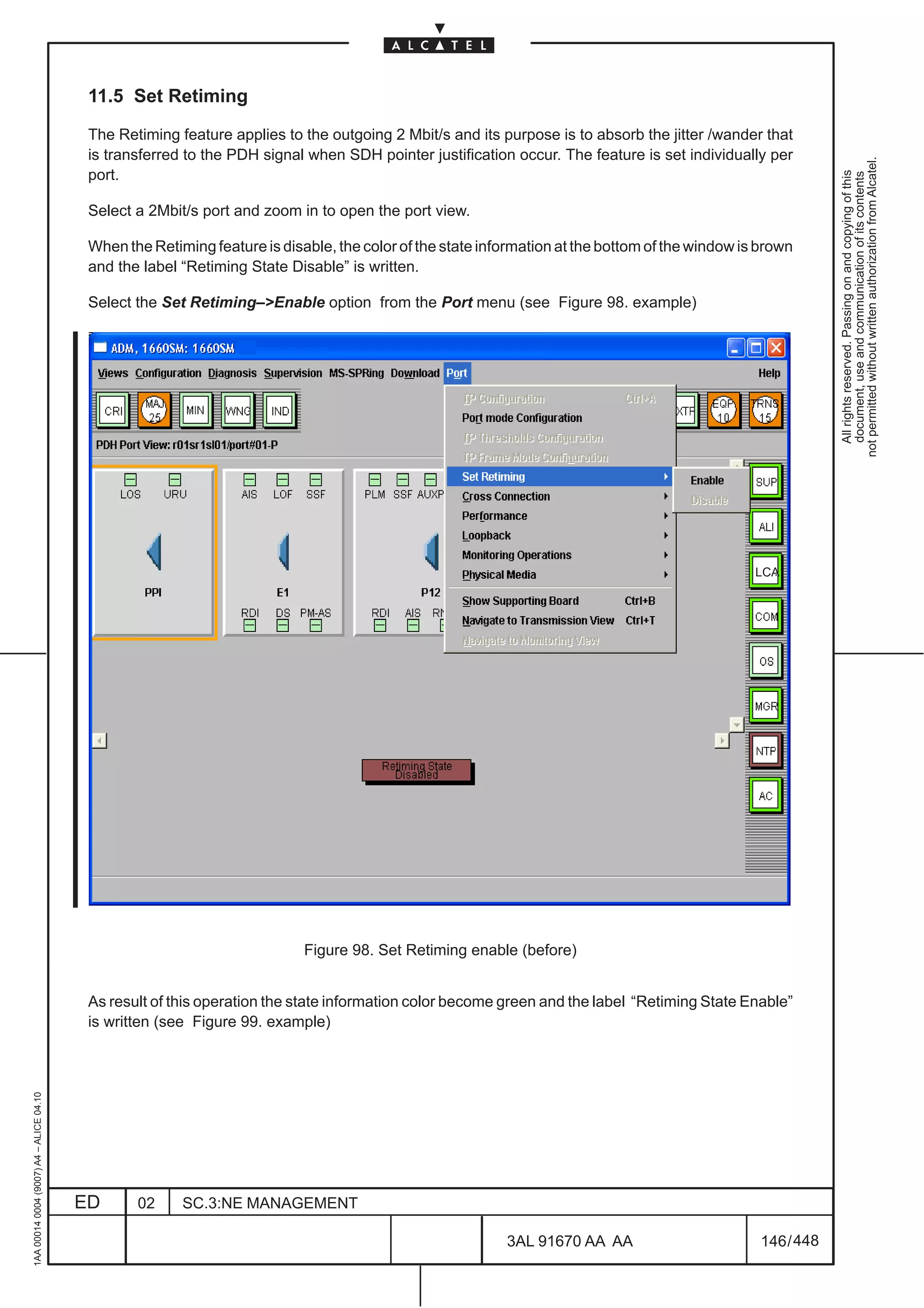
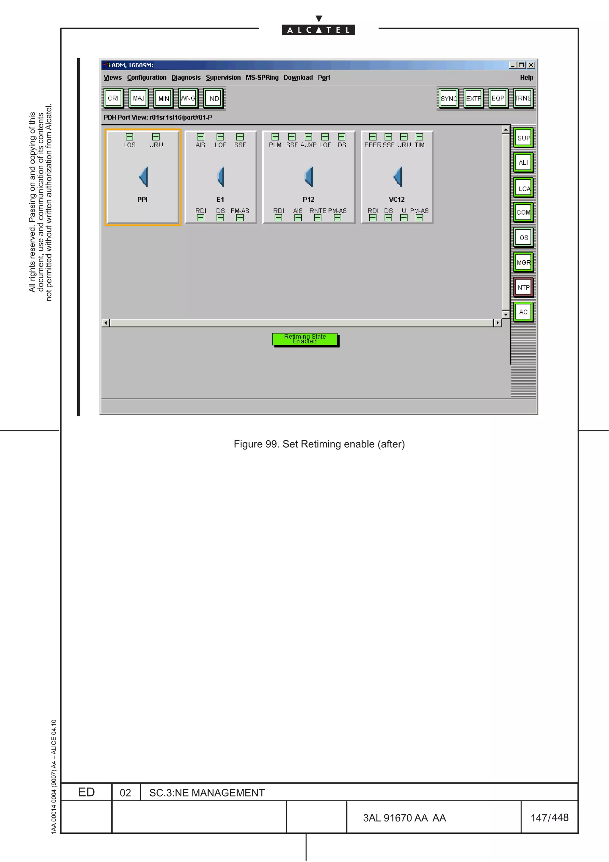
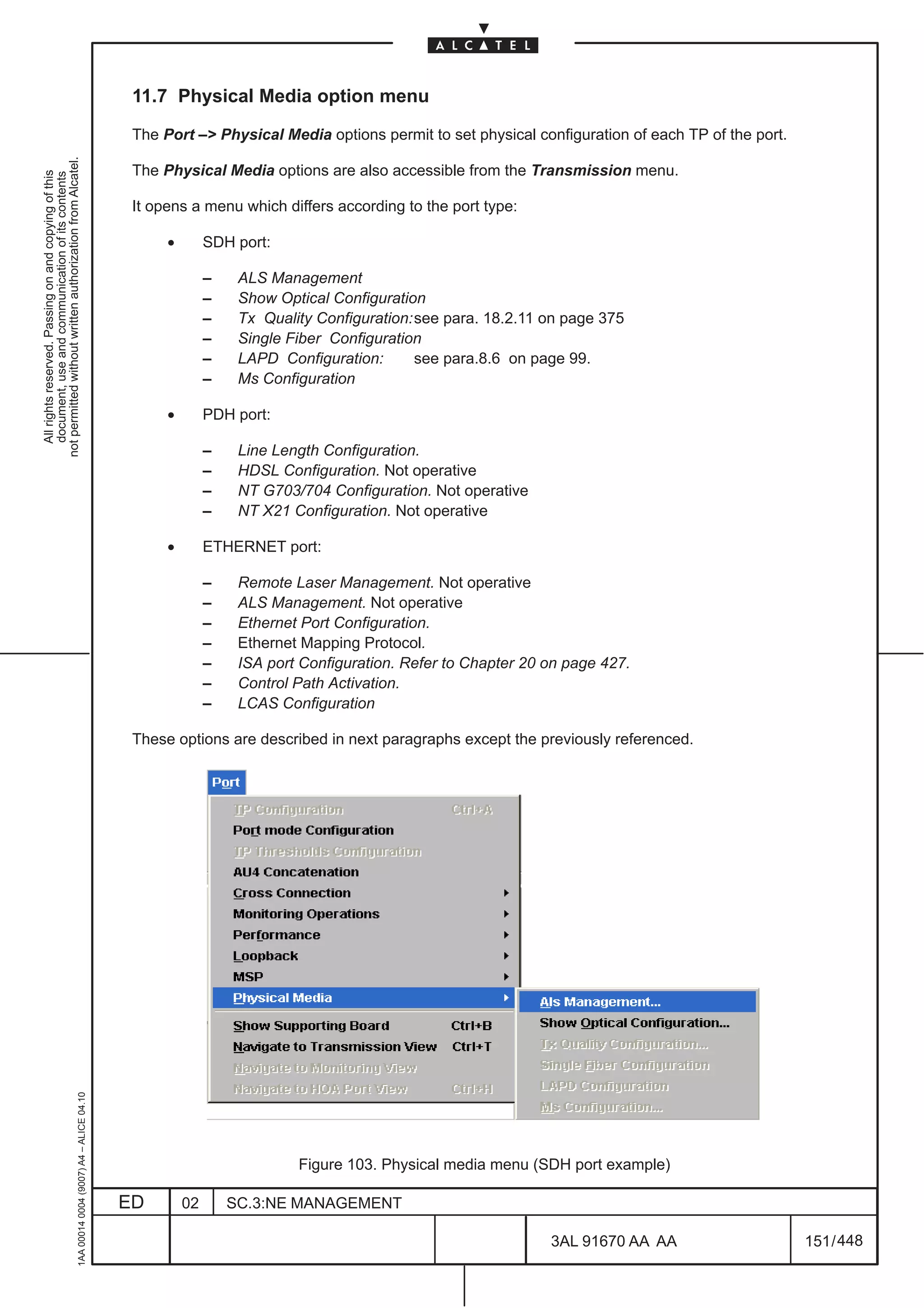
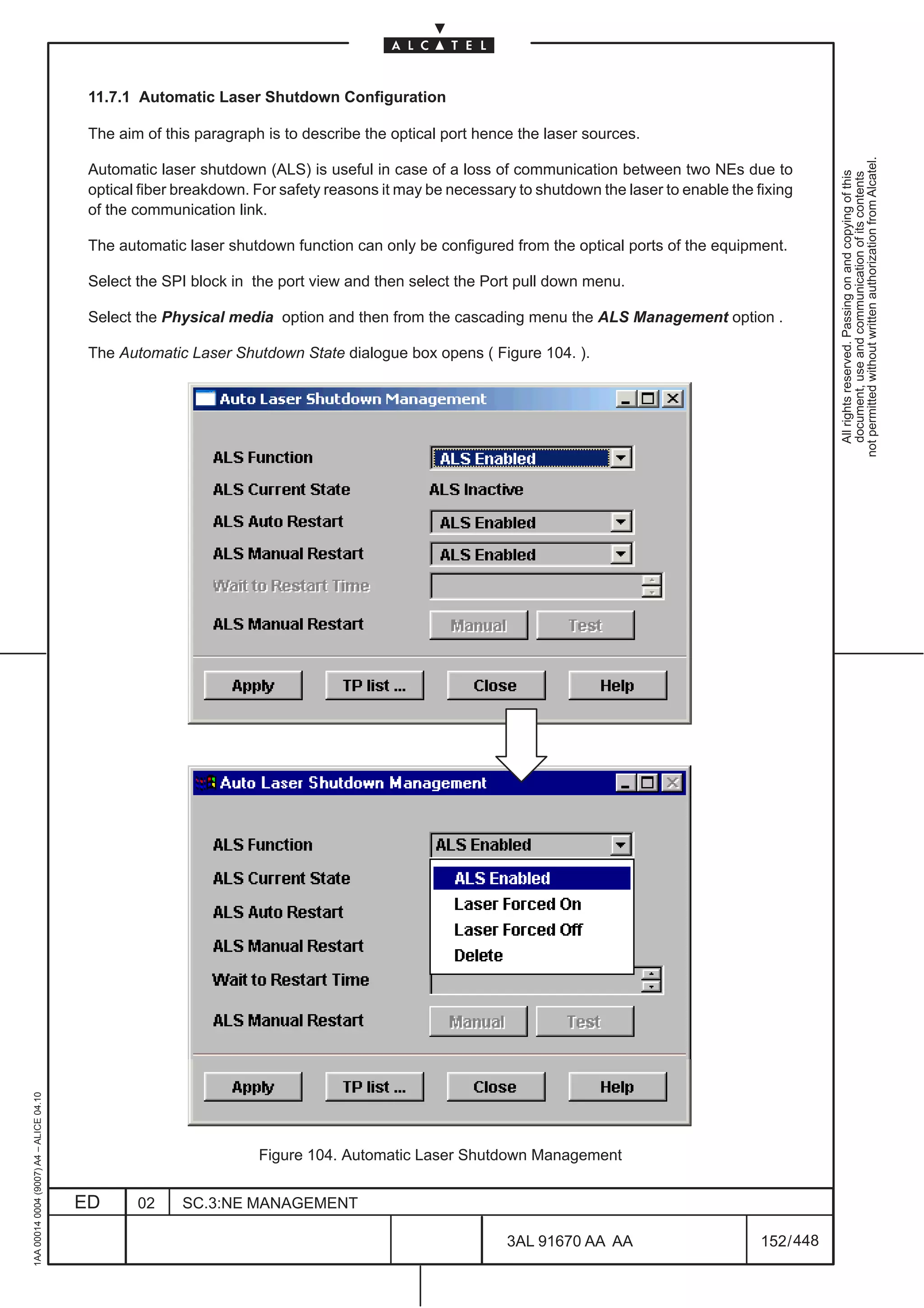
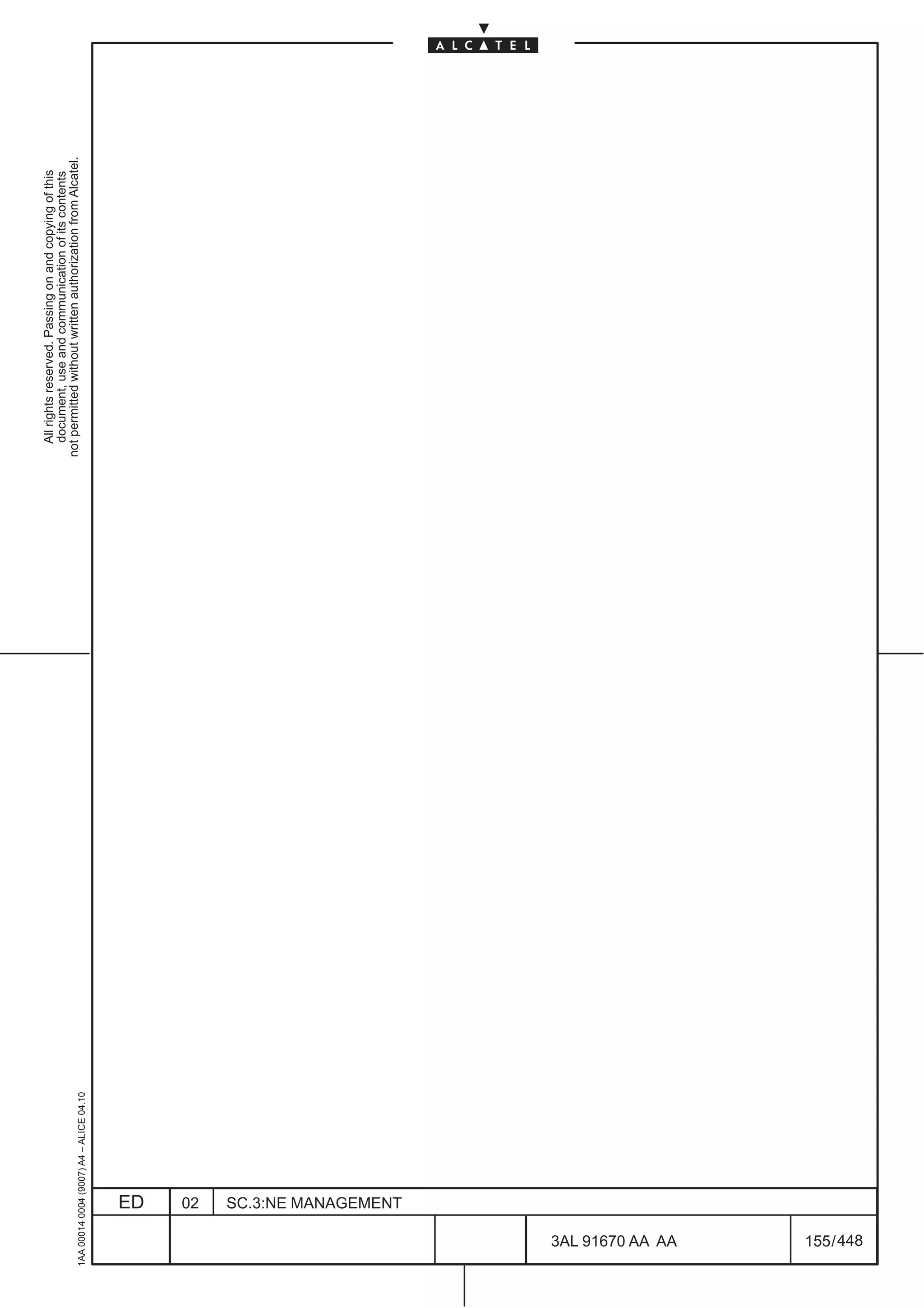
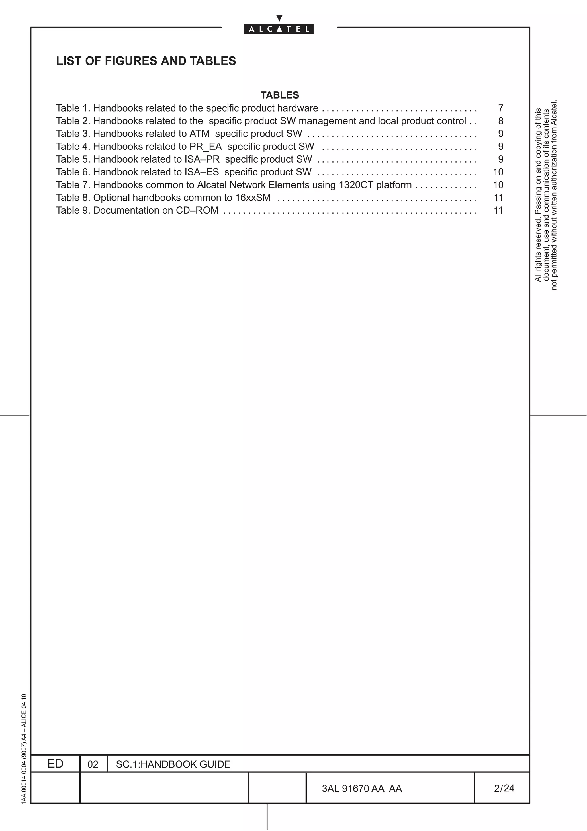
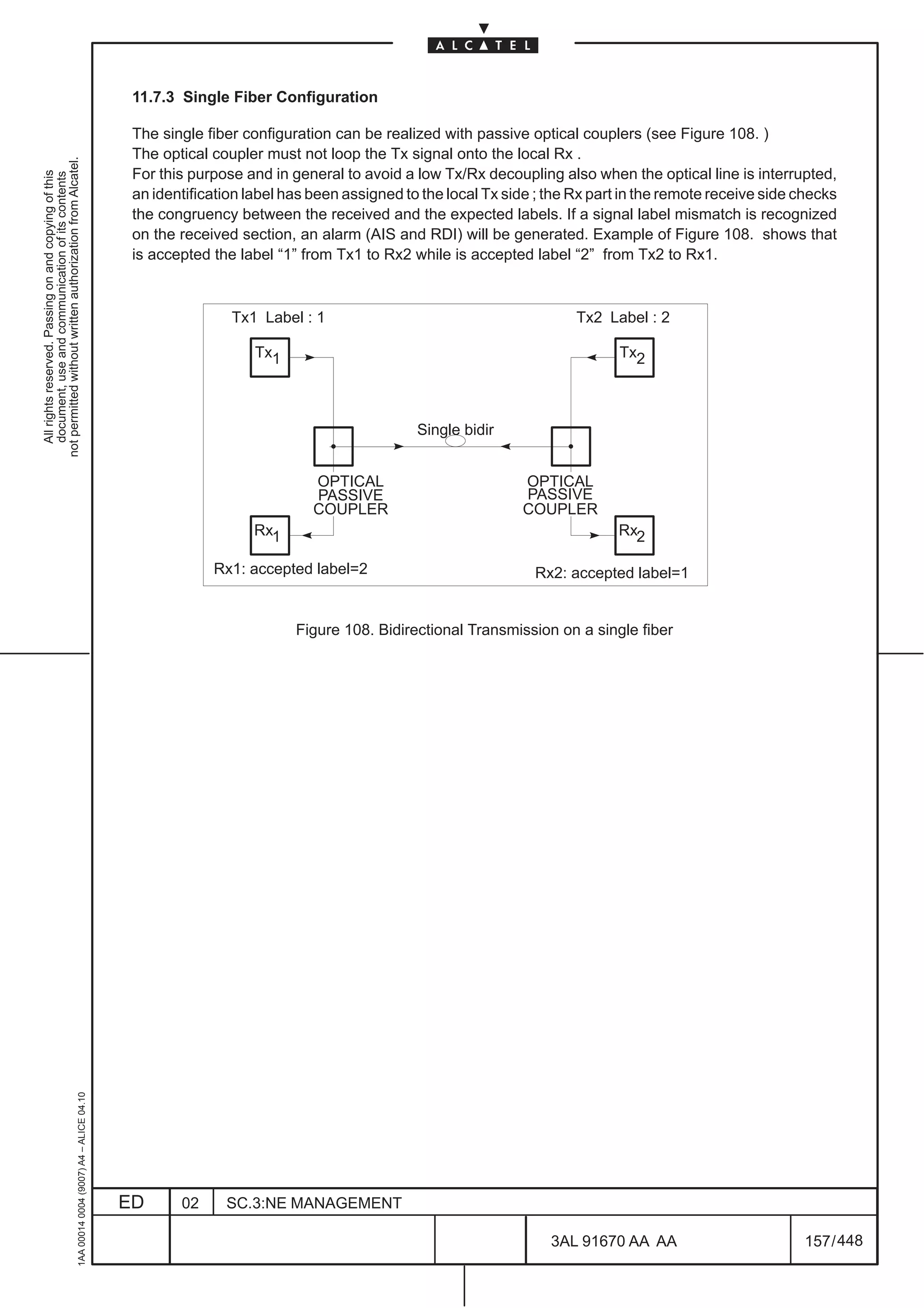
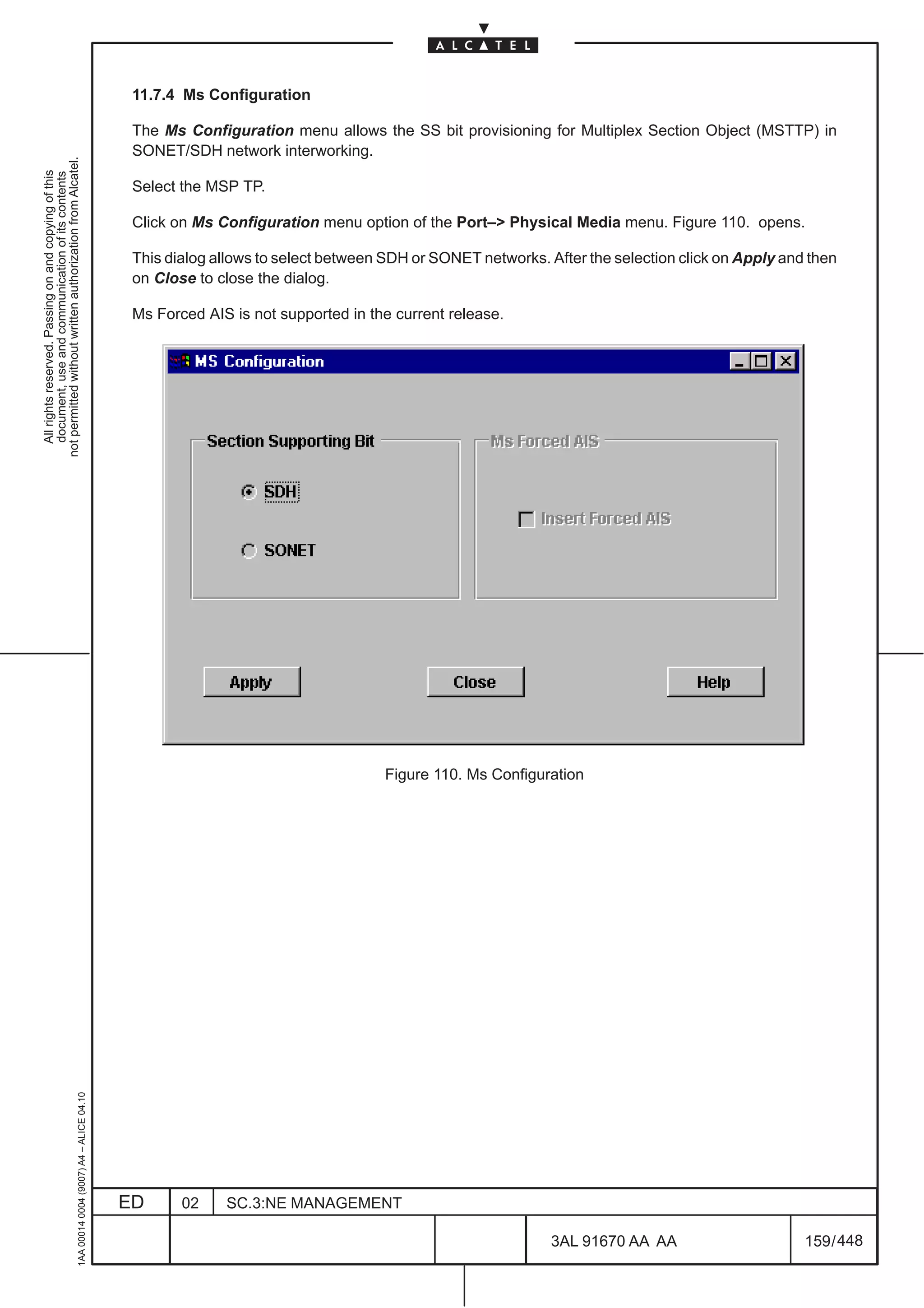
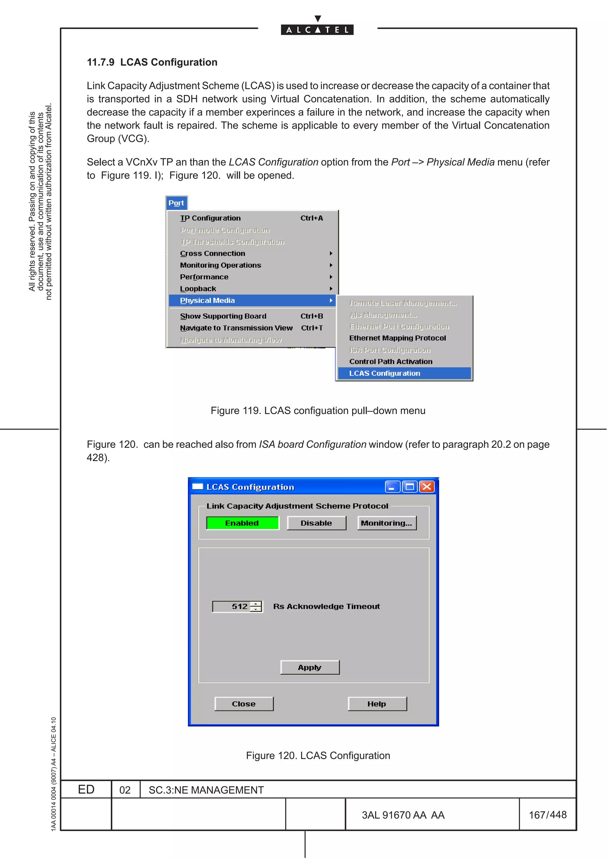
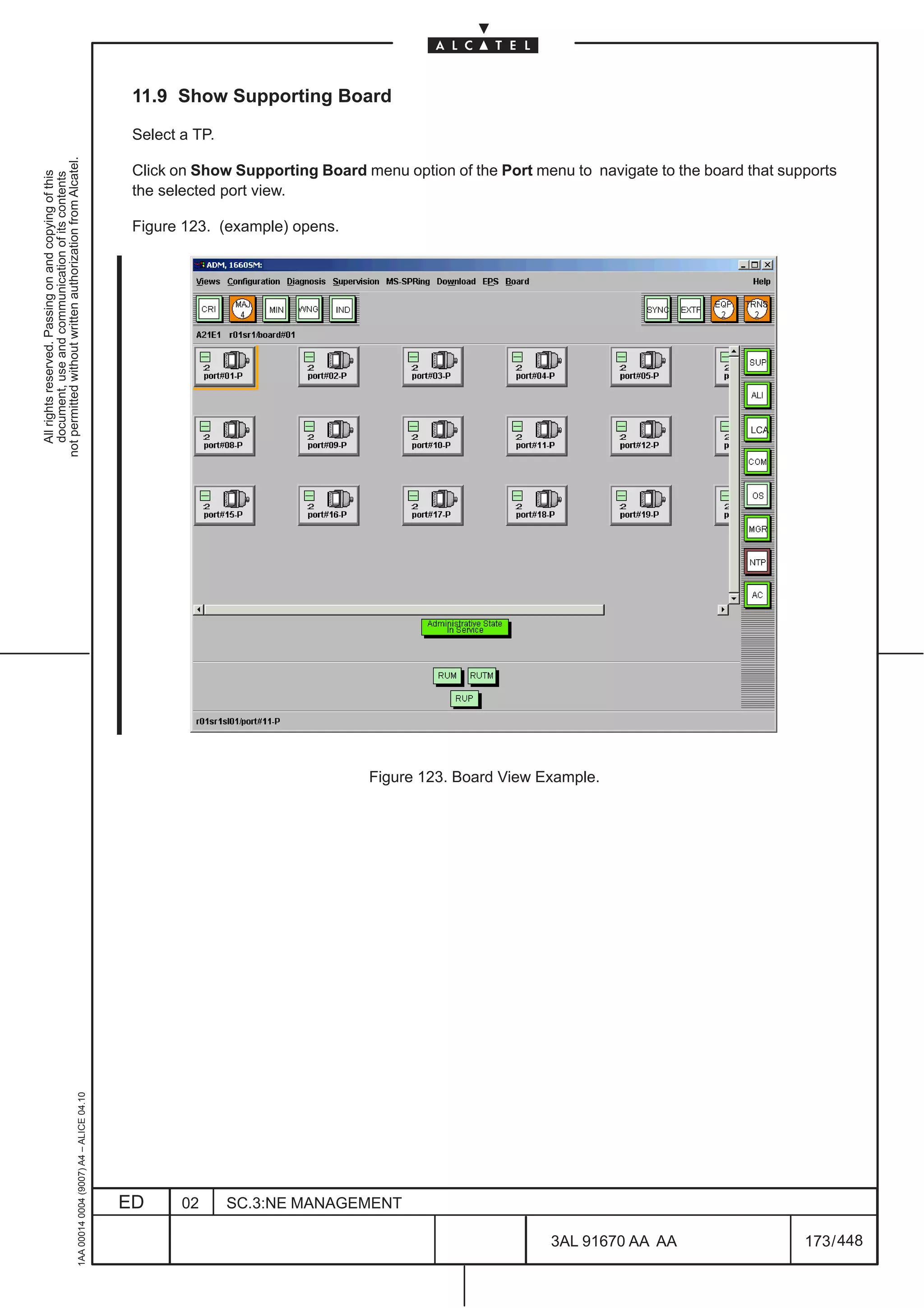
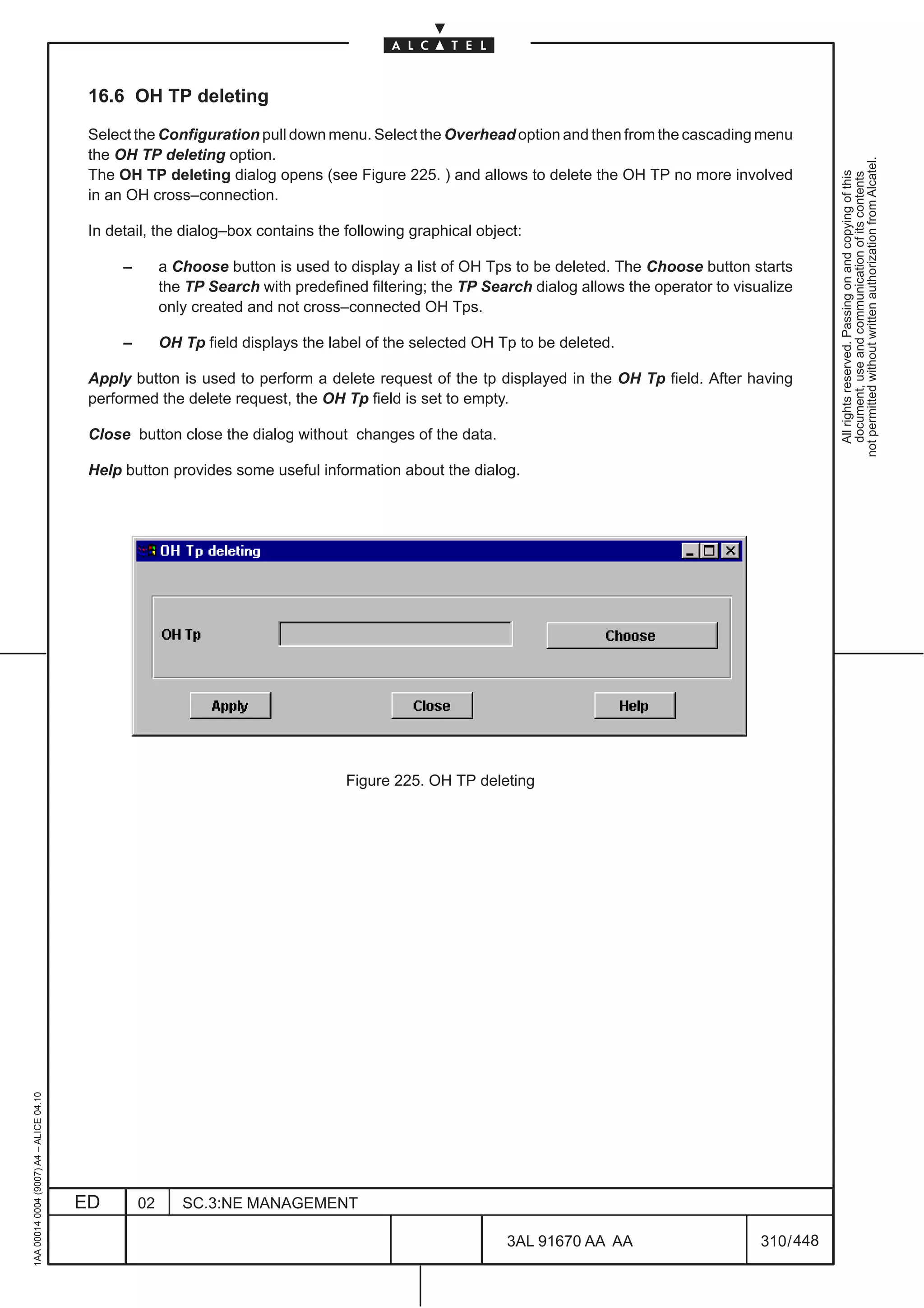
![11.7.2 Show Optical Configuration
This command permits to get detailed information on the optical characteristics of the port that is
visualized.
not permitted without written authorization from Alcatel.
All rights reserved. Passing on and copying of this
document, use and communication of its contents
Firstly select an optical board and the SPI block, then click on Show Optical Configuration option from
the Physical media pull down menu to visualize the parameters of the selected optical port.
Figure 107. shows an example of the parameters of the selected interface.
N.B. This dialogue box can only be read. You cannot write in the entry boxes.
Figure 107. Visualizing a port optical parameters (example)
The laser ports are identified by three major characteristics:
– STM Level: describes the input/output optical interface types:
• STM–1 (1640FOX, 1650SMC, 1660SM)
• STM–4 (1640FOX, 1650SMC, 1660SM)
• STM–16 ( only on1660SM)
• STM–64 ( only on1660SM Rel. 5.1 )
– The wavelength of the laser source: the units are nanometers (nm = 10–9 m).
– The use of the port: describes whether the laser port is used for intraoffice transmissions on long
distances (Long Haul ] 40 km) or for infraoffice transmissions on short distances (Short Haul ]
15 km).
1AA 00014 0004 (9007) A4 – ALICE 04.10
The Colored Interface Parameters display the Channel used and the Grid spacing.
To close the dialogue box click on the Cancel push button.
ED 02 SC.3:NE MANAGEMENT
3AL 91670 AA AA 156 / 448
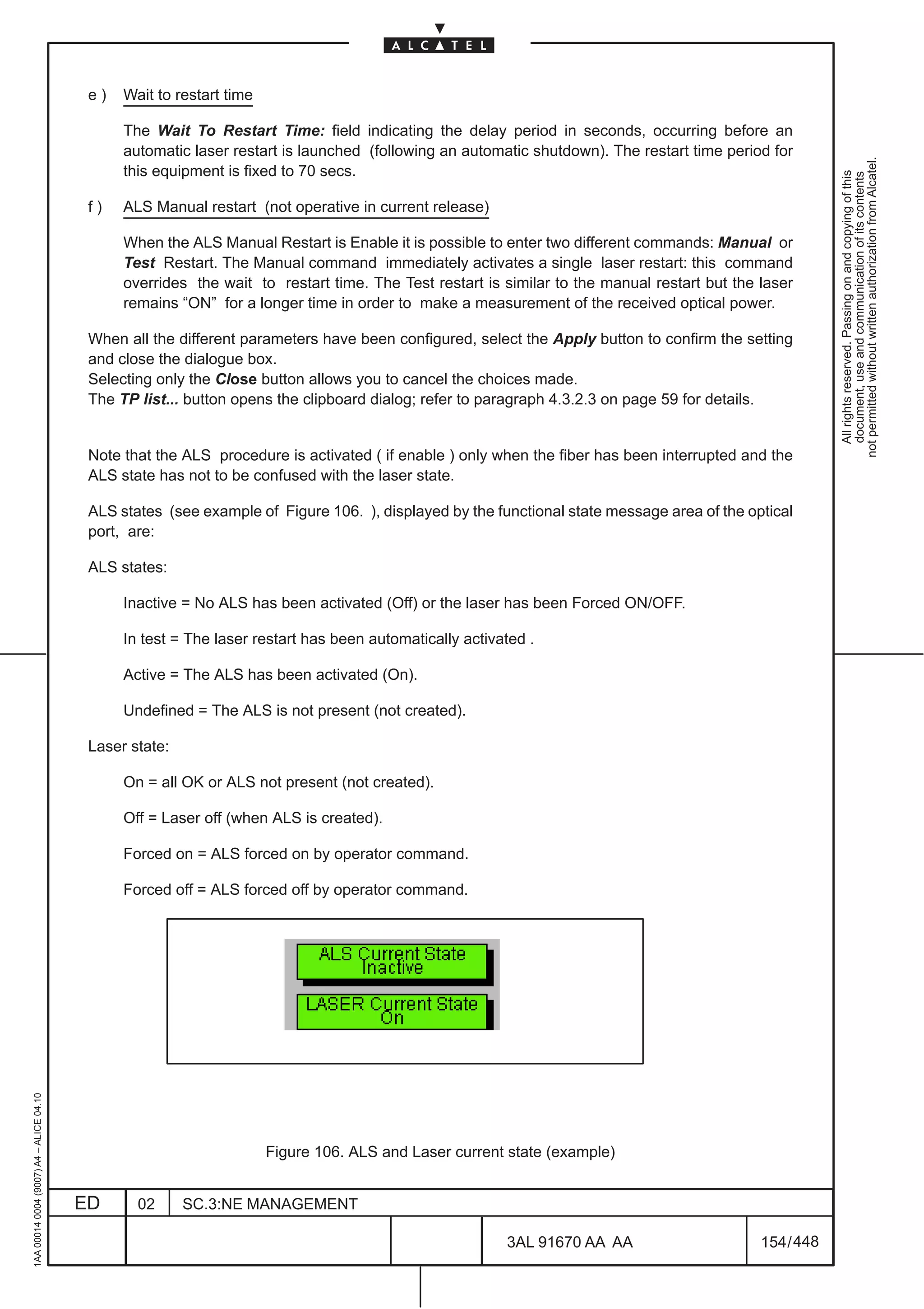
448](https://image.slidesharecdn.com/1660smoperr4-452b-100224044515-phpapp01/75/1660-S-M-Oper-R4-204-2048.jpg)
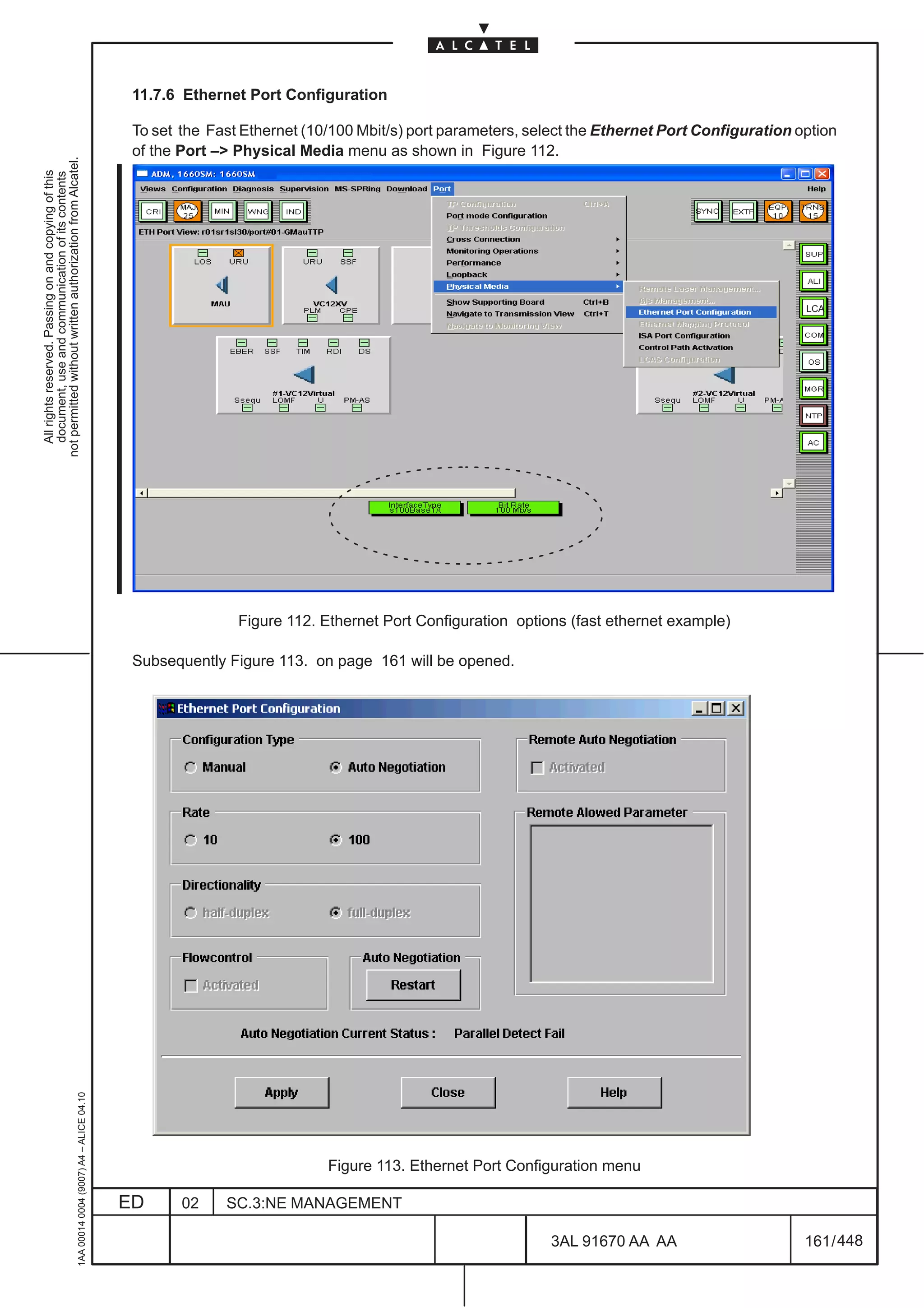
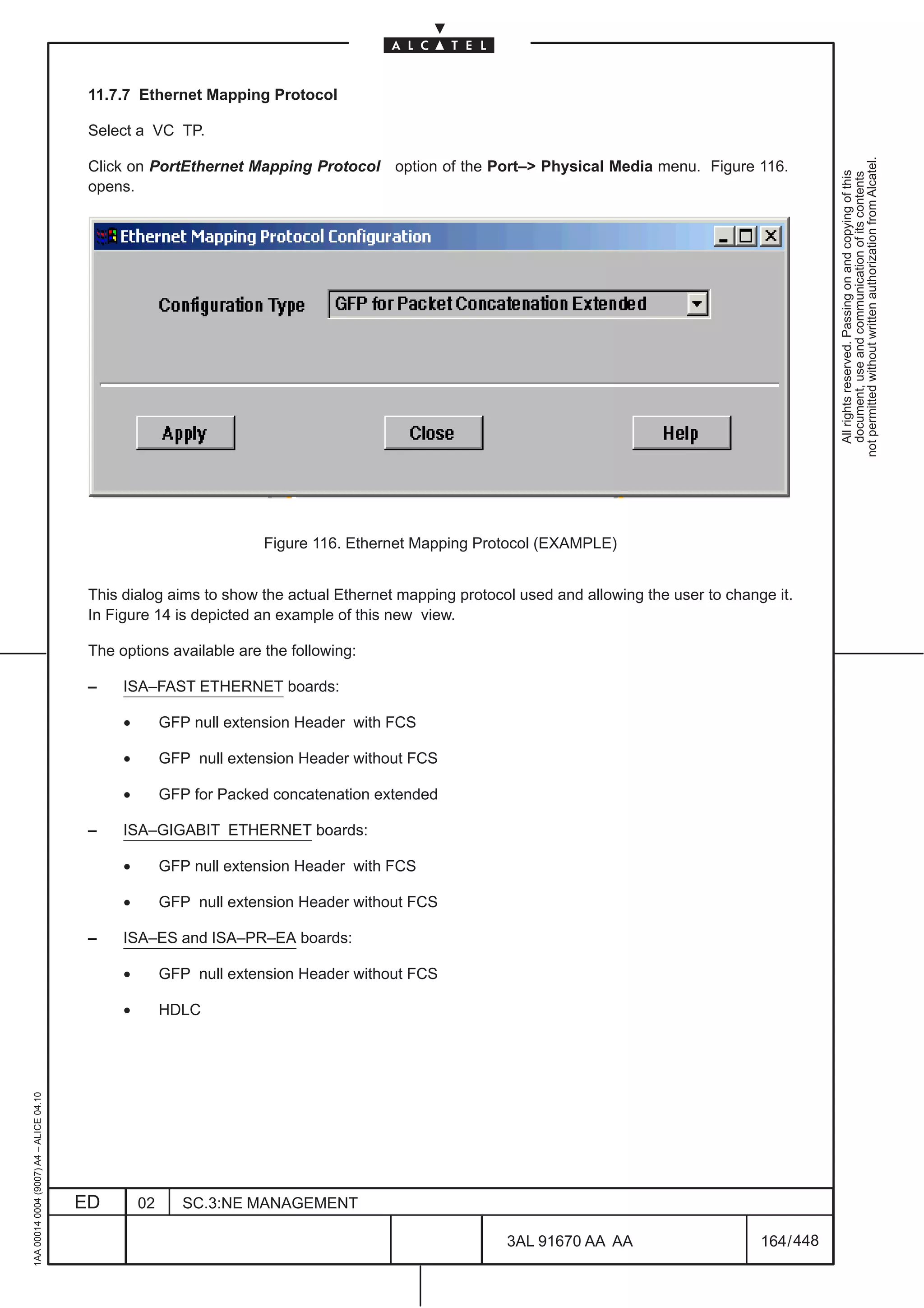
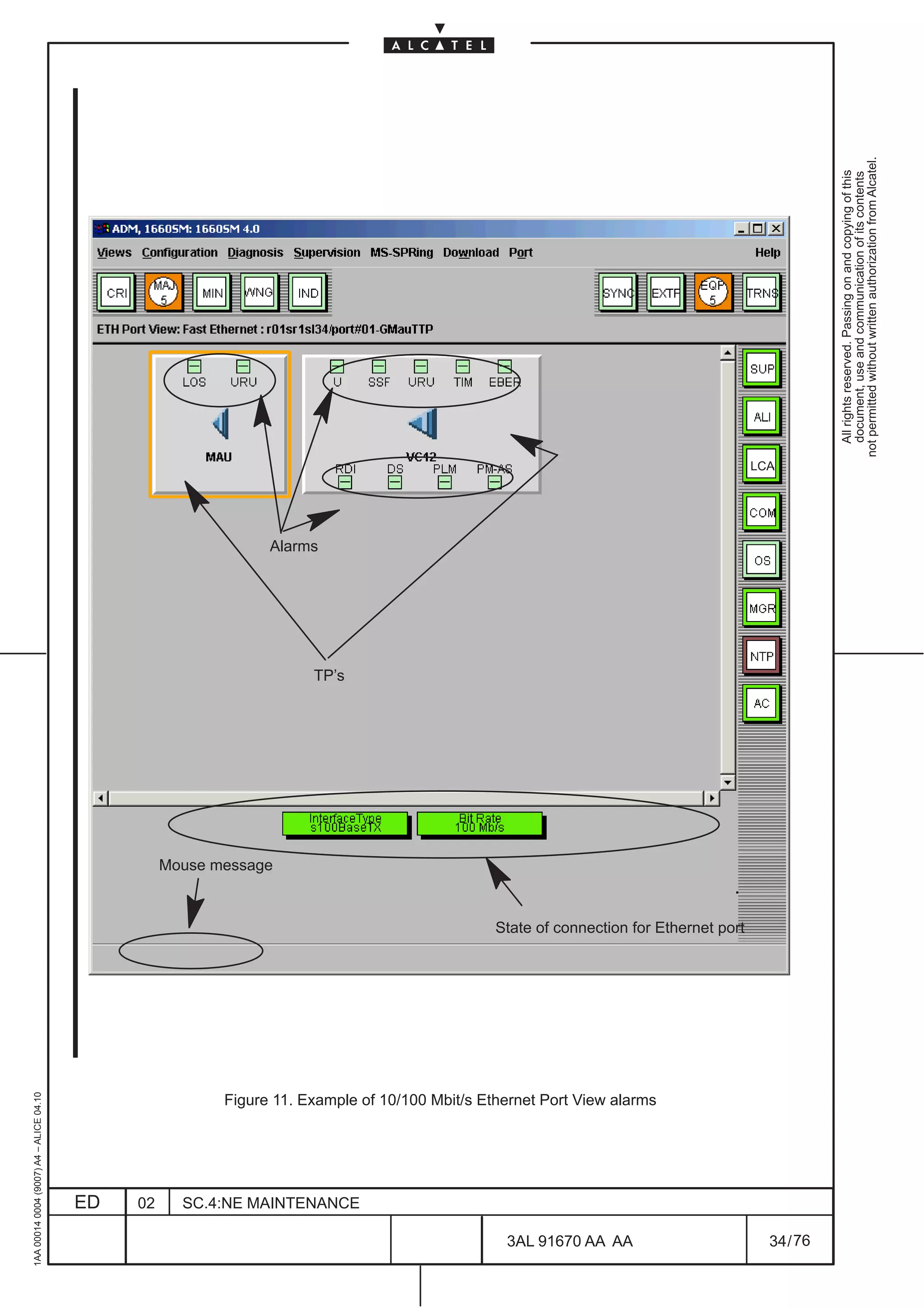
![For the Fast Ethernet (10/100 Mbit/s) port it is possible to choose between two “Configuration Type”:
[1] “Auto Negotiation” : allows to configure the “Rate” to be negotiated (10 or 100 Mb/s).
The “Directionality” (Full Duplex) and the “Flow Control” (Activated) are always enable and can’t
not permitted without written authorization from Alcatel.
be changed.
All rights reserved. Passing on and copying of this
document, use and communication of its contents
[2] “Manual”: allows to force the “Rate “ at 10 or 100 Mb/s .
The “Directionality” is always Full Duplex.
Moreover It is possible to Restart the “Auto Negotiation” by depressing the relevant button; if parameters
has been changed before pressing the Restart button , a question dialog is displayed (see Figure 114.
on page 162) to advice that the user has changed data but not applied them.
Figure 114. Information dialog
In read only mode there are indication if the Auto negotiation on remote side is activated (Remote Auto
Negotiation) and what parameters are allowed on remote (Remote Allowed Parameters).
In both cases is possible to check the the “Auto negotiation Current State” with the possible massage:
– completed OK
– completed KO
– configuring
– deactivated
– parallel Defect Fail
– other
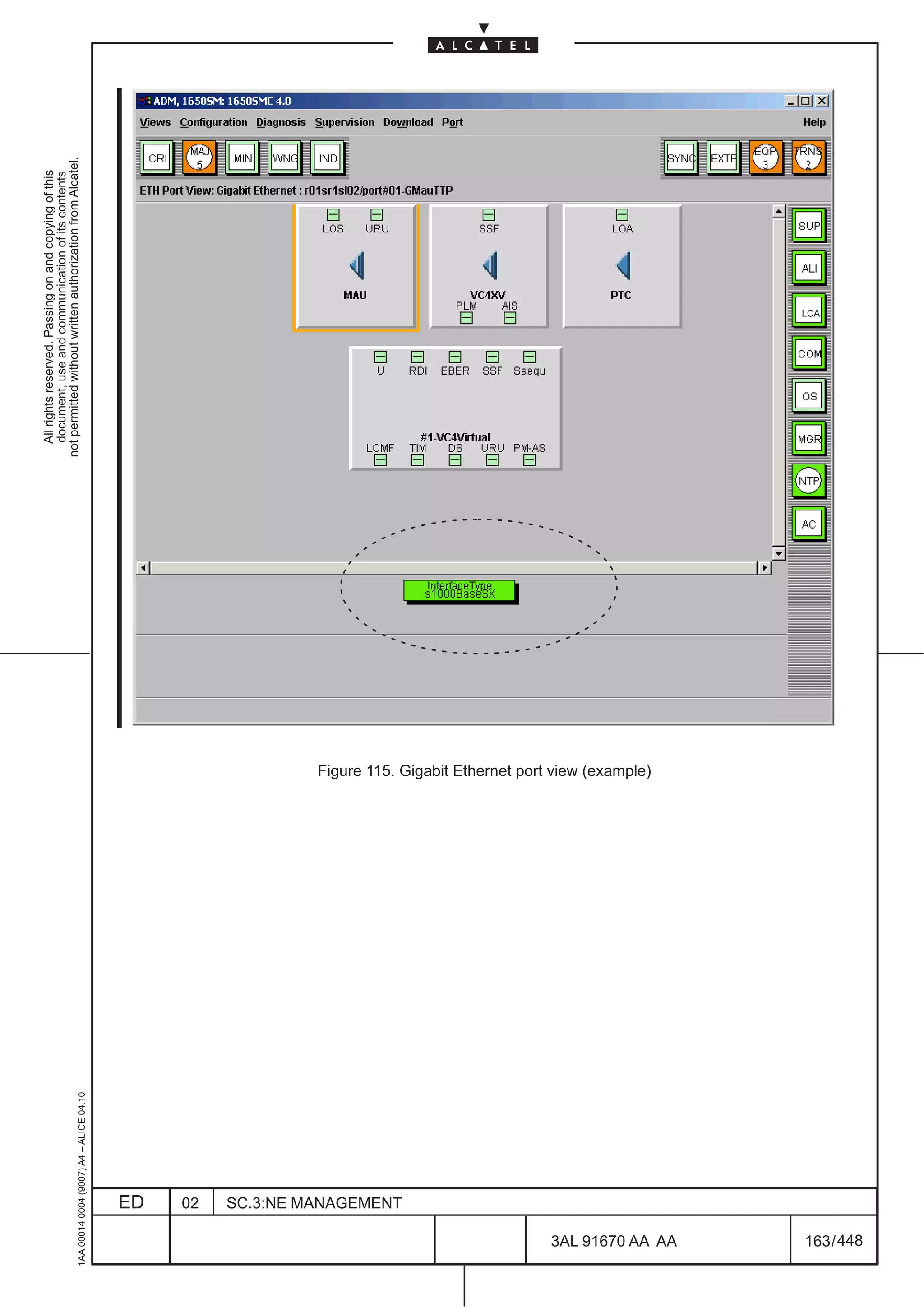
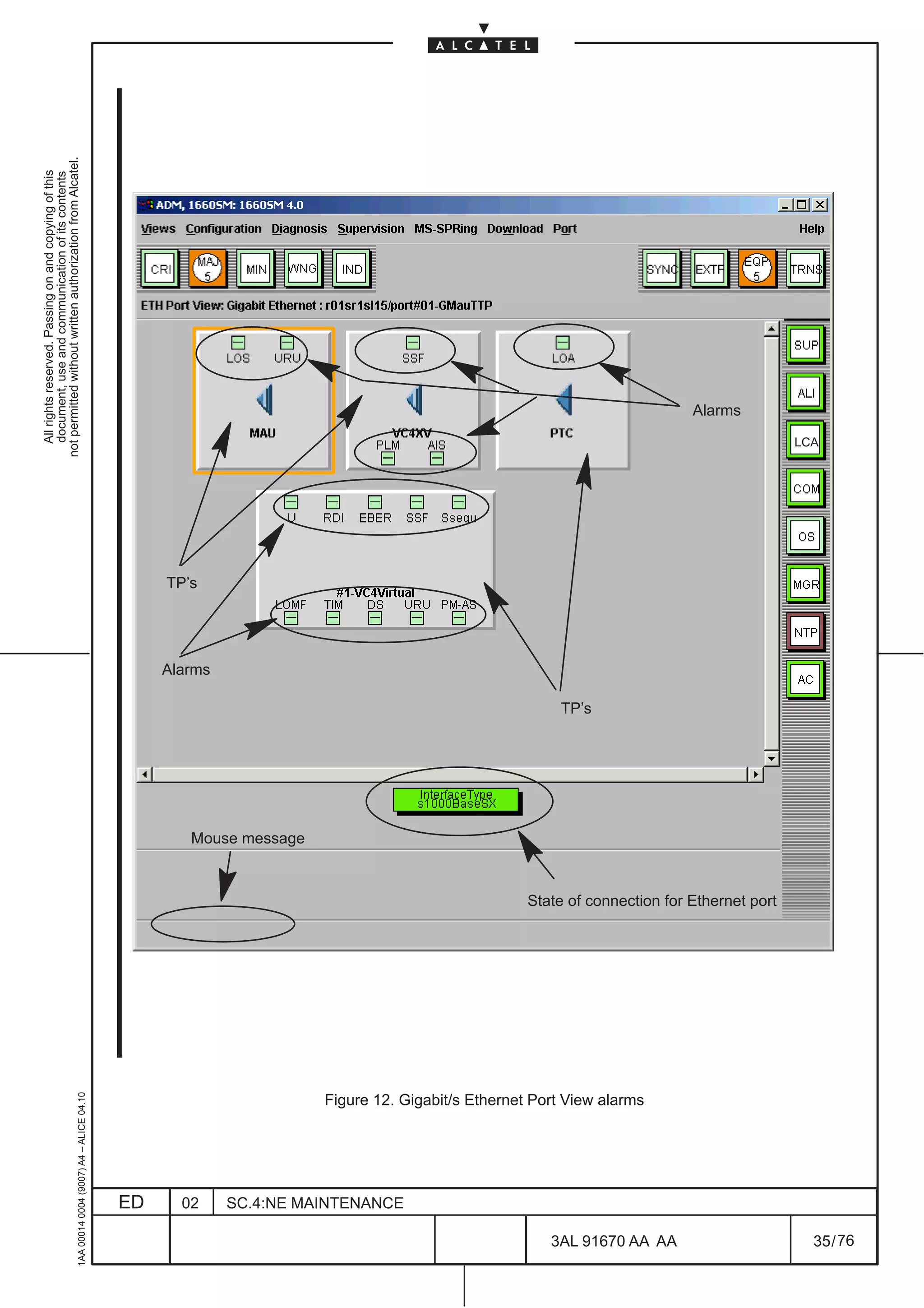
At the bottom of the port view are displayed the following indications (refer to Figure 112. on page 161
and Figure 115. on page 163):
– the “Interface Type”:
• S1000 Base SX (only for Gigabit Ethernet board)
• S1000 Base LX (only for Gigabit Ethernet board)
• S1000CX (only for Gigabit Ethernet board)
• S100BaseTX
• S100BaseFX
• Unknown
• S10BaseT
– the “Bit Rate” (only for fast ethernet board):
• 10 Mb/s
• 100 Mb/s
1AA 00014 0004 (9007) A4 – ALICE 04.10
ED 02 SC.3:NE MANAGEMENT
3AL 91670 AA AA 162 / 448
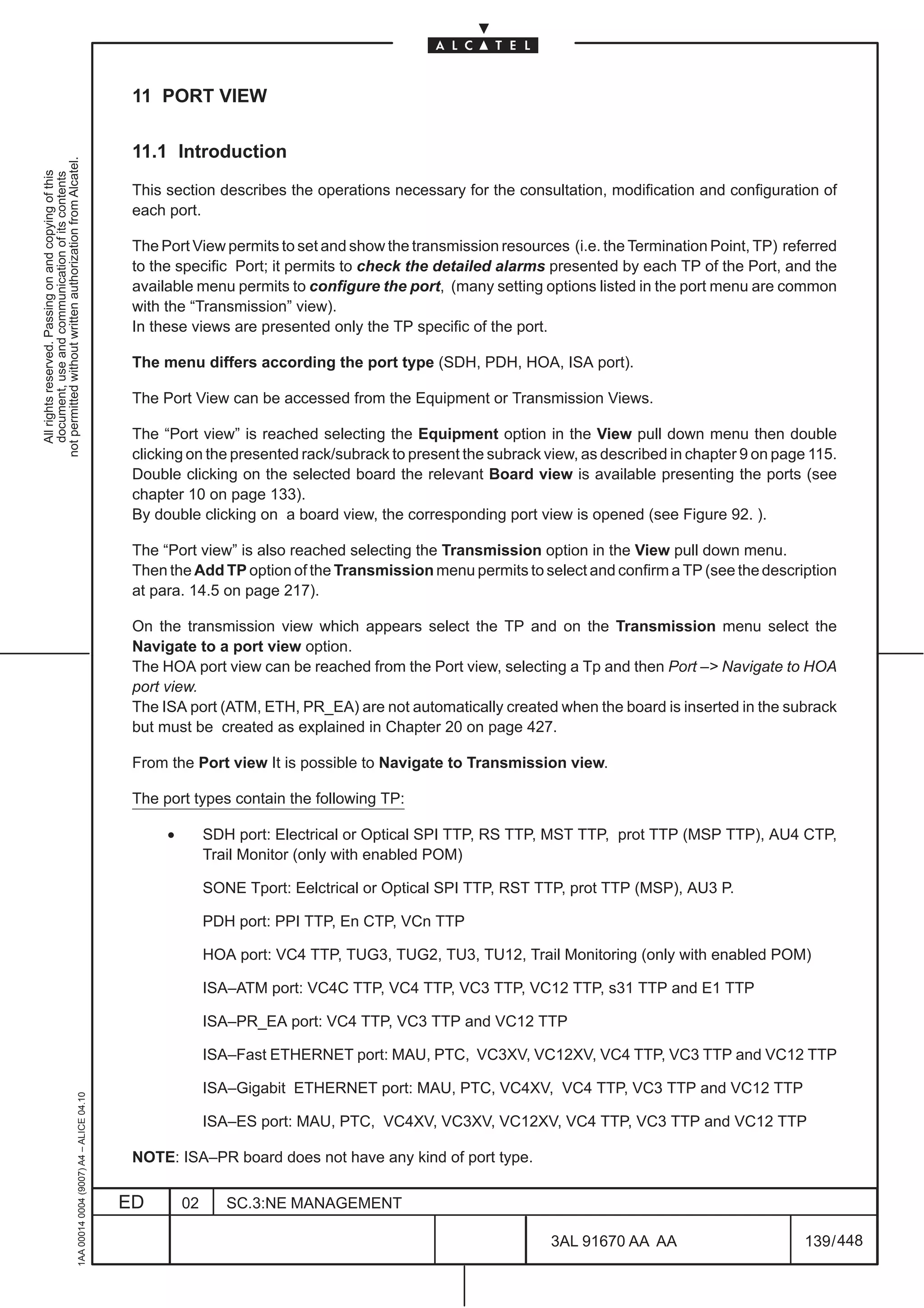
448](https://image.slidesharecdn.com/1660smoperr4-452b-100224044515-phpapp01/75/1660-S-M-Oper-R4-210-2048.jpg)
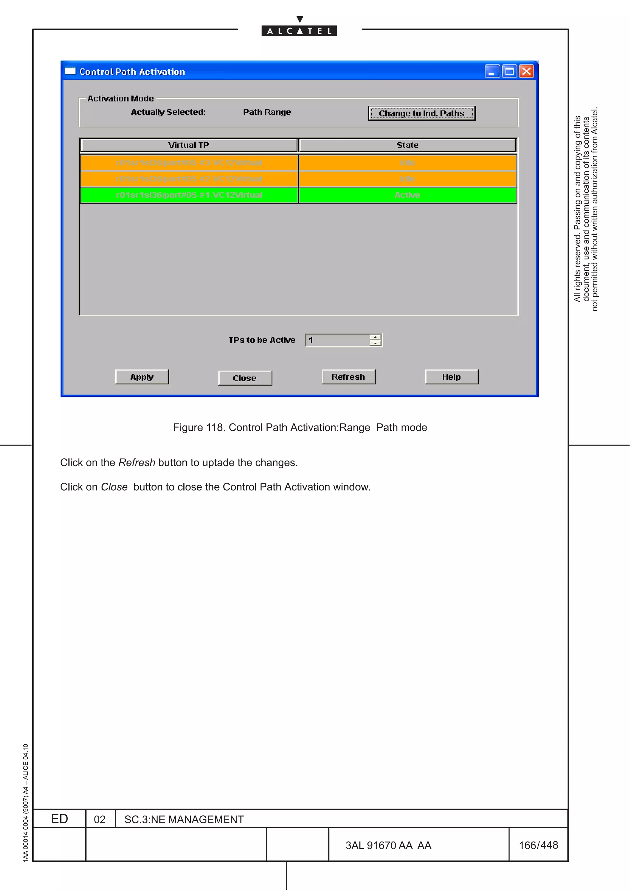
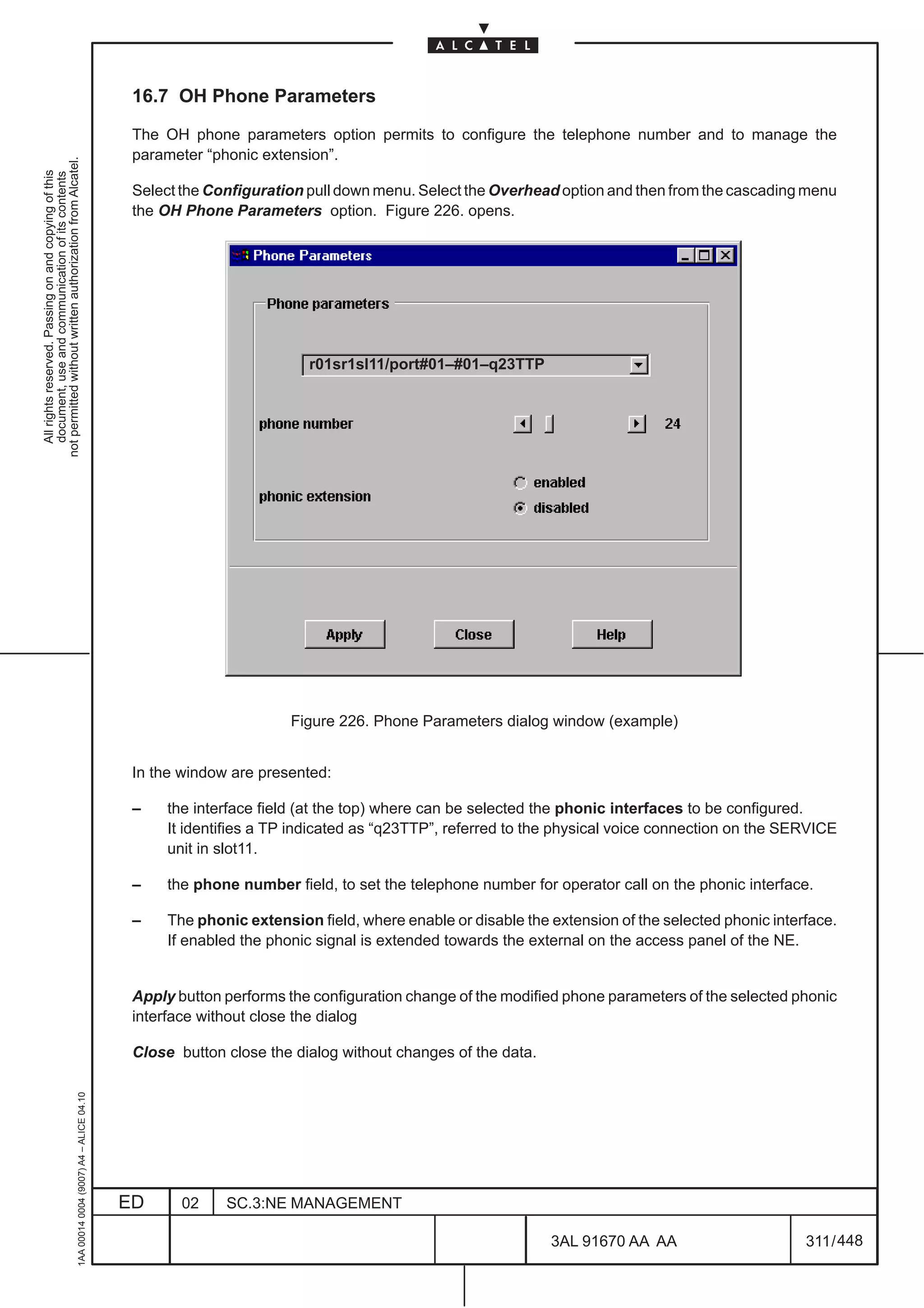
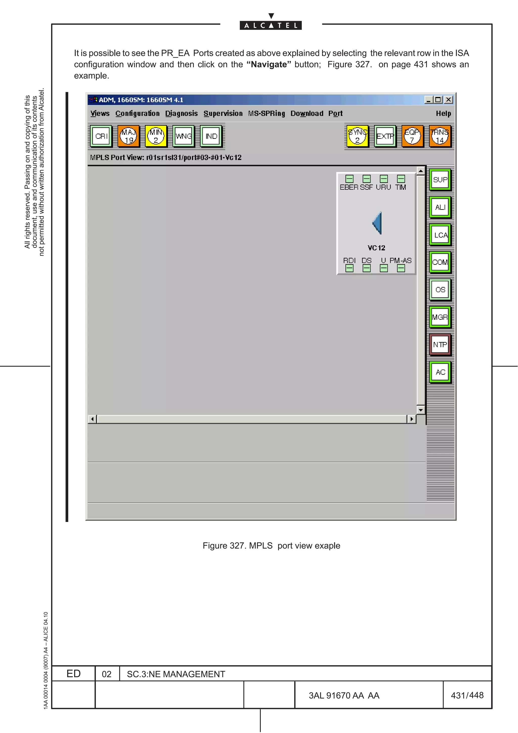
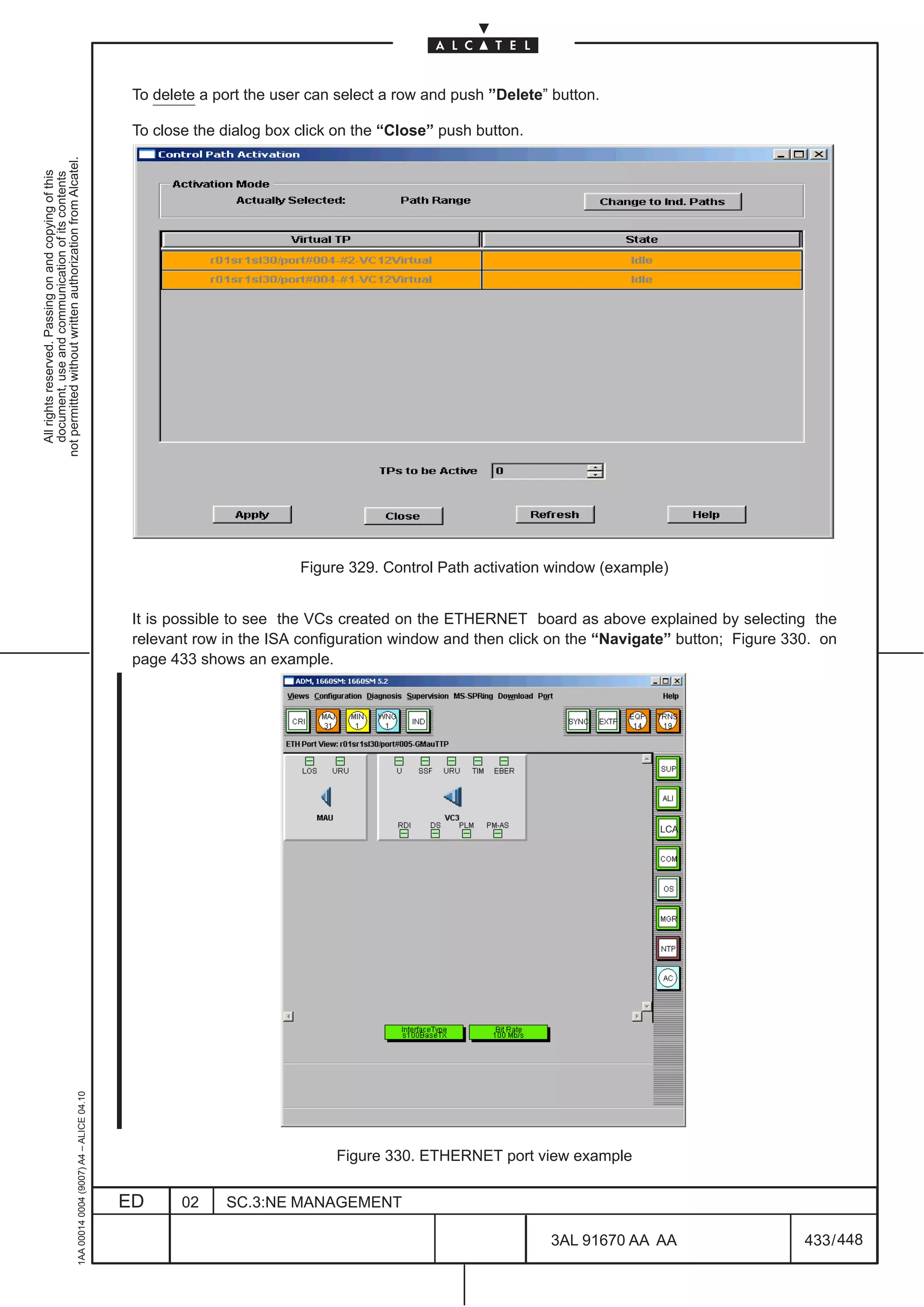
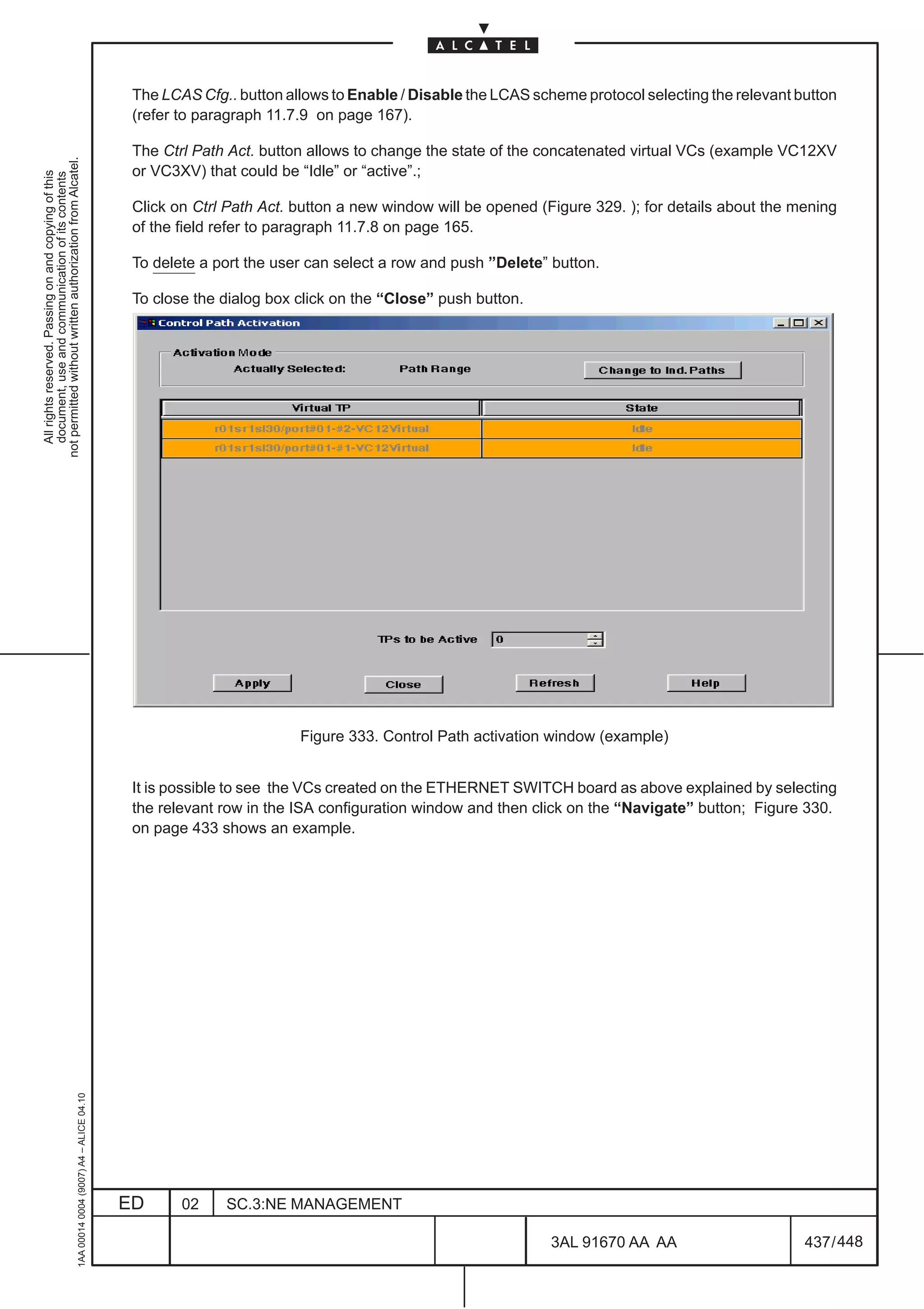
![11.7.8 Control Path Activation
This dialog allows to modify the state of the Ethernet port virtualTPs, created as explained in Chapter
20 on page 427.
not permitted without written authorization from Alcatel.
All rights reserved. Passing on and copying of this
document, use and communication of its contents
Select a TP in the Ethernet port view window.
Click on Control Path Activation option of the Port–> Physical Media menu.
A new window will be opened (Figure 117. and Figure 118. are examples); a similar window is display
when a new concatenated VCX is created in the “ISA port configuration” window (refer to paragraph 20.2.3
on page 432).
This dialog aims to show the activation state of the virtualTPs present in the Ethernet Port View and to
change the number of virtual TPs active.
Two modality are foreseen to activateTPs:
[1] Individual path (refer to Figure 117. ): the Active state is reached by selecting the individual row with
the mouse and click on the Change Status button.
[2] Path Range (refer to Figure 118. ):the Active state is reached by choosing the number of “TPs to be
active” and click on the Apply button.
On the contrary to change in Idle the Active state of a TP decrease the “TPs to be active” field and
then and click on the Apply button.
To switch bwtween the two modality click on the relevant button in the Activation Mode field. In this field
it is also displayed the Actual Selected Mode.
1AA 00014 0004 (9007) A4 – ALICE 04.10
Figure 117. Control Path Activation:Individual Path mode
ED 02 SC.3:NE MANAGEMENT
3AL 91670 AA AA 165 / 448
448](https://image.slidesharecdn.com/1660smoperr4-452b-100224044515-phpapp01/75/1660-S-M-Oper-R4-213-2048.jpg)

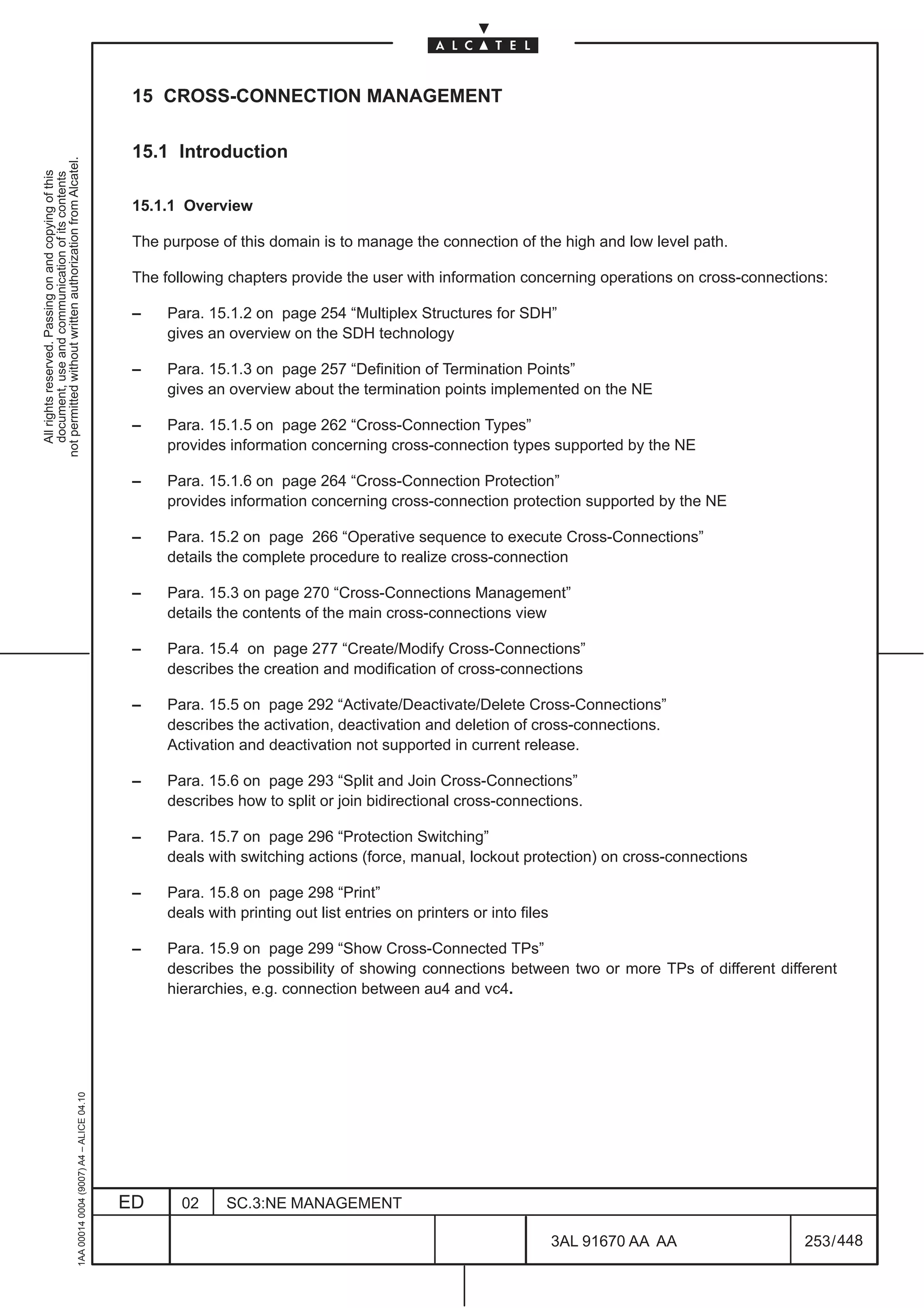

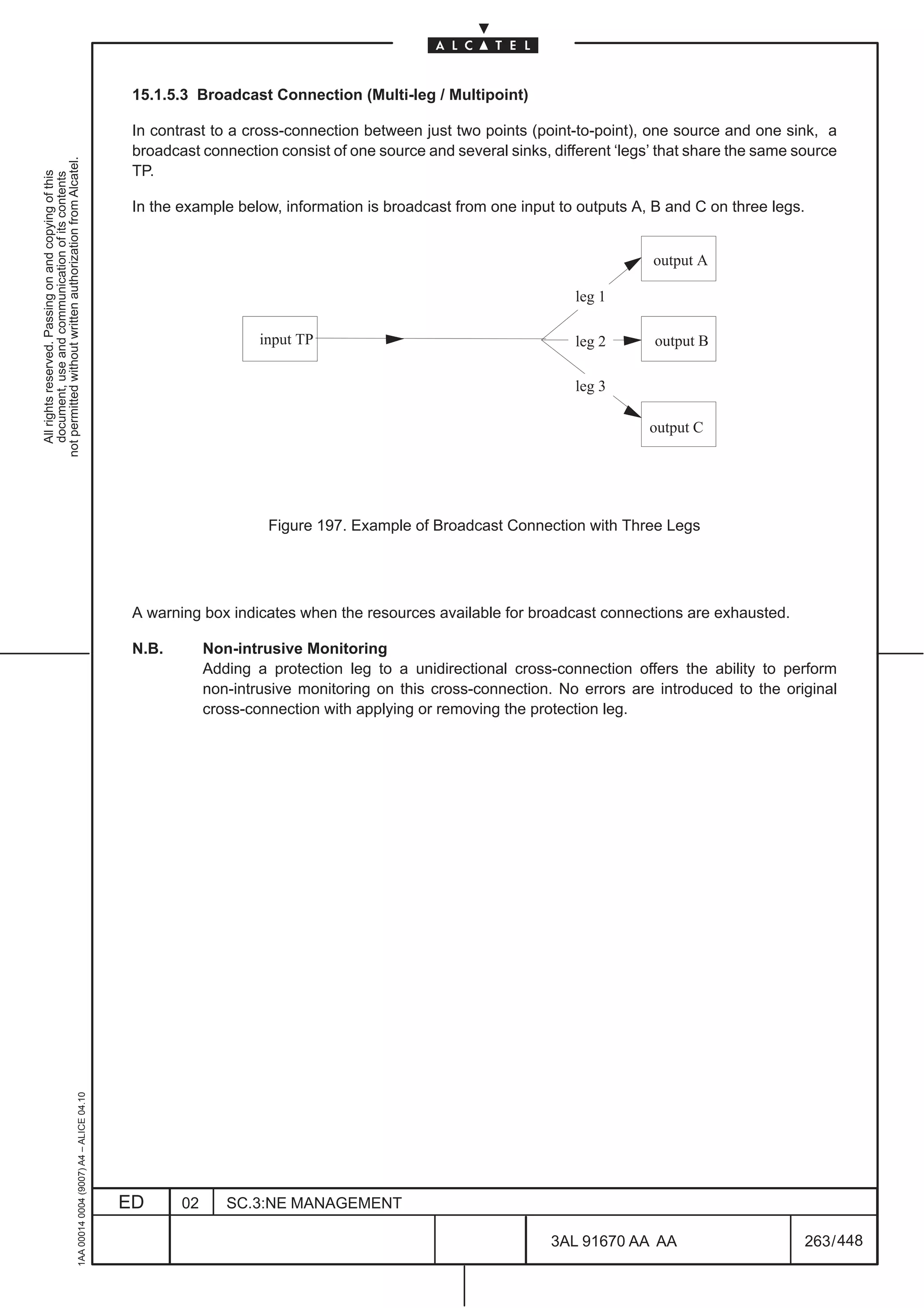
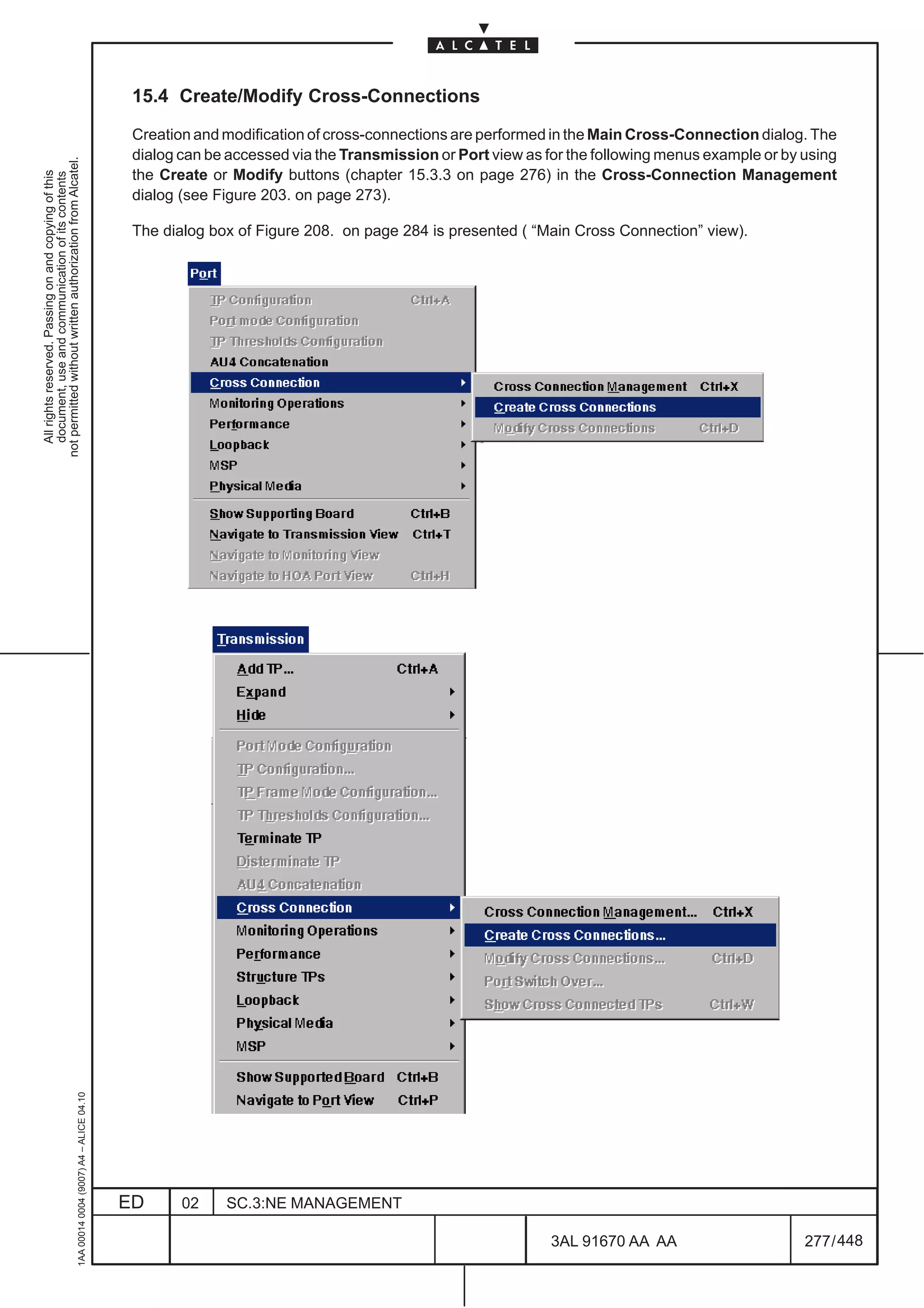
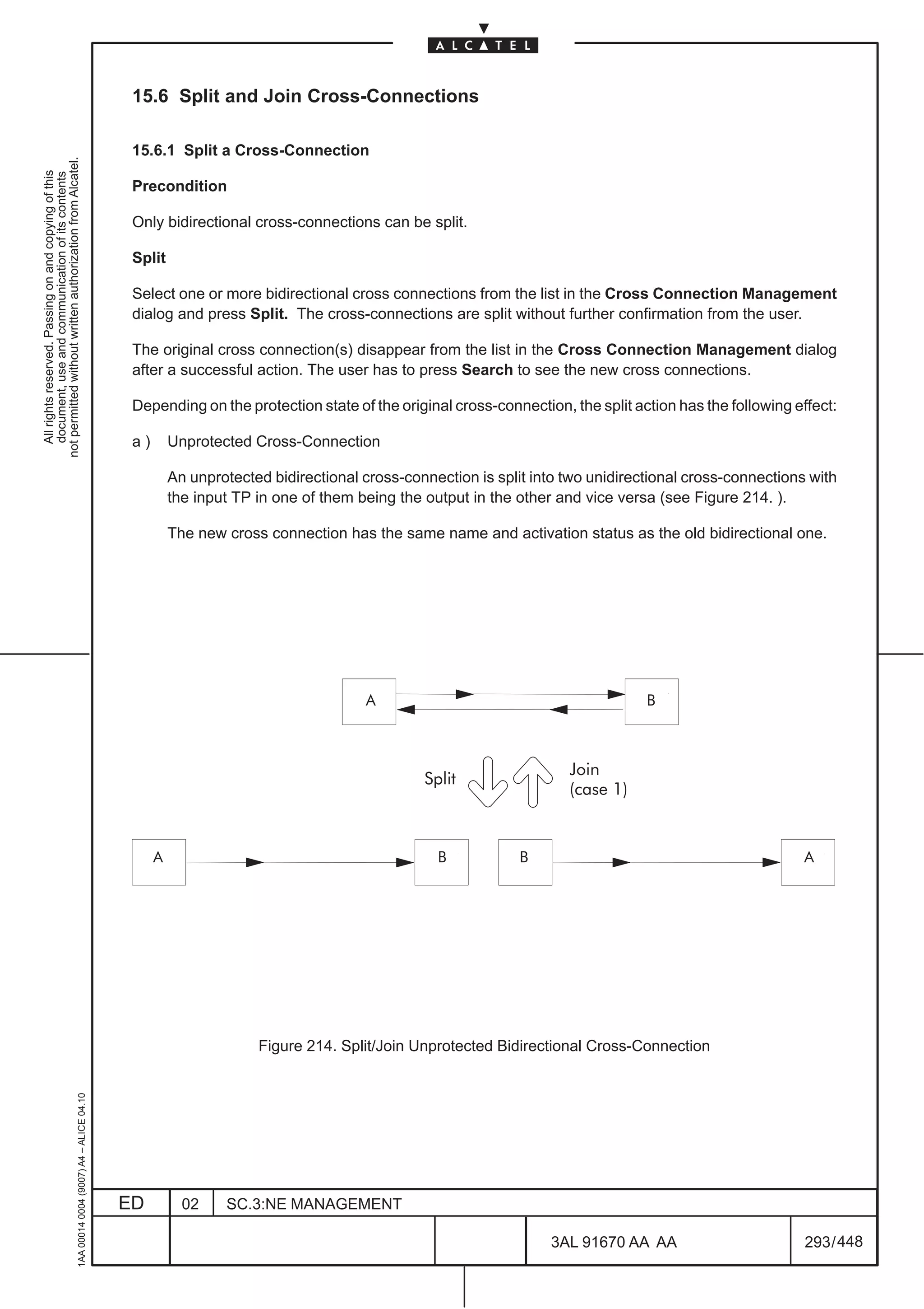
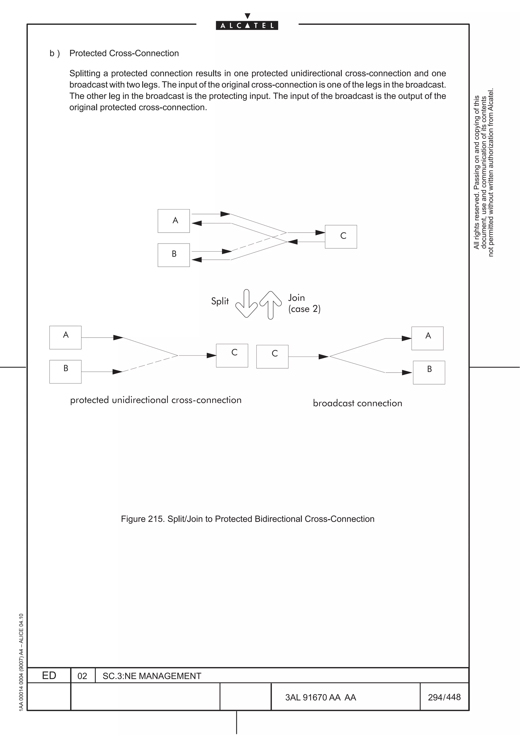
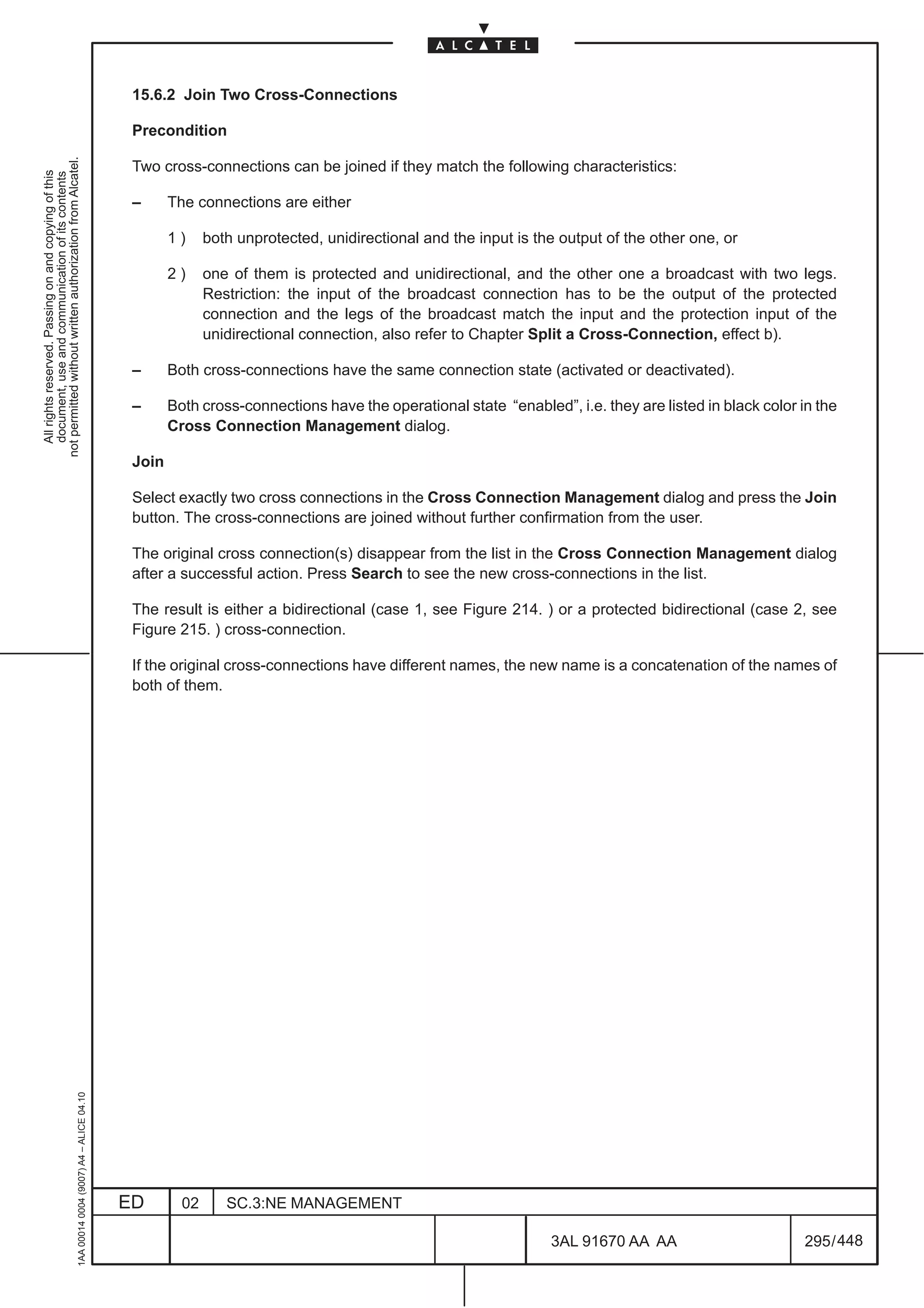
![15.2 Operative Sequence to execute Cross-Connections
This paragraphs list the complete procedure to realize some examples of cross-connection moving among
the various menus.
not permitted without written authorization from Alcatel.
All rights reserved. Passing on and copying of this
document, use and communication of its contents
The following main cases have been considered:
[1] High order signal cross connection (AU4s between SDH ports);
[2] High order concatenated signal cross connection (AU4–xc between SDH ports)
[3] Low order signal cross connection (TU12 cross connected with VC–12; ports involved: SDH and
PDH )
[4] 4XANY TPs cross connection (ports involved: 4XANY and SDH)
[5] ISA board TPs cross connection (ports involved:ISA, SDH or PDH)
[1] Procedure for high order signal (AU4)
In the following example an AU4 will be cross connected with another AU4; the P4S1N board has been
taken like reference board.
– In the subrack view click twice on the SDH port; the” board view” will be opened
– Click twice on the daughter board icon; the daughter view will be opened.
– Click twice on the SDH port icon present in the daughter view. the port view will be opened with all
the relevant TPs (SPI, RST, MST, MSP and AU4).
– Select the AU4 TP and then choose the Port –>Cross Connection –> Create Cross Connection option
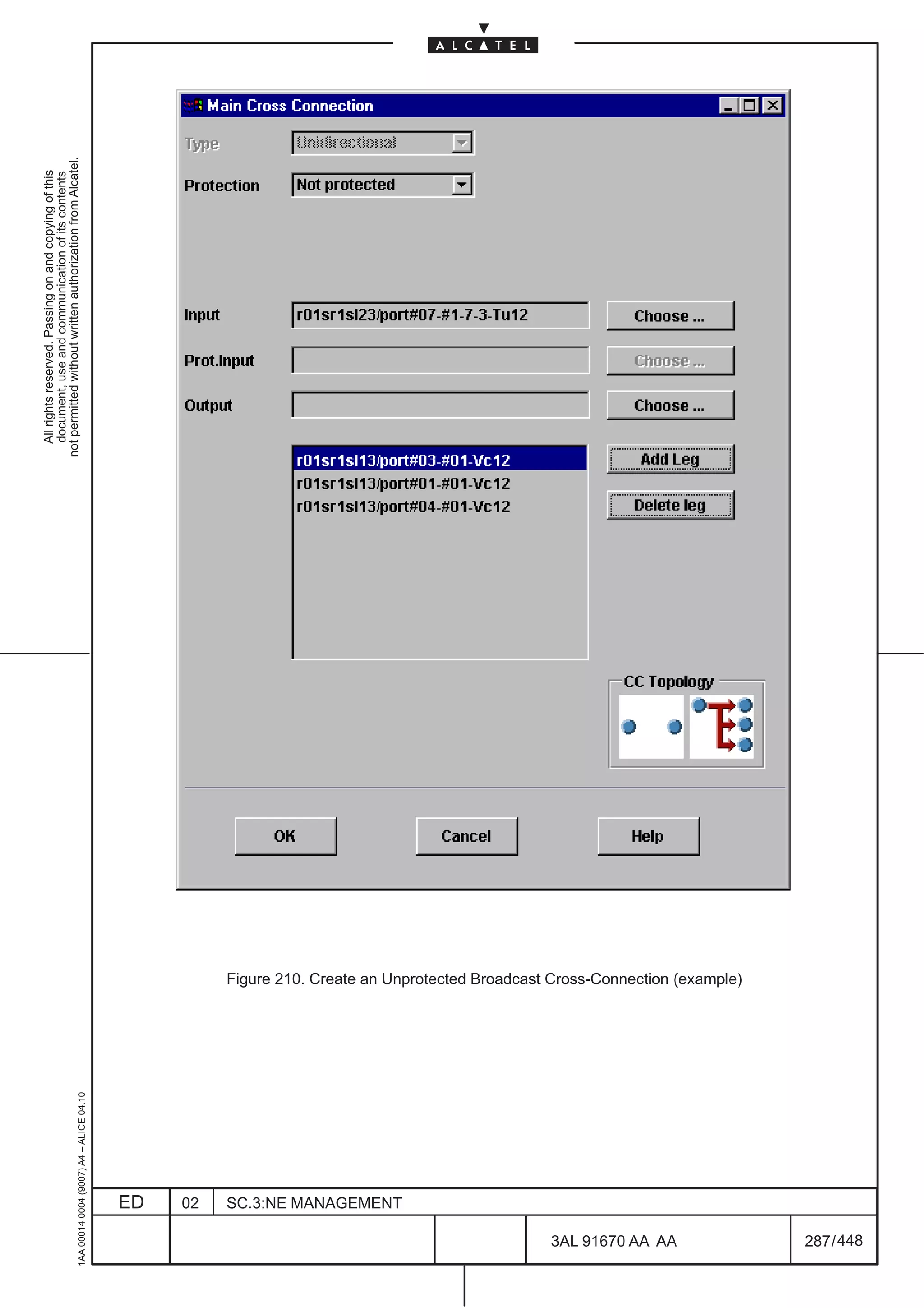
of the menu bar; a new window called ”Main Cross Connection” is opened.
• Select the correct value in the fields ”Type” and ”Protection”
• The “Input field” is automatically filled in
• Click on ”Choose” relevant to the ”Output” field; a new window called ”Search for Cross
Connection Output” is opened.
• On the ”Equipment” field select the Board (in our example is P4S1N), in the ”Termination Points”
field select the AU4
– Click on ”OK”; the ”Search for Cross Connection Output” window is closed.
– Repeat the same procedure as obove described for the ”Prot. Input” field for protected connections
– Click on ”OK” in the ”Main Cross Connection” window to terminate the creation.
– To check the presence of the new cross– connection select the Port –>Cross Connection –> Cross
Connection Management option of the menu bar; a new window called ”Coss connection
Management” will be opened
• Click on the “Search” button; all the cross connected Tp’s will be displayed in the “Cros
1AA 00014 0004 (9007) A4 – ALICE 04.10
Connection in list” field.
ED 02 SC.3:NE MANAGEMENT
3AL 91670 AA AA 266 / 448
448](https://image.slidesharecdn.com/1660smoperr4-452b-100224044515-phpapp01/75/1660-S-M-Oper-R4-314-2048.jpg)
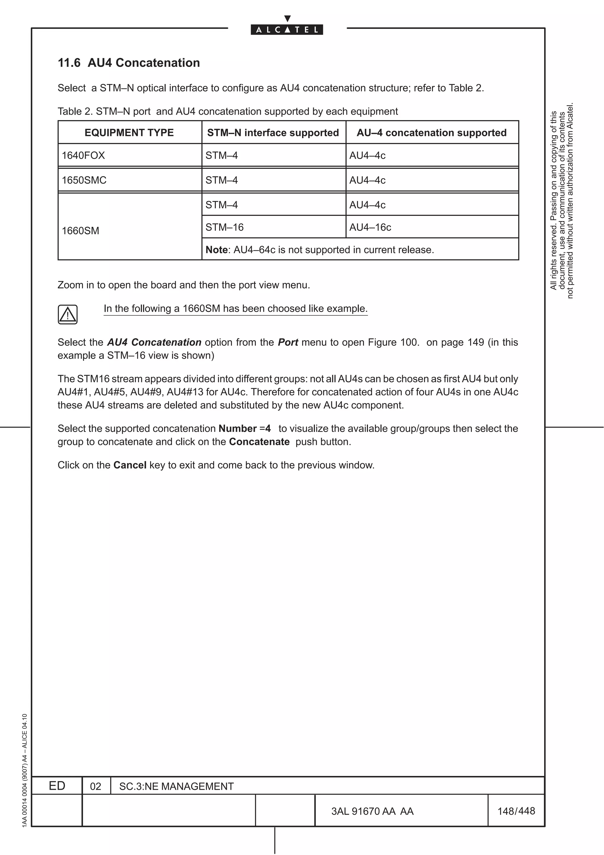
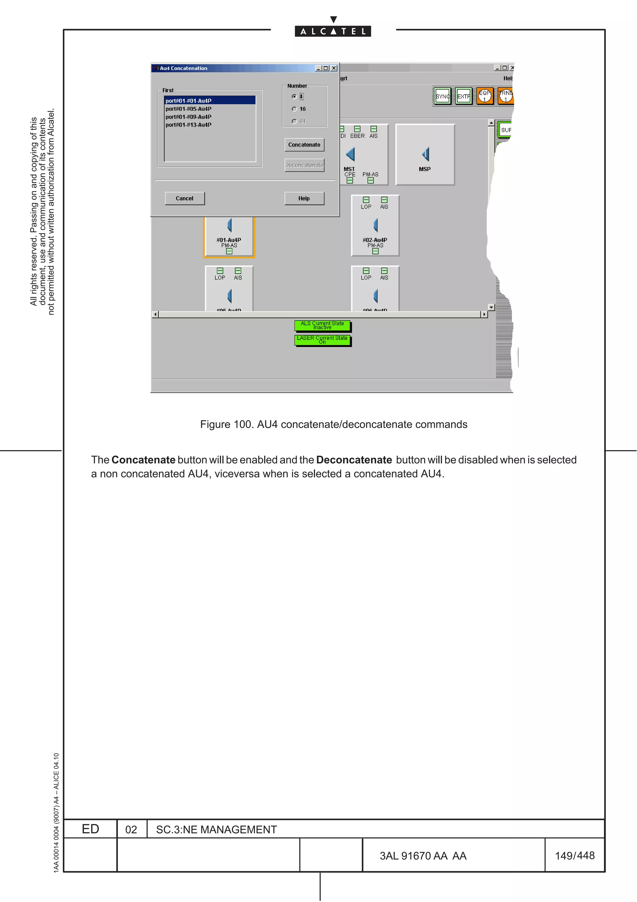
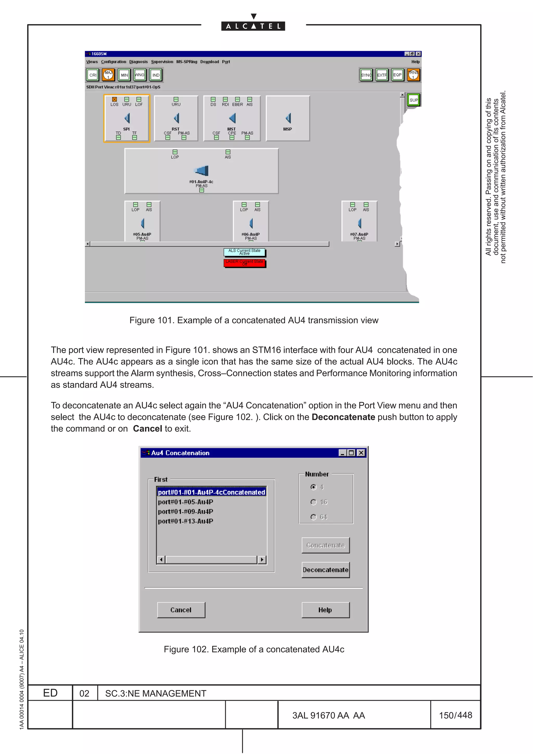
![[2] Procedure for AU4 concatenated (AU4–xC)
N.B. Before to create an AU4 concatenated cross–connection is necessary to define that the AU4s
on a STM–4 or STM–16 (the last only for 1660SM) board are concatenated as explained in para
not permitted without written authorization from Alcatel.
11.6 on page 148.
All rights reserved. Passing on and copying of this
document, use and communication of its contents
– In the subrack view click twice on the STM_N SDH port; the” board view” will be opened
– Click twice on the SDH port icon present in the board view. the port view will be opened with all the
relevant TPs (SPI, RST, MST, MSP and AU4–xC).
– Select the AU4–xC (with 4 X 16) TP and then choose the Port –Cross Connection – Create
Cross Connection option of the menu bar; a new window called ”Main Cross Connection” is opened.
• Select the correct value in the fields ”Type” and ”Protection”
• The “Input field” is automatically filled in
• Click on ”Choose” relevant to the ”Output” field; a new window called ”Search for Cross
Connection Output” is opened.
• On the ”Equipment” field select the STM–N Board , in the ”Termination Points” field select the
AU4–xC (with 4 X 16) (syntax example: r01sr1sl24/port#01–#01AU4P–4c ).
– Click on ”OK”; the ”Search for Cross Connection Output” window is closed.
– Repeat the same procedure as obove described for the ”Prot. Input” field for protected connections
– Click on ”OK” in the ”Main Cross Connection” window to terminate the creation.
– To check the presence of the new cross– connection select the Port –Cross Connection – Cross
Connection Management option of the menu bar; a new window called ”Coss connection
Management” will be opened
• Click on the “Search” button; all the cross connected Tp will be displayed in the “Cros
Connection in list” field.
[3] Procedure for low order signal (example TU12)
In the following example a VC–12 will be cross connected with a TU–12; the boards P4S1N and A21E1
has been taken like reference board for this example.
Note: the P4S1N STM–1 port payload must be structure as TU–12
– In the subrack view select Configuration – Cross Connection Management the” Cross Connection
Management” window will be opened.
– Click on the Create button; a new window called ”Main Cross Connection” is opened.
• Select the correct value in the fields ”Type” and ”Protection”
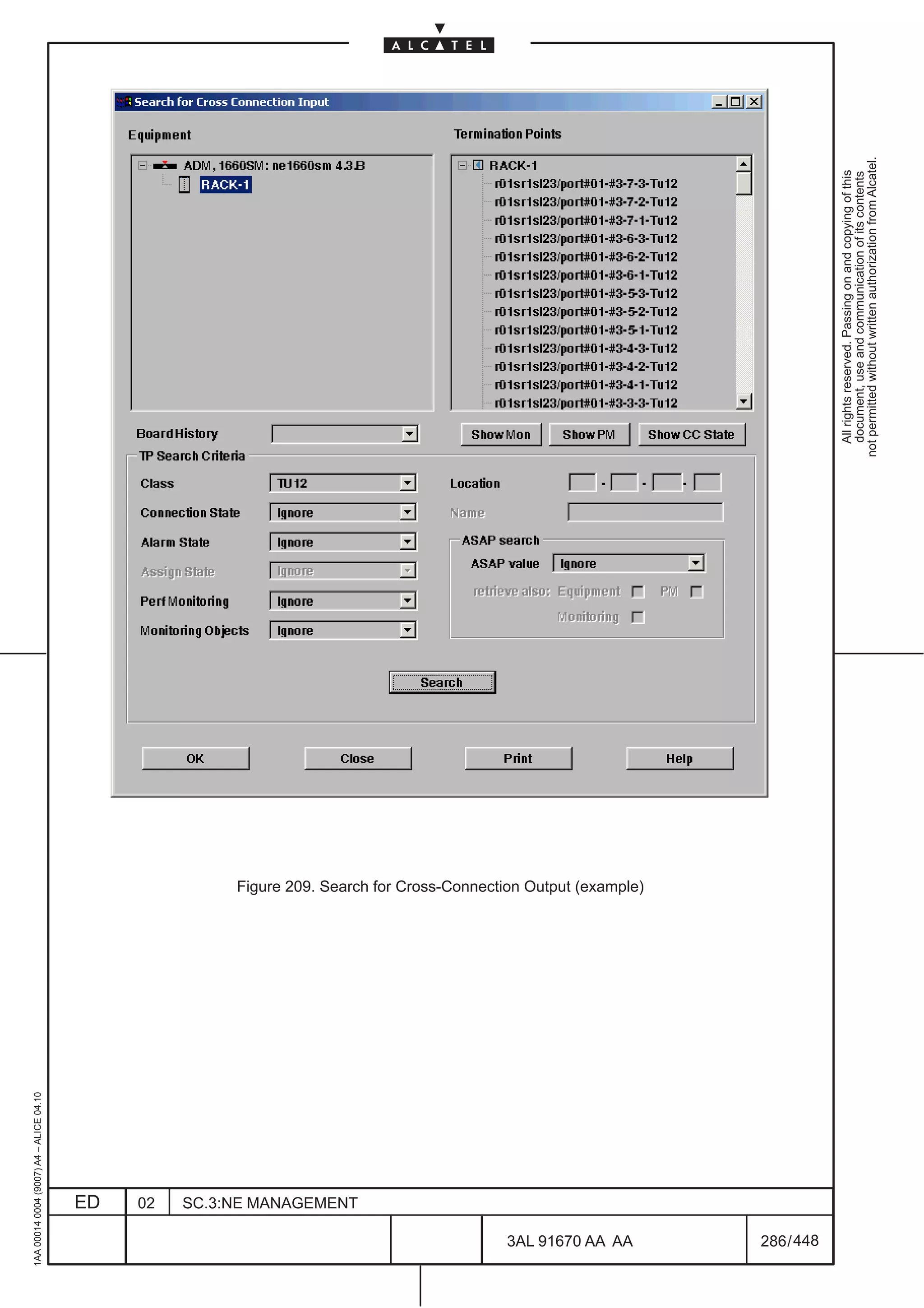
• Click on ”Choose” relevant to the ”Input” field; a new window called ”Search for Cross
Connection Input” is opened.
• On the ”Equipment” field select the Equipment Subrack (SR60M for 1660SM), in the “TP Seach
1AA 00014 0004 (9007) A4 – ALICE 04.10
Criteria” field select the TU12VC12, then click on search.
• In the Termination Point Field select the TU12 to be connected and subsequently click on OK
button; the ”Search for Cross Connection Input” window will be closed.
ED 02 SC.3:NE MANAGEMENT
3AL 91670 AA AA 267 / 448
448](https://image.slidesharecdn.com/1660smoperr4-452b-100224044515-phpapp01/75/1660-S-M-Oper-R4-315-2048.jpg)
![• Click on ”Choose” relevant to the ”Output” field and repeat the same sequence as above
described for the input point but instead of TU12 select now the VC12 to be connected in the
Termination Point Field; click on OK button AND the ”Search for Cross Connection Output”
window will be closed.
not permitted without written authorization from Alcatel.
All rights reserved. Passing on and copying of this
document, use and communication of its contents
– Select the VC–12 TP and then select the Port –Cross Connection – Create Cross Connection
option of the menu bar; a new window called ”Main Cross Connection” is opened.
• Select the correct value in the fields ”Type” and ”Protection”
• The “Input field” is automatically filled in
• Click on ”Choose” relevant to the ”Output” field; a new window called ”Search for Cross
Connection Output” is opened.
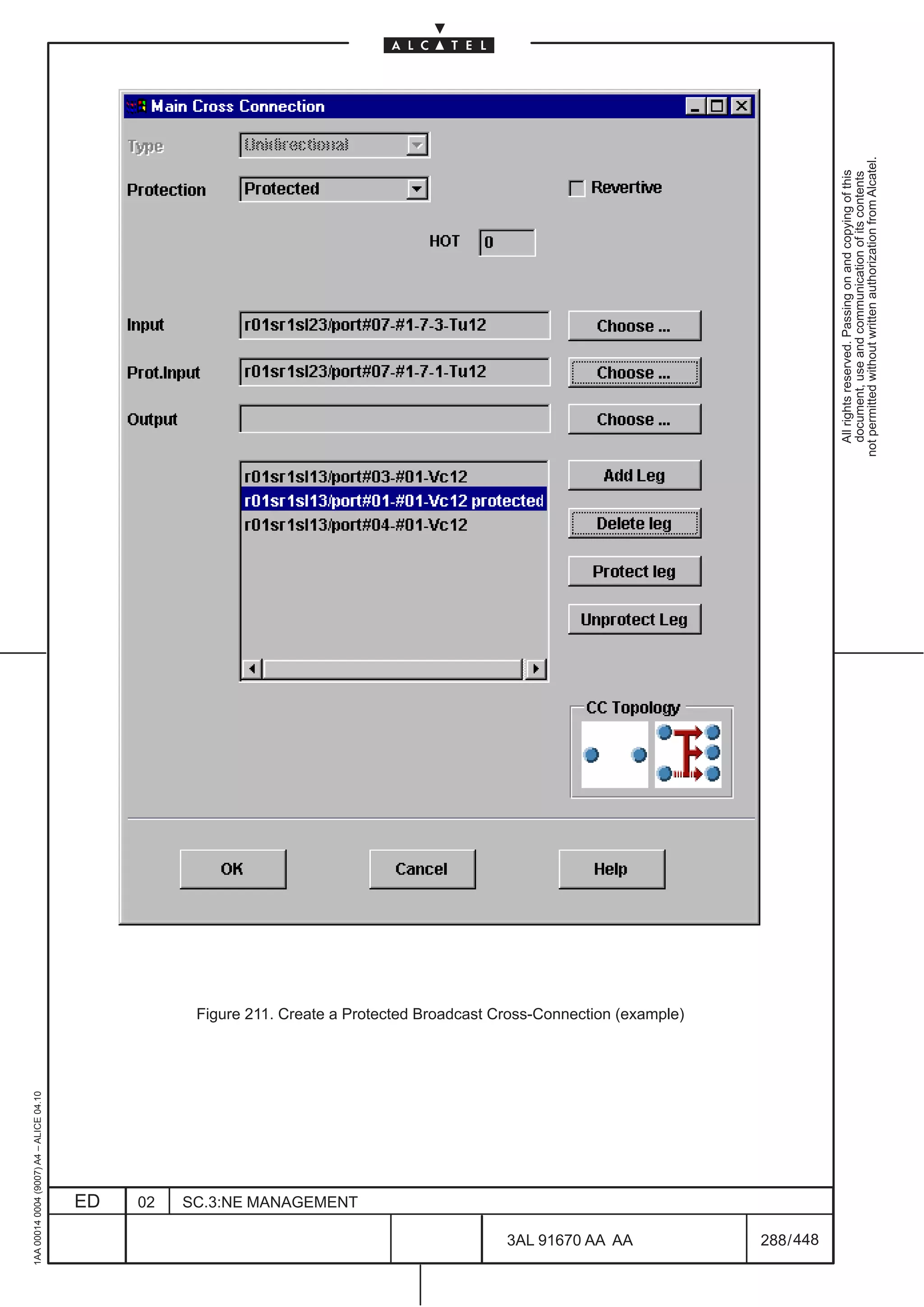
– Repeat the same on the ”Prot. Input” field for protected connections by selecting the TU12 involved
in the protection.
– Click on ”OK” in the ”Main Cross Connection” window to terminate the creation.
– To check the presence of the new cross– connection select the Port –Cross Connection – Cross
Connection Management option of the menu bar; a new window called ”Coss connection
Management” will be opened
• Click on the “Search” button; all the cross connected Tp will be displayed in the “Cros
Connection in list” field.
[4] 4XANY TPs cross connection
Note: before to create a cross connection the following step must be executed:
• configure the 4xANY board with the Equipment – Set menu
• configure the 4xANY MODULES with the Equipment – Set menu and choose the traffic type
that must be supported by the module (e.g. FICON, FDDI etc.); after having selected the traffic
type, automatically a number of TPs (VC–4) are generated for this port and can be viewed in
the port view. All the TPs must be used when the cross– connection will be created.
For details on 4xANY board refer to the Technical Handbook.
– In the subrack view click twice on the 4xANY board; the” board view” will be opened .
– Click twice on the module to be used; the daughter view will be opened
– Click twice on the daughter board icon; the port view will be opened with all the relevant TPs.
In the following will be explained how to connect one TpP of the 4XANY; repeat the same sequence for
all the TPs that has been generated when the traffic type has been defined.
– Select the VC–4 TP and then choose the Port –Cross Connection – Create Cross Connection
option of the menu bar; a new window called ”Main Cross Connection” is opened.
• Select the correct value in the fields ”Type” and ”Protection”
• The “Input field” is automatically filled in
•
1AA 00014 0004 (9007) A4 – ALICE 04.10
Click on ”Choose” relevant to the ”Output” field; a new window called ”Search for Cross
Connection Output” is opened.
ED 02 SC.3:NE MANAGEMENT
3AL 91670 AA AA 268 / 448
448](https://image.slidesharecdn.com/1660smoperr4-452b-100224044515-phpapp01/75/1660-S-M-Oper-R4-316-2048.jpg)
![• On the ”Equipment” field select the Board to be used for the connection with the 4XANY board
(for example S4.1N), in the ”Termination Points” field select the AU4
– Click on ”OK”; the ”Search for Cross Connection Output” window is closed.
not permitted without written authorization from Alcatel.
All rights reserved. Passing on and copying of this
document, use and communication of its contents
– Click on ”OK” in the ”Main Cross Connection” window to terminate the creation.
– repeat the same procedure for all the VC–4 generated for the specific traffic type associated to the
4xANY module.
– To check the presence of the new cross–connection select the Port –Cross Connection – Cross
Connection Management option of the menu bar; a new window called ”Coss connection
Management” will be opened
• Click on the “Search” button; all the cross connected Tp will be displayed in the “Cros
Connection in list” field.
[5] ISA board TPs cross connection
Note: before to create a cross connection the following step must be executed:
• configure the ISA board with the Equipment – Set menu
• define the TP that must be created on the ISA board by selecting the Configuration – ISA Port
Configuration menu (refer to Chapter 20 for details)
– The ISA board TP cross– connection is similar to that described for the 4xANY board so refer to point
[4] .
1AA 00014 0004 (9007) A4 – ALICE 04.10
ED 02 SC.3:NE MANAGEMENT
3AL 91670 AA AA 269 / 448
448](https://image.slidesharecdn.com/1660smoperr4-452b-100224044515-phpapp01/75/1660-S-M-Oper-R4-317-2048.jpg)
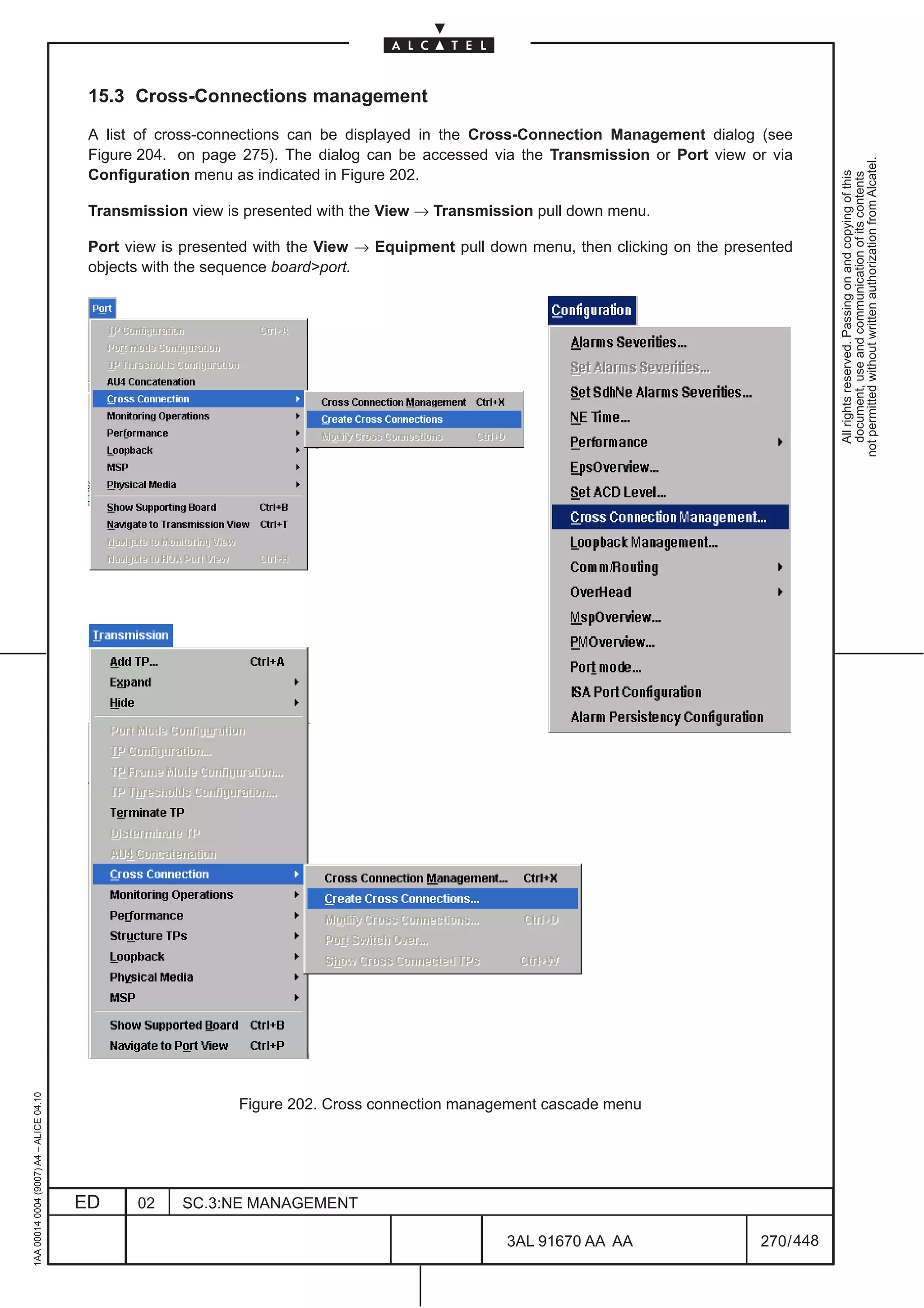

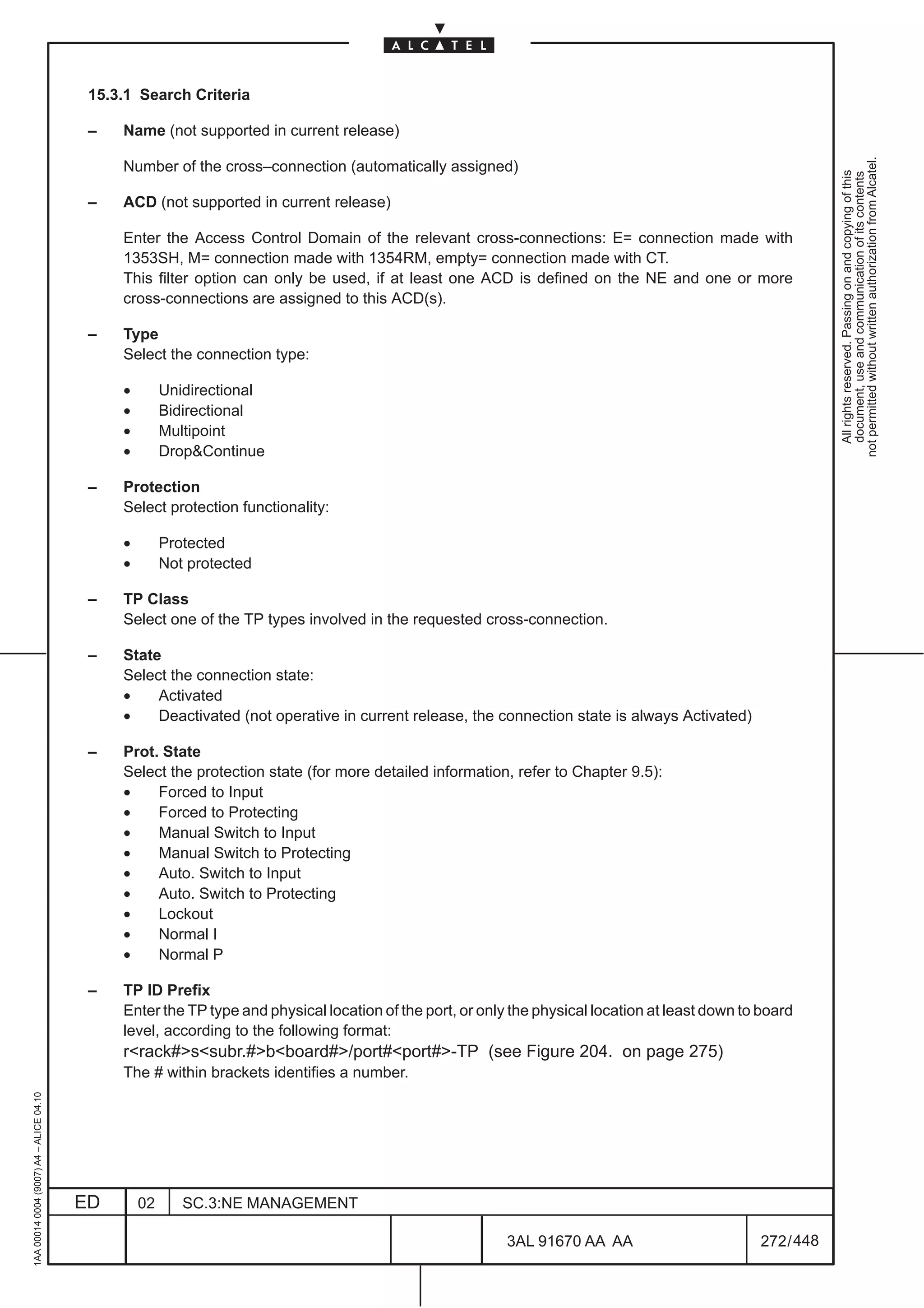
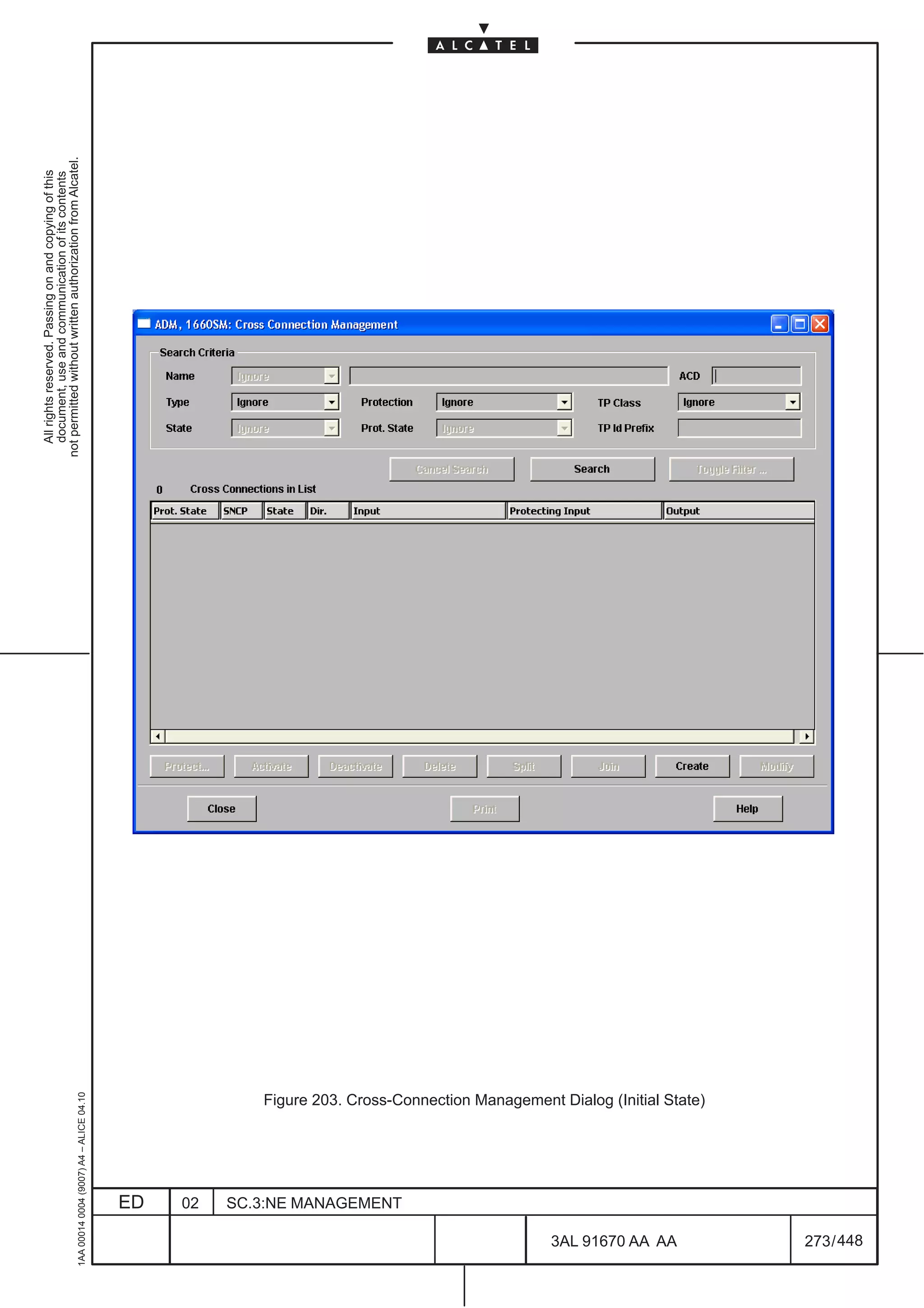
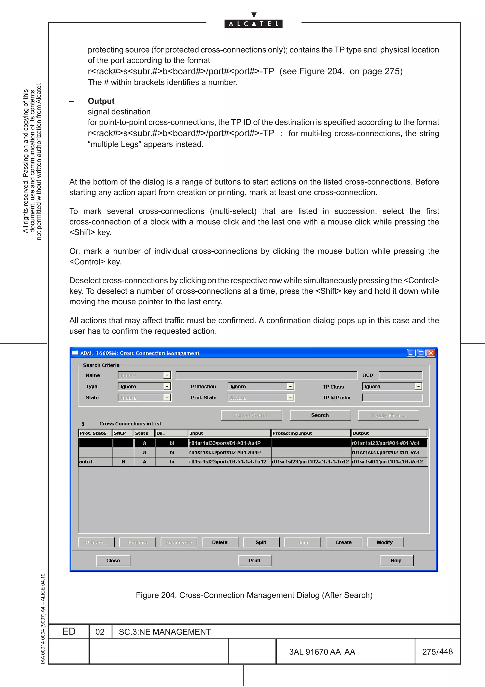
![15.3.2 Cross-Connection List
After a successful search, a read only list of cross-connections matching the search criteria appears
(see Figure 204. ). The number of matching cross-connections is displayed in the upper left corner of the
not permitted without written authorization from Alcatel.
list. The list contains information concerning the following parameters for each cross-connection:
All rights reserved. Passing on and copying of this
document, use and communication of its contents
– Prot. State
detailed switching information in the format:
protection state traffic ind (location:signal state–switch status,
[location:signal state–switch status])
• protection state
Normal, Auto, Lockout, Forced or Manual.
• traffic ind
indicates the location of current traffic:
P (Protecting input) or I (Input).
• location
indicates the location of the errored signal:
P (Protecting input) or I (Input)
• signal state
indicates the signal state: SD (Signal Degrade) or SF (Signal Failure)
• switch status
status of the switch:
c (completed) or p (pending)
Example:
Auto I (P:SD-c)
There has been an Automatic switch from the protecting input to the Input where the traffic is
currently located. The reason for the automatic switch was Signal Degrade in the Protecting input.
The switch was completed.
– SNCP
Protection type indication I ( Inherently monitored Sub–Netwok Protection) or N (Non–intrusively
Sub_Network Connection Protection)
– State
connection state indicating whether cross-connection is A(ctivated) or D(eactivated)
– Dir.
Direction-related connection type:
uni(directional), bi(directional), mp (multipoint), DC_N (Drop Continue Normal) or DC_I (Drop
Continue Inverse)
– Input
signal source; contains the TP type and physical location of the port according to the format
rack#–subr.#–board#–port#,port##TP (see Figure 204. on page 275)
1AA 00014 0004 (9007) A4 – ALICE 04.10
The # within brackets identifies a number.
– Protecting Input
ED 02 SC.3:NE MANAGEMENT
3AL 91670 AA AA 274 / 448
448](https://image.slidesharecdn.com/1660smoperr4-452b-100224044515-phpapp01/75/1660-S-M-Oper-R4-322-2048.jpg)

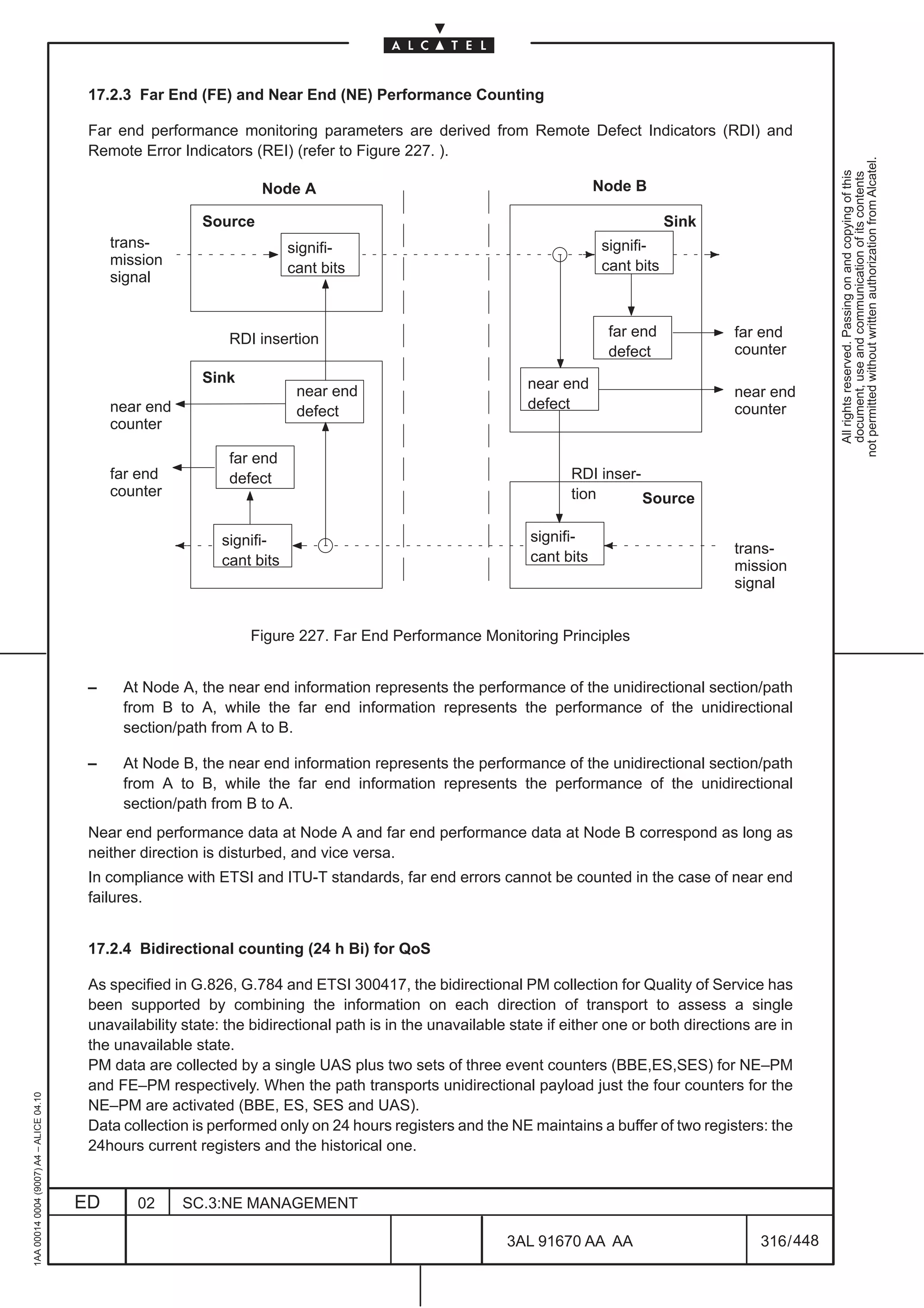
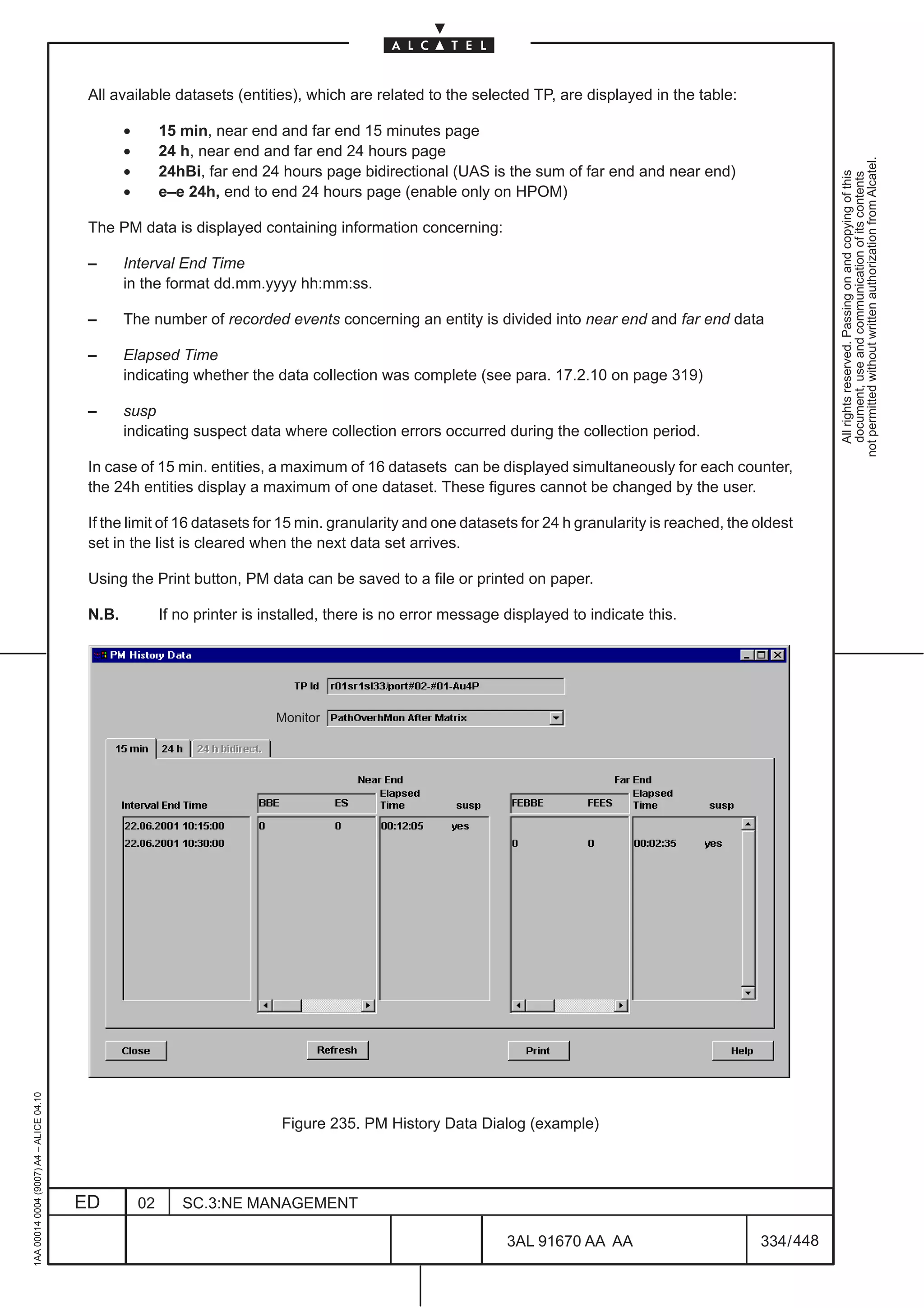
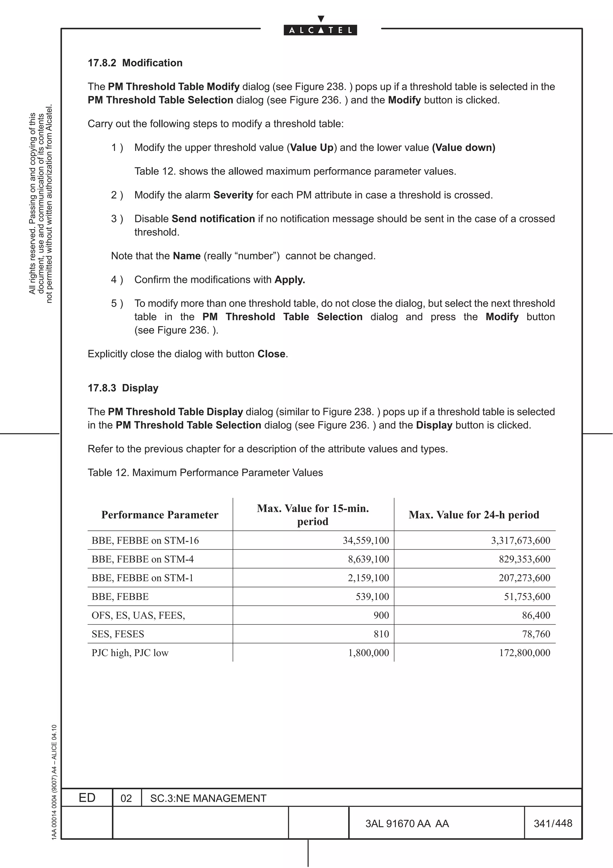
![– Far End Unavailable Second (FEUAS): An Unavailable Second is a second which is part of the
Unavailable Time at the far end.
The Termination Point (TP) type determines which performance monitoring events can be counted:
not permitted without written authorization from Alcatel.
All rights reserved. Passing on and copying of this
document, use and communication of its contents
– SDH TPs
Both near end and far end counters are supported in receive direction of the signal for all SDH path
layers and for the multiplex section layer. For the regenerator section, no far end information is
transmitted and, therefore, only near end counting is supported.
– PDH TPs
Only near end counters are supported in receive direction for all PDH path layers.
Further definitions:
– Errored Block (EB): A block in which one or more bits associated with the block are erroneous.
– Remote Error Indicator (REI) [formerly Far End Block Error (FEBE)] : Identifies, at a terminal,
the count of errored blocks that were received by the far end terminal.
– Remote Defect Indicator (RDI) [formerly Far End Receive Failure (FERF)]: indicates to a terminal
that the far end terminal has detected an incoming failure.
– Unavailable Time (UAT): A period of unavailable time begins at the onset of 10 consecutive SES
events. These 10 seconds are considered to be part of unavailable time. A new period of available
time begins at the onset of 10 consecutive non-SES events.
– Pointer Justification Event (PJE): A PJE is an inversion of I– or D– bits of the pointer , together
with an increment or decrement of the pointer value to signify a frequency justification.
– Out of Frame Second (OFS) ): An OFS is defined as a second in which one or more out of frame
events have occurred. This event is identified by the A1/A2 byte of the SDH Frame.
The counting of OFS is only supported for the regenerator section termination. Please note that this
counter is deprecated by ETSI and will be removed from international standards.
1AA 00014 0004 (9007) A4 – ALICE 04.10
ED 02 SC.3:NE MANAGEMENT
3AL 91670 AA AA 315 / 448
448](https://image.slidesharecdn.com/1660smoperr4-452b-100224044515-phpapp01/75/1660-S-M-Oper-R4-363-2048.jpg)
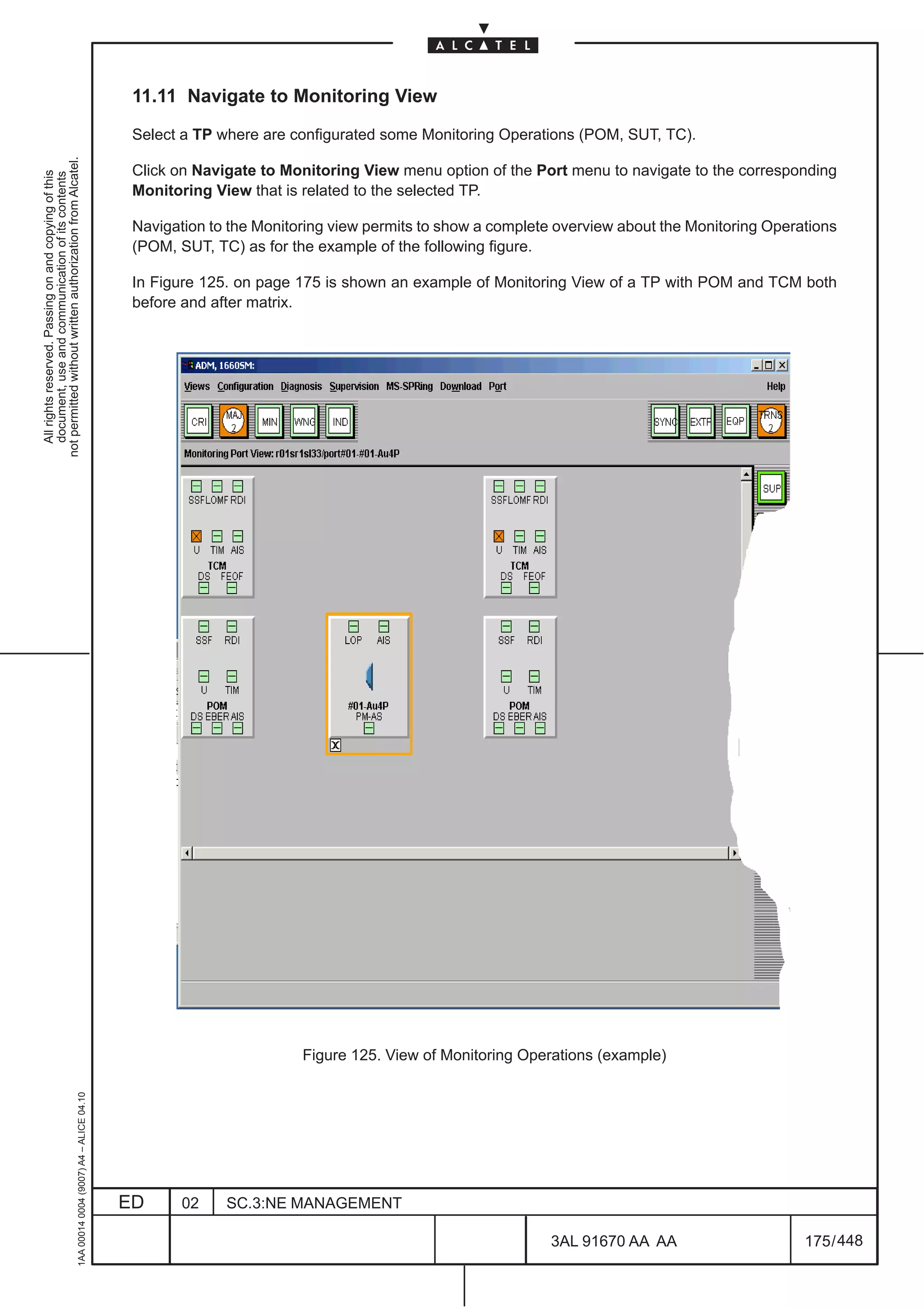
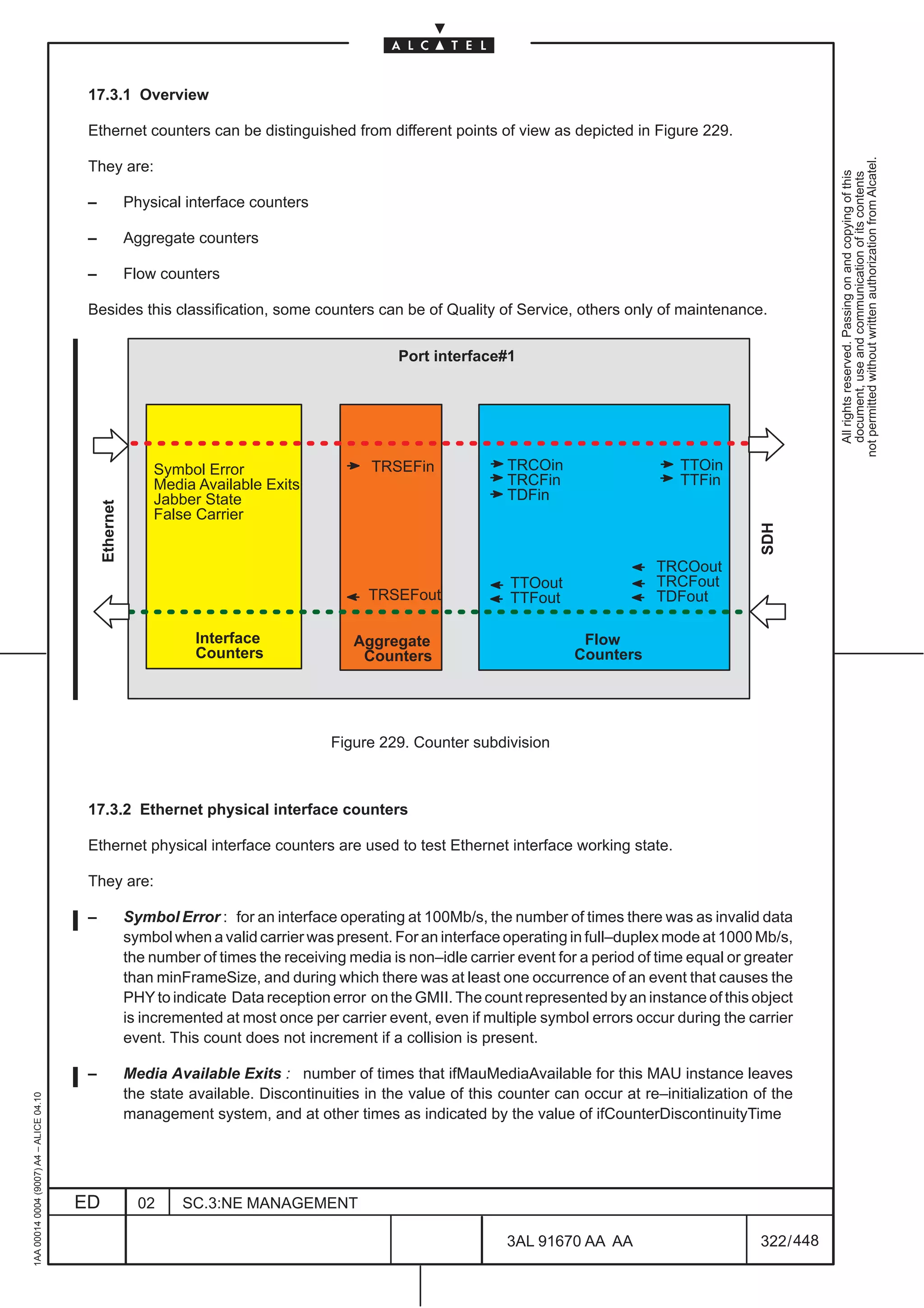
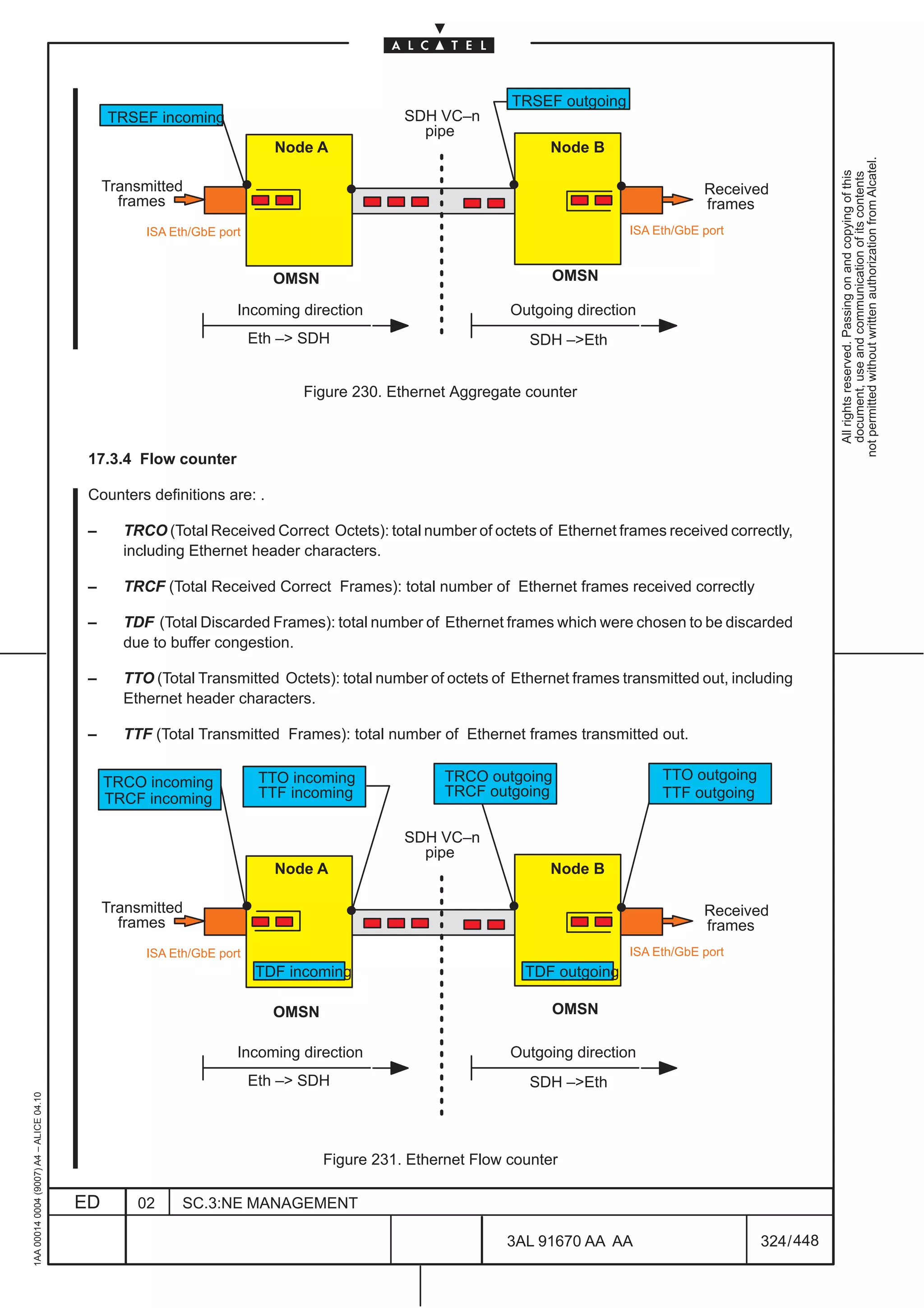
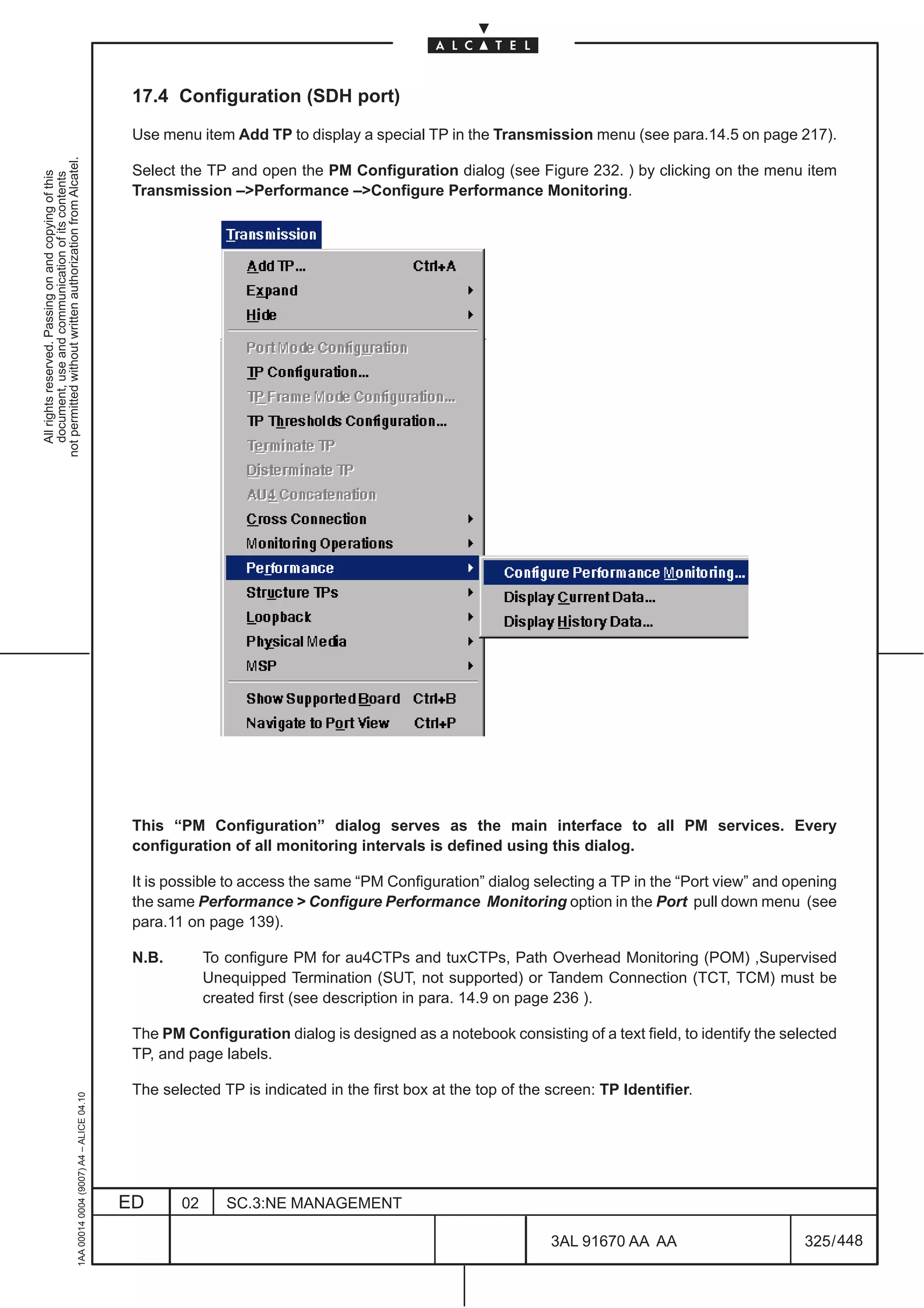
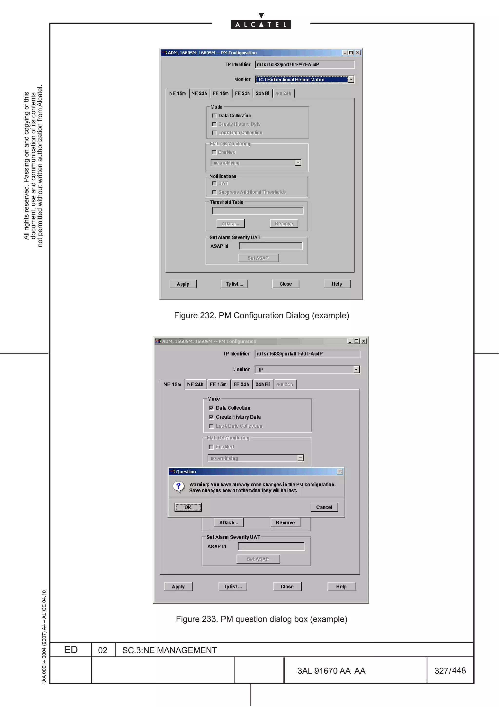
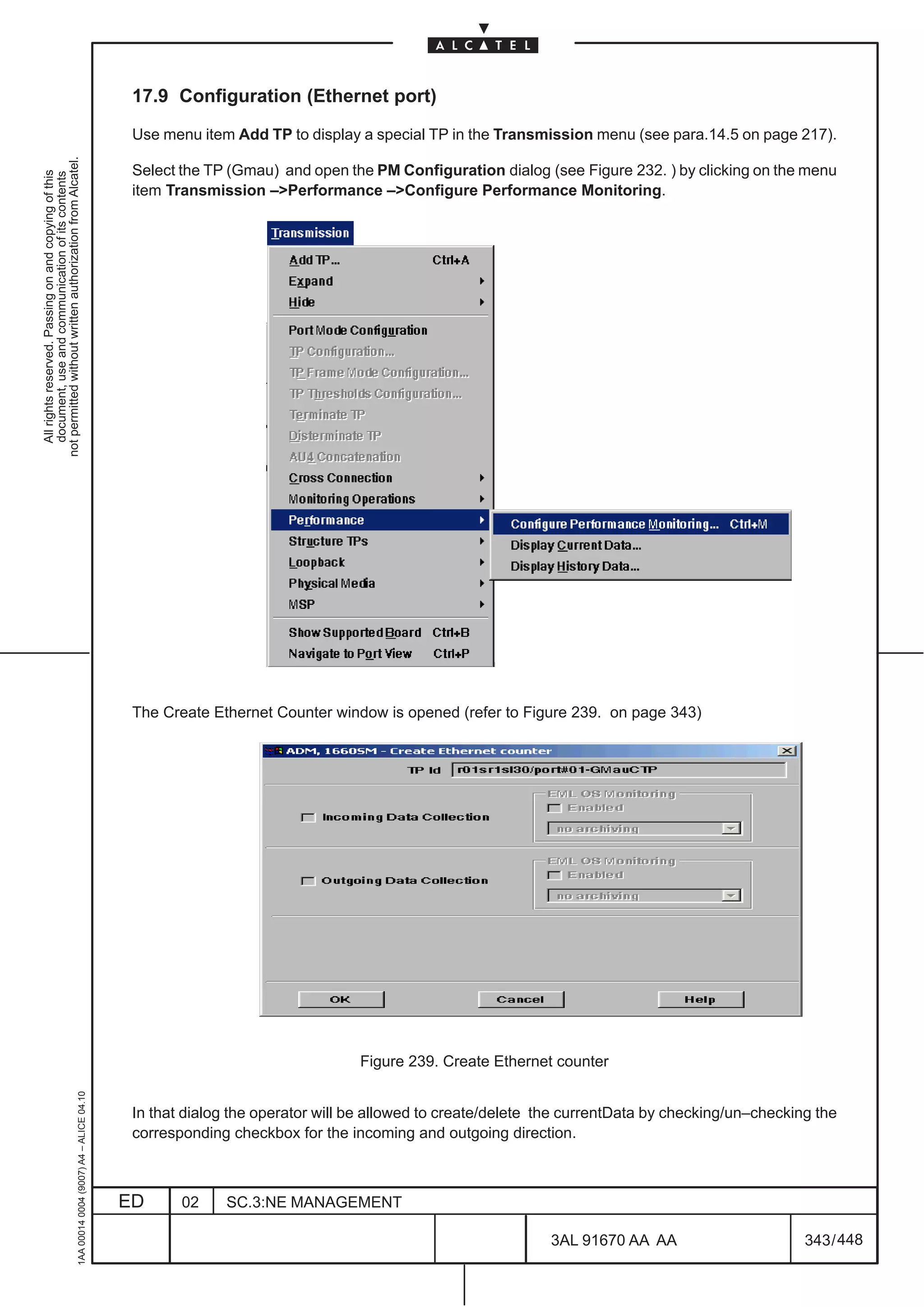
![17.3 Performance Monitoring on ETHRNET port
Performance Monitoring on Ethernet port, can be applied to ETH–ATX, GETH–AG, ETH–MB, GETH–MB
cads and are described in the following paragraphs:
not permitted without written authorization from Alcatel.
All rights reserved. Passing on and copying of this
document, use and communication of its contents
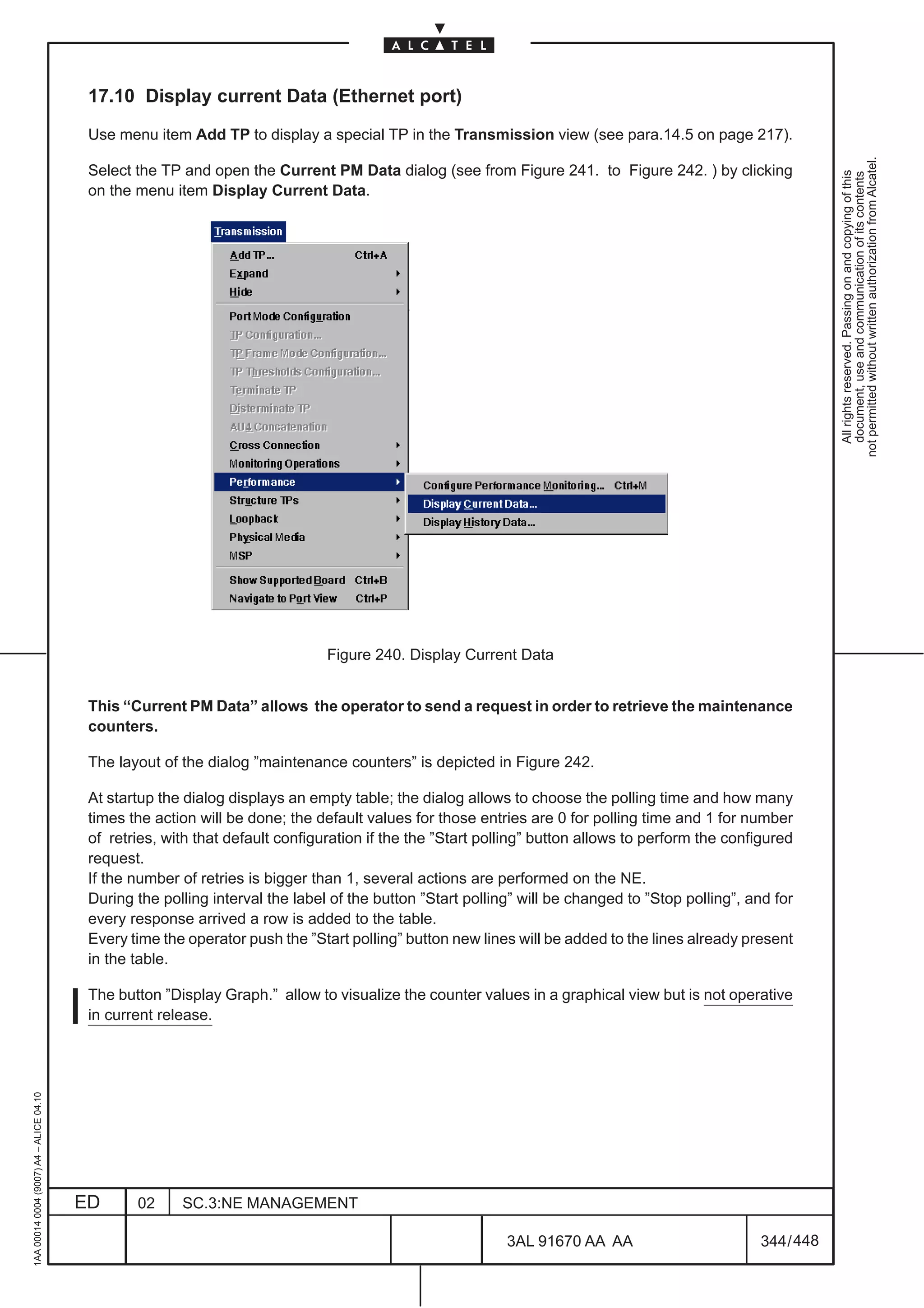
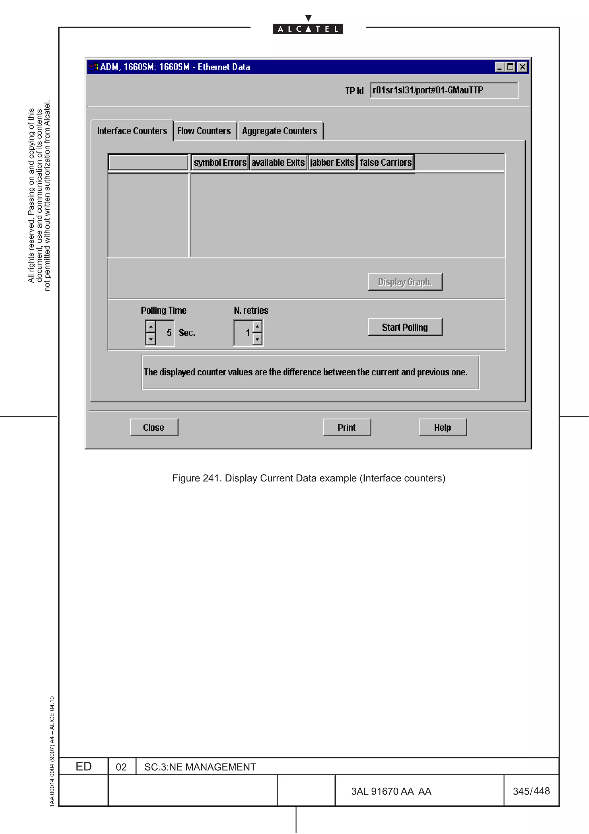
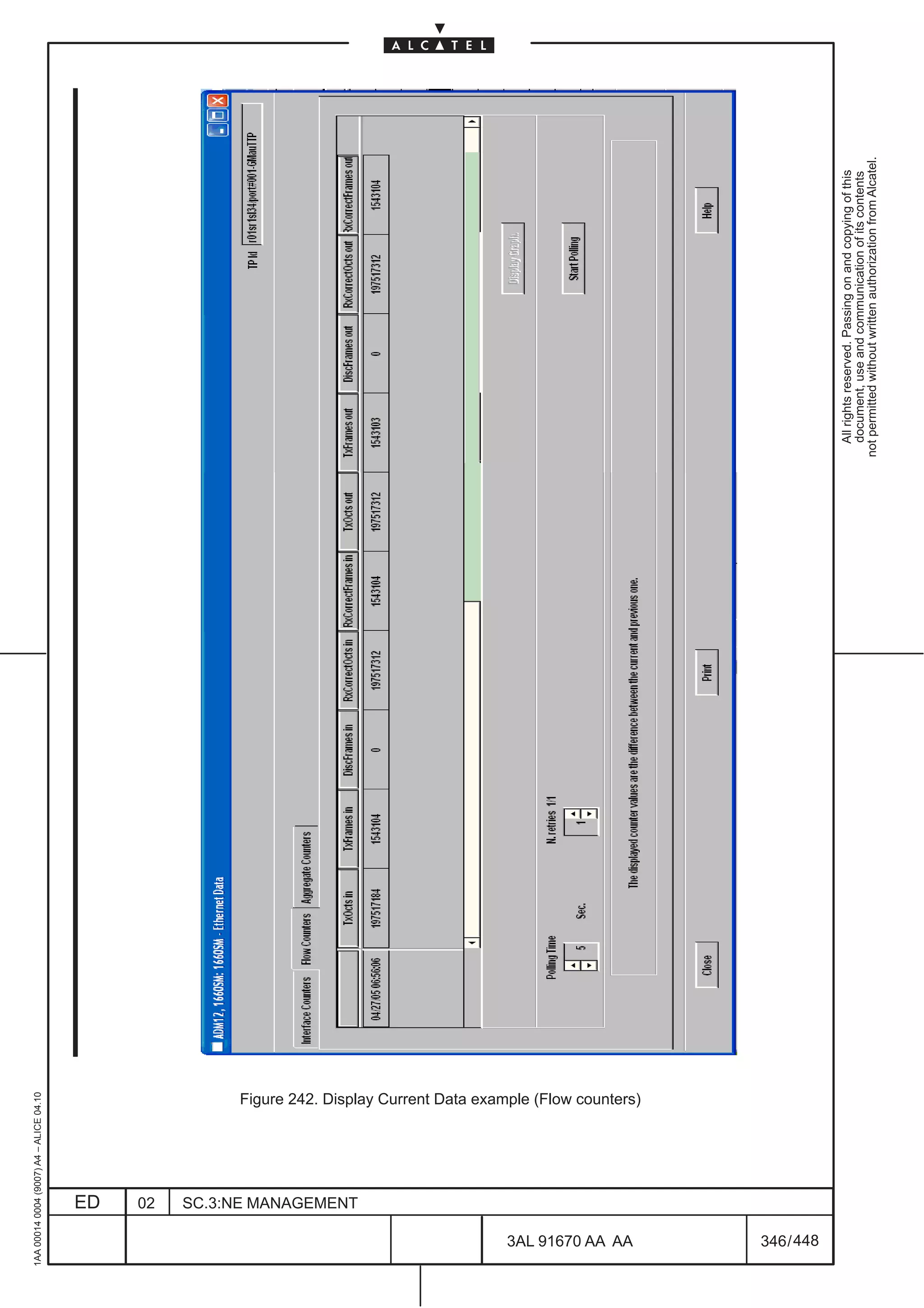
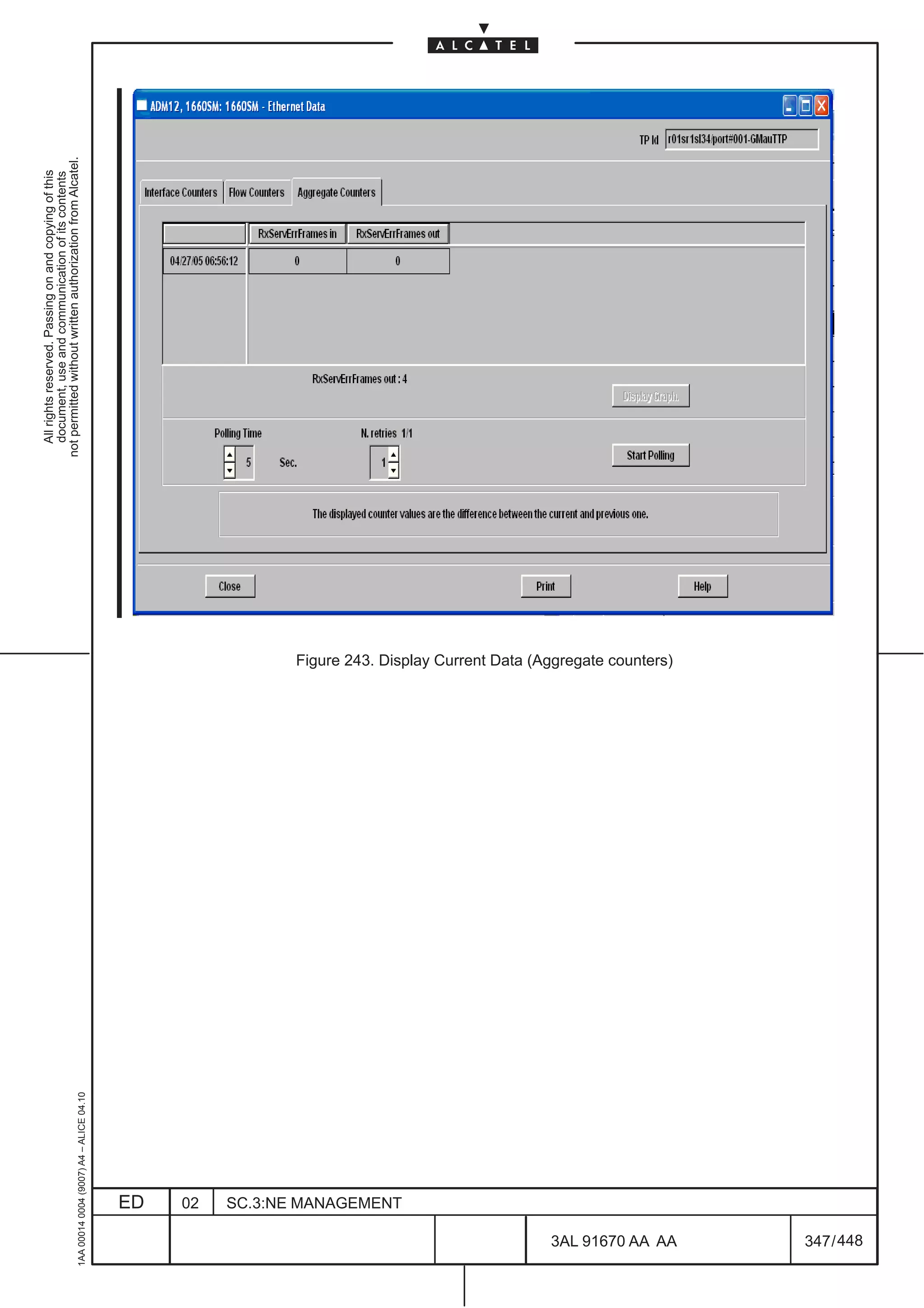
– Paragraph 17.9 on page 343 Configuration (Ethernet port) deals with the configuration of
performance monitoring
– Paragraph 17.10 on page 344 Display Current Data (Ethernet port) deals with displaying current
performance data
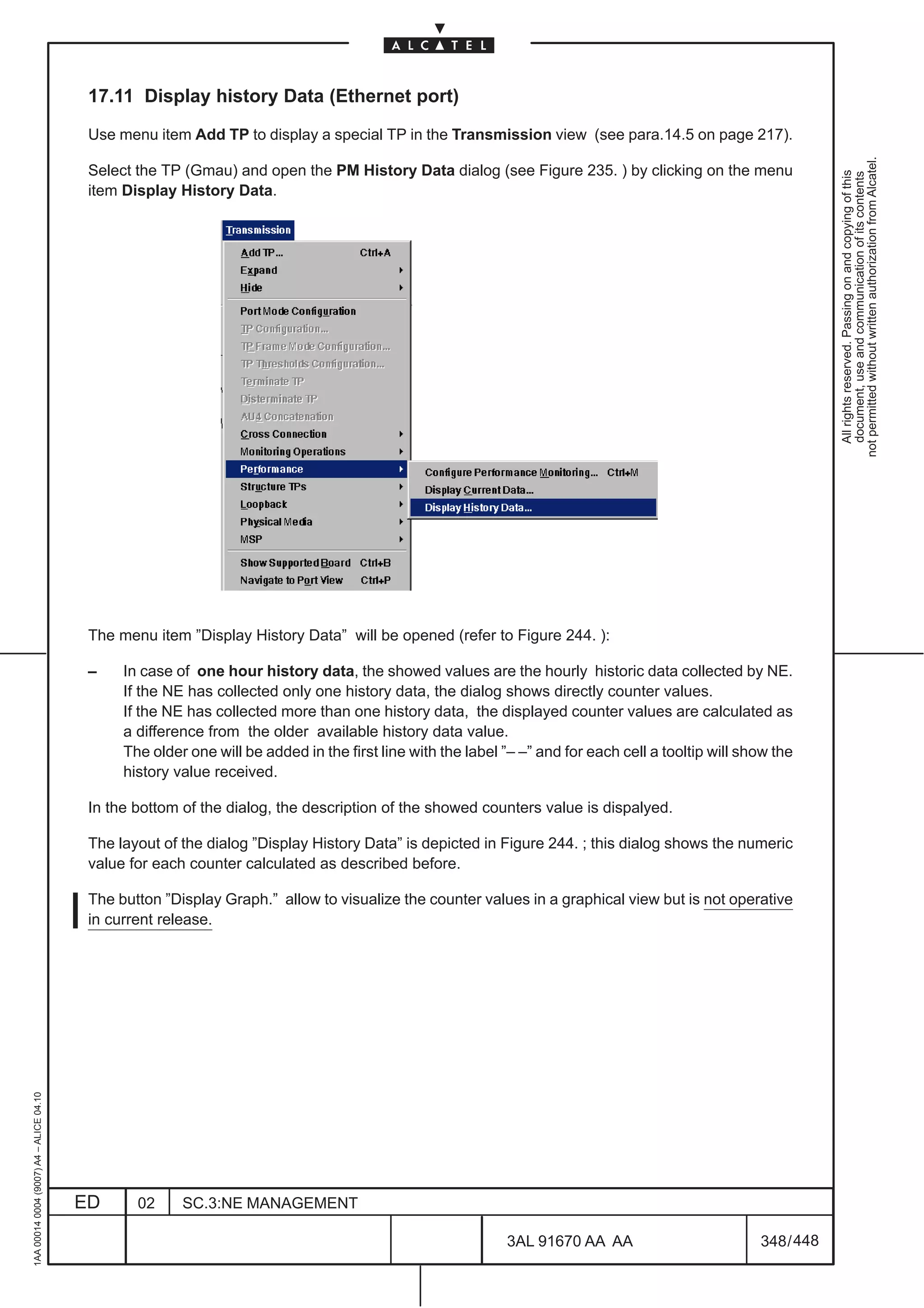
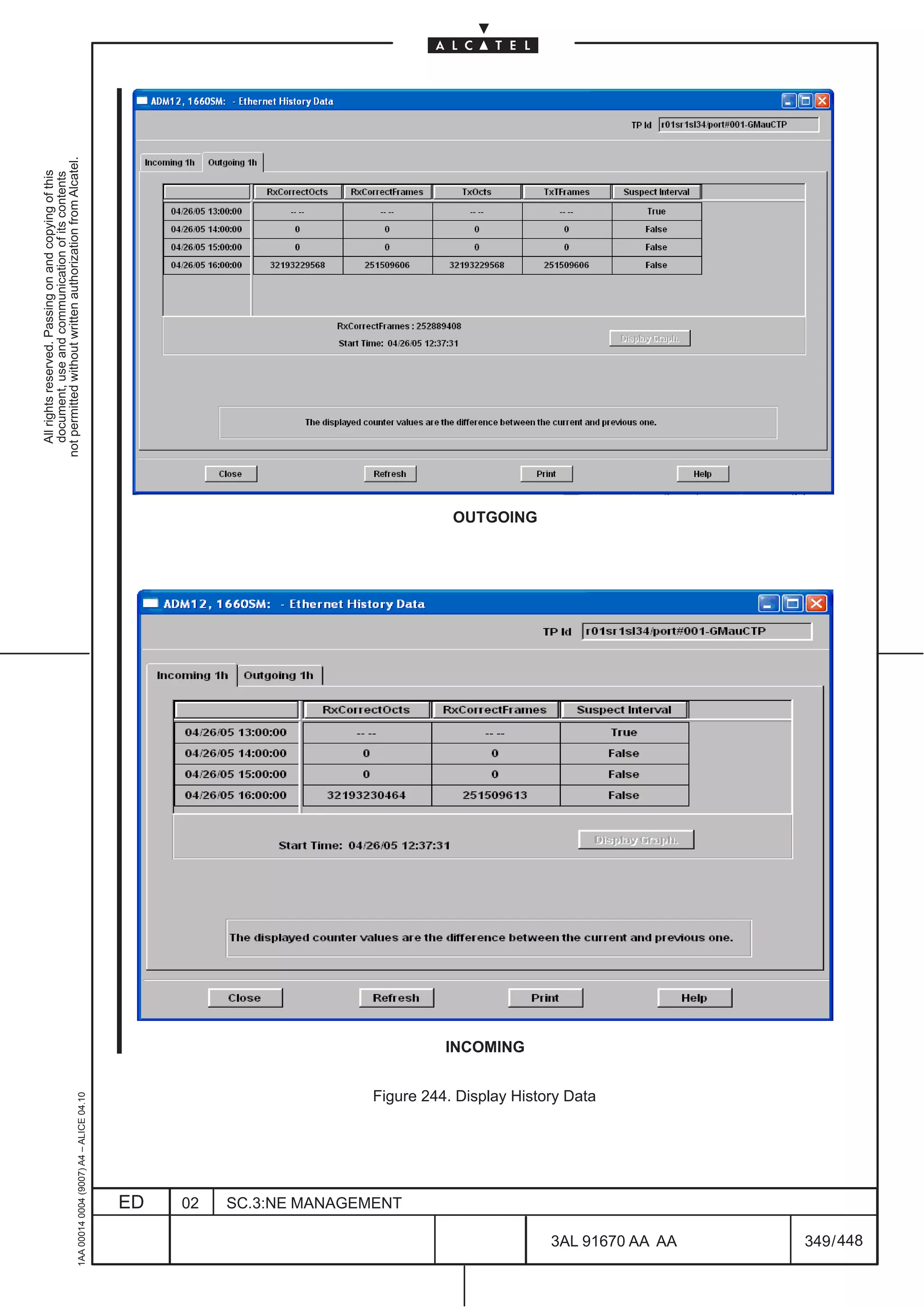
– Paragraph 17.11 on page 348 Display History Data (Ethernet port) deals with displaying history
performance data
An Ethernet link can be defined between two 10/100 Ethernet interfaces, or between two Gb Ethernet
interfaces, or also between a Fast Ethernet and a Gb Ethernet interface.
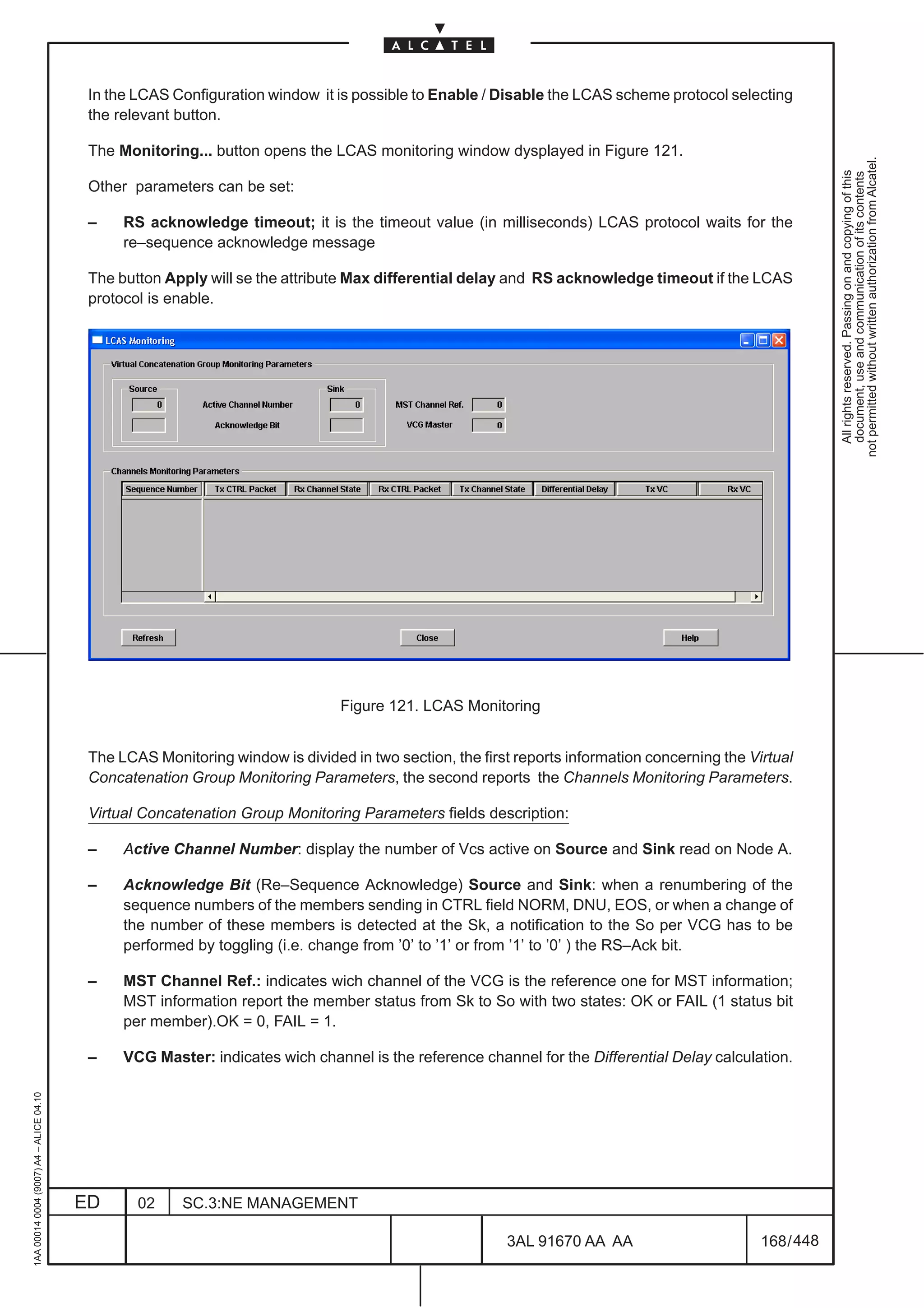
At the terminations of Ethernet link, it s possible to monitor the Ethernet frames and to collect information
about the Ethernet traffic by means of some counters.
Definitions of incoming and outgoing counter direction
[1] Incoming (network centric view): it refers to the direction starting from Ethernet domain toward SDH
domain (see Figure 228. ). The traffic arrives to the board from an Ethernet link and goes out from
an SDH link.
[2] Outgoing (network centric view): it refers to the direction starting from SDH domain toward Ethernet
domain (see Figure 228. ). The traffic arrives to the board from an SDH link and goes out from an
Ethernet link.
Figure 228. Counter directionality: network centric view
1AA 00014 0004 (9007) A4 – ALICE 04.10
ED 02 SC.3:NE MANAGEMENT
3AL 91670 AA AA 321 / 448
448](https://image.slidesharecdn.com/1660smoperr4-452b-100224044515-phpapp01/75/1660-S-M-Oper-R4-369-2048.jpg)
![not permitted without written authorization from Alcatel.
All rights reserved. Passing on and copying of this
document, use and communication of its contents
Figure 246. PM overview window
Search operation are allowed for PM objects, monitoring object or both. Search operations are divided
in two phases:
[1] the operator chooses a list of interesting TP using TP search; at the end fo this search operation then
operator moves such a list of TPs into PMO dialog.These TPs define a list of search roots for
Monitoring and PM.
[2] the operator configure the filtering criteria in PMO and starts PM/Monitoring search oeprations using
the Show button in PMO.
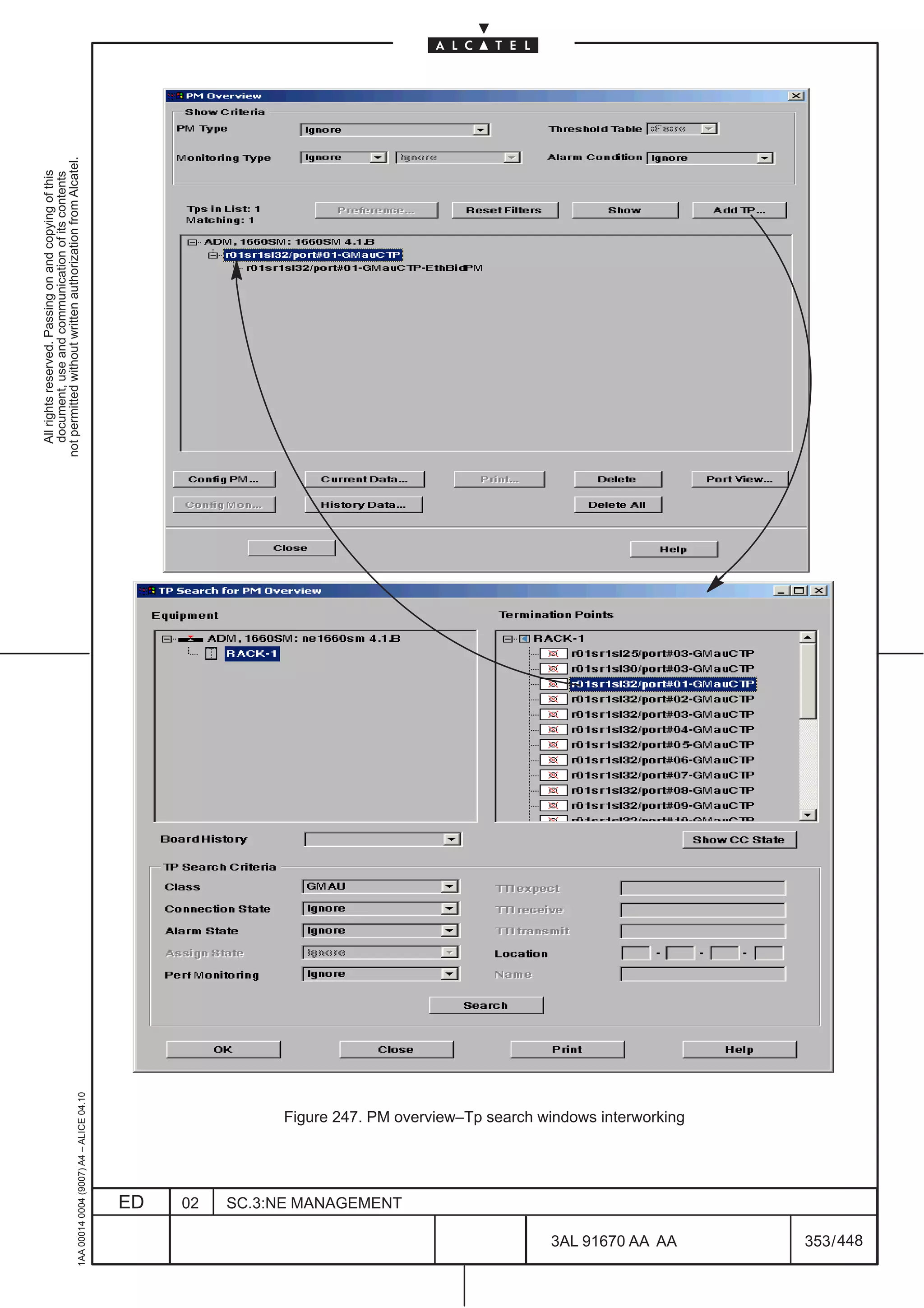
Figure 247. represents the interworking between these two dialogs.
The button area contains the following button (refer to Figure 246. ):
[1] ADD TP: it starts the search operations using the TP Search dialog. Only TP references are moved
by TP search into PMO dialog. This is a precondition to start PM/Monitoring search operations, using
TP selected by TP search as search roots.
1AA 00014 0004 (9007) A4 – ALICE 04.10
[2] Show: it starts the search for PM/Monitoring objects in the MIB. according to the filtering criteria.
[3] Reset Filter : it reset all filtering settings to default conditions.
ED 02 SC.3:NE MANAGEMENT
3AL 91670 AA AA 351 / 448
448](https://image.slidesharecdn.com/1660smoperr4-452b-100224044515-phpapp01/75/1660-S-M-Oper-R4-399-2048.jpg)
![[4] Preferences : it start the user preferences dialog. It is greyed out in USM not supporting this feature.
[5] Config PM : it starts the dialog for Current Data create/delete.
not permitted without written authorization from Alcatel.
[6] Config Mon : it starts the dialog for monitoring object create/delete.
All rights reserved. Passing on and copying of this
document, use and communication of its contents
[7] Current Data: it starts the dialog for PM counter visualization
[8] History Data: it starts the dialog for PM counter visualization
[9] Print: it starts a request to print the tree content
[10] Delete: it starts a request to remove the selected objects (monitoring and/or).
[11] Delete All: it destroys the TP list and make empty the TreeGadget
[12] Port View: it starts the Port View . PMO dialog is not closed after Port View or Port details dialog
opening.
1AA 00014 0004 (9007) A4 – ALICE 04.10
ED 02 SC.3:NE MANAGEMENT
3AL 91670 AA AA 352 / 448
448](https://image.slidesharecdn.com/1660smoperr4-452b-100224044515-phpapp01/75/1660-S-M-Oper-R4-400-2048.jpg)


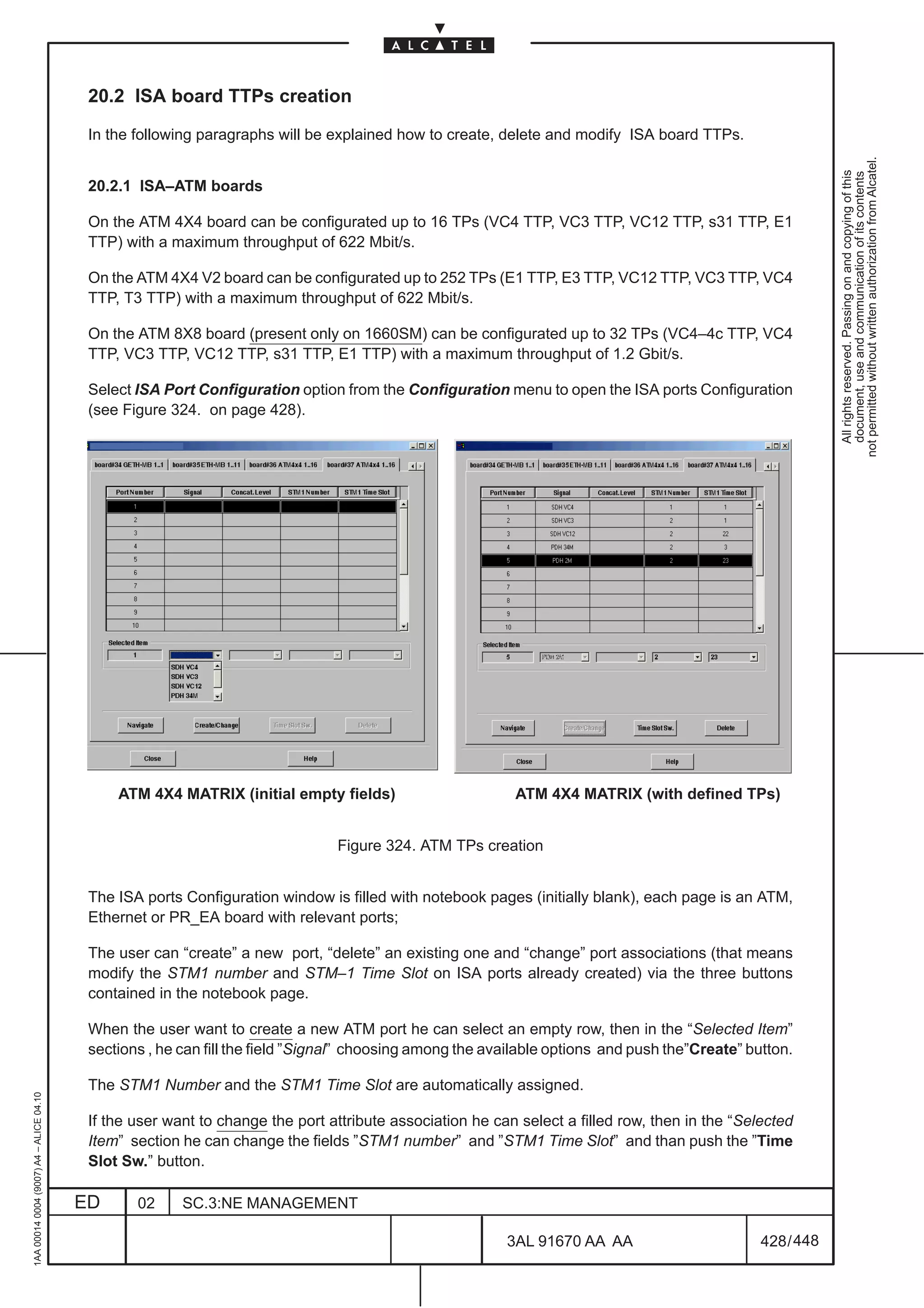
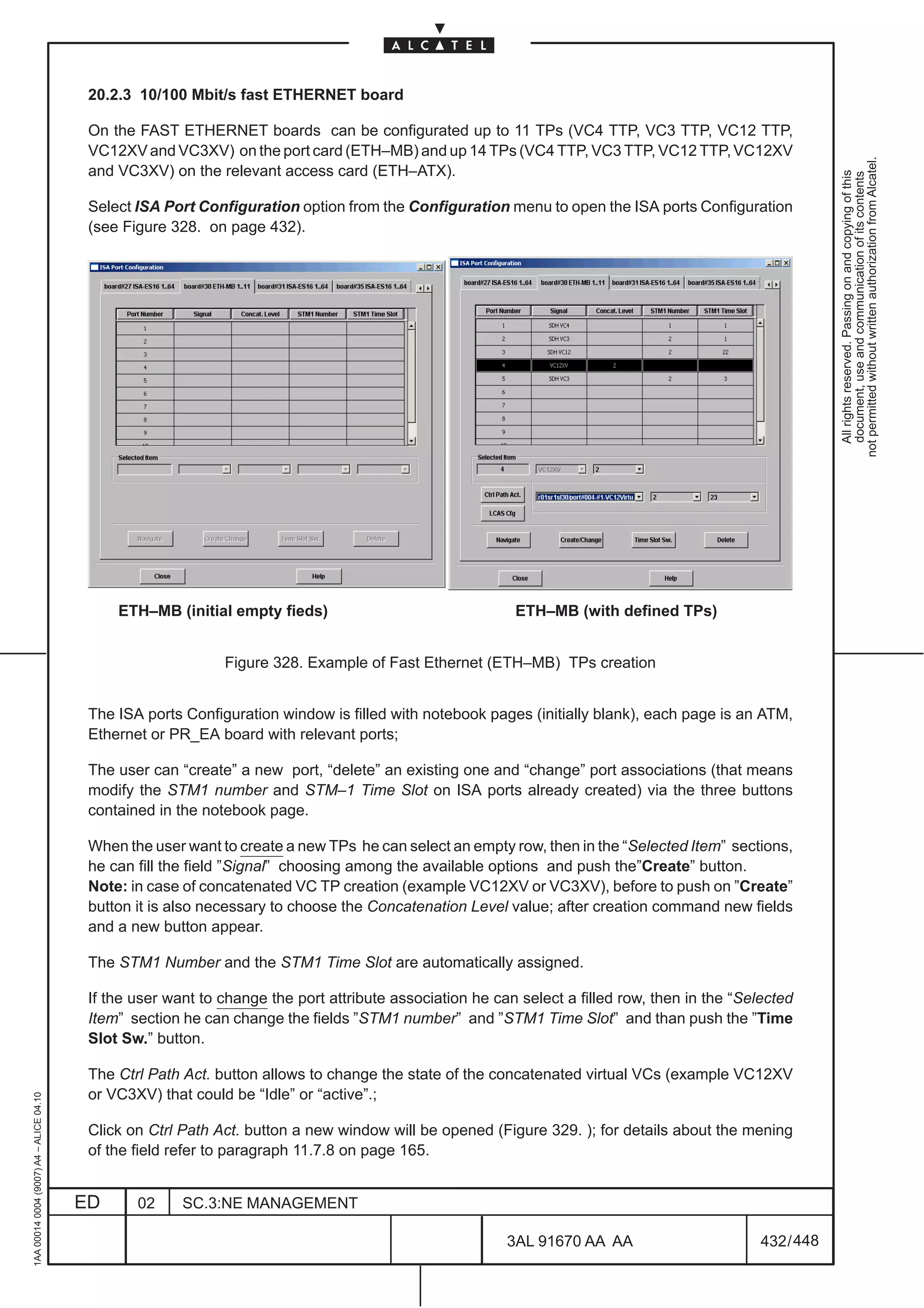
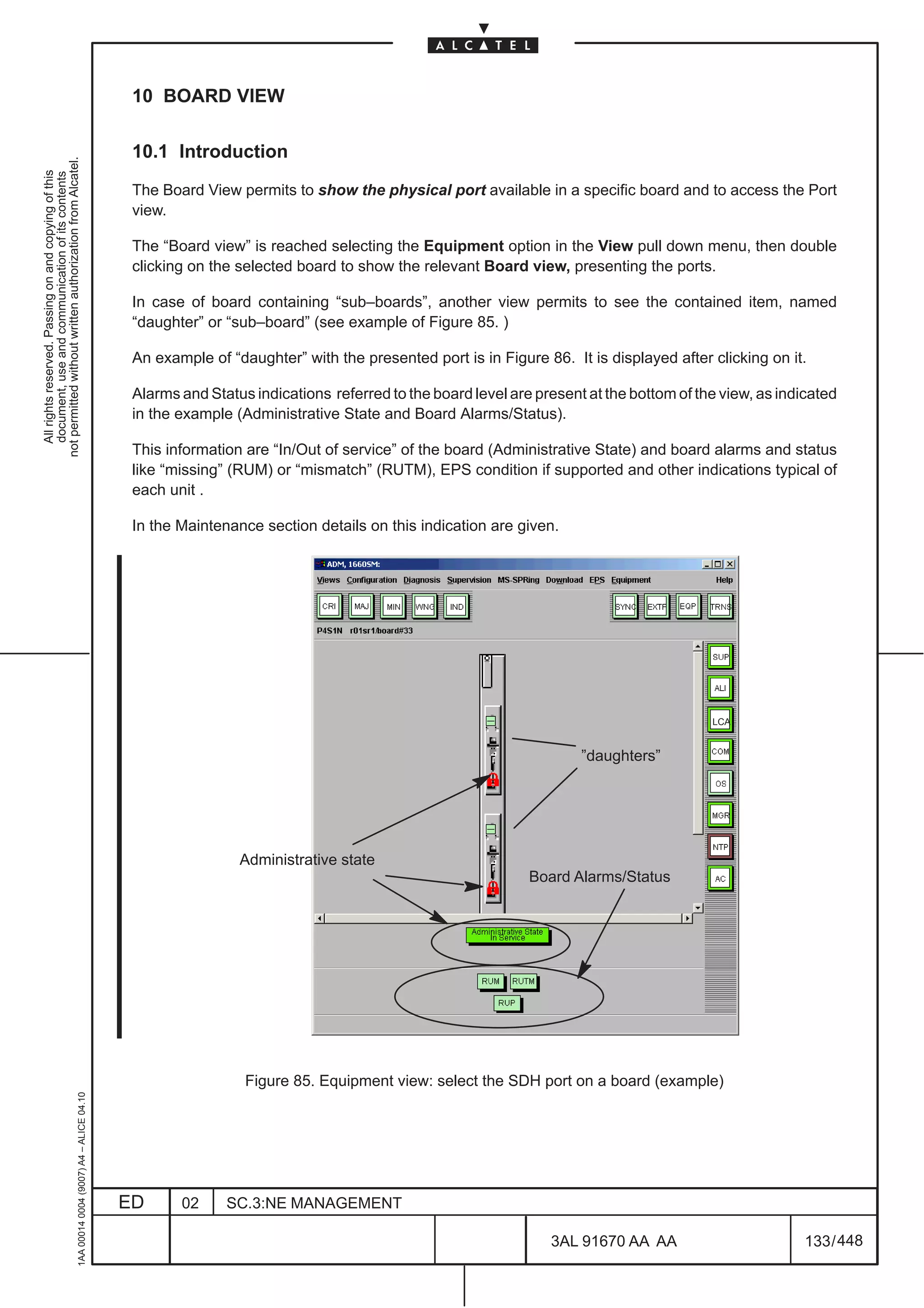
![20.2.4 Gigabit/s ETHERNET board
Two architectures are possible to provide Gigabit Ethernet ports:
not permitted without written authorization from Alcatel.
[1] 10/100Mbit/s Ethernet board (ETH–MB)+GBIT Access (GETH–AG); this feature is supported only
All rights reserved. Passing on and copying of this
document, use and communication of its contents
on 1650SMC and 1660SM.
With this architecture can be configurated up to 2 TPs (VC4XV TTP Type concatenation level=1) on
the GETH–AG access card and up to 11 TPs (VC4 TTP, VC3 TTP, VC12 TTP, s31 TTP, E1 TTP Type)
on the ETH–MB main board taking into account that the maximum throughput must not exceed 622
Mbit/s.
[2] GIGABIT board (GETHMB) stand–alone; this feature is supported on all OMSN (1640FOX,
1650SMC and 1660SM).
With this architecture can be configurated up to 4 TPs (VC4XV Type) on each board taking into
account that the maximum throughput must not exceed 622 Mbit/s in 1640FOX and 1650SMC (for
example it is possible to configure 1 port VC4XV with a max. concatenation level equal to 4 or as
alternative 4 ports VC4XV with concatenation level equal to 1).
The same rule above described are applicable to 1660SM when the GIGABIT board (GETHMB)
is equipped in normal slot (i.e. slot with a throughput of 622 Mbit/s).
In 1660SM are also available slot called “enhanced” (25, 26,28,29,34,35,37,38) where the
throughput per board is 1.2 Gbit/s.
If the GIGABIT board (GETHMB) is equipped in one of these slot it is possible to reach a max.
concatenation level equal to 7 per port ; of course this means that there is only one VC4XV with
concatenation level =1 available for another port and no resources for the last two ports present on
the board.
For more details read the Gigabit Ethernet description reported in the Technical Handbook.
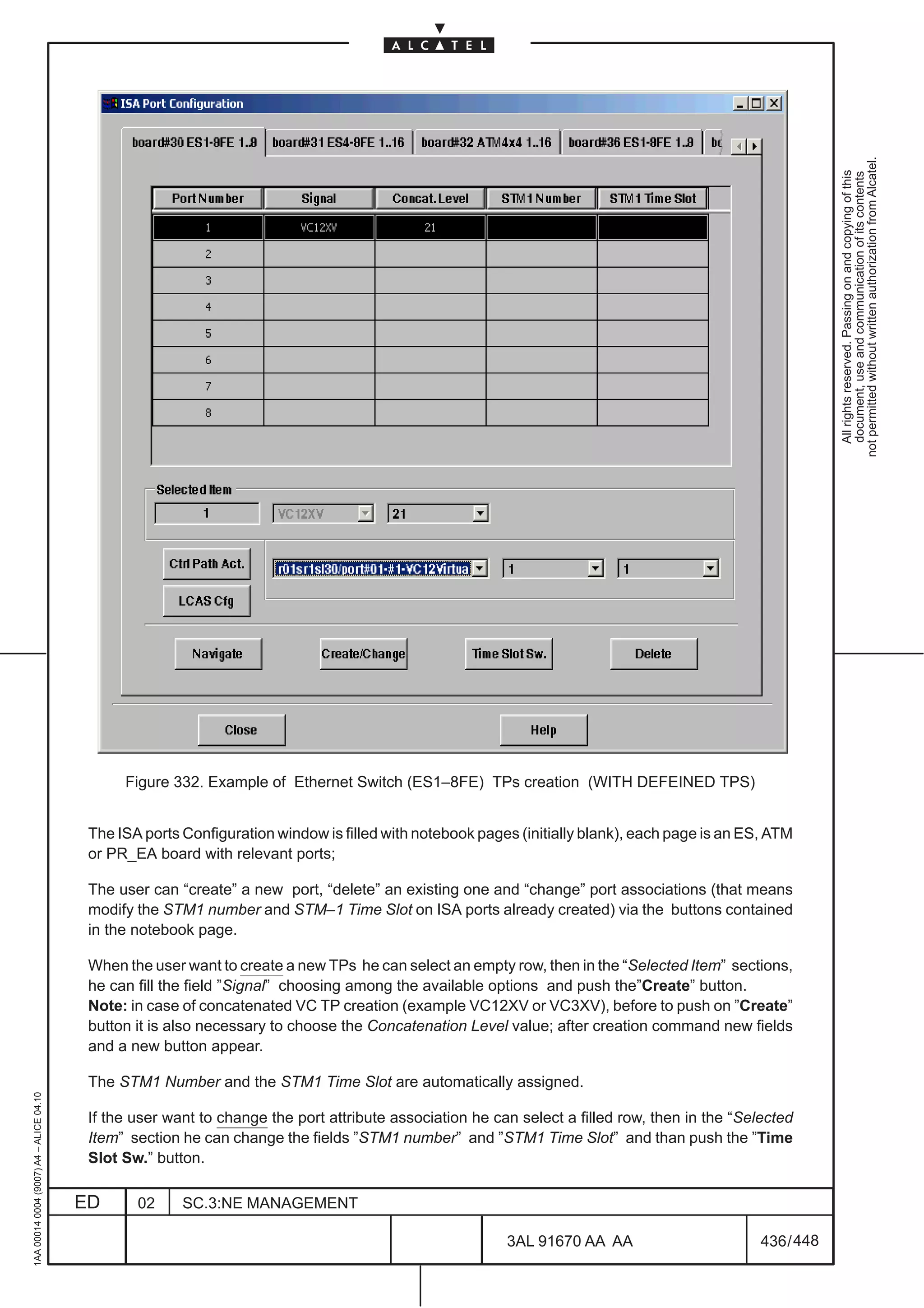
The Gigabit Ethernet TPs creation follows the same rules described for the 10/100Mbit/s Ethernet Board;
refer to paragraph 20.2.3.
1AA 00014 0004 (9007) A4 – ALICE 04.10
ED 02 SC.3:NE MANAGEMENT
3AL 91670 AA AA 434 / 448
448](https://image.slidesharecdn.com/1660smoperr4-452b-100224044515-phpapp01/75/1660-S-M-Oper-R4-482-2048.jpg)
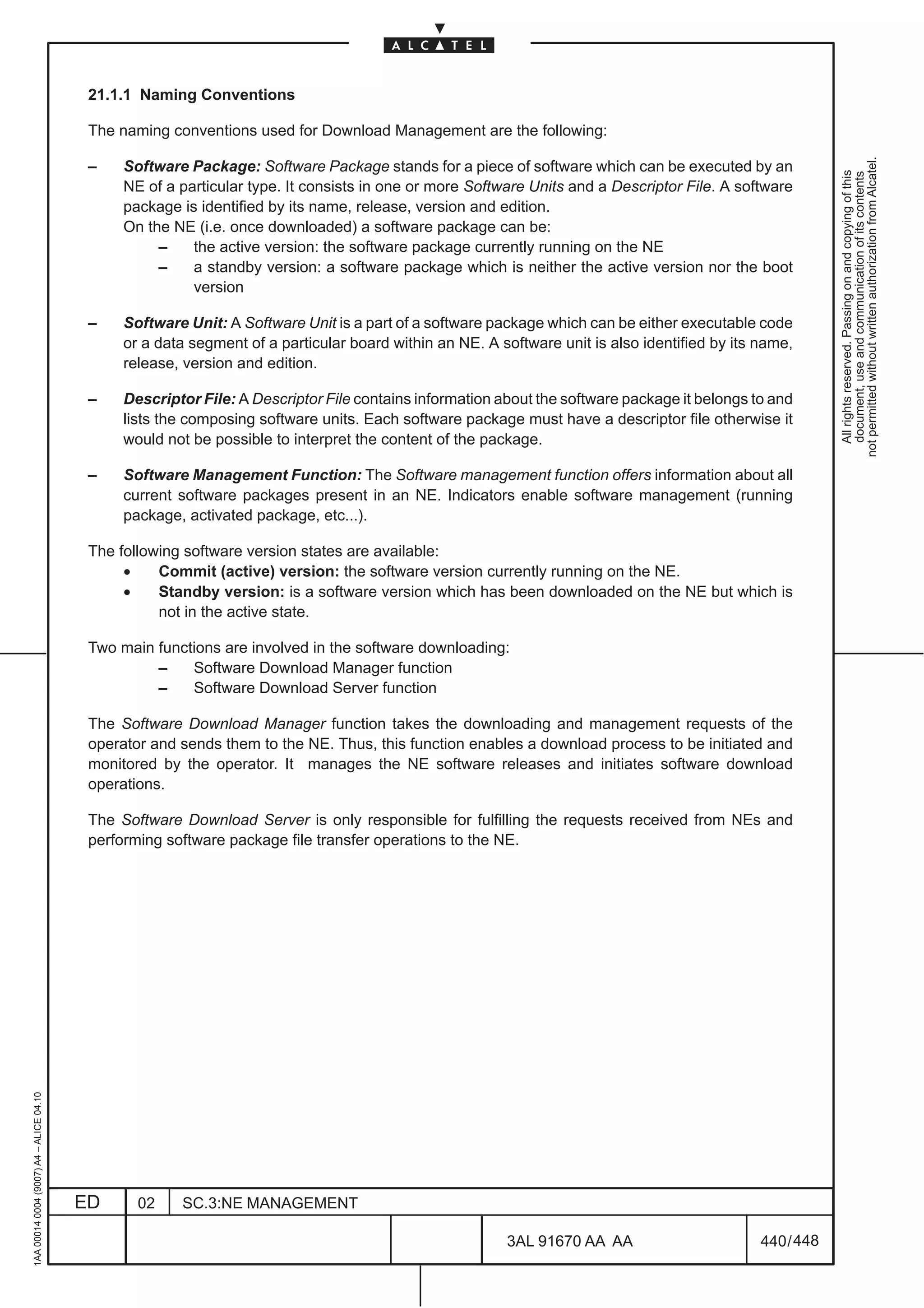
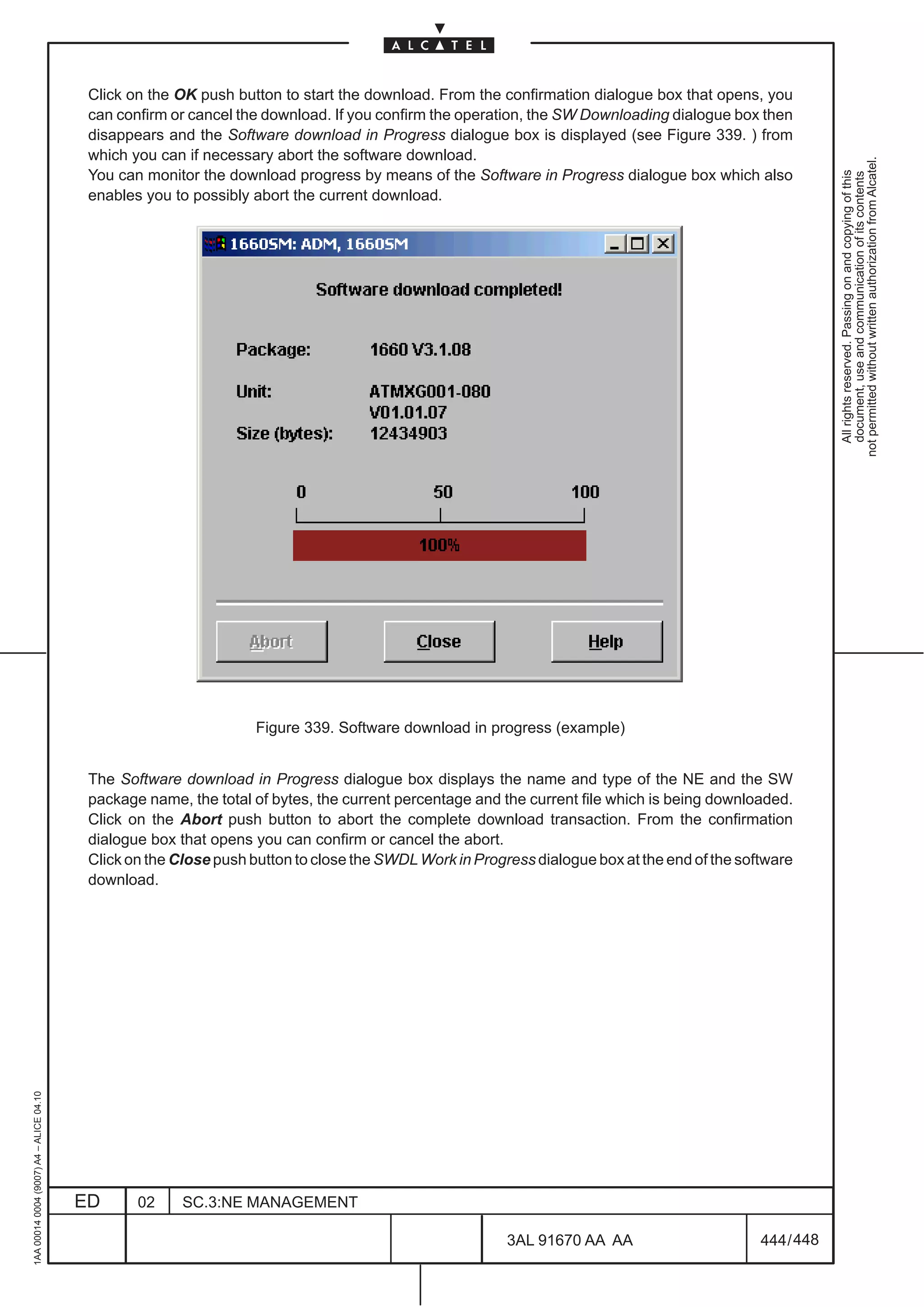
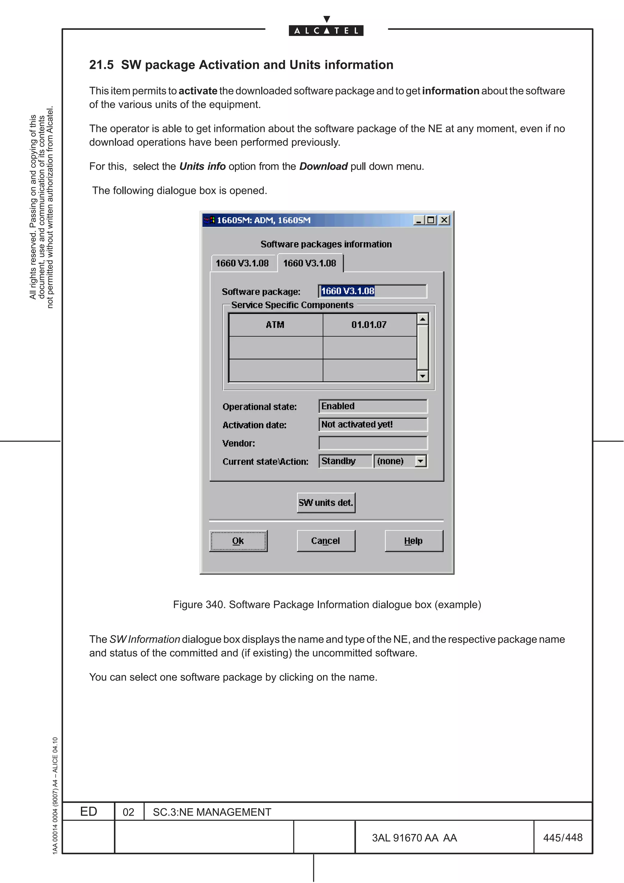
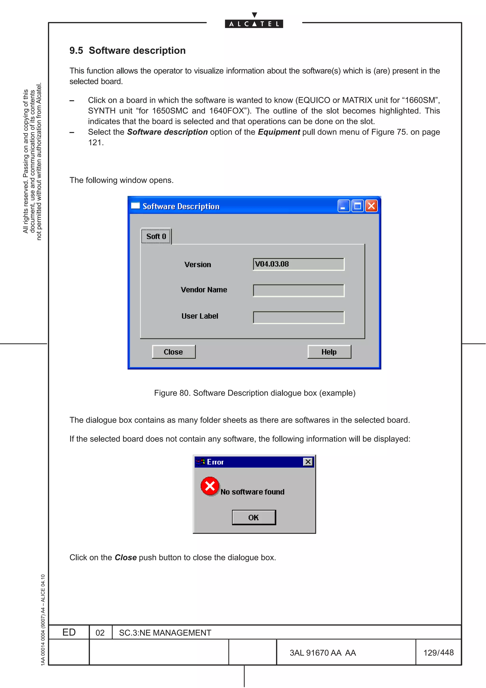
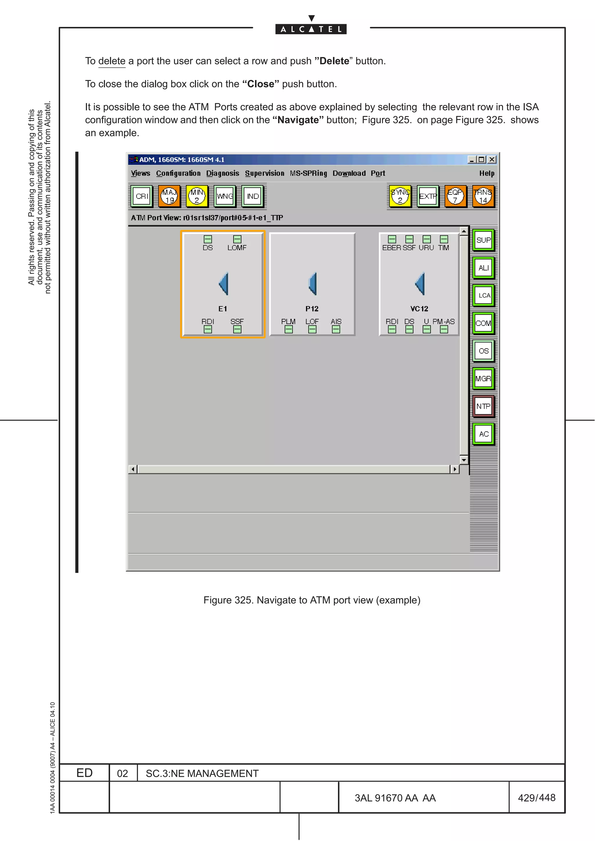
![The following fields are displayed:
– Software package: name, release, version, edition of the package,
– Service Specific Components: name, release, version, edition of the Service Specific Components
not permitted without written authorization from Alcatel.
(example ATM, IP etc.)
All rights reserved. Passing on and copying of this
document, use and communication of its contents
– Operational state: enabled or disabled,
– Activation date: date and hour of the last activation
– Vendor: the supplier of the product,
– Current stateAction: commit or stand–by and with the option button; none/Force/Activate/Delete
current state = standby means the package is not active on the NE
current state = commit means the package is active on the NE
action = (none) means no action to do
action = activate serves to activate the selected SW package
action = force
Select the Activate option of the “CurrentStateAction” field, to activate the Software package
The Sw units Det. button allows to give more information about a selected software package.
Clicking on it, the following window is displayed:
Figure 341. Detail software package (example)
Clicking on [–] symbol behind each software package all details disappear.
When you click on Close the previous view is displayed (Figure 340. ).
In Figure 340. when you click on the:
– OK push button you close dialogue box,
– Cancel push button you close the SW Information dialogue box,
1AA 00014 0004 (9007) A4 – ALICE 04.10
– Help push button you access to help on context.
ED 02 SC.3:NE MANAGEMENT
3AL 91670 AA AA 446 / 448
448](https://image.slidesharecdn.com/1660smoperr4-452b-100224044515-phpapp01/75/1660-S-M-Oper-R4-494-2048.jpg)
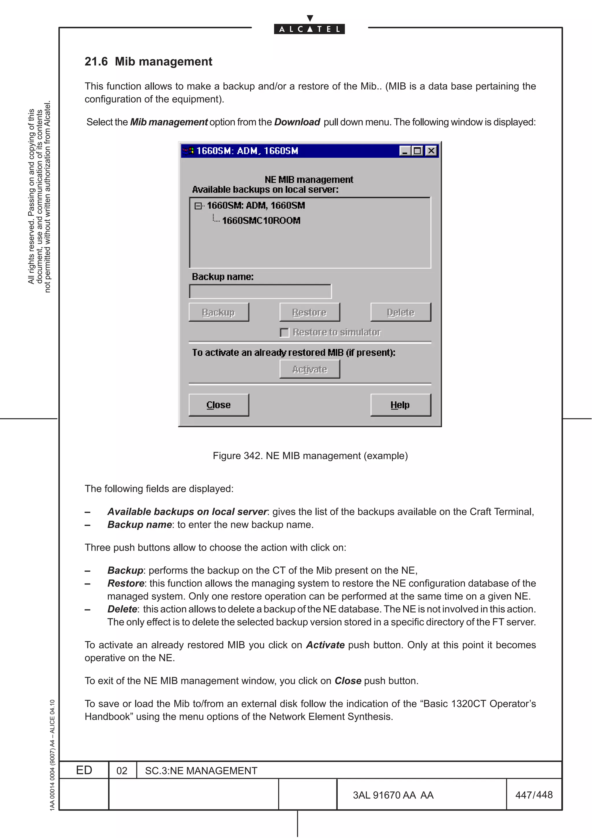


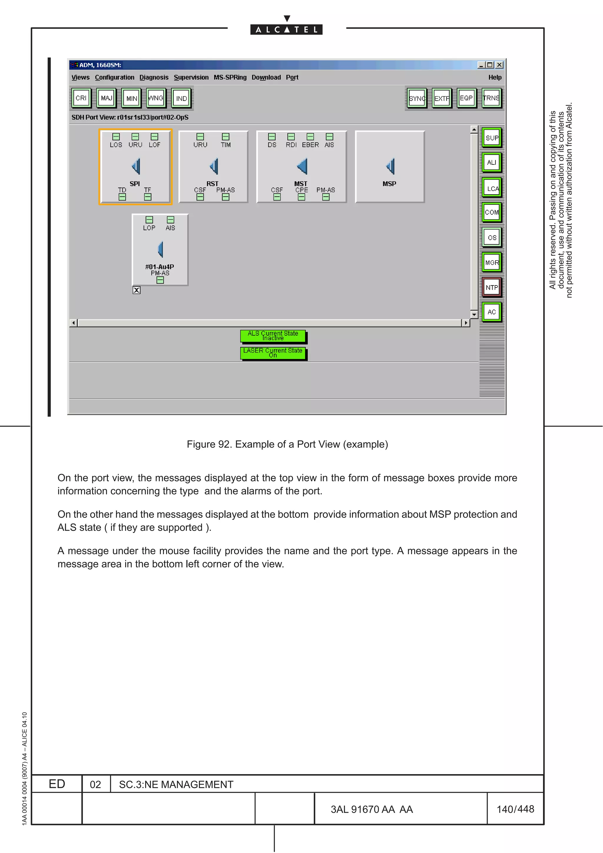
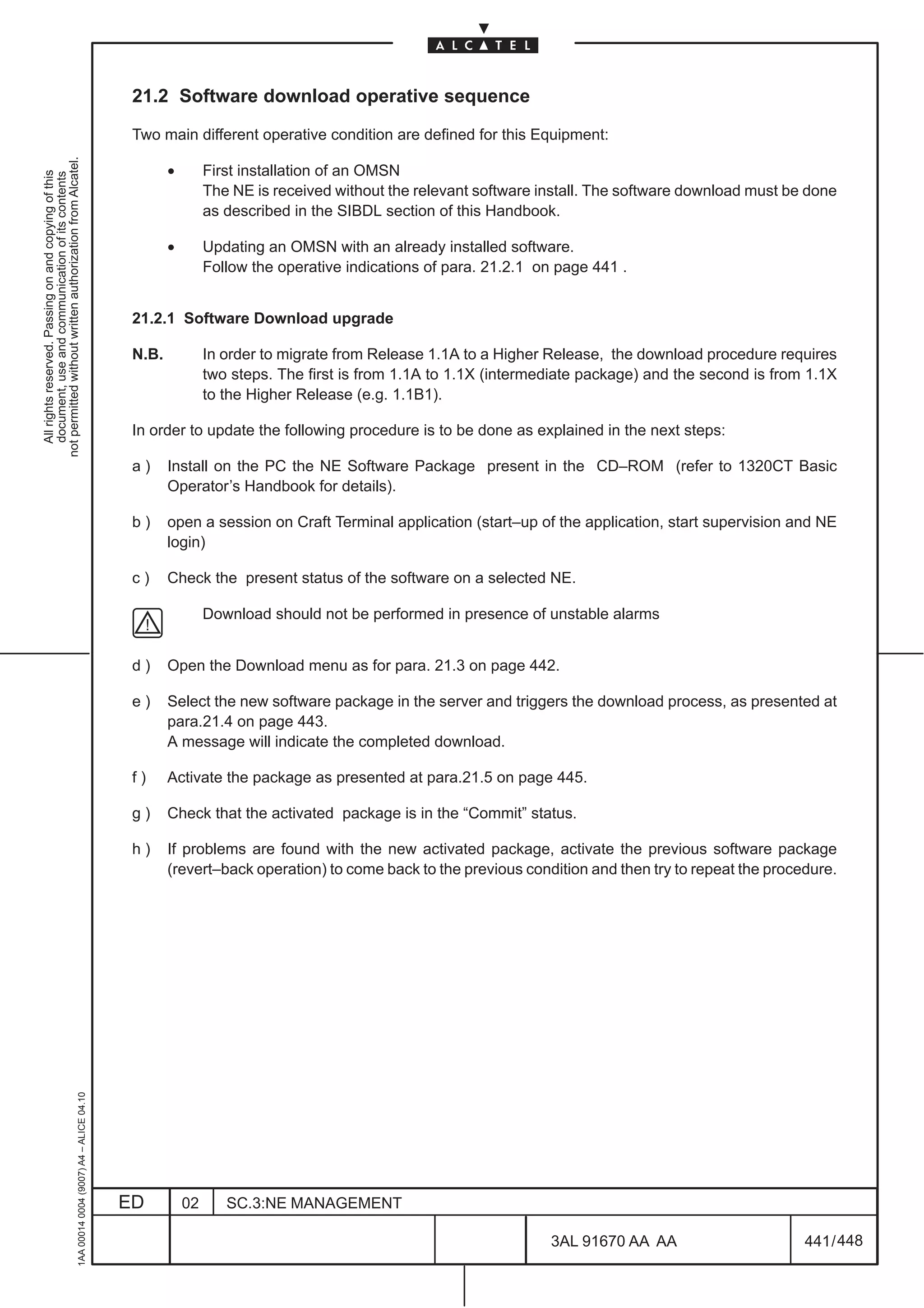
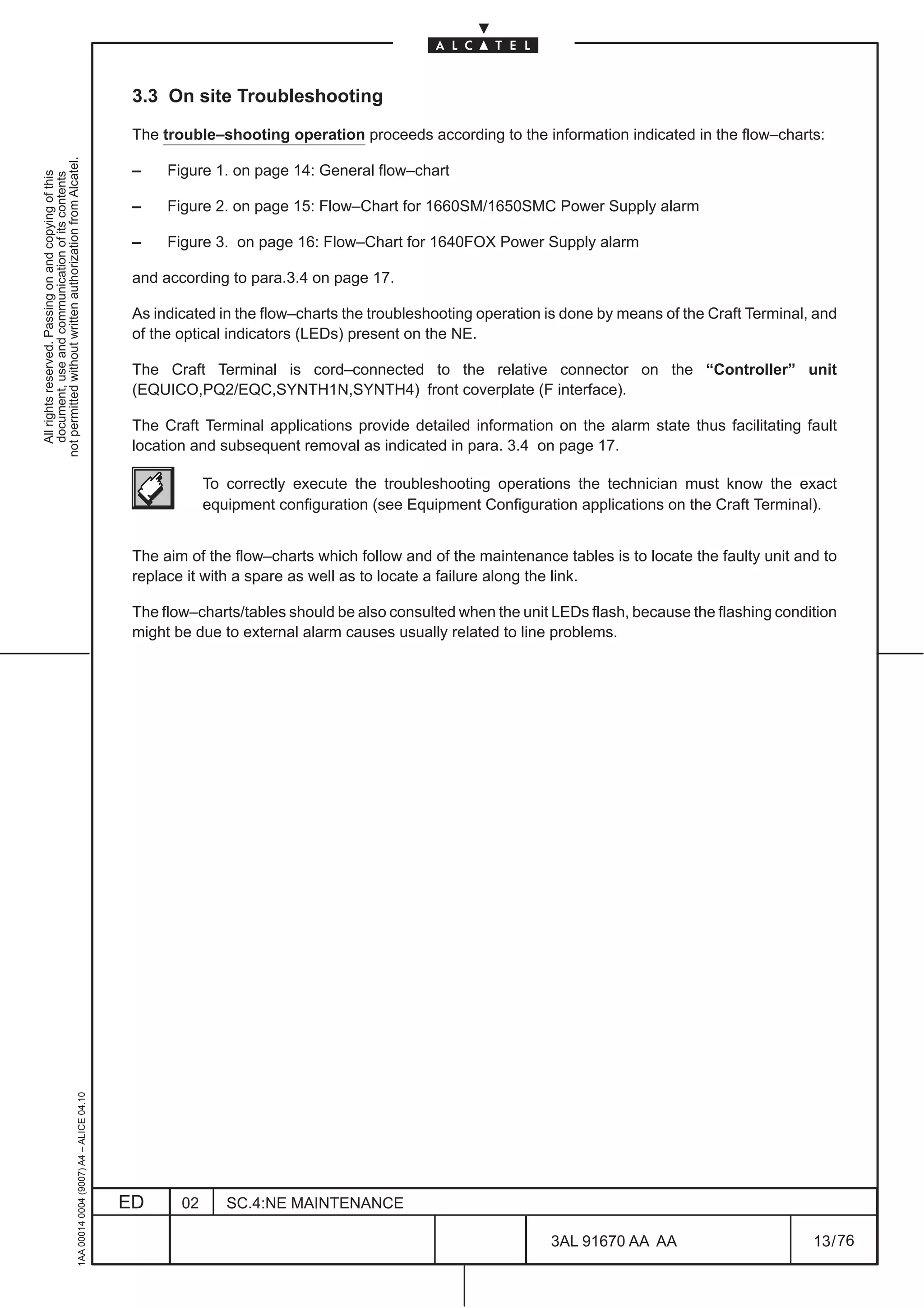
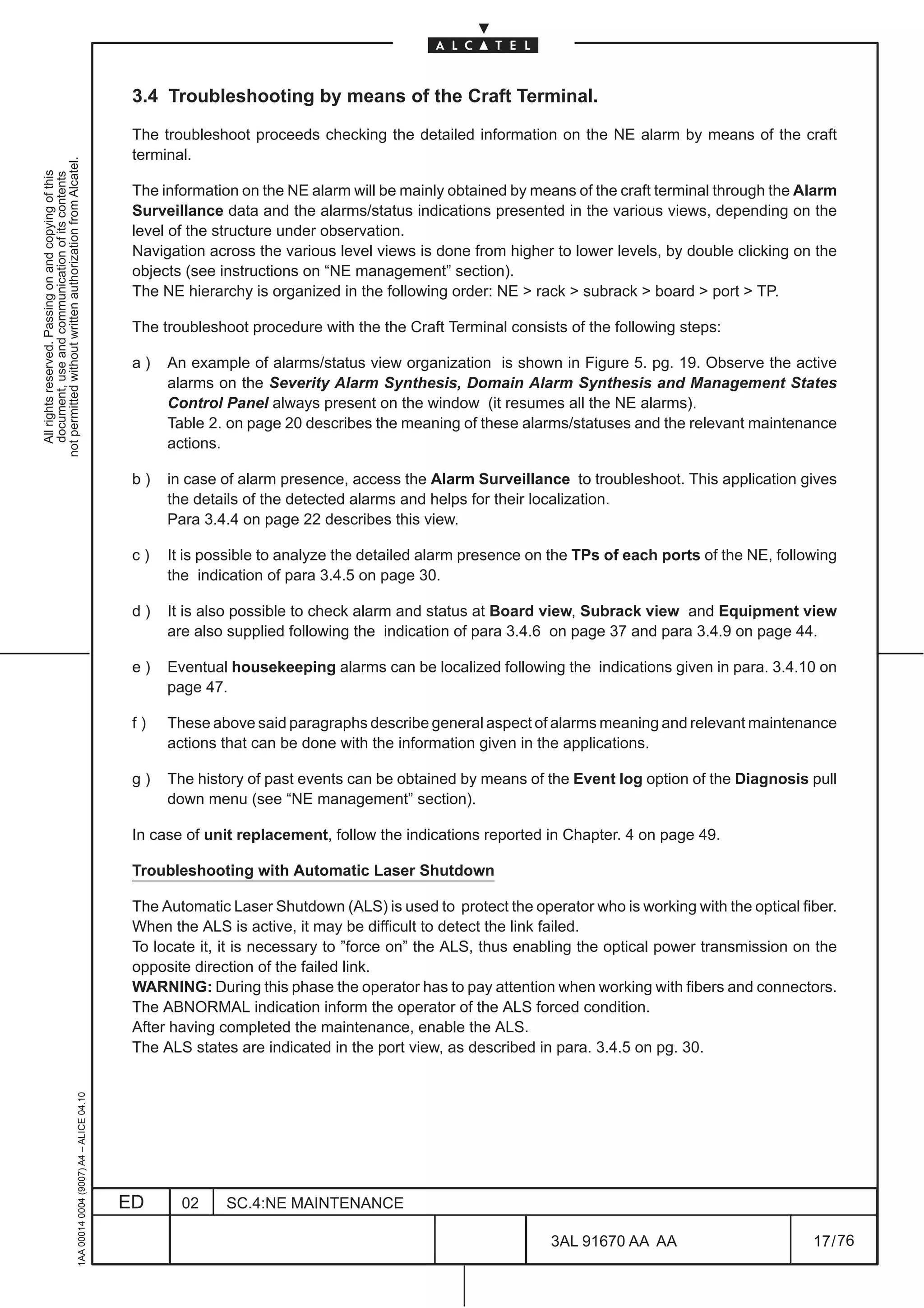
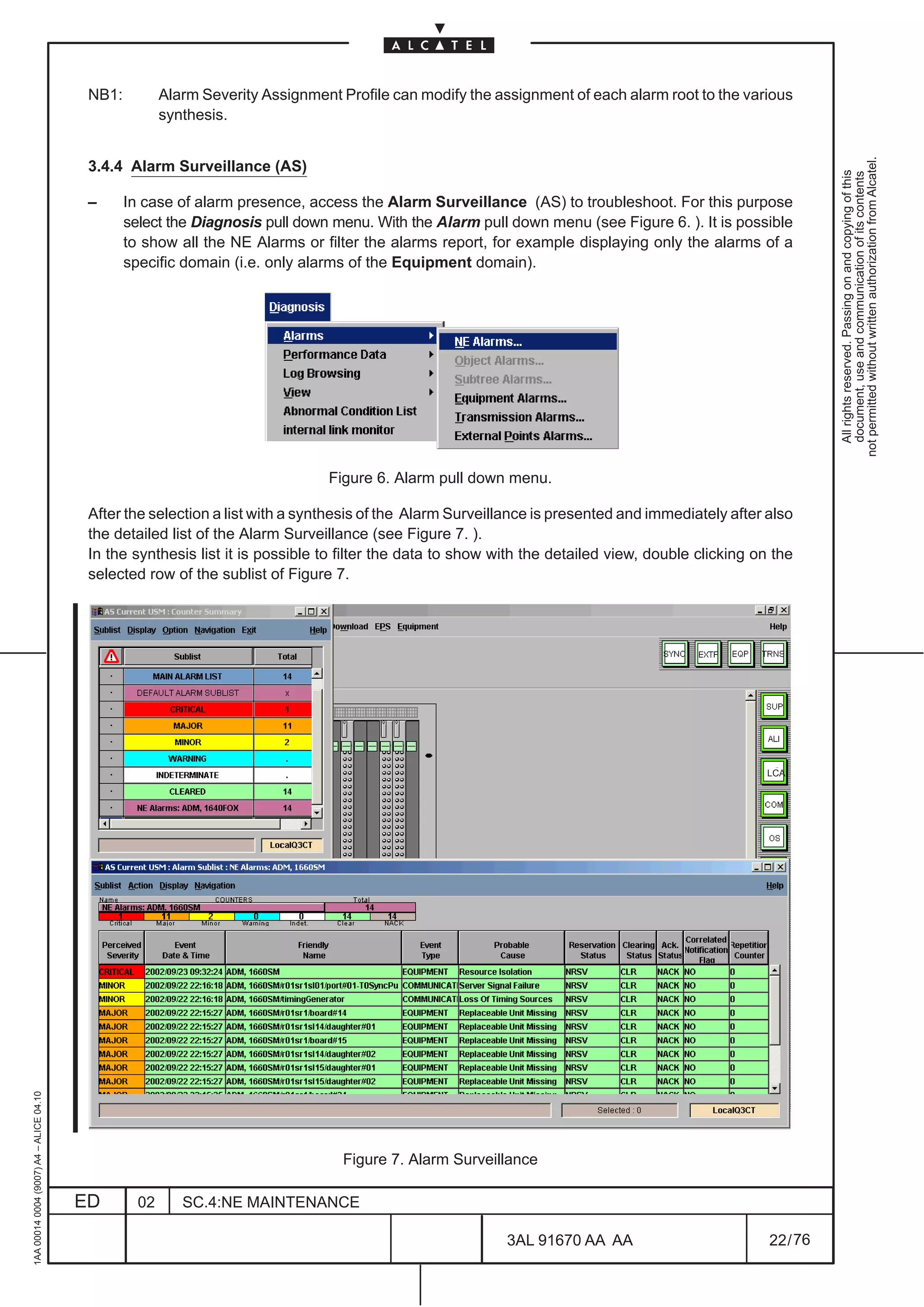
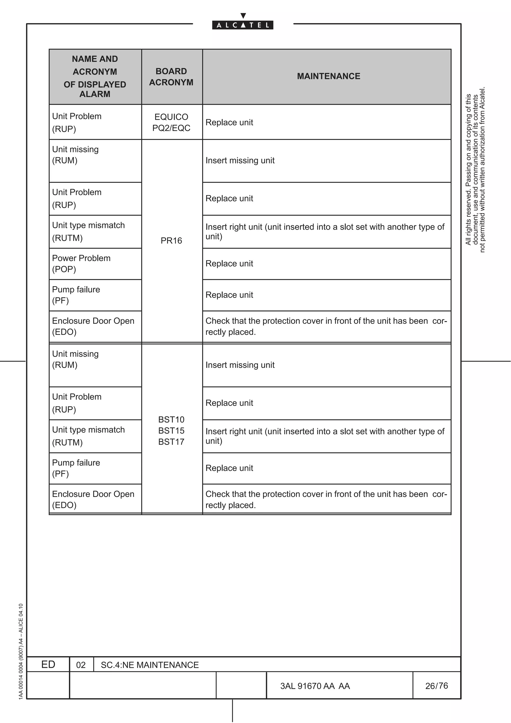
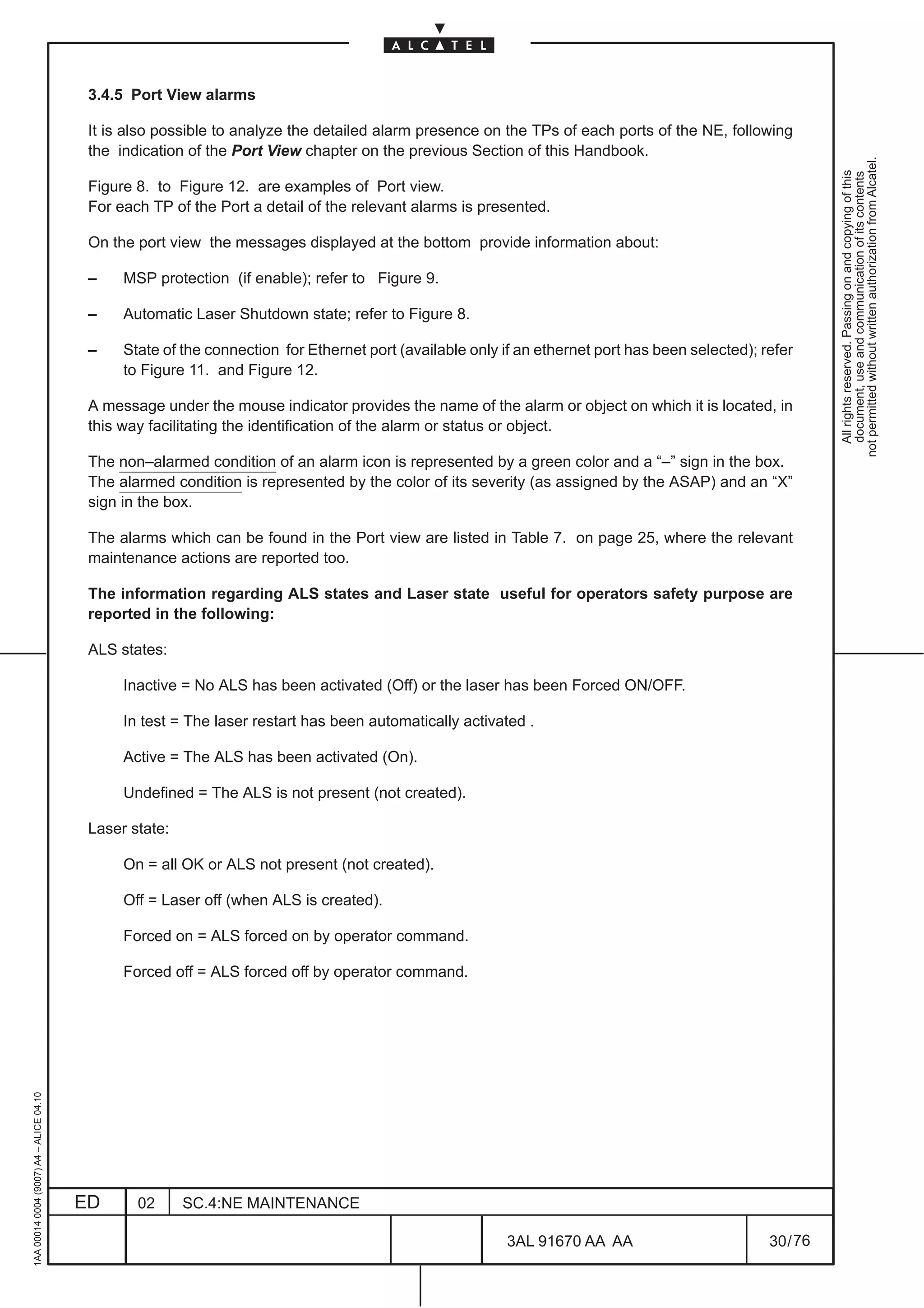
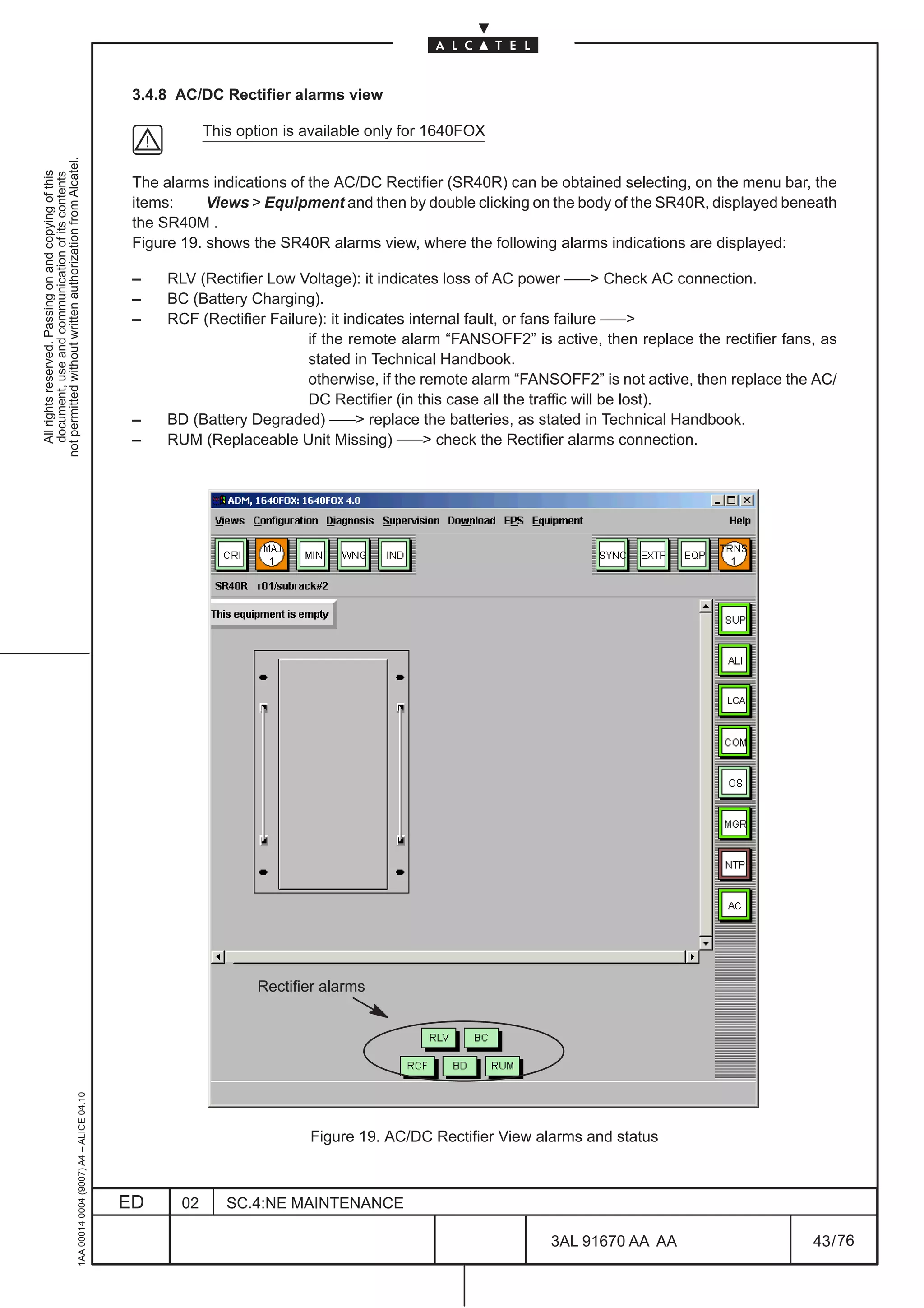
![3 CORRECTIVE MAINTENANCE (TROUBLESHOOTING)
3.1 Purpose of the procedure
not permitted without written authorization from Alcatel.
All rights reserved. Passing on and copying of this
document, use and communication of its contents
Troubleshooting involves the detection, location and correction of failures in the equipment and the
replacement of the defective parts.
3.2 Troubleshooting organization
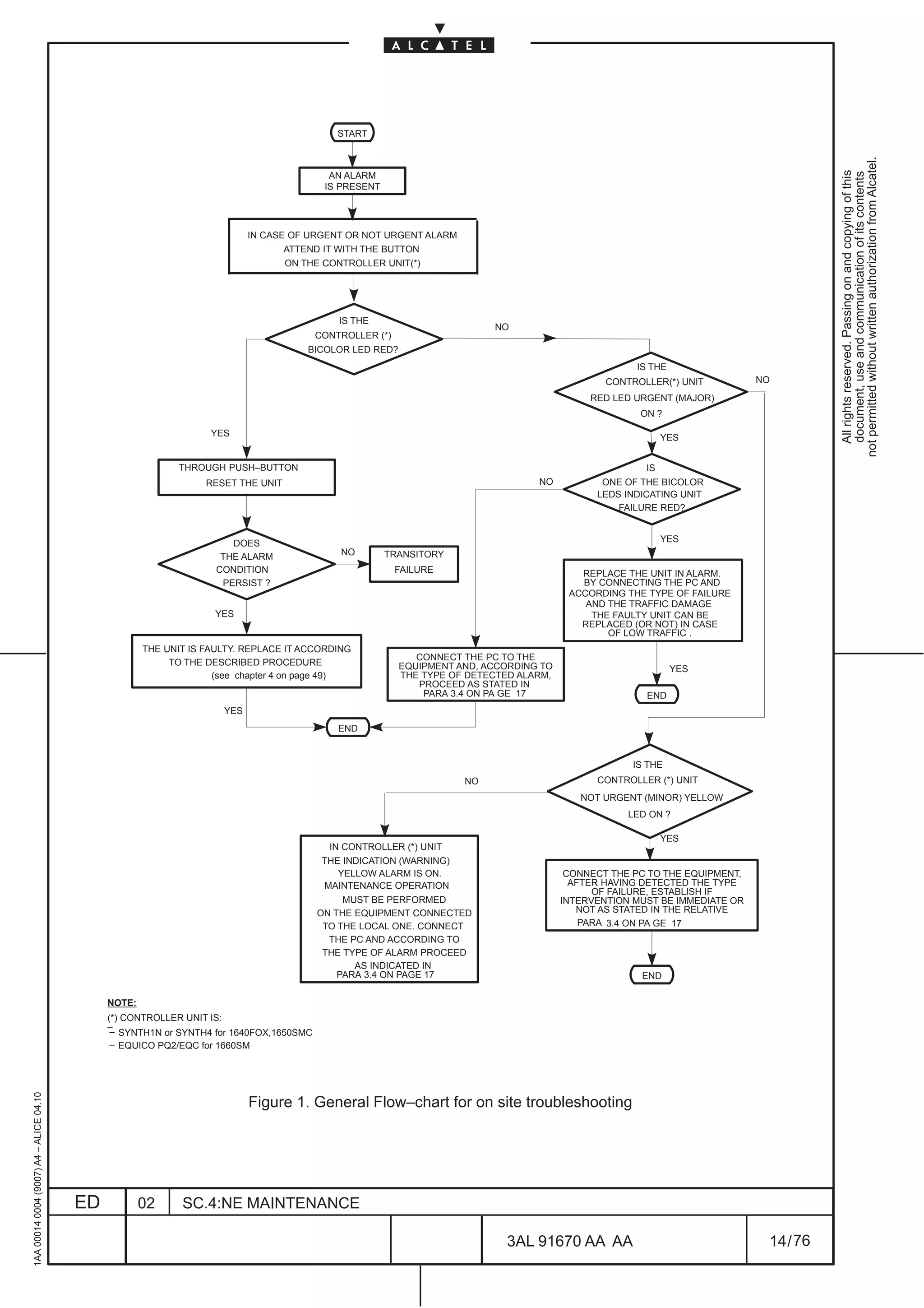
The troubleshooting procedure is carried out with the help of some flow–charts and tables, reported
hereinafter. Anyway this method does not deal with the following aspects (which are to be deduced in other
ways):
– faulty electronic alarm indication, processing and detection circuits
– faulty wiring (back–panel, connectors, etc.)
The following interfaces are present to troubleshoot the equipment :
• Q3 interface for Telecommunication Management Network
• Q–ECC interface for Telecommunication Management Network (via DCC channels, linked to
the relevant OS)
• F interface for Craft Terminal (Local or Remote)
• Remote Alarm for Supervisory Center
• LEDs on the units of the NE
Usually maintenance is firstly done via software (TMN or Remote Craft Terminal) to locate the faulty
equipment and the faulty unit or the faulty path and then on site to physically solve the trouble.
The Maintenance can be done :
[1] from a TMN network management center
[2] from a Remote Craft Terminal (RCT) management center
[3] from a station supervisory center
[4] on site
[1] TMN network management center: by means of the TMN the maintenance technician can see the
alarms sent by each equipment of the managed network (see the relevant TMN handbooks).
[2] Remote craft terminal: the operator, connected to a local NE , can remotely manage and
troubleshooting a network composed of max 32 NEs included itself. This handbook is used.
1AA 00014 0004 (9007) A4 – ALICE 04.10
ED 02 SC.4:NE MAINTENANCE
3AL 91670 AA AA 9 / 76
76](https://image.slidesharecdn.com/1660smoperr4-452b-100224044515-phpapp01/75/1660-S-M-Oper-R4-505-2048.jpg)
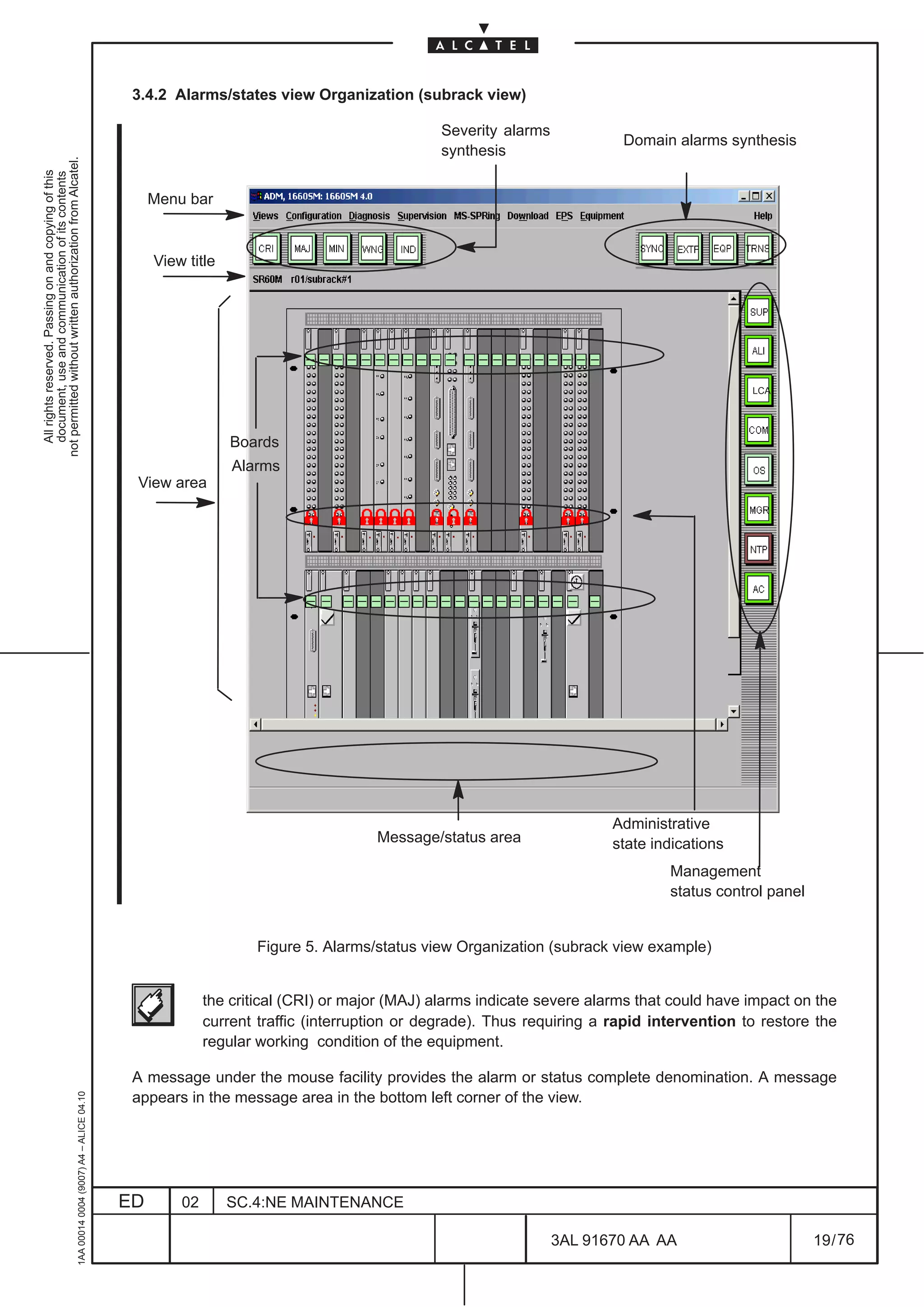
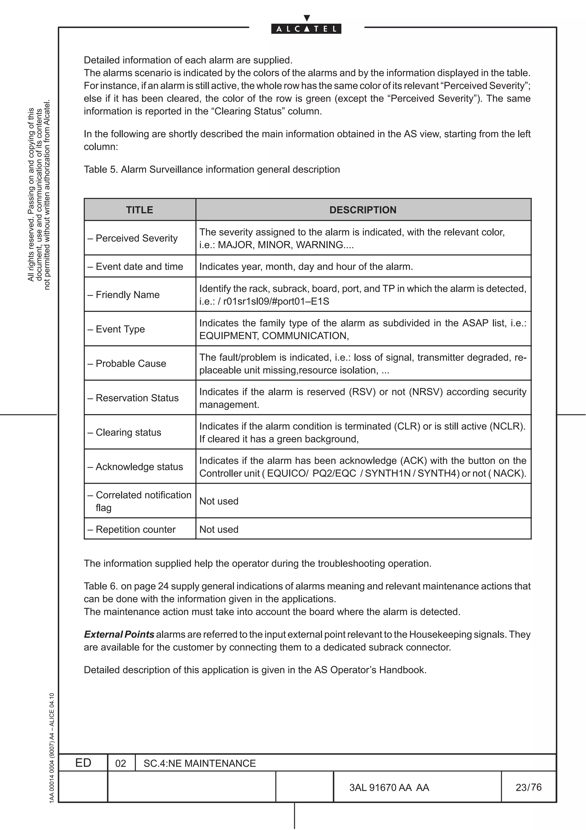
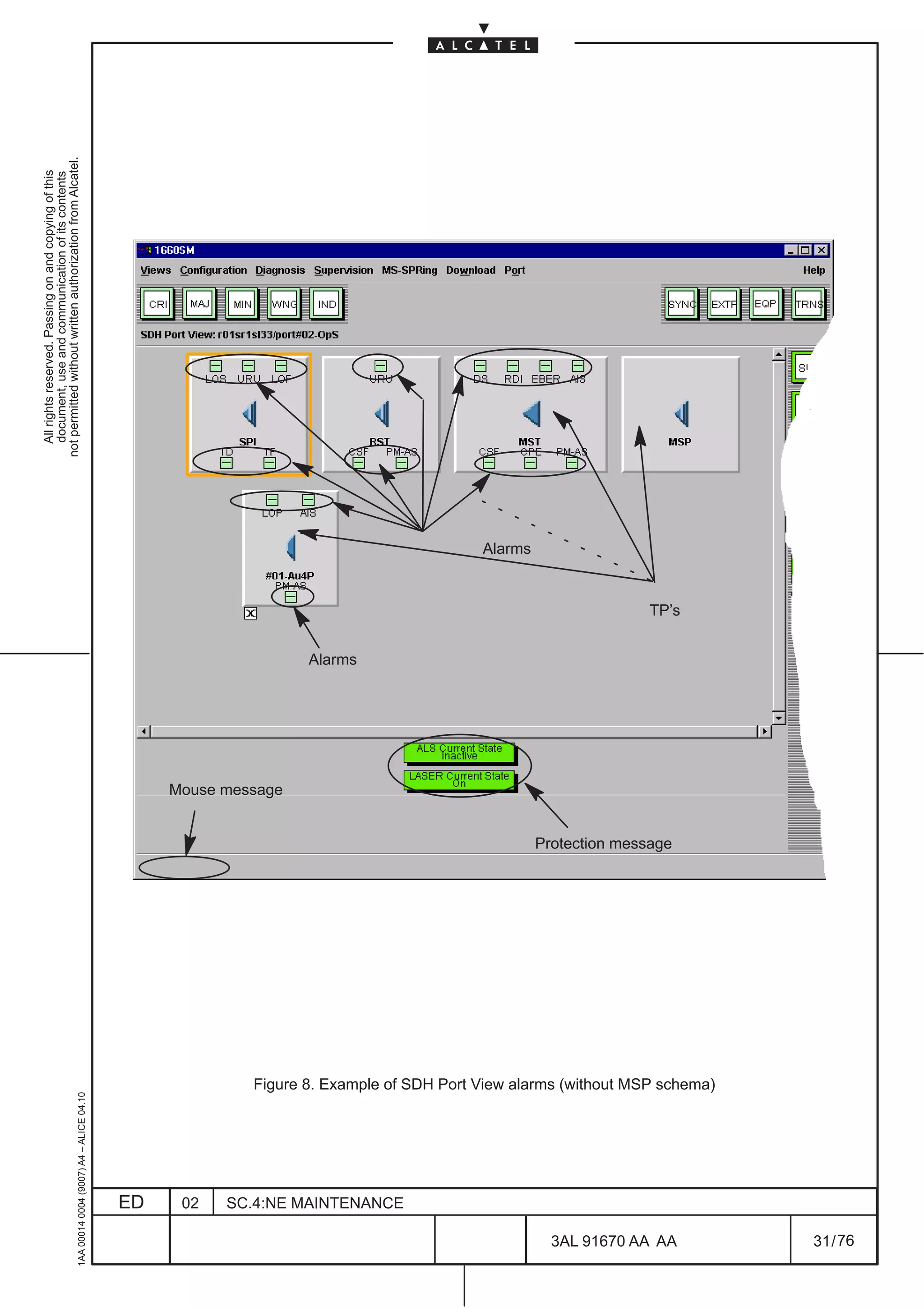
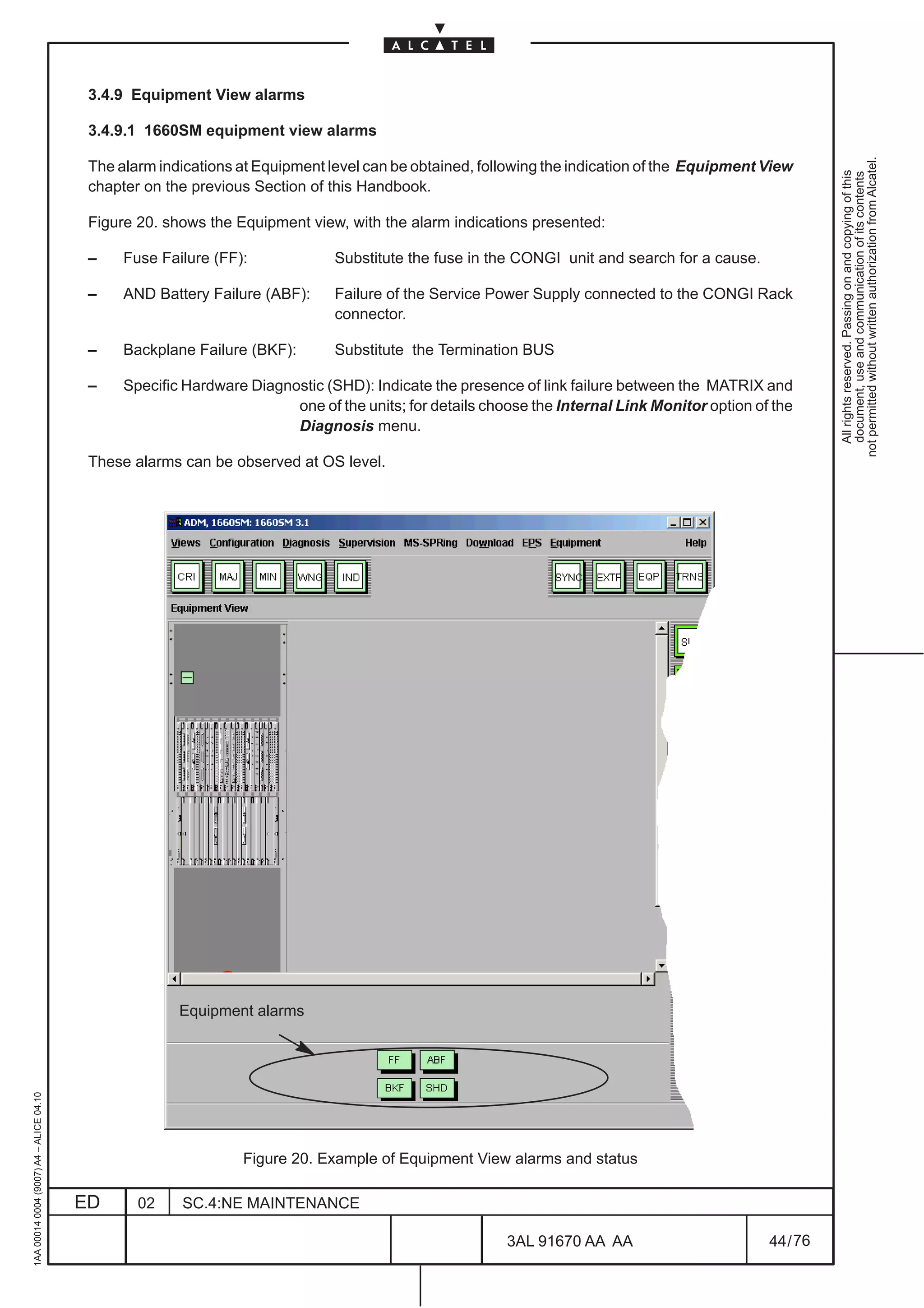
![[3] Station supervisory center: the maintenance technician refers to the Remote Alarms received from
the equipment in a centralized office of the station i.e. :
• 1660SM and 1650SMC
not permitted without written authorization from Alcatel.
All rights reserved. Passing on and copying of this
document, use and communication of its contents
– T URGENT (MAJOR and CRITICAL), T NOT URGENT (MINOR): remote alarms pertaining to
the urgent, not urgent alarm type.
– TOR, TAND: remote alarms respectively due to the decrease or loss of one or both station
power supply DC voltages.
– INT: Remote alarm pertaining to the local (internal) alarm type
When a second CONGI unit is used the following remote alarms are added:
– TORC, TANC: remote alarms respectively due to the loss of +3,3V generated by the on board
converter in of one or both the CONGI units.
– IND: Indeterminate alarm synthesis. Indicates synthesis of alarms not associated to others
severities. Not operative.
– TUP: remote alarm due to microprocessor fault in the EQUICO unit (for 1660SM), PQ2/EQC
unit (for 1660SM Rel. 5.1) or SYNTH1N/SYNTH4 unit (for 1640FOX,1650SMC)
– LOSQ2: remote alarm due to loss of communication with Mediation Device. Not operative.
• 1640FOX
– T URGENT (MAJOR and CRITICAL), T NOT URGENT (MINOR): remote alarms pertaining to
the urgent, not urgent alarm type.
– INT (MAJOR or CRITICAL): Remote alarm pertaining to the local (internal) alarm type
– INTALM (WARNING): Remote alarm due to alarm detection from the external Converter
SR40R.
– TAND (MAJOR or CRITICAL): remote alarm due to the loss of power supply (battery–fail or
–3.3VService fail).
– FANSOFF1 (WARNING): remote alarm due to failure of FOX fans.
– FANSOFF2 (WARNING): remote alarm due to failure of external Converter (SR40R) fans.
Depending on the supervisory center organization, it is possible to locate the equipment in troubles and
to detect the failure type and source.
[4] On site : the operator is on site in case :
1) the equipment is not managed by a TMN or by a Remote Craft terminal (RCT)
2) the equipment is not reachable by the remote manager (TMN or RCT) and is therefore isolated
3) link problems are present
4) the trouble has been located and a substitution is necessary
In case 1 ) , 2 ), 3 ), the alarmed equipment is checked by means of the local Craft Terminal and of rack
LED indications and station buzzers.
The NE is provided with LEDs which indicate:
1AA 00014 0004 (9007) A4 – ALICE 04.10
ED 02 SC.4:NE MAINTENANCE
3AL 91670 AA AA 10 / 76
76](https://image.slidesharecdn.com/1660smoperr4-452b-100224044515-phpapp01/75/1660-S-M-Oper-R4-506-2048.jpg)

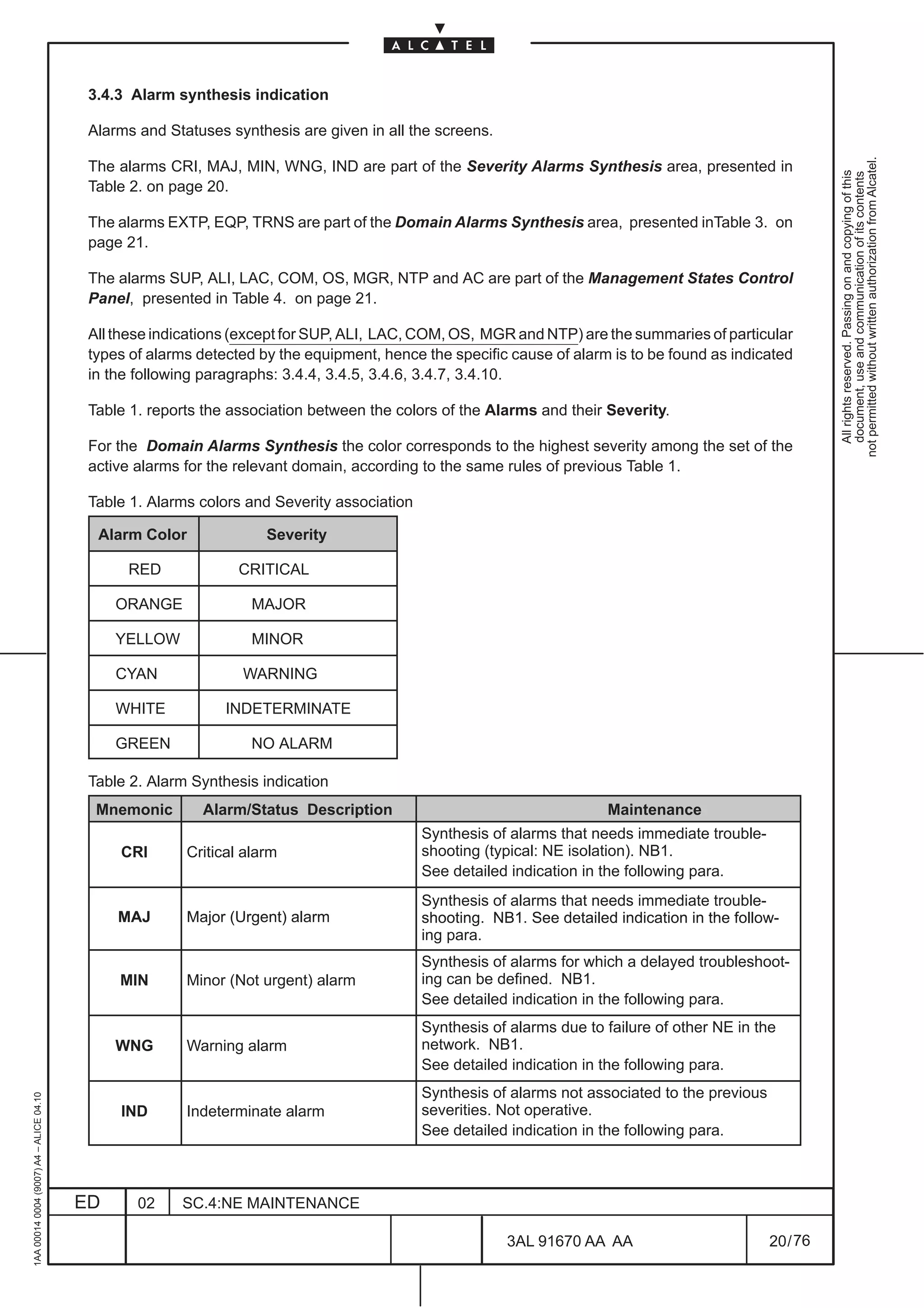
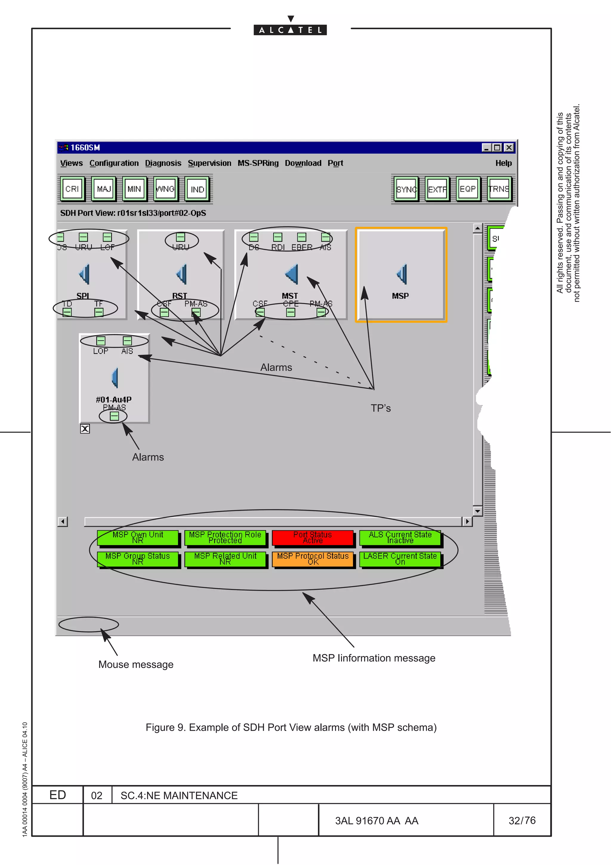

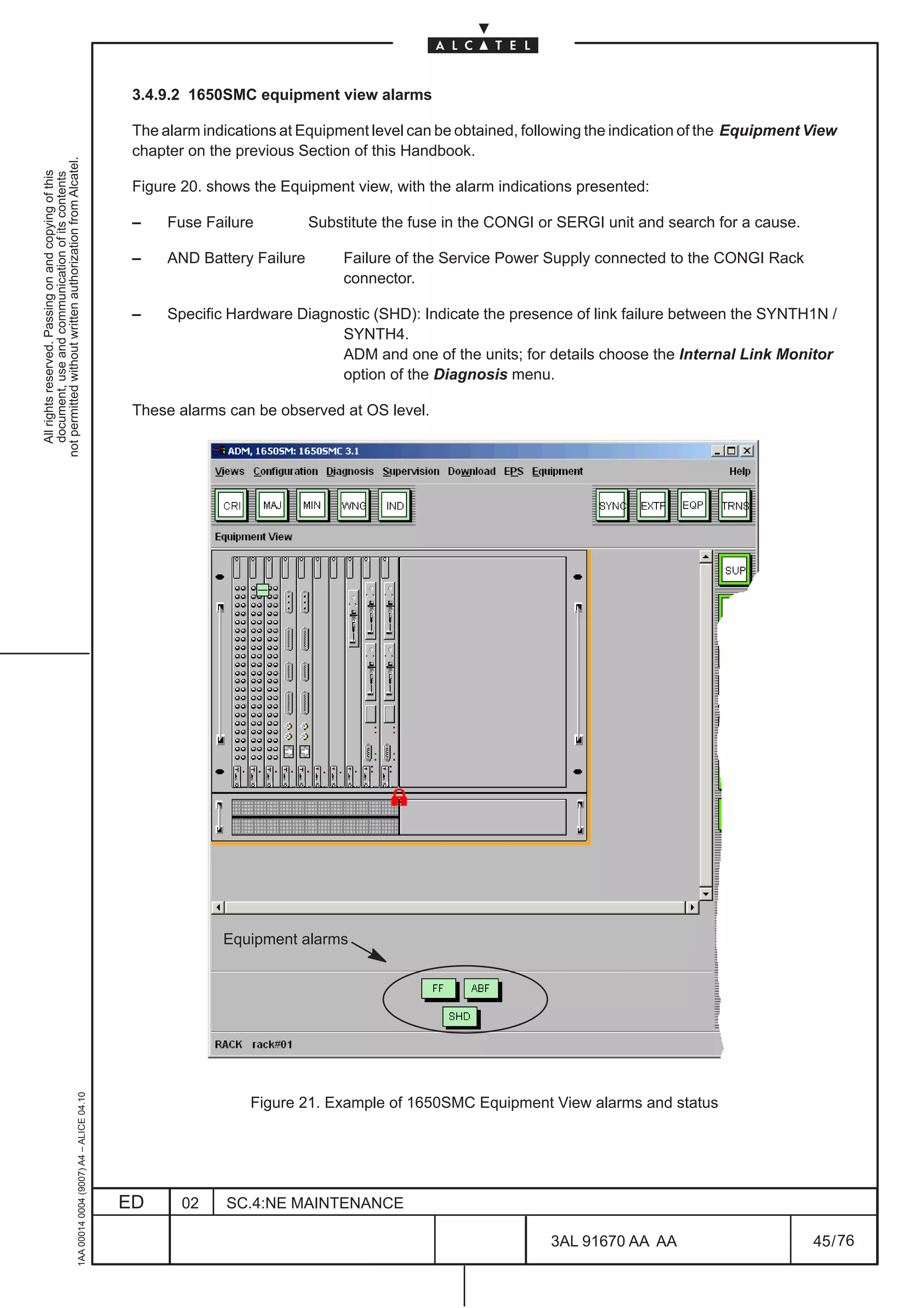

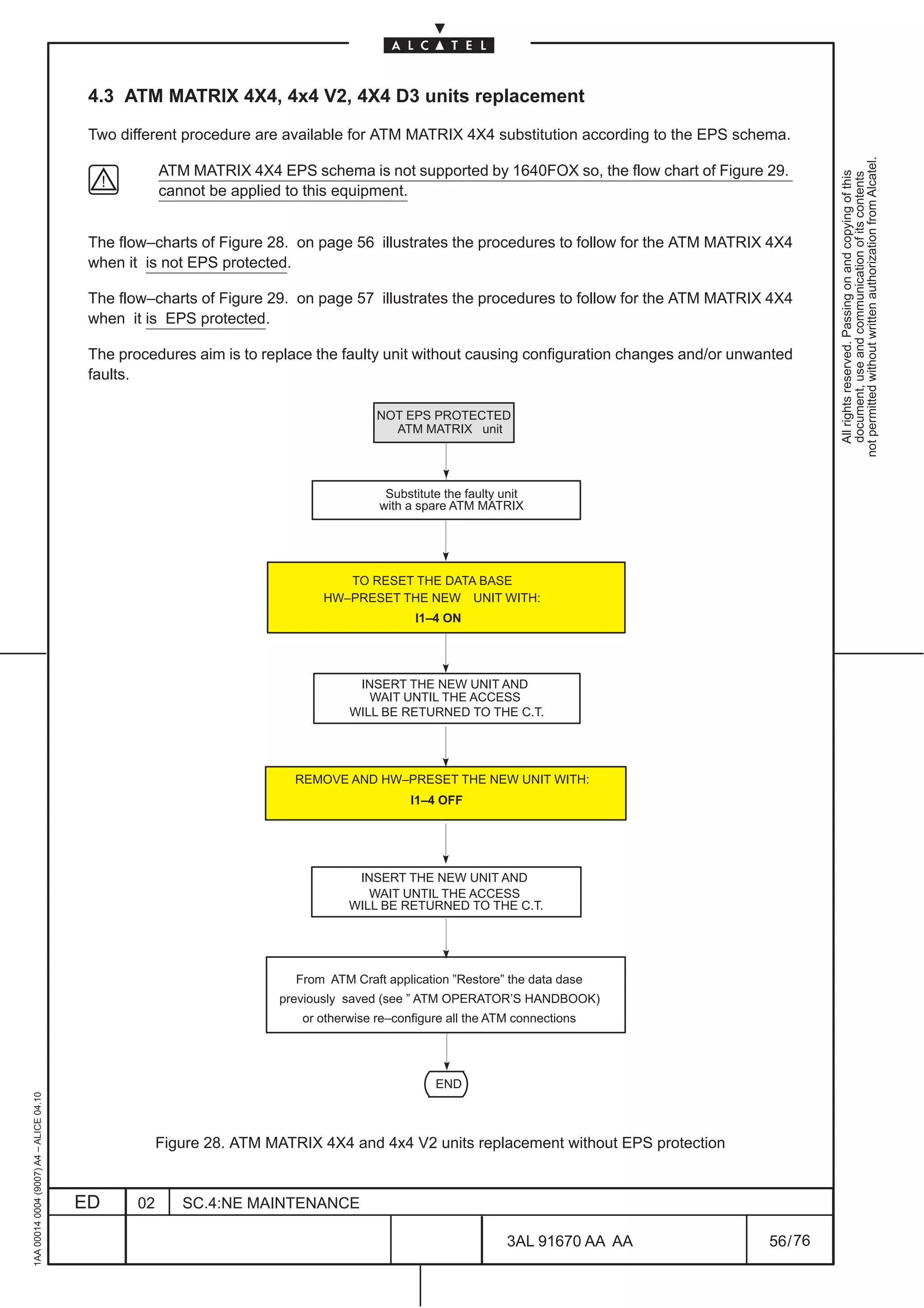
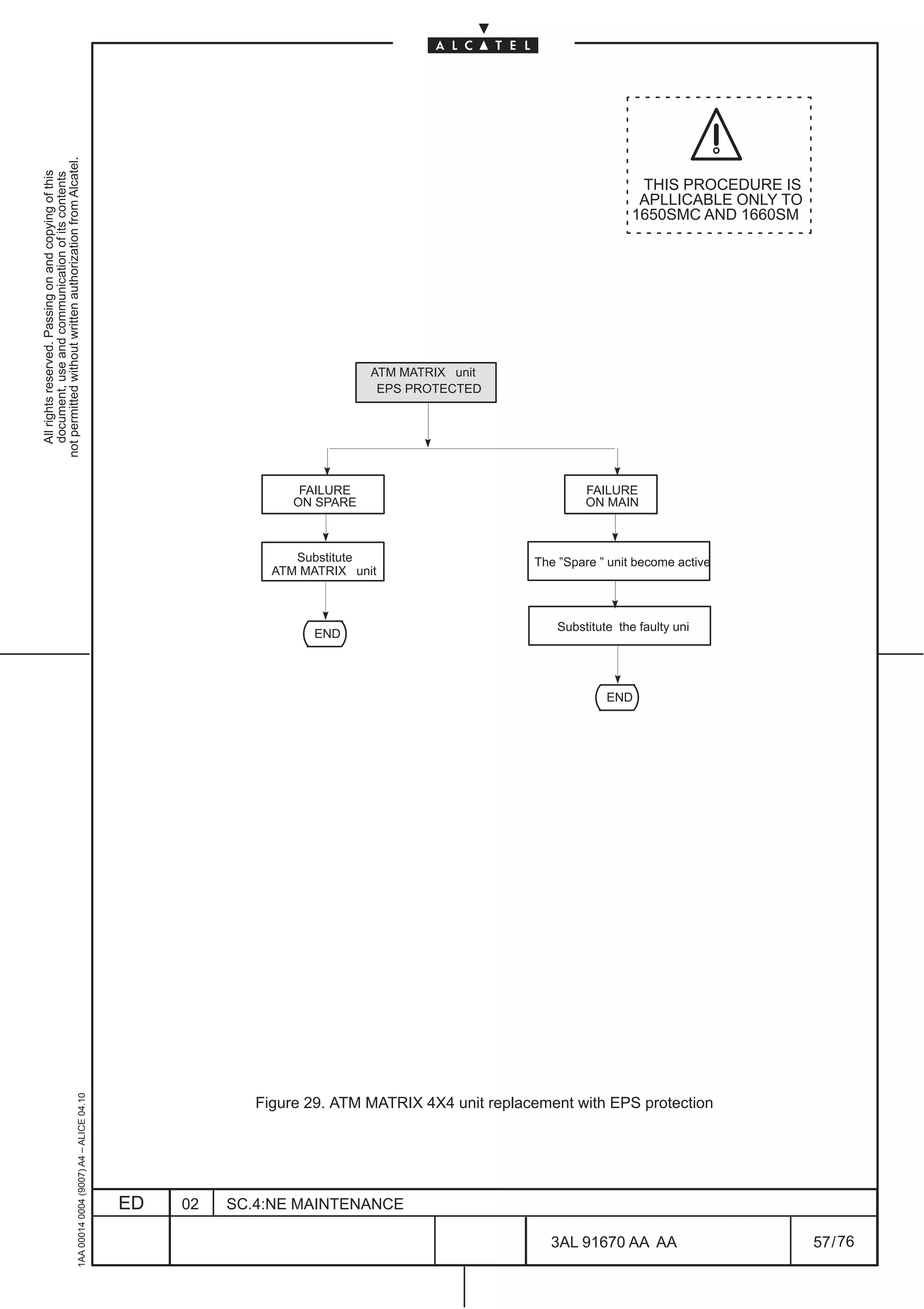
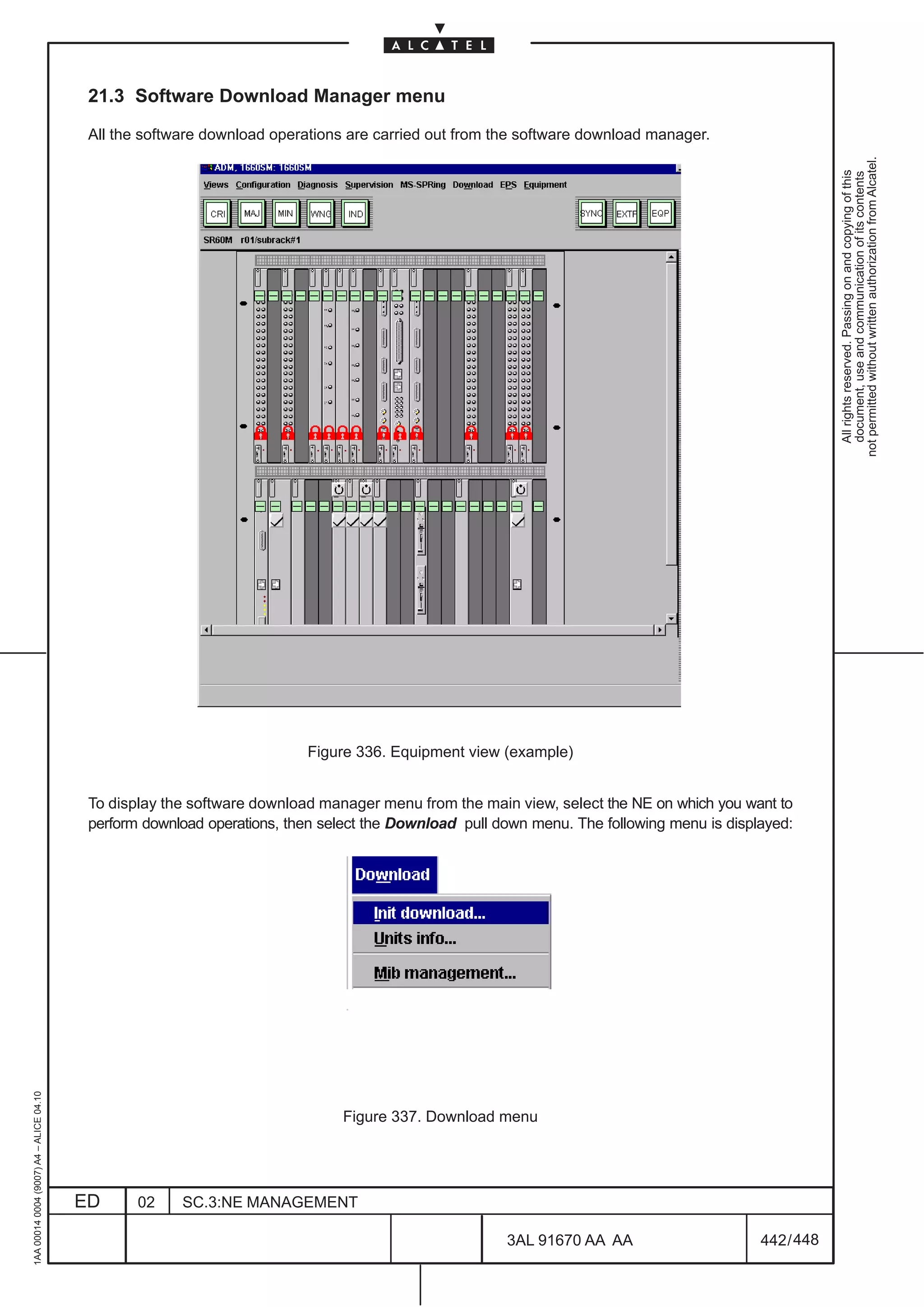
![4.4 ATM MATRIX 8X8 unit replacement
ATM MATRIX 8X8 unit can be equipped only in 1660SM.
not permitted without written authorization from Alcatel.
All rights reserved. Passing on and copying of this
document, use and communication of its contents
Two different procedure are available for ATM MATRIX 8X8 substitution according to the EPS schema.
For ATM MATRIX 8X8 substitution can be applied the same rules used for ATM MATRIX 4X4 , so refer
to flow chart of Figure 28. on page 56 and Figure 29. on page 57.
4.5 CONGI unit replacement
CONGI unit can be equipped only on 1660SM and 1650SMC.
When substituting an “old” CONGI unit (from code 3AL 78830 AAAA to code 3AL 78830 AAAE) with a
“new” CONGI unit (starting from code 3AL 78830 AAAF) must be taken into account the rules reported
in the following; this is necessary for the right management of the “Fuse Broken” alarm on the CONGI
(1650SMC and 1660SM) and SERGI (1650SMC) units.
[1] The alarm “Fuse Broken” is meaningful (hence it is active) only if two batteries connections (this
means that two CONGI in1660SM or one CONGI and one SERGI in 1650SMC has been equipped)
are present.
[2] If “old” CONGI units are present in main slot (slot 10 for 1660SM and slot 4 for 1650SMC) it is manda-
tory to connect the service battery to the front connector (refer to Installation Handbook for details)
to correctly activate the alarms.
[3] In presence of configurations having 2 CONGI units composed of an “old” and “new” type it is manda-
tory to open TC5 setting (refer to Technical Handbook for details on Hardware settings) on the solder-
ing side of the “old” type CONGI if the latter is placed in the spare position (slot 12 in 1660SM and
slot 5 in 1650SMC).
If the “old” CONGI is maintained in a main slot (slot 10 in 1660SM and slot 4 in 1650SMC), TC5 can
be nevertheless closed or open.
1AA 00014 0004 (9007) A4 – ALICE 04.10
ED 02 SC.4:NE MAINTENANCE
3AL 91670 AA AA 58 / 76
76](https://image.slidesharecdn.com/1660smoperr4-452b-100224044515-phpapp01/75/1660-S-M-Oper-R4-554-2048.jpg)
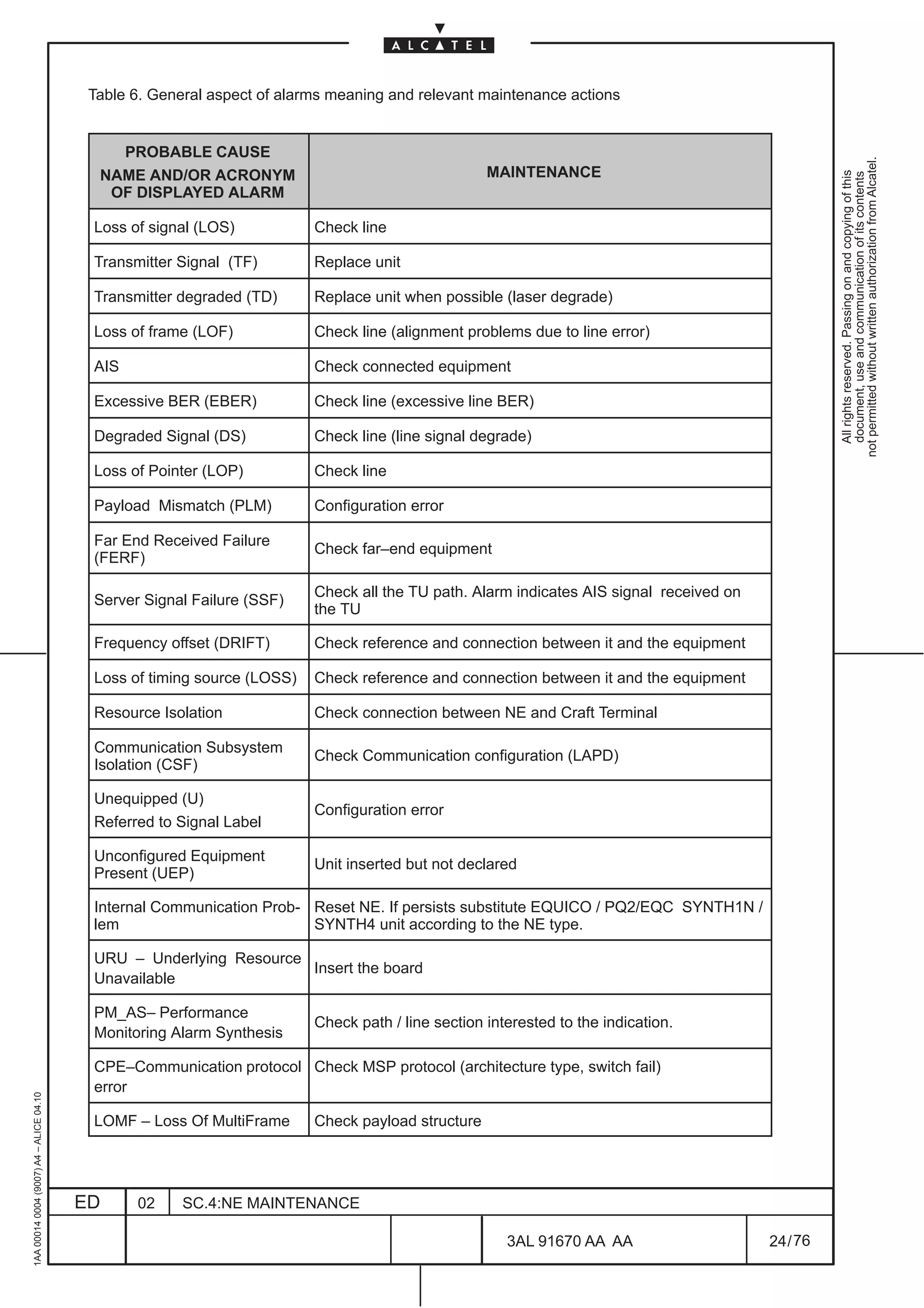
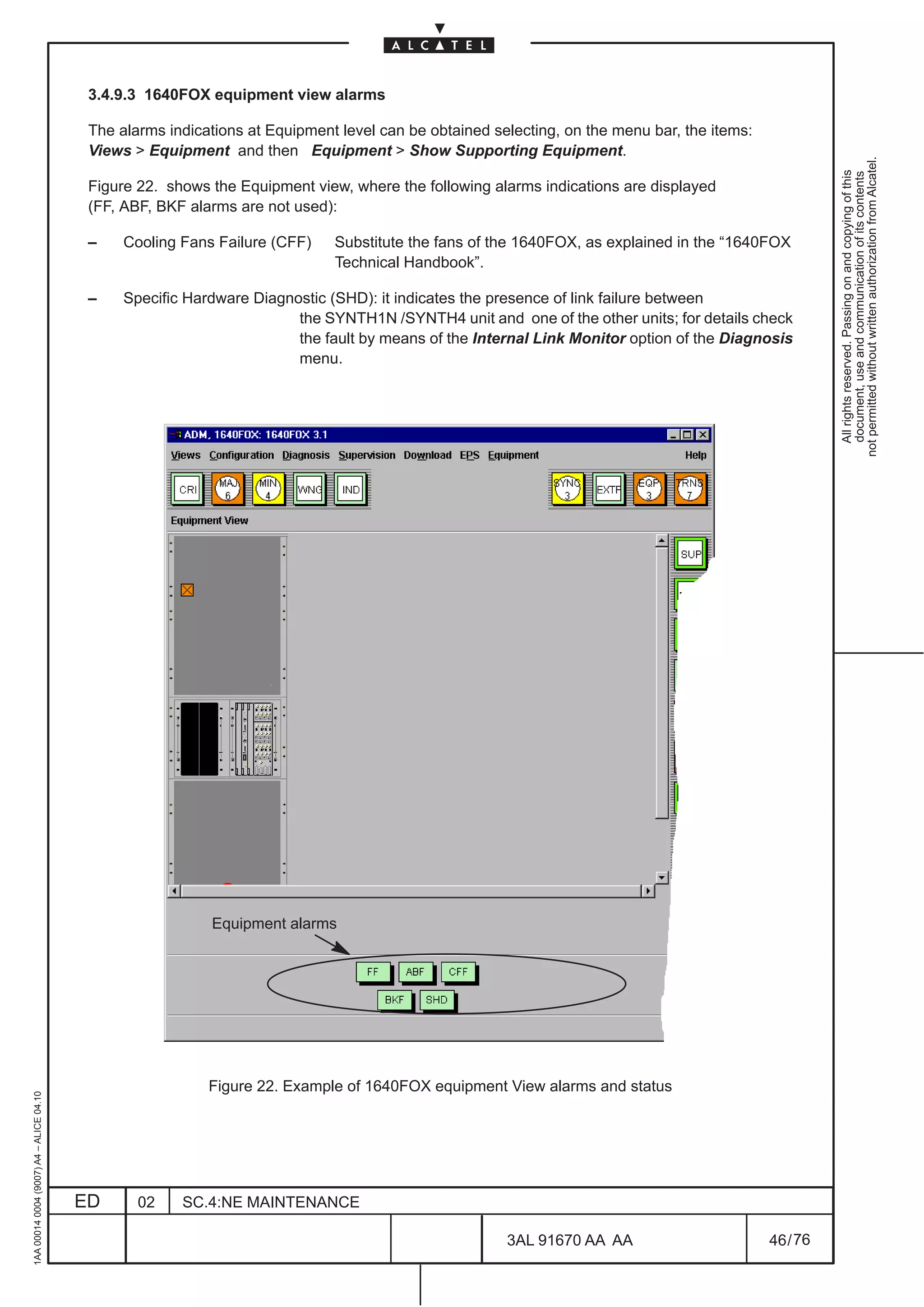
![5.1 MATRIX substitution with MATRIXN
MATRIX unit can be equipped only in 1660SM Rel. 4.3.
not permitted without written authorization from Alcatel.
All rights reserved. Passing on and copying of this
document, use and communication of its contents
According to the MATRIX EPS protection scheme different procedure are available:
[1] Upgrading with a new MATRIXN EPS not protected
Substituting the old MATRIX all the traffic is lost!
• Remove the old MATRIX in slot 23 from the subrack
• Insert the new MATRIX into the subrack slot 23; on Craft Terminal a RUTM (unit type mismatch)
alarm will be present.
• On Craft Terminal in the Subrack level view select the slot where the new unit has been inserted
• Select the Modify option from the Equipment menu and select the acronym of the new unit
( MATRIXN) from the list, then click on ok.
• Verify that the RUTM alarm disappear
[2] Upgrading with a new MATRIXN EPS protected
• Remove first the Stand–by MATRIX from the subrack
• Insert the new MATRIXN into the subrack slot previously occupied by the old MATRIX; a RUTM
(unit type mismatch) alarm will be present.
• On Craft Terminal in the Subrack level view select the slot where the new unit has been inserted
• Select the Modify option from the Equipment menu and select the MATRIXN acronym from
the list then click on ok.
• Verify that the RUTM alarm disappear
• Force the EPS Switching to the Stand–by MATRIXN by selecting the Switch option from the
EPS menu. For details see the paragraph “Switching EPS” in the “NE MANAGEMENT” section
of this Handbook.
• After having verify that the MATRIXN (previously in Stand–by) is now working, remove the MA-
TRIX unit (previously working) from the subrack.
• Insert the new MATRIXN into the subrack slot previously occupied by the old MATRIX; a RUTM
(unit type mismatch) alarm will be present.
• On Craft Terminal in the Subrack level view select the slot where the new unit has been inserted
• Select the Modify option from the Equipment menu and select the MATRIXN acronym from
the list then click on ok.
• Verify that the RUTM alarm disappear
1AA 00014 0004 (9007) A4 – ALICE 04.10
• The decision to force again the EPS MATRIXN switching to restore the original working condi-
tion is left to the operator.
ED 02 SC.4:NE MAINTENANCE
3AL 91670 AA AA 60 / 76
76](https://image.slidesharecdn.com/1660smoperr4-452b-100224044515-phpapp01/75/1660-S-M-Oper-R4-556-2048.jpg)
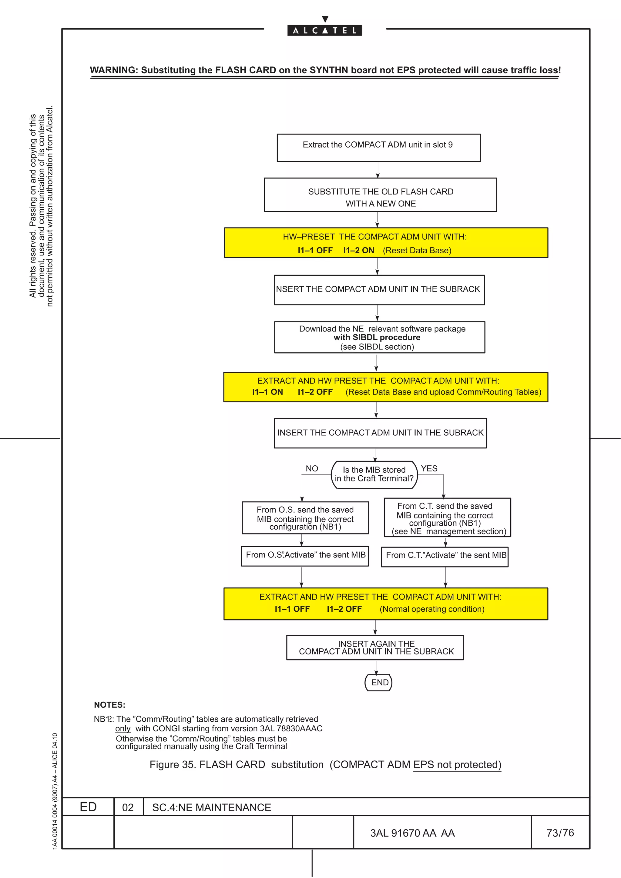
![5.2 SYNTH1 substitution with SYNTH1N
5.2.1 Procedure for 1650SMC
not permitted without written authorization from Alcatel.
All rights reserved. Passing on and copying of this
document, use and communication of its contents
According to the EPS and SNCP SYNTH1 protection scheme different procedure are available:
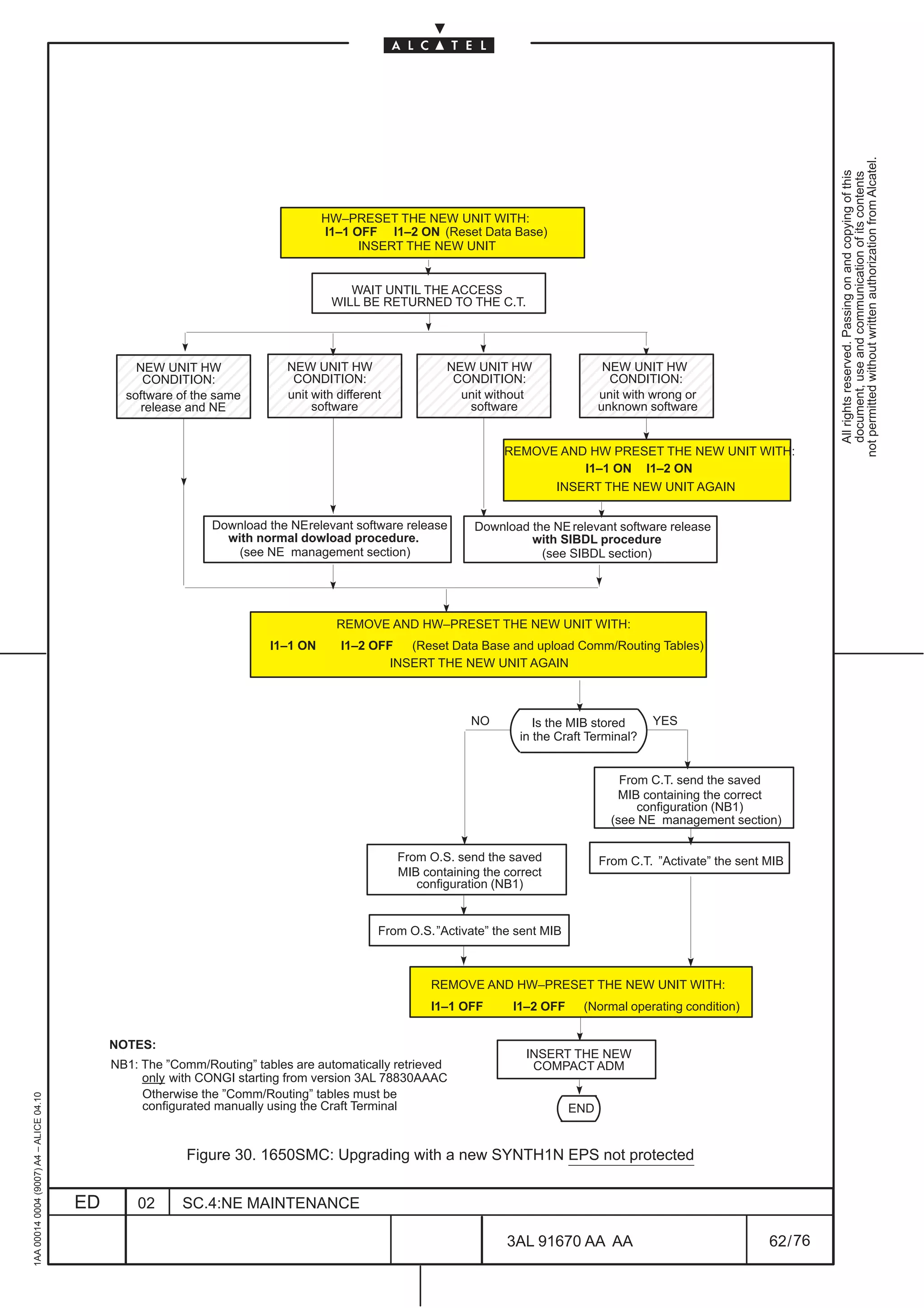
[1] Upgrading with a new SYNTH1N EPS not protected
Substituting the old SYNTH1 all the traffic is lost!
• Remove the old SYNTH1 in slot 9 from the subrack
• Before inserting the new SYNTH1N in subrack slot 9, follow the instruction described in
Figure 30. on page 62. At the end of the procedure a RUTM (unit type mismatch) alarm will be
present.
• On Craft Terminal in the Subrack level view select the SYNTHN unit in slot 9
• Select the Modify option from the Equipment menu and select the SYNTH1N acronym from
the list then click on ok.
• Verify that the RUTM alarm disappear
1AA 00014 0004 (9007) A4 – ALICE 04.10
ED 02 SC.4:NE MAINTENANCE
3AL 91670 AA AA 61 / 76
76](https://image.slidesharecdn.com/1660smoperr4-452b-100224044515-phpapp01/75/1660-S-M-Oper-R4-557-2048.jpg)
![[2] Upgrading with a new SYNTH1N EPS protected
Supposing that the two STM–1 ports are not network protected, their traffic will be lost during the
substitution; the traffic of all the other board will not be lost.
not permitted without written authorization from Alcatel.
All rights reserved. Passing on and copying of this
document, use and communication of its contents
• Remove first the old SYNTH1 in slot 10 from the subrack
• Insert the new SYNTH1N into the subrack slot 10; a RUTM (unit type mismatch) alarm will be
present.
• On Craft Terminal in the Subrack level view select the SYNTH1N unit in slot 10
• Select the Modify option from the Equipment menu and select the SYNTH acronym from the
list then click on ok.
• Verify that the RUTM alarm disappear
• Force the EPS Switching on SYNTH1N in slot 10 by selecting the Switch option from the EPS
menu. For details see the paragraph “Switching EPS” in the “NE MANAGEMENT” section of
this Handbook.
• Remove the old SYNT1H in slot 9 from the subrack
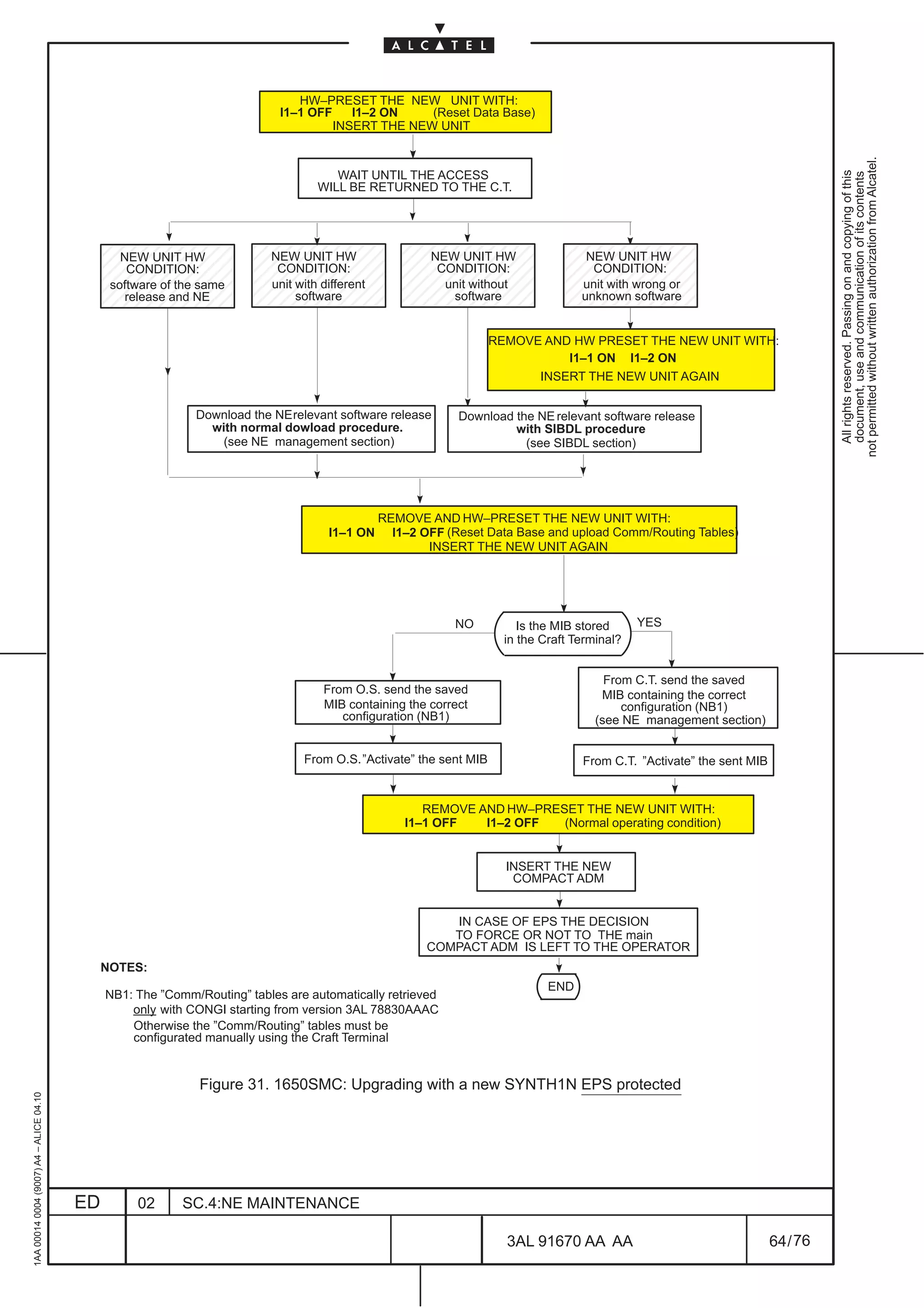
• Before inserting the new SYNTH1N in subrack slot 9, follow the instruction described in
Figure 31. on page 64. At the end of the procedure a RUTM (unit type mismatch) alarm will be
present.
• On Craft Terminal in the Subrack level view select the SYNTH1N unit in slot 9
• Select the Modify option from the Equipment menu and select the SYNTH1N acronym from
the list then click on ok.
• Verify that the RUTM alarm disappear
1AA 00014 0004 (9007) A4 – ALICE 04.10
ED 02 SC.4:NE MAINTENANCE
3AL 91670 AA AA 63 / 76
76](https://image.slidesharecdn.com/1660smoperr4-452b-100224044515-phpapp01/75/1660-S-M-Oper-R4-559-2048.jpg)


![not permitted without written authorization from Alcatel.
All rights reserved. Passing on and copying of this
document, use and communication of its contents
C:ALCATELQ3CT_Pv1.3.05/FTservices/data/1660SME/2.1b.09/1660.dsc
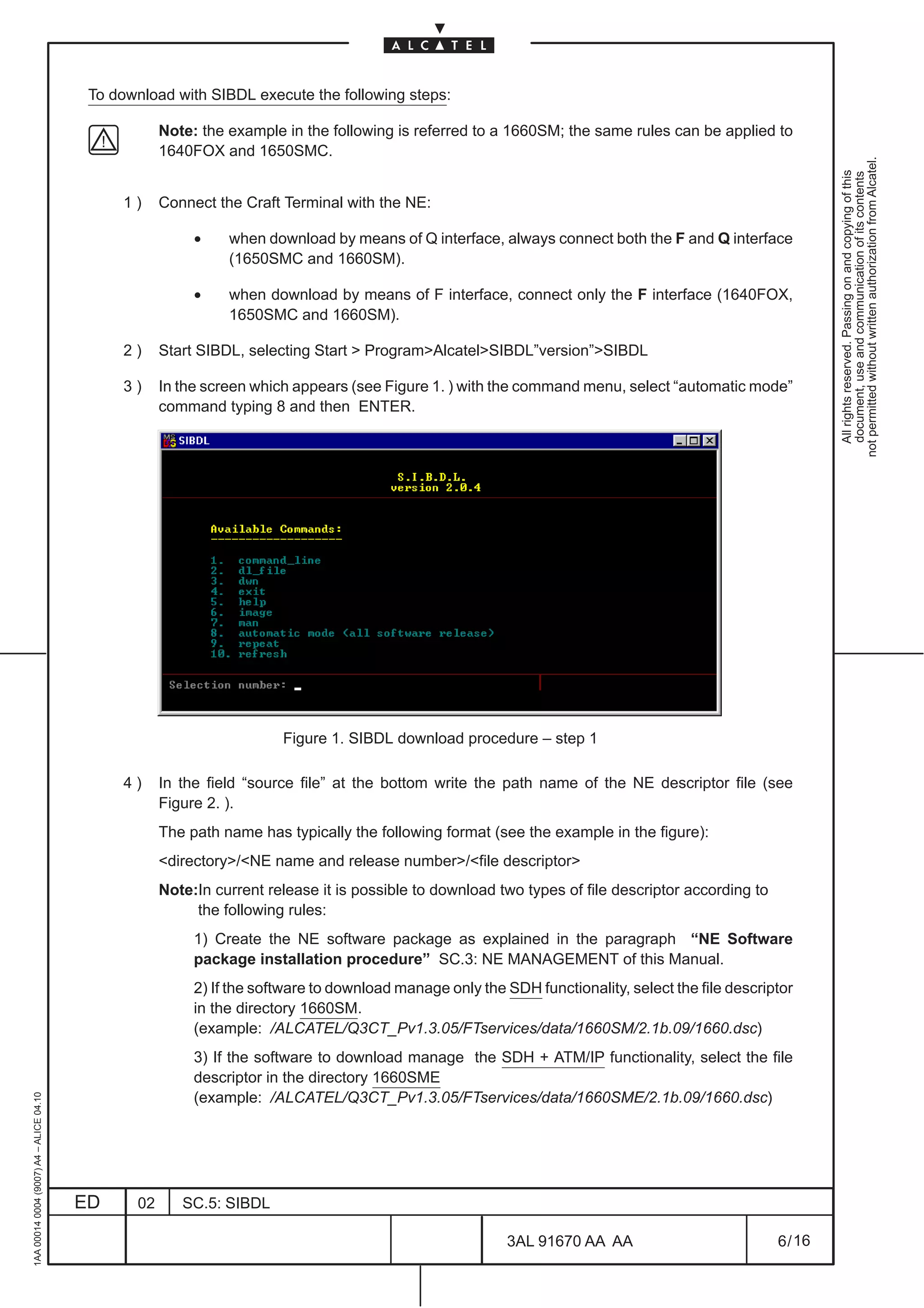
Figure 2. SIBDL download procedure – step 2
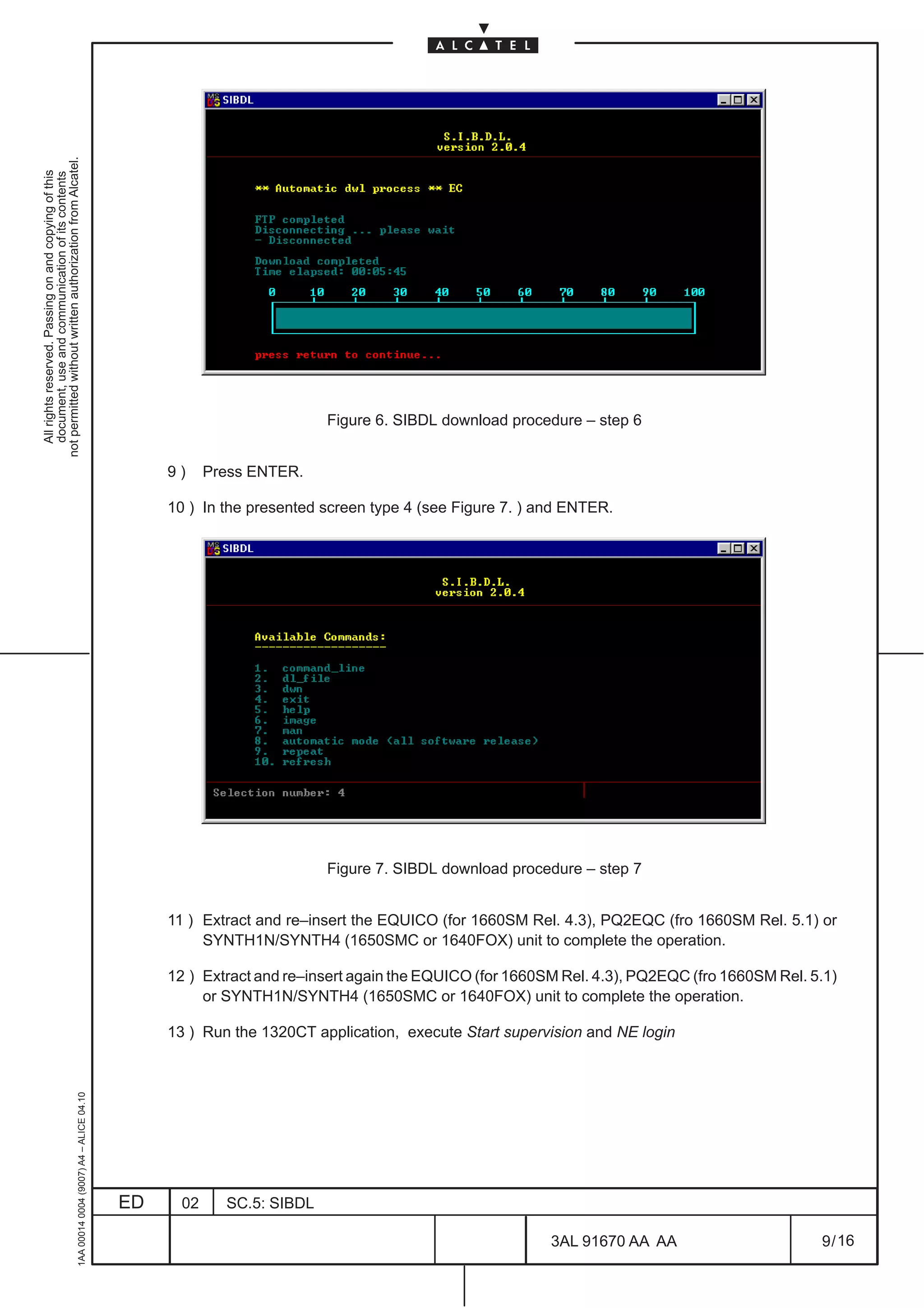
5) Press ENTER
6) This step (see Figure 3. ) ask for the “IP Address” insertion.
In the field “NE_IP_address[ PPP TEL NET]” at the bottom:
– with F interface: write PPP and press ENTER
– with Q interface (only1650SMC and 1660SM):
• first possibility: write TELNET and press ENTER
In next step which appears write the IP Address of the Craft Terminal
• second possibility: write the IP Address of the NE and press ENTER
ervices/data/1660SME/2.1b.09/1660.dsc
Figure 3. SIBDL download procedure – step 3
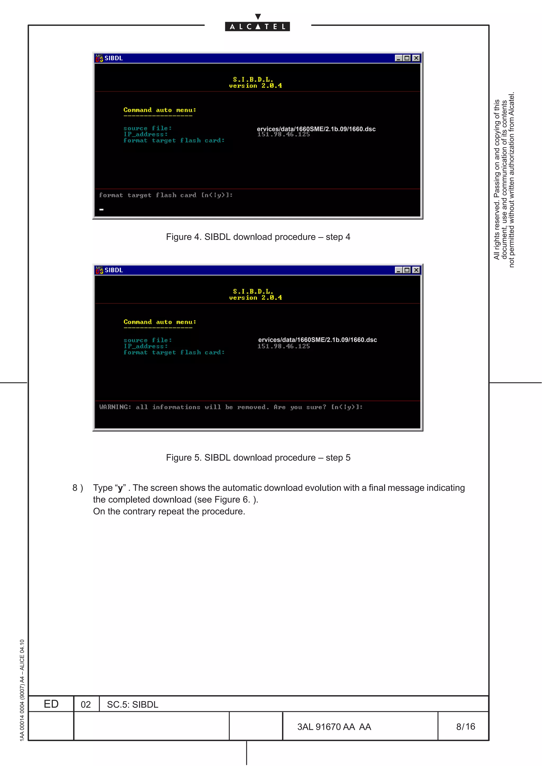
7) This step ( see Figure 4. ) ask if the flash card must be formatted.
1AA 00014 0004 (9007) A4 – ALICE 04.10
Type “y” to format the flash card; as result of this action the program ask for a confirmation (see
Figure 5. )
ED 02 SC.5: SIBDL
3AL 91670 AA AA 7 / 16
16](https://image.slidesharecdn.com/1660smoperr4-452b-100224044515-phpapp01/75/1660-S-M-Oper-R4-579-2048.jpg)


![Dicas De Configuração S D H Lucent A D M[1]](https://cdn.slidesharecdn.com/ss_thumbnails/dicasdeconfiguraosdhlucentadm1-100224044502-phpapp02-thumbnail.jpg?width=640&height=640&fit=bounds)


