Downloaded 12 times
![Power Optimized ALU Design with Control-Signal
Gating Technique for Efficient Datapath
Anil Kumar Yadav
Department of Electronics Engineering
Pondicherry University
Pondicherry, India.
anil8210yadav@gmail.com
Mohammed Aneesh Y.
Department of Electronics Engineering
Pondicherry University
Pondicherry, India.
aneeshssw1@gmail.com
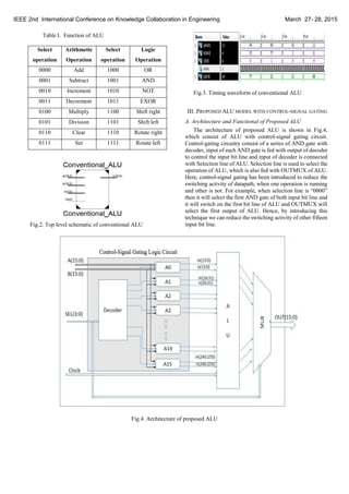
Abstract— In this paper, we have presented an ALU
(Arithmetic and Logic Unit) with a control-signal gating
technique for reducing the switching activity on datapath buses.
The main idea behind this logic is the control-signal gating
technique that will detect the bus, which is not going to be used
and it will turn on only that unit which is functioning and
switch-off the module which is not functioning. Control-gating
circuit employs a series of AND gate on the input bus line which
is controlled by a decoder. We have compared the dynamic
power of proposed ALU model with conventional ALU by
considering target FPGA device Virtex-6 low power with speed
grade -1L.
Keywords— control-signal gating, data buses, low power,
switching activity, dynamic power.
I. INTRODUCTION
ALU is one of the basic blocks and crucial component of all
the processing unit. It mainly consists of a number of
functional units, for different arithmetic, logic and shift
operation, making it the hot spot of datapath. An important
part of energy is wasted in the datapath due to switching
activity that does not contribute to the functionality of the
circuit, causing power dissipation.
Power dissipation consists of two components: static power
and dynamic power. Dynamic power is also called as
switching power which is dissipated due to the switching
activity. Dynamic power is defined as:
Pdynamic = α * c * v2
*f (1)
In equation (1): α is the switching activity, c the capacitance,
v the supply voltage and f the frequency of operation. From
the relation, it is observed that the dynamic power is
proportional to the frequency and the switching activity.
Thus, the possible solution to reduce power could be achieve
by reducing the switching activity and not the frequency as,
devices need to operate at high speed.
There are different technique which has been proposed to
suppress this switching activity like Pre-computational logic,
guarded evaluation etc. [6]. To reduce the power on datapath
buses, it is necessary to employ a technique that can reduce
its switching activity. So, here we introduces a method that
can be used for reducing the switching activity on datapath
buses, named control-signal gating technique.
The control-signal technique implements the advantage of a
fine granularity analysis to minimize the switching activity of
the datapath buses which is based on the observability don’t
care concept (ODC) to detect the bus when it is not going to
be use and to block the propagation of the switching activity
through the module(s) driving the bus [1]. There are different
ways to employ control-signal gating. The simplest one is to
put an AND/ OR gate at the signal path to stop the
propagation of signal, when there is no need of it. Another
method is to use a latch or flip-flop to stop the propagation of
the signal. Sometimes, a transmission gate or a tristate buffer
can be used in place of a latch if charge leakage is not a
concern. All signal gating method requires control signals to
stop the propagation of switching activities as shown in
Fig.1.
The proposed control-signal gating circuit consists of a series
of AND Control gates which is controlled by a decoder. The
output of decoder is connected to one of the inputs of the
AND gate and input of decoder is connected to the selection
line of the ALU, which is act as a controlling signal for this
logic circuit and other input of the AND gate.
Fig.1. Control-Signal Gating Technique
II. CONVENTIONAL16-BIT ALU
We have introduced a conventional 16-bit ALU to compare
the results of proposed ALU model. Conventional 16-bit ALU
consists of sixteen operational blocks, whose operation has
been explained in Table I. and it is simulated in Xilinx Tool,
whose top level schematic (RTL) view and timing waveform
is shown in Fig.2 and Fig.3.
IEEE 2nd International Conference on Knowledge Collaboration in Engineering March 27- 28, 2015
978-1-4799-8619-4/15/$31.00 ©2015 IEEE](https://image.slidesharecdn.com/127ece-150412103324-conversion-gate01/85/Power-Optimized-ALU-Design-with-Control-Signal-Gating-Technique-for-Efficient-Datapath-1-320.jpg)
![Power Optimized ALU Design with Control-Signal
Gating Technique for Efficient Datapath
Anil Kumar Yadav
Department of Electronics Engineering
Pondicherry University
Pondicherry, India.
anil8210yadav@gmail.com
Mohammed Aneesh Y.
Department of Electronics Engineering
Pondicherry University
Pondicherry, India.
aneeshssw1@gmail.com
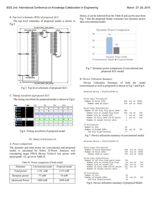
Abstract— In this paper, we have presented an ALU
(Arithmetic and Logic Unit) with a control-signal gating
technique for reducing the switching activity on datapath buses.
The main idea behind this logic is the control-signal gating
technique that will detect the bus, which is not going to be used
and it will turn on only that unit which is functioning and
switch-off the module which is not functioning. Control-gating
circuit employs a series of AND gate on the input bus line which
is controlled by a decoder. We have compared the dynamic
power of proposed ALU model with conventional ALU by
considering target FPGA device Virtex-6 low power with speed
grade -1L.
Keywords— control-signal gating, data buses, low power,
switching activity, dynamic power.
I. INTRODUCTION
ALU is one of the basic blocks and crucial component of all
the processing unit. It mainly consists of a number of
functional units, for different arithmetic, logic and shift
operation, making it the hot spot of datapath. An important
part of energy is wasted in the datapath due to switching
activity that does not contribute to the functionality of the
circuit, causing power dissipation.
Power dissipation consists of two components: static power
and dynamic power. Dynamic power is also called as
switching power which is dissipated due to the switching
activity. Dynamic power is defined as:
Pdynamic = α * c * v2
*f (1)
In equation (1): α is the switching activity, c the capacitance,
v the supply voltage and f the frequency of operation. From
the relation, it is observed that the dynamic power is
proportional to the frequency and the switching activity.
Thus, the possible solution to reduce power could be achieve
by reducing the switching activity and not the frequency as,
devices need to operate at high speed.
There are different technique which has been proposed to
suppress this switching activity like Pre-computational logic,
guarded evaluation etc. [6]. To reduce the power on datapath
buses, it is necessary to employ a technique that can reduce
its switching activity. So, here we introduces a method that
can be used for reducing the switching activity on datapath
buses, named control-signal gating technique.
The control-signal technique implements the advantage of a
fine granularity analysis to minimize the switching activity of
the datapath buses which is based on the observability don’t
care concept (ODC) to detect the bus when it is not going to
be use and to block the propagation of the switching activity
through the module(s) driving the bus [1]. There are different
ways to employ control-signal gating. The simplest one is to
put an AND/ OR gate at the signal path to stop the
propagation of signal, when there is no need of it. Another
method is to use a latch or flip-flop to stop the propagation of
the signal. Sometimes, a transmission gate or a tristate buffer
can be used in place of a latch if charge leakage is not a
concern. All signal gating method requires control signals to
stop the propagation of switching activities as shown in
Fig.1.
The proposed control-signal gating circuit consists of a series
of AND Control gates which is controlled by a decoder. The
output of decoder is connected to one of the inputs of the
AND gate and input of decoder is connected to the selection
line of the ALU, which is act as a controlling signal for this
logic circuit and other input of the AND gate.
Fig.1. Control-Signal Gating Technique
II. CONVENTIONAL16-BIT ALU
We have introduced a conventional 16-bit ALU to compare
the results of proposed ALU model. Conventional 16-bit ALU
consists of sixteen operational blocks, whose operation has
been explained in Table I. and it is simulated in Xilinx Tool,
whose top level schematic (RTL) view and timing waveform
is shown in Fig.2 and Fig.3.
IEEE 2nd International Conference on Knowledge Collaboration in Engineering March 27- 28, 2015
978-1-4799-8619-4/15/$31.00 ©2015 IEEE](https://image.slidesharecdn.com/127ece-150412103324-conversion-gate01/75/Power-Optimized-ALU-Design-with-Control-Signal-Gating-Technique-for-Efficient-Datapath-1-2048.jpg)
![V. CONCLUSION
Hence, we have designed, simulated and compared the result
of both the model using Xilinx Tool and it has been seen that the
ALU with control-signal gating techniques consumes less power
than conventional model. So, it can be concluded that the
proposed model can be utilized as power optimized technique to
reduce the switching activity on datapath buses. There are other
logic circuitry which can be developed and designed in future to
control the switching activity on datapath buses. Future work
includes the implementation of clock gating technique with
control-signal gating technique to reduce the unnecessary
switching activity of clock and datapath buses, when there is no
need of it.
REFERENCES
[1] H. Kapadia, L. Benini, and G. De Micheli, “Reducing
switching activity on datapath buses with control-signal
gating,” IEEE J. Solid-State Circuits, vol. 34, pp. 405–414,
Mar. 1999.
[2] M.Kamaraju, K.Lal Kishore and A.V.N. Tilak “Power
Optimized ALU for Efficient Datapath,” International
Journal of Computer Applications, Vol 11-No-11,
December 2010.
[3] Christian Piguet, “Low-Power CMOS Circuits:
Technology, Logic Design and CAD Tools”, CRC Press,
2005.
[4] Ireneusz Brzozowski, Andrzej Kos, "Minimization of
Power Consumption in Digital Integrated Circuits by
Reduction of Switching Activity", EUROMICRO
Conference 1999, pp. 1376, doi:
10.1109/EURMIC.1999.79449.
[5] W.D. Tseng, “Scan chain ordering technique for switching
activity reduction during scan test” IEEE Proc.-Comput.
Digit. Tech., Vol. 152, No. 5, September 2005.
[6] Vasily G. Moshnyaga and Keikichi Tamaru,“A
Comparative Study of Switching Activity Reduction
Techniques for Design of Low-Power Multipliers”, IEEE
International Symposium on Circuits and Systems, ISCAS
'95., 1995.
[7] Pietro Babighian, Luca Benini, Enrico Macii, “A Scalable
Algorithm for RTL Insertion of Gated Clocks Based on
ODCs Computation”, IEEE Trans. Computer-Aided
Design, Vol. 24, No.1, 2005, pp.29-42.
[8] Javier Castro, Pilar Parra, and Antonio J. Acosta,
“Optimization of clock-gating Structures for low leakage
high-performance Applications”, IEEE International
Symposium on Circuit and System, pp. 3320-3223, May
10, 2010.
IEEE 2nd International Conference on Knowledge Collaboration in Engineering March 27- 28, 2015](https://image.slidesharecdn.com/127ece-150412103324-conversion-gate01/85/Power-Optimized-ALU-Design-with-Control-Signal-Gating-Technique-for-Efficient-Datapath-4-320.jpg)

This paper presents a power-optimized ALU design using a control-signal gating technique to reduce switching activity on datapath buses. The proposed ALU model shows improved dynamic power consumption compared to a conventional ALU model, making it a viable solution for power efficiency in digital circuits. Future work will explore integrating clock gating techniques to further minimize unnecessary switching activities.


![[IJET-V1I3P5] Authors :Dushyant Kumar Soni, Ashish Hiradhar](https://cdn.slidesharecdn.com/ss_thumbnails/ijet-v1i3p5-150519153226-lva1-app6891-thumbnail.jpg?width=640&height=640&fit=bounds)