A static loadis defined as a force, which is gradually applied to a mechanical component and
which does not change its magnitude or direction with respect to time.
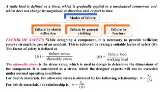
Modes of failure
failure by elastic
deflection
failure by general
yielding
failure by
fracture
FACTOR OF SAFETY: While designing a component, it is necessary to provide sufficient
reserve strength in case of an accident. This is achieved by taking a suitable factor of safety (fs).
The factor of safety is defined as
The allowable stress is the stress value, which is used in design to determine the dimensions of
the component. It is considered as a stress, which the designer expects will not be exceeded
under normal operating conditions
For ductile materials, the allowable stress is obtained by the following relationship:
For brittle materials, the relationship is,
3.
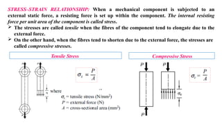
STRESS–STRAIN RELATIONSHIP: Whena mechanical component is subjected to an
external static force, a resisting force is set up within the component. The internal resisting
force per unit area of the component is called stress.
The stresses are called tensile when the fibres of the component tend to elongate due to the
external force.
On the other hand, when the fibres tend to shorten due to the external force, the stresses are
called compressive stresses.
Tensile Stress Compressive Stress
4.
The strain isdeformation per unit length. It given by
According to Hooke’s law, the stress is directly proportional to the strain within elastic limit.
Therefore,
where E is the constant of proportionality known as Young’s modulus or modulus of elasticity
(in N/mm2 or MPa).
SHEAR STRESS AND SHEAR STRAIN: When the external force acting on a component tends
to slide the adjacent planes with respect to each other, the resulting stresses on these planes are
called direct shear stresses.
5.
The shear strainis defined as the change in the right angle of a shear element. Within the elastic
limit, the stress–strain relationship is given by
STRESSES DUE TO BENDING MOMENT: A straight beam subjected to a bending moment Mb
is shown in Figure below. The beam is subjected to a combination of tensile stress on one side of
the neutral axis and compressive stress on the other. The bending stress at any fibre is given by:
6.
STRESSES DUE TOTORSIONAL MOMENT: A transmission shaft, subjected to an external
torque, is shown in Figure below. The internal stresses, which are induced to resist the action of
twist, are called torsional shear stresses. The torsional shear stress is given by:
ECCENTRIC AXIAL LOADING: There are certain
mechanical components subjected to an external force,
tensile or compressive, which does not pass through the
centroid of the cross-section. A typical example of such an
eccentric loading is shown in Figure aside. The resultant
stresses at the cross-section are obtained by the principle
of superimposition of stresses. They are given by,
There arenumber of machine components, which are subjected to several types of
loads simultaneously.
For example, a power screw is subjected to torsional moment as well as axial force.
Similarly, an overhang crank is subjected to combined bending and torsional
moments. The bolts of the bracket are subjected to forces that cause tensile stress
and shear stress. Crankshaft, propeller shaft and connecting rod are examples of
components subjected to complex loads.
When the component is subjected to several types of loads, combined stresses are
induced. For example, torsional moment induces torsional shear stress, while
bending moment causes bending stresses in the transmission shaft.
Theories of Elastic Failure
10.
The designof machine parts subjected to combined loads should be related to
experimentally determined properties of material under ‘similar’ conditions.
However, it is not possible to conduct such tests for different possible combinations
of loads and obtain mechanical properties.
In practice, the mechanical properties are obtained from a simple tension test. They
include yield strength, ultimate tensile strength and percentage elongation. In the
tension test, the specimen is axially loaded in tension. It is not subjected to either
bending moment or torsional moment or a combination of loads.
Theories of elastic failure provide a relationship between the strength of machine
component subjected to complex state of stresses with the mechanical properties
obtained in tension test.
With the help of these theories, the data obtained in the tension test can be used to
determine the dimensions of the component, irrespective of the nature of stresses
induced in the component due to complex loads.
11.
Theories of ElasticFailure
The principal theories of elastic failure are as follows:
1. Maximum principal (or normal) stress theory (also known as Rankine’s
theory).
2. Maximum shear stress theory (also known as Guest’s or Tresca’s theory).
3. Maximum principal (or normal) strain theory (also known as
Saint Venant theory).
4. Maximum strain energy theory (also known as Haigh’s theory).
5. Maximum distortion energy theory (also known as Hencky and Von Mises
theory).
12.
Maximum Principal StressTheory
The theory states that the failure of the mechanical component
subjected to bi-axial or tri-axial stresses occurs when the maximum
principal stress reaches the yield or ultimate strength of the material.
Region of Safety
13.
Maximum Shear StressTheory
The theory states that the failure of a mechanical component subjected to bi-axial
stresses occurs when the maximum shear stress at any point in the component
becomes equal to the maximum shear stress in the standard specimen of the
tension test, when yielding starts.
τmax = τyt
/ fs (or)
τmax = Syt
/ (fs2) (or)
(σ1-σ2)/2 = Syt /(fs×2)
(or) Region of Safety
𝑺𝒚𝒕
𝝈𝟏 − 𝝈𝟐 =
(𝒇𝒔)
14.
Maximum Distortion EnergyTheory
The theory states that the failure of the mechanical component subjected to bi-
axial stresses occurs when the strain energy of distortion per unit volume at any
point in the component, becomes equal to the strain energy of distortion per unit
volume in the standard specimen of tension-test, when yielding starts.
Region of Safety
FOR BI-AXIAL STRESSES
15.
Maximum Principal StrainTheory
According to this theory, the failure or yielding occurs at a point in a member
when the maximum principal (or normal) strain in a bi-axial stress system
reaches the limiting value of strain (i.e. strain at yield point) as determined from
a simple tensile test.
ε1 = εyt
(or)
Region of Safety
𝑺𝒚𝒕
𝝈𝟏 − 𝝁𝝈𝟐
=
(𝒇𝒔)
16.
Maximum Strain EnergyTheory
According to this theory, the failure or yielding occurs at a point in a member
when the strain energy per unit volume in a bi-axial stress system reaches the
limiting strain energy (i.e. strain energy at the yield point ) per unit volume as
determined from simple tension test.
Region of Safety
𝑺𝒚
𝒕
(𝒇𝒔
)
𝟏
= 𝝈𝟐 − 𝟐𝝁𝝈
𝝈
𝟏
𝟐
�
�
+
𝝈𝟐
S.No. Name ofthe Failure Theory Governing Equation Region of Safety Shape of ROS
1
Maximum principal (or
normal) stress theory (also
known as Rankine’s theory)
Square
2
Maximum shear stress theory
(also known as Guest’s or
Tresca’s theory)
𝑺𝒚𝒕
𝝈𝟏 − 𝝈𝟐 =
(𝒇𝒔) Hexagon
3
Maximum distortion energy
theory (also known as Hencky
and Von Mises theory)
Ellipse
4
Maximum principal (or
normal) strain theory (also
known as Saint Venant theory)
𝑺𝒚𝒕
𝝈𝟏 − 𝝁𝝈𝟐 =
(𝒇𝒔)
Rhombus
5
Maximum strain energy
theory (also known as Haigh’s
theory)
𝑺𝒚𝒕
= 𝝈𝟐 − 𝟐𝝁𝝈
𝝈 + 𝝈𝟐 (𝒇𝒔)
𝟏 𝟏
𝟐 𝟐
Ellipse
Fluctuating Stresses
Inmany applications, the components are subjected to forces, which are not static, but vary
in magnitude with respect to time. The stresses induced due to such forces are called
fluctuating stresses.
Consider a rotating beam of circular cross-section
and carrying a load W, as shown in Figure aside.
This load induces stresses in the beam which are
cyclic in nature. A little consideration will show that
the upper fibres of the beam (i.e. at point A) are
under compressive stress and the lower fibres (i.e. at
point B) are under tensile stress.
After half a revolution, the point B occupies the position of point A and the point A occupies
the position of point B. Thus the point B is now under compressive stress and the point A
under tensile stress. The speed of variation of these stresses depends upon the speed of the
beam.
From above we see that for each revolution of the beam, the stresses are reversed from
compressive to tensile. The stresses which vary from one value of compressive to the
same value of tensile or vice versa, are known as completely reversed or cyclic stresses.
ENDURANCE LIMIT
The fatigueor endurance limit of material is defined as the
maximum amplititude of completely reversed stress that the
standard specimen can sustain for an unlimited number of cycles
without fatigue failure .
24.
Factor of Safetyfor Fatigue Loading
Stress Concentration
Whenever a machine component changes the shape of its cross-section, the simple
stress distribution no longer holds good and the neighbourhood of the discontinuity is
different. This irregularity in the stress distribution caused by abrupt changes of form
is called stress concentration. It occurs for all kinds of stresses in the presence of
fillets, notches, holes, keyways, splines, surface roughness or scratches etc.
Methods of ReducingStress Concentration
Additional notches and holes in the Tension Members
Fillet Radius, under cutting and notch for members subjected to bending
moment
27.
Drilling of Additionalholes for
shaft
Reduction of stress concentration in threaded
members
Soderberg Method forCombination of Stresses
The Soderberg method is particularly used for ductile
materials.
The following equation is applicable to ductile
materials subjected to reversed bending load (tensile or
compressive).
When a machine component is subjected to reversed
axial loading, then the above equation may be written
as
When a machine component is subjected to reversed
shear loading, then equation may be written as
30.
Goodman Method forCombination of Stresses
A Goodman line is used when the design is based on
ultimate strength and may be used for ductile or brittle
materials.
The following equation is applicable to ductile
materials subjected to reversed bending loads (tensile
or compressive).
For brittle materials, the theoretical stress
concentration factor (Kt) should be applied to the
mean stress and fatigue stress concentration factor (Kf)
to the variable stress. Thus for brittle materials, the
equation
31.
When a machinecomponent is subjected to a load other than reversed bending, then the
endurance limit for that type of loading should be taken into consideration. Thus for
reversed axial loading (tensile or compressive), the following equations may be used for
design
Similarly, for reversed torsional or shear loading,
32.
Gerber Method forCombination of Stresses
A parabolic curve drawn between the endurance limit (σe) and ultimate tensile strength (σu) was
proposed by Gerber in 1874. Generally, the test data for ductile material fall closer to Gerber
parabola as shown in Figure below, but because of scatter in the test points, a straight line
relationship (i.e. Goodman line and Soderberg line) is usually preferred in designing machine parts.
33.
Factors to beconsidered while designing machine parts to avoid fatigue failure
1. The variation in the size of the component should be as gradual as possible.
2. The holes, notches and other stress raisers should be avoided.
3. The proper stress de-concentrators such as fillets and notches should
be provided wherever necessary.
4. The parts should be protected from corrosive atmosphere.
5. A smooth finish of outer surface of the component increases the fatigue life.
6. The material with high fatigue strength should be selected.
7. The residual compressive stresses over the parts surface increases its fatigue
strength.
A cotterjoint is used to connect two co-axial rods, which are subjected to either
axial tensile force or axial compressive force.
It is also used to connect a rod on one side with some machine part
like a crosshead or base plate on the other side.
It is not used for connecting shafts that rotate and transmit torque.
Typical applications of cotter joint are as follows:
(i) Joint between the piston rod and the crosshead of a steam engine
(ii) Joint between the slide spindle and the fork of the valve mechanism
(iii) Joint between the piston rod and the tail or pump rod
(iv) Foundation bolt
Cotter Joint
39.
Design Procedure forCotter Joint
(i) Calculate the diameter of each rod by the following Eq.
(ii) Calculate the thickness of the cotter by the empirical
relationship given by
(iii) Calculate the diameter d2 of the spigot on the basis
of tensile stress using the following Eq.
40.
(iv) Calculate theoutside diameter d1 of the socket on
the basis of tensile stress in the socket, from the Eq.
(v) The diameter of the spigot collar d3 and the
diameter of the socket collar d4 are calculated by the
following empirical relationships,
(vi) The dimensions a and c are calculated by the
following empirical relationship,
41.
(vii) Calculate thewidth b of the cotter by shear consideration and bending consideration
using the Eqs. and select the width, whichever is maximum between these two values.
42.
(viii) Check thecrushing and shear stresses in the
spigot end by the following Eqs.
(ix) Check the crushing and shear stresses in the
socket end by the following Eqs.
43.
(x) Calculate thethickness t1 of the spigot collar by the following empirical relationship,
The taper of the cotter is 1 in 32.
Problem: It is required to design a cotter joint
to connect two steel rods of equal diameter.
Each rod is subjected to an axial tensile force
of 50 kN. Design the joint and specify its
main dimensions. The material of the two
rods and the cotter is selected as plain carbon
steel of Grade 30C8 (Syt = 400 N/mm2). The
factor of safety for the rods, spigot end and
socket end is assumed as 6, while for the
cotter, it is taken as 4. Assume Syc = 2 Syt.
44.
Knuckle Joint
Knucklejoint is used to connect two rods whose axes either coincide or intersect and lie in
one plane. The knuckle joint is used to transmit axial tensile force.
The construction of this joint permits limited angular movement between rods, about the
axis of the pin.
This type of joint is popular in machines and structures.
Typical applications of knuckle joints are as follows:
(i) Joints between the tie bars in roof trusses.
(ii) Joints between the links of a suspension bridge.
(iii) Joints in valve mechanism of a reciprocating engine.
(iv) Fulcrum for the levers.
(v) Joints between the links of a bicycle chain.
46.
Design Procedure forKnuckle Joint
(i) Calculate the diameter of each rod by the following Equation 𝑫
=
(ii) Calculate the enlarged diameter of each rod by empirical relationship using Equation D1 = 1.1 D
(iii) Calculate the dimensions a and b by empirical relationship using the following Equations.
a = 0.75 D & b = 1.25 D
(iv)Calculate the diameters of the pin by shear consideration and bending consideration and
select the diameter, whichever is maximum.
𝟒
𝑷
𝝅
𝝈𝒕
47.
(v) Calculate thedimensions do and d1 by using following empirical relationships do = 2d & d1 = 1.5d
(vi) Check the tensile, crushing and shear stresses
in the eye by using following equations
(vii) Check the tensile, crushing and shear
stresses in the fork by using following equations
48.
Problem: It isrequired to design a knuckle joint to connect two circular rods subjected to an axial
tensile force of 50 kN. The rods are co-axial and a small amount of angular movement between their
axes is permissible. Design the joint and specify the dimensions of its components. On strength basis,
the material for two rods and pin may be selected as plain carbon steel of Grade 30C8 (Syt = 400
N/mm2). It is further assumed that the yield strength in compression is equal to yield strength in
tension. In practice, the compressive strength of steel is much higher than its tensile strength. The
factor of safety for all parts may be assumed as 5.
Threaded jointis defined as a separable joint of two or more machine parts that are
held together by means of a threaded fastening such as a bolt and a nut.
The salient features of this definition are as follows:
i. Threaded joints are used to hold two or more machine parts together. These parts
can be dismantled, if required, without any damage to machine parts or
fastening. Therefore, threaded joints are detachable joints, unlike welded joints.
ii. Thread is the basic element of these joints. The thread is formed by cutting a
helical groove on the surface of a cylindrical rod or cylindrical hole. The
threaded element can take the shape of bolt and nut, screw or stud.
Sometimes, threads are cut on the parts to be joined.
Threaded Joints
51.
Advantages of ThreadedJoints
The advantages of threaded joints are as follows:
i. The parts are held together by means of a large clamping force. There is wedge action at the
threads, which increases the clamping force. There is no loosening of the parts.
Therefore, threaded joints are ‘reliable’ joints.
ii. The parts are assembled by means of a spanner. The length of the spanner is large compared
with the radius of the thread. Therefore, the mechanical advantage is more and force
required to tighten the joint is small.
iii. Threaded joints have small overall dimensions resulting in compact construction.
iv. The threads are self-locking. Therefore, threaded joints can be placed in any position—
vertical, horizontal or inclined.
v. Threaded fasteners are economical to manufacture. Their manufacturing is simple. High
accuracy can be maintained for the threaded components.
vi. The parts joined together by threaded joints can be detached as and when required. This
requirement is essential in certain applications for the purpose of inspection,
repair or replacement.
vii. Threaded fasteners are standardised and a wide variety is available for different operating
conditions and applications.
52.
Disadvantages of ThreadedJoints
There are certain disadvantages of threaded joints. They are as follows:
i. Threaded joints require holes in the machine parts that are to be clamped. This
results in stress concentration near the threaded portion of the parts. Such
areas are vulnerable to fatigue failure.
ii. Threaded joints loosen when subjected to vibrations.
iii. Threaded fasteners are considered as a major obstacle for efficient assembly. In
manual assembly, the cost of tightening a screw can be six to ten times the cost of
the screw itself. Therefore, Design for Manufacture and Assembly (DFMA)
recommends minimum number of threaded fasteners.
(i)Major Diameter: Themajor diameter is the diameter of an imaginary cylinder that
bounds the crest of an external thread (d) or the root of an internal thread (D). The major
diameter is the largest diameter of the screw thread. It is also called the nominal diameter of the
thread.
(ii)Minor Diameter: The minor diameter is the diameter of an imaginary cylinder that
bounds the roots of an external thread (dc) or the crest of an internal thread (Dc). The minor
diameter is the smallest diameter of the screw thread. It is also called core or root diameter of
the thread.
(iii)Pitch Diameter: The pitch diameter is the diameter of an imaginary cylinder, the
surface of which would pass through the threads at such points as to make the width of the
threads equal to the width of spaces cut by the surface of the cylinder. It is also called the
effective diameter of the thread. Pitch diameter is denoted by dp for external threads and Dp for
internal threads.
(iv)Pitch: Pitch is the distance between two similar points on adjacent threads measured
parallel to the axis of the thread. It is denoted by the letter p.
(v) Lead: Lead is the distance that the nut moves parallel to the axis of the screw, when the nut
is given one turn.
Bolt of UniformStrength
Lightly loaded small bolts, studs
and
nuts are made of free cutting steels.
High strength bolts often fail in fatigue.
They are made of plain carbon steels
like 40C8 or 45C8 or alloy steels like
35Mn6Mo3, 40Cr4Mo2, 40Ni14 or
40Ni10Cr3Mo6.
Stainless steel is used for threaded
fastener where corrosion resistance is
required.
Bolt Materials
59.
Bolt in Tension
Abolted joint subjected to tensile force P is shown in
Figure aside. The cross-section at the core diameter
dc is the weakest section. The maximum tensile stress
in the bolt at this cross-section is given by,
The following approximate relationship can be used,
for determining the nominal diameter
60.
Design of eccentricallyloaded threaded joints
There are many applications of the bolted joints which are subjected to eccentric
loading such as a wall bracket, pillar crane, etc. The eccentric load may be
ECCENTRICALLY LOADED BOLTED JOINTS IN SHEAR
ECCENTRIC LOAD PERPENDICULAR TO AXIS OF BOLT
ECCENTRIC LOAD PARALLEL TO AXIS OF BOLT
ECCENTRIC LOAD ON CIRCULAR BASE
Eccentric load perpendicularto axis of bolt
The direct shear stress in
the bolt is given by,
The tensile stress in the bolt is
given by,
The bolts can be designed on
the basis of principal stress
theory or principal shear
stress theory.
The principal stress is given
63.
Eccentric load parallelto axis of bolt
The total tensile force on the bolts is given by,
Size of the bolts can be determined by using, P
t
2
A
Where A is given
by
2
c
d
4
A
Note: In general, a bolt, which is located at the farthest distance from the tilting edge, will be
subjected to maximum force.
64.
Eccentric load oncircular base
If P1, P2 … are the resisting forces induced in the bolts,
65.
Dr. S. Rajesh,Professor, Department of Mechanical Engineering, Sagi Rama Krishnam Raju (A), SRKR Marg, China Amiram, Bhimavaram-534204
Design of Welded Joints
66.
Welded Joints
Welding canbe defined as a process of joining metallic parts by heating to a
suitable temperature with or without the application of pressure. Welding is
an economical and efficient method for obtaining a permanent joint of
metallic parts.
Welded joints offer the following advantages compared with riveted joints:
i. Riveted joints require additional cover plates, gusset plates, straps, clip
angles and a large number of rivets, which increase the weight.
Since there are no such additional parts, welded assembly
results in lightweight construction.
ii. Due to the elimination of these components, the cost of welded assembly
is lower than that of riveted joints.
iii. The design of welded assemblies can be easily and economically
modified to meet the changing product requirements. Alterations
and additions can be easily made in the existing structure by welding.
67.
iv. Welded assembliesare tight and leakproof as compared with riveted
assemblies.
v. The production time is less for welded assemblies.
vi. When two parts are joined by the riveting method, holes are drilled in
the parts to accommodate the rivets. The holes reduce the
cross- sectional area of the members and result in stress concentration.
There is no such problem in welded connections.
vii. A welded structure has smooth and pleasant appearance. The
projection of rivet head adversely affects the appearance of the riveted
structure.
viii. The strength of welded joint is high. Very often, the strength of the
weld is more than the strength of the plates that are joined together.
ix. Machine components of certain shape, such as circular steel pipes, find
difficulty in riveting. However, they can be easily welded.
68.
Welded joints havethe following disadvantages:
i. As compared with cast iron structures, the capacity of welded
structure to damp vibrations is poor.
ii. Welding results in a thermal distortion of the parts, thereby
inducing residual stresses. In many cases, stress-relieving
heat treatment is required to relieve residual stresses. Riveted
or cast structures do not require such stress relieving
treatment.
iii. The quality and the strength of the welded joint depend upon the
skill of the welder. It is difficult to control the quality
when a number of welders are involved.
iv. The inspection of the welded joint is more specialised and costly
compared with the inspection of riveted or cast structures.
69.
The advantages havemade welding suitable for joining components in various
machines and structures. Some typically welded machine components are
listed below.
Pressure vessels, steel structures.
Flanges welded to shafts and axles.
Crank shafts
Heavy hydraulic turbine shafts
Large gears, pulleys, flywheels
Gear housing
Machine frames and bases
Housing and mill-stands.
70.
Dr. S. Rajesh,Professor, Department of Mechanical Engineering, Sagi Rama Krishnam Raju (A), SRKR Marg, China Amiram, Bhimavaram-534204
(1) Welding processes that use heat alone (2)
to join the two parts.
The welding process that uses heat
alone is called the fusion welding
process.
In this method, the parts to be joined are
held in position and molten metal is
supplied to the joint.
Fusion welding is further classified into
the following three groups:
i. Thermit welding
ii. Gas welding
iii. Electric arc welding
Welding processes that use a
combination of heat and pressure to join
the two parts.
Welding processes that use a
combination of heat and pressure to
join the two parts are classified into the
following two groups:
i. Forge welding
ii. Electric resistance welding
Welding Processes
Welding processes are broadly classified into the following two groups:
71.
Types of WeldedJoints
Welded joints are divided into two groups—butt joints and fillet
joints.
Butt Joints: A butt joint can be defined as a joint between two
components lying approximately in the same plane. A butt
joint connects the ends of the two plates.
The types of butt joints are illustrated in Figure below.
72.
Fillet Joint:A fillet joint, also called a lap joint, is a joint
between two overlapping plates or components. A fillet weld
consists of an approximately triangular cross-section joining
two surfaces at right angles to each other.
There are two types of fillet joints—transverse and parallel,
as shown in Figure below.
A fillet weld is called transverse, if the direction of the weld is
perpendicular to the direction of the force acting on the joint.
A fillet weld is called parallel or longitudinal, if the direction
of weld is parallel to the direction of the force acting on the
joint.
73.
There aretwo types of cross-sections for fillet
weld—normal and convex.
The normal weld consists of an isosceles
triangle—a triangle having two equal sides.
A convex weld requires more filler material
and more labour. There is more stress
concentration in a convex weld compared to a
triangular weld. Therefore, normal weld is
preferred over convex weld.
Tee-Joint: A tee-joint is a joint between two
components located at right angles to each
other in the form of a T.
Corner Joint: A corner joint is a joint
between two components, which are at right
angles to each other in the form of an angle.
Edge Joint: An edge joint is a joint between
the edges of two or more parallel components
Strength of ParallelFillet Welded Joints
If there is a combination of single transverse and double parallel fillet welds as shown in Fig.
(b), then the strength of the joint is given by the sum of strengths of single transverse and
double parallel fillet welds. Mathematically,
Welded Joint subjectedto Bending Moment
Dr. S. Rajesh, Professor, Department of Mechanical Engineering, Sagi Rama Krishnam Raju (A), SRKR Marg, China Amiram, Bhimavaram-534204
Strength of ButtWelds
A butt welded joint, subjected to tensile force P, is shown in
Figure below. The average tensile stress in the weld is given by,
The strength equation of butt joint can be written
as,
Riveted Joints
Arivet consists of a cylindrical shank with a head at one end as shown in Fig. (a). This head is formed on
the shank by an upsetting process in a machine called an automatic header. The rivet is inserted in the
holes of the parts being assembled as shown in Fig. (b) and the head is firmly held against the back up bar.
In the riveting process, the protruding end of the shank is upset by hammer blows to form the closing
head. In rivet terminology, the closing head is called the point.
The head, shank and point are three main parts of the rivet.
A rivet is specified by the shank diameter of the rivet, e.g., a 20 mm rivet means a rivet having 20 mm as
the shank diameter. The standard sizes of rivets are 12, 14, 16, 18, 20, 22, 24, 27, 30, 33,36, 39, 42 and
48 mm.
In the past, riveted joints were widely used for making permanent joints in engineering applications like
boilers, pressure vessels, reservoirs, ships, trusses, frames and cranes.
83.
Advantages of RivetedJoints
A riveted joint has the following advantages over a welded
joint:
iii.
i. A riveted joint is more reliable than a welded joint in applications which are subjected
to vibrations and impact forces.
ii. Welded joints are, in general, restricted to steel parts. Riveted joints can be used for
non-ferrous metals like aluminium alloy, copper, brass or even non-metals
like asbestos or plastics.
The heat required for welding causes warping and affects the structure of heat treated
components. The parts assembled by riveted joints are free from such thermal after-
effects.
iv. The quality of riveted joint can be easily checked, while inspection methods for welded
joint, such as radiographic inspection of pressure vessels, are costly and time
consuming.
v. When the riveted joint is dismantled, the connected components are less damaged
compared with those of welded joints.
84.
Disadvantages of RivetedJoints
The disadvantages of riveted joints compared with welded joints are as follows:
iii.
i. The material cost of riveted joints is more than the corresponding material cost of
welded joints due to high consumption of metal.
ii. The labour cost of riveted joints is more than that of welded joints. Riveted joint
requires higher labour input due to necessity to perform additional operations
like layout and drilling or punching of holes.
The overall cost of riveted joint is more than that of welded joint due to increased
metal consumption and higher labour input. On the other hand, welding is cheaper
compared with riveting.
iv. Riveted assemblies have more weight than welded assemblies due to strap-plates and
rivets. Welded assemblies result in lightweight construction.
v. Riveting process creates more noise than welding due to hammer blows.
vi. Holes required to insert rivets cause stress concentration.
Types of RivetedJoints
single-riveted lap
joint
double-riveted lap joint
(chain pattern)
double-riveted lap joint
(zig-zag pattern)
87.
Single-riveted Single
Strap ButtJoint
Single-riveted Double
Strap Butt Joint
Double-riveted Double Strap
Butt Joint (Chain pattern)
Double-riveted Double Strap
Butt Joint (zig-zag pattern) Diamond or Lozenge Joint
chemical composition is as follows:
carbon = 0.23% (max)
sulphur = 0.05% (max)
phosphorus = 0.05% (max)
Rivet Materials
Rivets used in most of the applications are
made of mild steel. There are two varieties
of steel rivet bars—hot rolled steel rivet bar
and high-tensile steel rivet bar. Their
88.
Terminology of RivetedJoints
(i)Pitch (p): The pitch of the rivet is defined as the distance between the centre
of one rivet to the centre of the adjacent rivet in the same row. Usually, p = 3d where
d is shank diameter of the rivet.
(ii)Margin (m): The margin is the distance between the edge of the plate to
the centreline of rivets in the nearest row. Usually, m = 1.5d
(iii)Transverse Pitch (pt): Transverse pitch, also called back pitch or row
pitch, is the distance between two consecutive rows of rivets in the same plate.
Usually,
pt = 0.8p (for chain riveting)
= 0.6p (for zig-zag riveting)
(iv)Diagonal Pitch (pd): Diagonal pitch is the distance between the centre of
one rivet to the centre of the adjacent rivet located in the adjacent row.
89.
Strength Equations
Thestrength of riveted joint is defined as the force that the joint can withstand without causing
failure. When the operating force acting on the joint exceeds this force, failure occurs.
Strength equations can be written for each type of failure.
However, in analysis of riveted joints, mainly three types of failure are considered. They are
as follows:
i. shear failure of the rivet;
ii. tensile failure of the plate between rivets; and
iii. crushing failure of the plate.
90.
(i) Shear Strengthof Rivet: The shear failure in the rivet of a single-riveted lap joint is illustrated in
Figure beow. In this case, the rivet is in single shear. The strength equation is written in the following
way,
Where, Ps = shear resistance of rivet per pitch length (N); d = shank diameter of rivet (mm); τ = permissible
shear stress for rivet material (N/mm2)
In case of double or triple riveted lap joints, there are number of rivets and the above equation is
modified and written in the following way:
Where, n = number of rivets per pitch length. For double-riveted joint, n = 2; For triple-riveted joint, n = 3
In case of double-strap single-riveted butt joint, the rivets are subjected to double shear as shown in
Figure below. The area that resists shear failure is twice the cross-sectional area of the rivet and
Equation is modified in the following way:
91.
(ii) Tensile Strengthof Plate between Rivets: The tensile failure of the plate between two consecutive rivets
in a row is illustrated in Figure below. The width of plate between the two points A and B is (p – d/2 –
d/2) or (p – d) and the thickness is t. Therefore, tensile resistance of the plate between two rivets is given
by,
(iii) Crushing Strength of Plate: The crushing failure of the plate is illustrated in Figure below. This type
of failure occurs when the compressive stress between the shank of the rivet and the plate exceeds the
yield stress in compression. The failure results in elongating the rivet hole in the plate and loosening of
the joint. The crushing resistance of the plate is given by,
92.
(iv) Efficiency ofJoint: The efficiency of the riveted joint is defined as the ratio of the strength of riveted
joint to the strength of unriveted solid plate. The strength of the riveted joint is the lowest value of Ps, Pt
and Pc .The strength of solid plate of width, equal to the pitch p and thickness t, subjected to tensile
stress σt is given by, P = ptσt
CAULKING AND FULLERING
In applications like pressure vessels and boilers, the riveted joint should be leak proof and fluid tight.
Caulking and fullering processes are used to obtain such leakproof riveted joints. The caulking process
is applied to the edges of plates in a lap joint and the edges of strap plate in a butt joint. Fullering is
similar to the caulking process except for the shape of the tool. The width of the fullering tool is
equal to the thickness of the plate being hammered.
(a) Caulking operation and (b) Fullering
operation
Springs
A spring isdefined as an elastic machine element, which deflects
under the action of the load and returns to its original shape
when the load is removed.
The important functions and applications of springs are as follows:
i. Springs are used to absorb shocks and vibrations, e.g., vehicle
suspension springs, railway buffer springs, buffer
springs in elevators and vibration mounts for machinery.
ii. Springs are used to store energy, e.g., springs used in clocks,
toys, movie-cameras, circuit breakers and starters.
iii. Springs are used to measure force, e.g., springs used in
weighing balances and scales.
iv. Springs are used to apply force and control motion. , e.g., In
the cam and follower mechanism, spring is used to
maintain contact between the two elements, The spring
used in clutch provides the required force to engage
the clutch.
Springs Materials
The selectionof material for the spring wire depends upon
the following factors:
i. The load acting on the spring
ii. The range of stress through which the spring operates
iii. The limitations on mass and volume of spring
iv. The expected fatigue life
v. Theenvironmental conditions in which the spring
will operate such as temperature and corrosive
atmosphere
vi. Theseverity of deformation encountered while
98.
There are fourbasic varieties of steel wire which are used in
springs in the majority of applications:
i. patented and cold-drawn steel wires (unalloyed)
ii. oil-hardened and tempered spring steel wires and valve
spring wires
iii. oil-hardened and tempered steel wires (alloyed)
iv. stainless steel spring wires.
v. There are non-ferrous materials, such as spring brass,
phosphor bronze, silicon–bronze, monel and beryllium–
copper, which are also used in spring wires.
99.
Terminology of HelicalSprings
The main dimensions of a helical spring subjected to compressive
force are shown in Figure. They are as follows:
(a) Spring Index: There is an important parameter in spring design
called spring index. It is denoted by the letter C. The spring index is
defined as the ratio of mean coil diameter to wire diameter.
100.
(b) Length ofa Spring: There are three terms—free length, compressed length and solid
length, which are illustrated in Figure below. These terms are related to helical compression
spring. These lengths are determined by the following way:
(i) Solid Length Solid length is defined as the axial length of the spring which is so
compressed that the adjacent coils touch each other. In this case, the spring is completely
compressed and no further compression is possible. The solid length is given by,
101.
(ii)Compressed Length: Compressedlength is defined as the axial length of the spring,
which is subjected to maximum compressive force. In this case, the spring is subjected to
maximum deflection δ. When the spring is subjected to maximum force, there should be
some gap or clearance between the adjacent coils. The gap is essential to prevent clashing of
the coils. The clashing allowance or the total axial gap is usually taken as 15% of the
maximum deflection. Sometimes, an arbitrary decision is taken and it is assumed that there
is a gap of 1 or 2 mm between adjacent coils under maximum load condition. In this case, the
total axial gap is given by,
(iii)Free Length: Free length is defined as the axial length of an unloaded
helical compression spring. In this case, no external force acts on the spring. Free
length is an important dimension in spring design and manufacture. It is the length of the
spring in free condition prior to assembly. Free length is given by,
102.
(c) Pitch ofthe coil: The pitch of the coil is defined as the axial distance between adjacent
coils in uncompressed state of spring. It is denoted by p. It is given by,
(d)Stiffness of the spring: The stiffness of the spring (k) is defined as the force required
to produce unit deflection. There are various names for stiffness of spring such as rate of
spring, gradient of spring, scale of spring or simply spring constant.
(e)Active coils are the coils in the spring which contribute to spring action, support
the
external force and deflect under the action of force.
(f)Inactive Coils: A portion of the end coils, which is in contact with the seat, does not
contribute to spring action and are called inactive coils. These coils do not support the load
and do not deflect under the action of an external force. The number of inactive coils is
given by,
103.
Styles of Ends
There are four common methods which are used in forming the ends
of the helical compression spring as shown in Figure below-plain
ends, plain and ground ends, square ends and square and ground
ends.
The turns at the two ends do not affect the deflection calculated by
the load-deflection equation.
Therefore, while calculating the number of active turns, the end
turns should be subtracted from the total number of turns.
The number of active turns for different styles of end is as follows:
104.
The differentstyles of end for the helical extension spring are shown in Figure below.
The end should be designed in such a way that the stress concentration at the bend is
minimum.
Sometimes the effect of stress concentration in ends is so severe that the spring
body becomes stronger than the end and failure occurs in the end coils.
For helical extension ends, all coils are active coils. The number of active coils (N) is the
same as the total number of coils (Nt).````````````````
The loadis linearly proportional to the deflection of the spring. The load-deflection curve
for helical spring is shown in Figure below.
The area below the load-deflection line gives the strain energy stored in the
spring. Assuming that the load is gradually applied, the energy stored in the spring is given
by,
For series connection,
(i)The force acting on
each spring is same and equal
to the external force
(ii)The total deflection of
the spring combination is
equal to the sum of the
deflections of individual
springs
For parallel connection,
(i) The force acting on the
spring
combination is equal to the
sum
of forces acting on
individual springs
(ii) The deflection of
individual springs is same and
equal to the deflection of the
combination
Concentric Springs
Aconcentric spring consists of two helical compression springs, one
inside the other, having the same axis. Concentric spring is also called a
‘nested’ spring.
Concentric spring has the following advantages:
i. Since there are two springs, the load carrying capacity is increased
and heavy load can be transmitted in a restricted space.
ii. In concentric spring, the operation of the mechanism continues even
if one of the springs breaks. This results in ‘fail safe’ system.
iii. In concentric spring, the spring vibrations called ‘surge’, are
eliminated.
The design analysis of concentric spring is based on the following
assumptions:
i. The springs are made of the same material.
ii. The maximum torsional shear stresses induced in outer and inner
springs are equal.
iii. They have the same free length.
iv. Both springs are deflected by the same amount and therefore, have
same solid length.
110.
Surge in Spring
When the natural frequency of vibrations of the spring coincides
with the frequency of external periodic force, which acts on it,
resonance occurs.
In this state, the spring is subjected to a wave of successive
compressions of coils that travels from one end to the other and
back. This type of vibratory motion is called ‘surge’ of spring. Surge
is found in valve springs, which are subjected to periodic force.
Let us consider a helical compression spring, one end of which is
held against a flat rigid surface and the other end is subjected to a
periodic external force. It always takes some ‘time’ to transmit this
force from one end to the other.
The force is transmitted by compression of coils. Initially, the end
coil in contact with external force compresses and then it transmits a
large portion of its compression to the adjacent second coil. The
second coil compresses and in turn, transmits its major compression
to the third coil.
111.
This processcontinues and a wave of compressed coils travels
along the length of the spring till it reaches the end supported on
rigid surface where it is ‘reflected’ back. The reflected wave travels
back to the end in contact with the external force.
If the time required for the wave to travel from one end to the other
and back coincides with the time interval between successive load
applications of periodic external force, resonance occurs and very
large deflections of the coils are produced resulting in very high
stresses.
Many times, this stress in the coils is more than the endurance limit
stress of the spring and fatigue failure occurs. Surge is the main
cause of failure in valve springs.
The natural frequency of helical compression springs held between
two parallel plates is given by,
112.
Surge in springsis avoided by the following methods:
i. The spring is designed in such a way that the natural
frequency of the spring is 15 to 20 times the
frequency of excitation of the external force. This
prevents the resonance condition to occur.
ii. The spring is provided with friction dampers on central
coils. This prevents propagation of surge wave.
iii. A spring made of stranded wire reduces the surge. In this
case, the wire of the spring is made of three strands.
The direction of winding of strands is opposite to the
direction of winding of the coils while forming the
spring. In case of compression of the coils, the
spring tends to wind the individual wires closer
together, which introduces friction. This frictional damping
reduces the possibility of surge.
113.
Shot Peening
In alarge number of applications, the external force acting
on the spring fluctuates with respect to time resulting in
fatigue failure.
Due to poor surface finish of the spring wire, the fatigue
crack usually begins with some surface irregularity and
propagates due to tensile stresses.
It has been observed that propagation of fatigue crack is
always due to tensile stresses.
In order to reduce the chances of crack propagation, a
layer of residual compressive stress is induced in the
surface of the spring wire.
One of the methods of creating such a layer is shot
peening.
114.
In thisprocess, small steel balls are impinged on the wire
surface with high velocities either by an air blast or by
centrifugal action.
The balls strike against the wire surface and induce
residual compressive stresses.
The depth of the layer of the residual compressive
stresses depends upon a number of factors, such as size
of the balls, velocity of striking, original hardness and
ductility of the spring wire.
These parameters are adjusted in such a manner as to
produce the required depth of layer of compressive stress.
Shot peening is effective for springs loaded only in one
direction, such as helical compression, helical extension
or torsion bar springs.
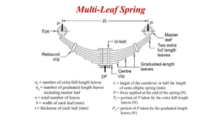
Multi-leaf springsare widely used for the suspension of cars, trucks
and railway wagons.
A multi-leaf spring consists of a series of flat plates, usually of semi-
elliptical shape. The flat plates are called leaves of the spring. The
leaves have graduated lengths. The leaf at the top has maximum
length. The length gradually decreases from the top leaf to the bottom
leaf. The longest leaf at the top is called master leaf. It is bent at both
ends to from the spring eyes.
Two bolts are inserted through these eyes to fix the leaf spring to the
automobile body. The leaves are held together by means of two U-
bolts and a centre clip. Rebound clips are provided to keep the leaves
in alignment and prevent lateral shifting of the leaves during
operation. At the centre, the leaf spring is supported on the axle.
Multi-leaf springs are provided with one or two extra full length
leaves in addition to master leaf. The extra full-length leaves are
stacked between the master leaf and the graduated length leaves. The
extra full-length leaves are provided to support the transverse shear
force.
117.
For thepurpose of analysis, the leaves are divided into two groups
namely, master leaf along with graduated-length leaves forming one
group and extra full-length leaves forming the other.
Multi-leaf springs are designed using load-stress and load-deflection
equations.
The standard dimensions for the width and thickness of the
leaf section are as follows:
Nominal thickness (mm): 3.2, 4.5, 5, 6, 6.5, 7, 7.5, 8, 9, 10, 11,
12, 14, and 16
Nominal width (mm): 32, 40, 45, 50, 55, 60, 65, 70, 75, 80, 90,
100 and 125
The leaves are usually made of steels, 55Si2Mn90, 50Cr1
or 50CrlV23. The plates are hardened and tempered.
The factor of safety based on the yield strength is from 2 to 2.5 for
the automobile suspension.
118.
Nipping of LeafSprings
In general, the stresses in extra full-length leaves are 50% more
than the stresses in graduated-length leaves. One of the
methods of equalising the stresses in different leaves is to pre-
stress the spring.
The pre-stressing is achieved by bending the leaves to different
radii of curvature, before they are assembled with the centre
clip. The full-length leaf is given a greater radius of curvature
than the adjacent leaf. The radius of curvature decreases with
shorter leaves.
The initial gap C between the extra full-length leaf and the
graduated-length leaf before the assembly, is called a ‘nip’.
Such pre-stressing, achieved by a difference in radii of
curvature, is known as ‘nipping’. Nipping is common in
automobile suspension springs.
119.
The initial pre-loadPi required to close the gap C between the extra
full-length leaves and graduated length leaves