Download to read offline
![International Research Journal of Engineering and Technology (IRJET) e-ISSN: 2395-0056
Volume: 07 Issue: 07 | July 2020 www.irjet.net p-ISSN: 2395-0072
© 2020, IRJET | Impact Factor value: 7.529 | ISO 9001:2008 Certified Journal | Page 3586
Comparative Investigation of 7-level Cascaded Multilevel Inverter
using Multicarrier Level Shifted PWM Techniques
Priyanka Meena1, Kapil Kansal2, Dr. Ahmed Hasan Khan3, Anil Kumar Sharma4
1Mtech Scholar, JIT Jaipur
2Asst. Professor, JIT Jaipur
3Professor, JIT Jaipur
4Asst. Professor, JIT Jaipur
1-4Dept. of electrical Engineering, Jaipur Institute of Technology and Group of Institutions, Jaipur, Rajasthan, India
----------------------------------------------------------------------***---------------------------------------------------------------------
Abstract - This manuscript presents the achieved efforts
on 1-ϕ 7-level cascaded H-bridge multilevel inverter. To
cheer the quality of 7-level CHBMLI output parameters
primarily THD and switching losses, multicarrier level
shifted technique is consider forcontrollingthegatepulse of
7level CHBMLI and the complete analysis of THD for 7-level
is done. This work is performed and results are validated
using MATLAB/SIMULINK.
Keywords: Multilevel Inverter (MLI), Cascaded H-Bridge
(CHBMLI), Multicarrier pulse width modulation technique
(MCPWM).
MULTILEVEL INVERTER:
An inverter is a tool that transfers DC to AC, with the use of
transformers the rehabilitated AC can be used at any
necessary voltages and frequencies. The inverters which
have no moving parts are static inverters and are employed
in various applications. Industries are now demanding
equipments with high powers, of the ranges of megawatt
level. Nowadays, it is tough to fix a sole power
semiconductor switch directly to medium voltagegrids(2.3,
3.3, 4.16, or 6.9 kV). So for higher level of voltage, a new
family of MLI has materializedasthewayoutforfunctioning.
MLI comprise an array of power semiconductors and
capacitor voltage sources, the output of which generate
voltages with stepped waveforms. Fig.1 shows a schematic
diagram of one phase leg of inverterswithdifferent numbers
of levels.[12, 13, 15]
Fig 1: One leg inverters (a) 1-level (b) 2-level (c) n-level
Classification of Multilevel Inverter:
(a) Diode clamped multilevel inverter (DC MLI)
A 3-phase 6-level DCMLI is given away in Fig 2 Each of the
three phases of the inverter shares a common DC bus, which
has been subdivided by five capacitors into six levels. The
voltage across each capacitor is Vdc, and the voltage stress
across each switching device is limited to Vdc through the
clamping diodes. This engages the (n-1) main DC link
capacitors and also Σ(2n-2) clamping diodes, where, n is the
number of levels [9, 11].
Fig 2: Structure of Three Phase Six Level DCMLI
Fig 3: Line Voltage Waveform of Six-Level DCMLI](https://image.slidesharecdn.com/irjet-v7i7628-201224054004/75/IRJET-Comparative-Investigation-of-7-level-Cascaded-Multilevel-Inverter-using-Multicarrier-Level-Shifted-PWM-Techniques-1-2048.jpg)
![International Research Journal of Engineering and Technology (IRJET) e-ISSN: 2395-0056
Volume: 07 Issue: 07 | July 2020 www.irjet.net p-ISSN: 2395-0072
© 2020, IRJET | Impact Factor value: 7.529 | ISO 9001:2008 Certified Journal | Page 3587
Advantages and Disadvantages of DCMLI.
(1) Advantages:
All of the phases share a common dc bus, which
minimizes the capacitance requirements of the
converter.
The capacitors can be pre charged as a group.
Effectiveness is elevated for elementary switching
of frequency.
(2) Disadvantages:
Real power flow is difficult for a single inverter
because the intermediate dc levels will tend to
overcharge or discharge without precise
monitoring and control.
The number of clamping diodes required is
quadratically related to the number oflevelswhich
can be cumbersome for units witha highnumberof
levels.
(b) FLYING CAPACITOR BASED MULTILEVEL
INVERTER(FCMLI)
The FCMLI necessitate a big number of capacitors to clamp
the device voltage to one capacitor voltage level provided all
the capacitors are equal value. An n-level inverter will
necessitate a total number of (n-1)*(n-2)/2 clamping
capacitors per phase. Fig 4 demonstratesthe3-phase6-level
FCMLI [10].
Fig 4: Structure of Three Phase Six-Level Flying Capacitor
Inverter.
Fig 5: Line Voltage Waveform of FCMLI Based.
Advantages and Disadvantages of FCMLI
(1) Advantages:
Additional clamping diodes are not required.
It has switching idleness inside the phase, which
can be used to balance the flying capacitors so that
only one DC source is desirable.
The requisite number of level of voltage can be
attained with no use of the transformer. This aid in
dropping the charge of the inverter and yet again
diminish loss of power.
(2) Disadvantages
Inverter initialization i.e., previous to the converter
can be adapted by any modulation method the
capacitors ought to bearrangedwiththeobligatory
voltage level as the preliminary charge.Thismakes
difficult the modulation procedure and turn out to
be an obstacle to the procedure of the converter.
Organizing is difficult to footpath the level of
voltage for every capacitor.
Pre charging every capacitor to identical level of
voltage and bring into being is difficult.
(c) CASCADED MULTILEVEL INVERTER(CHBMLI)
Fig. 6 deprived the basic layout of CHBMLI for single phase.
Every splitting voltage source (Vdc1, Vdc2, Vdc3) associated in
cascade through additional supply via a unique H-bridge
circuit linked through it. Every circuitcontainsfourswitches
that can create the voltage output source in positive or
negative polarity; or it can be simplyzerovoltsdepending on
the switching condition of the switches in the circuit [1, 2].
The level of output can be given by
2 1levelN S (1)
Where, S is the H-bridge
The voltage at every phase can be calculated by
𝑉𝑠𝑖 = 1 𝑉 𝑑𝑐 ( 𝑖 = 1,2,3 … ) (2)
The number of switches used in this topology is given by the
equation,
𝑁𝑠𝑤𝑖𝑡𝑐ℎ = 4𝑆 (3)
The rewards of the CHBMLI are series H-bridges for
modularized outline and wrapping. The Fig 7 demonstrates
the waveform of voltage output for a 7-level CHBMLI [7, 8].](https://image.slidesharecdn.com/irjet-v7i7628-201224054004/75/IRJET-Comparative-Investigation-of-7-level-Cascaded-Multilevel-Inverter-using-Multicarrier-Level-Shifted-PWM-Techniques-2-2048.jpg)
![International Research Journal of Engineering and Technology (IRJET) e-ISSN: 2395-0056
Volume: 07 Issue: 07 | July 2020 www.irjet.net p-ISSN: 2395-0072
© 2020, IRJET | Impact Factor value: 7.529 | ISO 9001:2008 Certified Journal | Page 3588
Fig 6: Topology for CHBMLI
Fig 7: Typical Output Waveform for CHBMLI
Advantages and Disadvantages of CHBMLI.
(1) Advantages
Very simple to regulate DC busses.
Modularity of control can be achieved.
Involve the slightest number of apparatus amongst
all MLI to attain the similar number of levels.
Flexible switching can be used in this arrangement
to keep away from hefty and lossy resistor
capacitor diode snubbers.
(2) Disadvantages
Communication between the bridges is essential to
accomplish the harmonization of referenceandthe
carrier waveforms.
Requires splited DC sources for real power
conversions, and therefore its purposes are a bit
inadequate.
MODULATION TECHNIQUES: ModulationTechnique
is Low and High switching Frequency fort high switching
frequency is considered above 1 KHz [13].
Multicarrier PWM: Multicarrier Pulse Width Modulation
Technique is used in three level or more than three levels.
These are classified into two types: - Level Shift, Phase Shift.
Level / Vertically Shifted PWM: Level shifted technique is
the reasonable addition of sine triangle PWM for MLI, in
which n-1 carriers are required for n-level inverter.They are
approved in vertical shifts in constant bands defined by the
levels of the inverter [8]. 3(n-1) carriers are requisite for 3-
phases. Based on managed degrees of liberty grouping, the
level shifted PWM is divided into PD, APOD and POD PWM
techniques [3, 5, 6].
Fig 8: Types of PWM control techniques
Phase Disposition Pulse Width Modulation (PD PWM):
The PDPWM with single reference is basedontheevaluation
of a sinusoidal reference signal with n-1 carriers which are
vertically shifted. From Fig 11 it can be known that the
carriers that have the similar frequency fc and amplitude Ac
are in phase. The modulating signal has a frequency of fr and
an amplitude Ar.
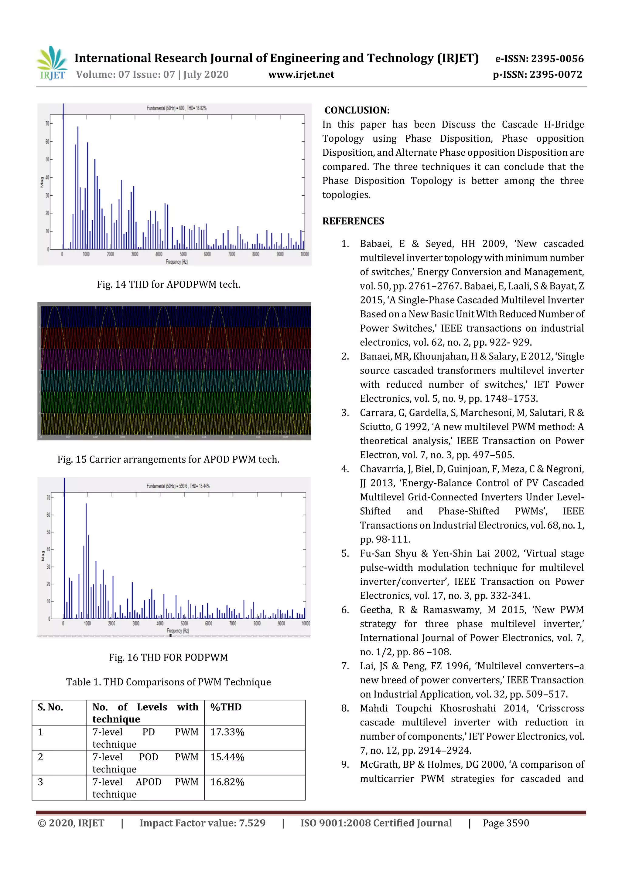
Alternate Phase Opposition Disposition Pulse Width
Modulation (APOD PWM): In APODPWM, the contiguous
carriers with identical frequency and amplitude are
positioned and overlapped and are phase displaced by 180o
in a mode as exposed in Fig 13. These carriers are evaluated
with single sinusoidal reference wave for the appropriate
procedure of CHBMLI.
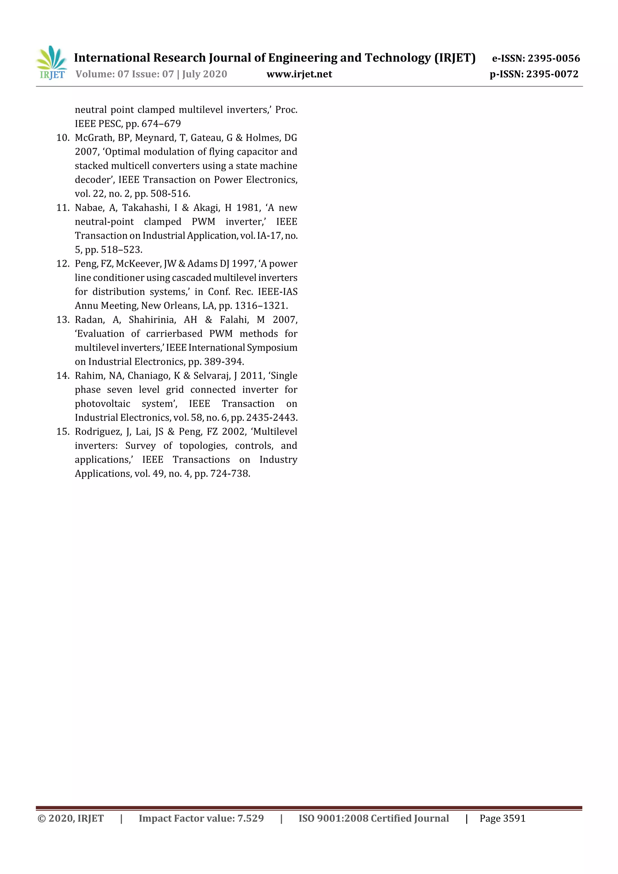
Phase Opposition Disposition Pulse Width Modulation
(POD PWM): The carrier signal with similar amplitude and
frequency are in phase over and under the zero reference
value. However, as exposed in Fig 15, there is 180o phase](https://image.slidesharecdn.com/irjet-v7i7628-201224054004/75/IRJET-Comparative-Investigation-of-7-level-Cascaded-Multilevel-Inverter-using-Multicarrier-Level-Shifted-PWM-Techniques-3-2048.jpg)
![International Research Journal of Engineering and Technology (IRJET) e-ISSN: 2395-0056
Volume: 07 Issue: 07 | July 2020 www.irjet.net p-ISSN: 2395-0072
© 2020, IRJET | Impact Factor value: 7.529 | ISO 9001:2008 Certified Journal | Page 3589
shift flanked by the ones over and under the zero reference.
These carriers are overlay with single reference signal to
produce the pulses for calculating the switches of MLI.
3. SIMULATION AND RESULTS:
Simulation of Seven Level CHBMLI: 7-level inverter is
simulated similar to that of the 5-level inverter. The
difference here is the number of carrier signals. Here six
carrier signals are employed. Three of them are applied
across the positive half cycle of the modulating signal [14].
Remaining three of them are applied acrossthenegativehalf
cycle of the modulating signal. From these signals twelve
PWM signals are generated and then given to the eight
switches of a leg. Pulses are generated for remainingphases.
Here the pulses were generated using various level shifting
techniques like PDPWM, PODPWM, APODPWM.
Fig. 9: Simulation for 7-level CHBMLI with PWM
technique.
5.3.1 Simulation Results:
Fig. 10 Output waveform for 7-level CHBMLI.
Fig. 11 Carrier arrangements for PD PWM
Fig.12 THD for PDPWM technique.
Fig. 13 Carrier arrangements for APOD PWM](https://image.slidesharecdn.com/irjet-v7i7628-201224054004/75/IRJET-Comparative-Investigation-of-7-level-Cascaded-Multilevel-Inverter-using-Multicarrier-Level-Shifted-PWM-Techniques-4-2048.jpg)

This document presents a comparative investigation of a 7-level cascaded multilevel inverter using different multicarrier pulse width modulation techniques. It discusses the classification, operation, and modulation strategies of multilevel inverters including diode clamped, flying capacitor, and cascaded H-bridge topologies. Simulation results in MATLAB/Simulink are presented to analyze the total harmonic distortion for a 7-level cascaded H-bridge multilevel inverter using phase disposition, alternate phase opposition disposition, and phase opposition disposition pulse width modulation techniques. The research aims to improve the output waveform quality and reduce switching losses of the 7-level inverter.