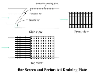
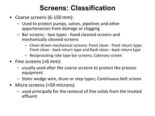
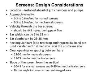
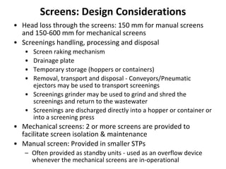
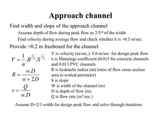
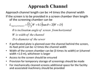
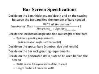
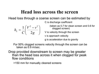
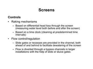
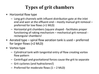
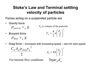
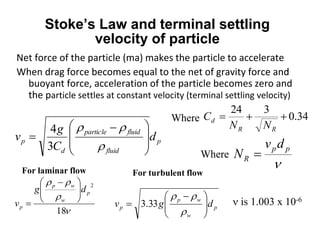
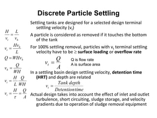
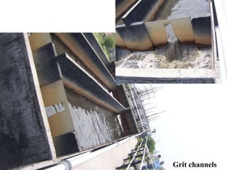
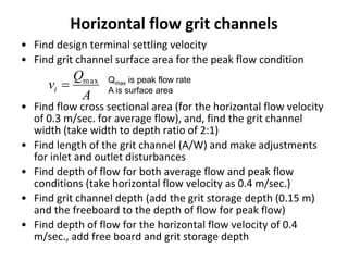
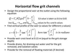
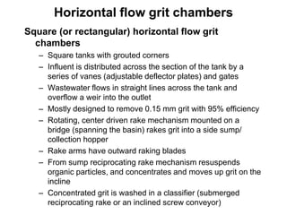
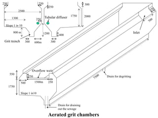
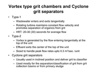
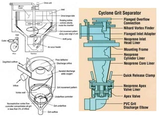
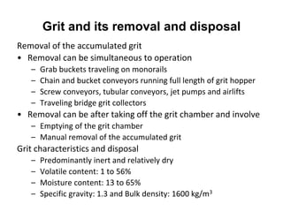
Preliminary Treatment Units
Dr. Akepati S. Reddy
School of Energy and Environment
Thapar University, Patiala
Bar Screens
Screens
• First unit usually encountered in the STP
• Important to avoid damage to subsequent process equipment
and increase overall treatment reliability & effectiveness
• Provided on channels carrying the sewage and include
– A bar rack
– Bar raking (cleaning) facility
– A perforated plate
– Temporary storage provision for the screenings
• Often housed in a screening chamber (if provided on an under
ground sewer)
– Access to the screen
– Length of the chamber should be sufficient
• to accommodate the screen and the perforated plate
• to facilitate cleaning of the approach channel
– Width of the chamber should include
• landing and working space for the worker
• Space for temporary storage of the screenings
Screens
Approach channel:
– Should have a straight approach
– Grit and heavy materials should not accumulate either
ahead of or following the screen during use
Bar screen/bar rack (a screen with parallel bars/rods)
– Bars: thickness, depth and length
– Spacing between bars and spacer bars
• 25-50 mm (for manual screens) and 15-75 mm (for
mechanical screens)
– Spacer bar: located behind (and perpendicular to bars) out
of the way of the lines of the rake and welded to the bars
– Angle of inclination of the screen: 30-45 from the vertical
for manual screens and 0-30 for mechanical screens
Perforated drainage plate is provided at the top of bar rack
for temporary storage and drainage of rakings
Even when flooded the sewage should pass to the other side
only through the bar screen
Front view
Top view
Bar Screen and Perforated Draining Plate
Side view
Spacing bar
Parallel bar
Perforated draining plate
Screens: Classification
• Coarse screens (6-150 mm):
– Used to protect pumps, valves, pipelines and other
appurtenances from damage or clogging
– Bar screens - two types - hand cleaned screens and
mechanically cleaned screens
– Chain driven mechanical screens: Front clean - front return type;
Front clean - back return type and Back clean - back return type
– Reciprocating rake type bar screens; Catenary screen
• Fine screens (<6 mm):
– usually used after the coarse screens to protect the process
equipment
– Static wedge wire, drum or step types; Continuous belt screen
• Micro screens (<50 microns)
– used principally for the removal of fine solids from the treated
effluent
Screens: Design Considerations
• Location - installed ahead of grit chambers and pumps
• Approach velocity:
– 0.3 to 0.6 m/sec for manual screens
– 0.3 to 1.0 m/sec for mechanical screens
• Velocity through the bar screen:
– should be <0.9 m/sec. during peak flow
• Bar width: can be 5 to 15 mm
• Bar depth: can be 25-38 mm
• Rectangular bars (also teardrop and trapezoidal bars) are
used - Wider width dimension is on the upstream side
• Clear openings or spacing between bars
– 25-50 mm for manual screens
– 15-75 mm for mechanical screens
• Slope of the screen from the vertical:
– 30-45 for manual screens and 0-30 for mechanical screens
– Flatter angle increases screen submerged area
Screens: Design Considerations
• Head loss through the screens: 150 mm for manual screens
and 150-600 mm for mechanical screens
• Screenings handling, processing and disposal
• Screen raking mechanism
• Drainage plate
• Temporary storage (hoppers or containers)
• Removal, transport and disposal - Conveyors/Pneumatic
ejectors may be used to transport screenings
• Screenings grinder may be used to grind and shred the
screenings and return to the wastewater
• Screenings are discharged directly into a hopper or container or
into a screening press
• Mechanical screens: 2 or more screens are provided to
facilitate screen isolation & maintenance
• Manual screen: Provided in smaller STPs
– Often provided as standby units - used as an overflow device
whenever the mechanical screens are in-operational
Approach channel
Find width and slope of the approach channel
Assume depth of flow during peak flow as 2/3rd of the width
Find velocity during average flow and check whether it is >0.3 m/sec.
Provide >0.2 m freeboard for the channel
2
1
3
2
..
1
SR
n
V 
V is velocity (m/sec.): 0.6 m/sec. for design peak flow
n is Mannings coefficient (0.015 for concrete channels
and 0.013 PVC channels
R is hydraulic radius (m) (ratio of flow cross section
area to wetted perimeter)
S is slope
W is width of the channel (m)
D is depth of flow (m)
Q is flow rate (m3/sec.)Dw
Q
v
Dw
Dw
R
.
2
.



Assume D=2/3 width for design peak flow and solve through iterations
Approach Channel
Approach channel length can be >4 times the channel width
If the screen is to be provided in a screen chamber then length
of the screening chamber can be
• If perforated plate is planned over the channel behind the screen,
its foot print can be >2 times the channel width
• Width of the screen chamber can be (3 times its width) or (channel
width +1.0 m), whichever is larger
• Access to the screen should be ensured
• Provision for temporary storage of screenings should be made
• For mechanically cleaned screens additional space for the facility
and associated machinery should be provided
   
sewertheofdiameterisD
channeltheofwidthisW
horizontalfromscreenofangleninclinatiois
DWWL channelApproach

  2tan3.0
3
2
Bar Screen Specifications
Decide on the bars thickness and depth and on the spacing
between the bars and find the number of bars needed
Decide the inclination angle and find out length of the bars
– D/sin(ө) + grouting requirements
(ө is inclination angle from horizontal)
Decide on the spacer bars (number, size and length)
Decide on the bar rack grouting requirements
Decide on the perforated drain plate to be used behind the
screen
– Width can be 0.2m plus width of the channel
– Length can be > 2 times the width
1


barsbetweenbar SpacingThickness
channeltheofWidth
BarsofNumber
Head loss across the screen
Head loss through a coarse screen can be estimated by
For 50% clogged screens velocity through the screen can be
taken as 0.9 m/sec.
Drop provided downstream to screen may be greater
than the head loss across it when clogged for peak
flow conditions
>150 mm for manually cleaned screens





 

g
vV
C
hL
2
1 22
C is discharge coefficient
(taken as 0.7 for clean screen and 0.6 for
clogged screen)
V is velocity through the screen
v is approach velocity
g is acceleration due to gravity
Screens
Controls
• Raking mechanisms
– Based on differential head loss through the screen
(measuring water level both before and after the screen)
– Based on a time clock (cleaning at predetermined time
intervals)
• Flow control/regulation
– Slide gates or recesses are provided in the channel, both
ahead of and behind to facilitate dewatering of the screen
– Flow is diverted through a bypass channels in larger
installations with the help of slide or sluice gates
Screens
Reciprocating rake type bar screens
• Rake moves to the base of the screen, engages the bars
and pulls screenings to the top of the screen for removal
• All parts requiring maintenance are above the water line
and can be easily inspected and maintained
• Front clean and front return feature minimizes solids carry
over
• Have only one rake and hence have limited capacity to
handle heavy screenings loads
• High overhead clearance is required to accommodate the
rake mechanism
• Grit accumulation in front of the bar can impede rake
movement
Screens
Catenary screen
• A type of front cleaned and front return chain driven
screen, but has no submerged sprockets
• Rake is held against the bar rack by weight of the chain
(less sensitive to bar jamming by heavy objects)
• Multiple cleaning elements, shorter cleaning cycles enable
handling of large objects (very little screenings carryover)
• Chains are very heavy, inclination angle of the screen is
higher (43 to 75) and hence large footprint
• Jammed racks can cause misalignment and warpage
• Open design can cause odors problem
Screens
Continuous belt screen
• It is a continuous self-cleaning screening belt that
removes fine and coarse solids
• Overhauling or replacement of the screening
elements is time consuming and expensive.
• Screen openings may range from 0.5 to 30 mm and
hence be used as either as a coarse screen or as a
fine screen
• Have no submerged sprockets
Grit Separators
Grit removal facilities
Located after bar screens, ahead of wastewater sump and
pumps – provided to
– Protect moving mechanical equipment from abrasion and
abnormal wear (pumps, valves, etc.)
– Reduce formation of heavy deposits in tanks, basins, pipelines,
channels, etc.
– Reduce frequency of cleaning of digesters
Designed for the removal of grit particles of size 0.15 (100 mesh)
or 0.21 mm (65 mesh) and specific gravity >2.65
– Sand, gravel, cinders, and other heavy solid particles having high
specific gravity and settling velocities (> organic solids)
Types of grit chambers
• Horizontal flow type
– Long grit channels with influent distribution gate at the inlet
end and weir at the effluent end – mostly manual grit removal –
preferred for low flows (<1 MLD)
– Horizontal grit chambers (square shaped - facilitates proper
functioning of raking mechanism – mechanical grit removal -
rectangular chambers!
• Aerated type – spiral flow aeration tank is used – preferred
for larger flows (>2 MLD)
• Vortex type
– Cylindrical tank with tangential entry of flow creating vortex
flow pattern
– Centrifugal and gravitational forces cause the grit to separate
– Grit cyclones (and hydroclones!)
– Preferred for moderate flows (1 – 2 MLD)
Stoke’s Law and Terminal settling
velocity of particles
Forces acting on a suspended particle are
• Gravity force
• Buoyant force
• Drag force – Increases with increasing speed – zero for zero speed
gpparticle 
gpfluid 
2
2
pfluidpd vAC 
ppdv3For laminar flow conditions
Vp is volume of the partcicle
2
3
2
4
23
4














p
p
p
p
d
A
d
V


Stoke’s Law and terminal settling
velocity of particle
Net force of the particle (ma) makes the particle to accelerate
When drag force becomes equal to the net of gravity force and
buoyant force, acceleration of the particle becomes zero and
the particle settles at constant velocity (terminal settling velocity)
p
fluid
fluidparticle
d
p d
C
g
v







 



3
4
34.0
324

RR
d
NN
C

pp
R
dv
N 
Where
Where



18
2
p
w
wp
p
dg
v





 

For laminar flow
p
w
wp
p dgv 




 



33.3
For turbulent flow
 is 1.003 x 10⁻⁶
Discrete Particle Settling
Settling tanks are designed for a selected design terminal
settling velocity (vt)
A particle is considered as removed if it touches the bottom
of the tank
For 100% settling removal, particles with vt terminal settling
velocity have to be  surface loading or overflow rate
In a settling basin design settling velocity, detention time
(HRT) and depth are related
Actual design takes into account the effect of inlet and outlet
turbulence, short circuiting, sludge storage, and velocity
gradients due to operation of sludge removal equipment
A
Q
vt 
timeDetention
depthTank
vt 
Q is flow rate
A is surface area
A
QH
v
WH
Q
L
H
v
WH
Q
v
WHvQ
L
Hv
v
v
L
v
H
t
t
h
h
h
t
ht







A
Q
vt 
Indicates grit removal efficiency is independent of depth and
detention time of the channel/chamber
Depth can be reduced – scouring problem is a limitation –
horizontal flow velocity should be <0.4 m/sec.
Increase of depth or width of channel reduces horizontal
flow velocity and results in settling of organics





 


p
s
f
Kgd
V
8
‘k’ depends on the material being scoured
(0.04 for unigranular particles and 0.06 for
sticky interlocked matter)
‘ρp and ρ’ are densities of particles and liquid
‘d’ is particle diameter
f is Darcy-Weisbach friction factor
(influenced by surface roughness and
Reynolds number, etc. – typical values 0.02-
0.03)
Camp-Shields equation
for scour velocity
Discrete Particle Settling
Only a fraction of the particles with the terminal settling
velocity < design settling velocity are removed in the
settling tank
Discrete Particle Settling
td
tp
v
v
removedFraction 
 
 





 n
i
i
n
i
i
td
tpi
td
tp
td
n
n
v
v
dX
v
v
XremovedfractionTotal
1
1
vtp is terminal settling velocity
vtd is design terminal settling velocity
Xtd is fraction with terminal settling velocity >vtd
dX is the fraction of grit with vtp
ni is the fraction of grit falling in the ith category
Horizontal flow grit channels
• Representative design data
– Horizontal flow velocity: 0.25 – 0.4 m/sec. (0.3)
– Head loss: 30-40% of channel depth (36%)
– Added length for inlet and outlet turbulence allowance: 25-50%
of actual length (30%)
• At the design horizontal flow velocity heavier grit particles
settle while the organic particles tend to get resuspended
• Flow control section at the outlet
– Parabolic channel cross section is ideal if parshall flume is used
– Rectangular channel cross section is ideal if proportional weir
(sutro weir) is used
• Has isolating gate valves at the inlet
• Has provisions for draining out the wastewater and manually
removing the accumulated grit
• Floating oil separation is often integrated
  













3
2
2
3
2
97.4
5.0
5.0
a
hgabCQ
a
hbaQ
d














 
5.0
1
tan
2
1
a
y
bx

.max
.max
.min
5.0
.max
.min5.1
.max
.max
262.0
H
Q
Q
a
Q
Q
gH
Q
b








Cd value is 0.6 to 0.65
b is taken as ‘channel width – 150 mm’!
Proportional weir (Sutro weir)
Grit channels
Horizontal flow grit channels
• Find design terminal settling velocity
• Find grit channel surface area for the peak flow condition
• Find flow cross sectional area (for the horizontal flow velocity
of 0.3 m/sec. for average flow), and, find the grit channel
width (take width to depth ratio of 2:1)
• Find length of the grit channel (A/W) and make adjustments
for inlet and outlet disturbances
• Find depth of flow for both average flow and peak flow
conditions (take horizontal flow velocity as 0.4 m/sec.)
• Find grit channel depth (add the grit storage depth (0.15 m)
and the freeboard to the depth of flow for peak flow)
• Find depth of flow for the horizontal flow velocity of 0.4
m/sec., add free board and grit storage depth
A
Q
vt
max
 Qmax is peak flow rate
A is surface area
Horizontal flow grit channels
• Design the proportional weir at the outlet using the following
equation
Use Qmax – hmax and Qavrg – havrg values to fix a and b values
• Find vertical profile of the weir (x values for different y values)
• Provide weir crest level at 0.15 m (equal to the grit storage
depth)
• Provide drains, for draining out water and for the grit
removed, and isolation valves
• Provide for the removal of floating materials (if desired)
  






3
2
5.0 a
hgabCQ d Cd value is taken as 0.6 to 0.65














 
5.0
1
tan
2
1
a
y
bx

radiansinis
a
y
here
5.0
1
tan 





Square (or rectangular) horizontal flow grit
chambers
– Square tanks with grouted corners
– Influent is distributed across the section of the tank by a
series of vanes (adjustable deflector plates) and gates
– Wastewater flows in straight lines across the tank and
overflow a weir into the outlet
– Mostly designed to remove 0.15 mm grit with 95% efficiency
– Rotating, center driven rake mechanism mounted on a
bridge (spanning the basin) rakes grit into a side sump/
collection hopper
– Rake arms have outward raking blades
– From sump reciprocating rake mechanism resuspends
organic particles, and concentrates and moves up grit on the
incline
– Concentrated grit is washed in a classifier (submerged
reciprocating rake or an inclined screw conveyor)
Horizontal flow grit chambers
Grit separator-classifier
• Reciprocating rake mechanism is set in an inclined
concrete channel
– All drive components and bearings are located above the
liquid level and protected from corrosion
– Putrifiable organics are liberated and washed and a recycle
pump returns the organic matter into the degritted sewage
• Grit screw classifier: a tubular sheet shaft and helical flight
assembly set in a semicircular inclined concrete
trough/channel
• Cyclone separator with a reciprocating rake classifier: grit
from the collection basin is pumped through the cyclone
separator for concentrating and delivering the solids into
the hopper of the classifier for washing and discharge
Grit Collector and Classifier
Cyclone Grit Separator and Classifier
Aerated grit chambers
• Rectangular tank with aeration by coarse bubble diffusers
along one side creats spiral flow perpendicular to the flow
– Velocity of roll governs size & SG of the particles setting
– Strategically positioned longitudinal circulation baffle directs
the rotational flow and a vertical baffle at the far end
prevents flow short-circuiting
– Wastewater is introduced in the direction of the roll
– Wastewater makes 2-3 turns at peak flow
• Grit hopper: Located along one side of the tank, 0.9 m
deep, has steep sloping sides
• Design information
– Designed for 0.21 mm grit particles removal
– HRT is 2 to 5 minutes at peak hourly flow
– Air diffusers: Located 0.45-0.6 m above the normal plane
– Width to depth ratio: 1:1 to 5:1 (1.5:1)
– Length to width ratio: 3:1 to 5:1 (4:1)
– Air supply: 0.2 to 0.5 m3/m.min.
• Expansion by air should be considered in head loss
estimation
2000
2500
800 m
Slope 1 in 10
1200
300600m
400
300
300250250
1300
Aerated grit chambers
550
1750
250
2501500m
Slope 1 in10
1750
250
500
Tubular diffuser
Overflow weir
Grit trench
Inlet
250
Drain for degritting
Drain for draining
out the sewage
Vortex type grit chambers and Cyclone
grit separators
• Type-1
– Wastewater enters and exits tangentially
– Rotating turbine maintains constant flow velocity and
promotes separation of organics from grit
– HRT: 20-30 (30) seconds for average flow
• Type-2
– Vortex is generated by the flow entering tangentially at the
top of the unit
– Effluent exits the center of the top of the unit
– Sized to handle peak flow rates upto 0.3 m3/sec. /unit
• Cyclone grit separators
– Usually used in inclined position and deliver grit to classifier
– Used mostly for the separation/classification of grit from grit
collection basins or from primary sludge
Grit and its removal and disposal
Removal of the accumulated grit
• Removal can be simultaneous to operation
– Grab buckets traveling on monorails
– Chain and bucket conveyors running full length of grit hopper
– Screw conveyors, tubular conveyors, jet pumps and airlifts
– Traveling bridge grit collectors
• Removal can be after taking off the grit chamber and involve
– Emptying of the grit chamber
– Manual removal of the accumulated grit
Grit characteristics and disposal
– Predominantly inert and relatively dry
– Volatile content: 1 to 56%
– Moisture content: 13 to 65%
– Specific gravity: 1.3 and Bulk density: 1600 kg/m3
• If no grit chambers provided and if grit accumulates in the
primary sludge then for removal
– diluted primary sludge is passed through cyclone degritter
• Grit separators and grit washers are used to remove organics
– Water sprays in both cases help in grit washing
– Inclined submerged rake - necessary agitation is provided for
organics removal while the grit is raised on incline to discharge
point
– Inclined screw – lifts the grit up the ramp
• Grit disposal
– Transport to landfill and stabilize with lime prior to landfilling (!)
– Incinerate the grit with other solids
– Pneumatic conveyors for conveying grit over short distances
Grit and its removal and disposal
Equalization
Flow Equalization
Damping of variations in wastewater flow rates and
strength (BOD, etc.) - may be needed to
• overcome operational problems
• improve performance of the down stream processes –
reduced peak flows and shock loads, and diluted inhibitory
substances – for biological treatment
• reduce size and cost of downstream treatment facilities
Disadvantages of equalization:
• Increased capital costs and land requirement
• Additional operation and maintenance requirement
• Odours problem
Equalization types:
• Inline equalization: All flow passes through equalization tank
– Better for achieving constituent concentration damping
• Off line equalization: only flow above the predetermined limit
is diverted into equalization tank
– Pumping requirements are minimized
Design Considerations
Where to locate an equalization facility? – Optimum
location varies with
– Characteristics of the collection system
– Wastewater to be handled
– Land requirements and availability
– Type of treatment required – some may not require
• In-line or off-line equalization which should be used?
• Equalization ahead of the primary settling: demands
mixing (and aeration) to prevent deposition of solids and
odour problems
• Equalization between the primary treatment and the
secondary treatment: can cause fewer problems with
solids deposition and scum accumulation
• Better grit removal facilities must precede the
equalization tanks
Design Considerations
Equalization tank volume
• Cumulative inflow diagram is used to find the volume
– Plot cumulative inflow against time of the day
– Connect starting and ending points by a straight line to obtain
cumulative average outflow plot
– Draw two tangents to the cumulative inflow plot (one above and
the other below), parallel to cumulative average outflow plot and
take vertical distance between the 2 tangents as the
equalization tank volume
– At the low point of the tangent, the basin will be empty, and at
the high point of the tangent, the tank will be full
• Cumulative net flow diagram can also be used
– Subtract average hourly outflow from the hourly inflow to get the
net flow
– Plot the cumulative net flow against time
– Take the vertical distance between the lowest and the high
points as the equalization tank volume
Equalization volume
Actual volume of the equalization tank is larger (by 10-20%)
• Continuous operation of aeration and mixing equipment do
not allow complete emptying of the basin
• Basin may also receive plant recycle streams
• Contingency is needed for taking care of unforeseen changes
in flow rates and flow variations – may require freeboard
Geometry of the equalization tank
• Depends on the available land area and on whether the
equalization is in-line or off-line
– Elongated designs are avoided
• Depth depends on land availability, groundwater level and
topography
• Free board depends on tank size and wind conditions
• Inlet and outlet are arranged to minimize short circuiting –
often multiple inlets and outlets are used
• For better access for cleaning, front end loaders and multiple
compartments are preferred
Design Considerations
Equalization tank/basin
Design considerations
Earthen basins, or concrete or steel tanks can be used
Access, cleaning and safety should be considered in the
design of equalization tanks
Operational appurtenances
– Facilities for flushing any solids and grease that may tend to
accumulate on basin walls
– High water takeoff for removing floating material and foam
– Water sprays to prevent accumulation and aid foam removal
– Separate odour control facilities (covered equalization basins!)
may also be needed
Pump and pump control system
– Pumping facilities are usually required either before or after the
equalization tank
• before is preferred for greater reliability
– Flow measurement devices and flow regulation devices may be
required on the outlet to monitor the equalized flow
Mixing and aeration requirements
• Required to blend the contents and prevent solids
deposition
• Floating aerators, if used, may need a minimum operating
level of 1.5 to 2 m of the tank
– A concrete pad below to minimize erosion may be needed in
earthen basins
• Power requirement for mixing may be in the range of 0.004 to 0.008
kW/m3 (when TSS is <210 mg/L)
– In case of mechanical aerators vortex formation should be
avoided (provide baffles in circular tanks!)
– The aerators may require low level shut off controls
– Aerators can be equipped with legs or draft tubes for resting on
• Aeration is required to prevent septic and odorous conditions
– Air requirements for aerobic conditions is 0.01-0.015 m3/m3.min
– Diffused aeration systems can be used for mixing and aeration
Design considerations
Impact of Flow Equalization on
Strength
Start at the point of time when the tank is at residual volume
Compute tank liquid volume at the end of each time period
– Volume already present in the tank at the beginning
– In-flowing during the period
– Out-flowing during the period
Compute average concentration in the tank
– Divide pollutant load (already present + added during the
period) with effluent volume (already present + added
during the period) - Instantaneous mixing is assumed here
Compute mass load of the pollutant during the period
Show the effect of equalization on pollution load to the ETP
– Graphically; or by ratios, such as, peak to average or to
minimum, minimum to average or to peak; or Stand. dev.
Impact of flow equalization on strength
Residual Volume and Strength
Equalization
• Residual volume is usually provided to protect the
aeration/mixing equipment provided
– If it increases strength equalization also increases
• Equalization tanks can also be designed for strength
equalization
– Find flow equalization volume
– Take different residual volumes and compute the level of
strength equalization achieved
– Choose the minimum residual volume at which the
required strength equalization is achieved
• Equalization basins can be designed for strength
equalization only but no flow equalization
– Liquid volume in the equalization basin is maintained
constant
– The inflow is almost balanced by the outflow - all the inflow
fluctuations are reflected in the outflows

02b priliminary treatment

  • 1.
    Preliminary Treatment Units Dr.Akepati S. Reddy School of Energy and Environment Thapar University, Patiala
  • 2.
  • 3.
    Screens • First unitusually encountered in the STP • Important to avoid damage to subsequent process equipment and increase overall treatment reliability & effectiveness • Provided on channels carrying the sewage and include – A bar rack – Bar raking (cleaning) facility – A perforated plate – Temporary storage provision for the screenings • Often housed in a screening chamber (if provided on an under ground sewer) – Access to the screen – Length of the chamber should be sufficient • to accommodate the screen and the perforated plate • to facilitate cleaning of the approach channel – Width of the chamber should include • landing and working space for the worker • Space for temporary storage of the screenings
  • 4.
    Screens Approach channel: – Shouldhave a straight approach – Grit and heavy materials should not accumulate either ahead of or following the screen during use Bar screen/bar rack (a screen with parallel bars/rods) – Bars: thickness, depth and length – Spacing between bars and spacer bars • 25-50 mm (for manual screens) and 15-75 mm (for mechanical screens) – Spacer bar: located behind (and perpendicular to bars) out of the way of the lines of the rake and welded to the bars – Angle of inclination of the screen: 30-45 from the vertical for manual screens and 0-30 for mechanical screens Perforated drainage plate is provided at the top of bar rack for temporary storage and drainage of rakings Even when flooded the sewage should pass to the other side only through the bar screen
  • 5.
    Front view Top view BarScreen and Perforated Draining Plate Side view Spacing bar Parallel bar Perforated draining plate
  • 6.
    Screens: Classification • Coarsescreens (6-150 mm): – Used to protect pumps, valves, pipelines and other appurtenances from damage or clogging – Bar screens - two types - hand cleaned screens and mechanically cleaned screens – Chain driven mechanical screens: Front clean - front return type; Front clean - back return type and Back clean - back return type – Reciprocating rake type bar screens; Catenary screen • Fine screens (<6 mm): – usually used after the coarse screens to protect the process equipment – Static wedge wire, drum or step types; Continuous belt screen • Micro screens (<50 microns) – used principally for the removal of fine solids from the treated effluent
  • 7.
    Screens: Design Considerations •Location - installed ahead of grit chambers and pumps • Approach velocity: – 0.3 to 0.6 m/sec for manual screens – 0.3 to 1.0 m/sec for mechanical screens • Velocity through the bar screen: – should be <0.9 m/sec. during peak flow • Bar width: can be 5 to 15 mm • Bar depth: can be 25-38 mm • Rectangular bars (also teardrop and trapezoidal bars) are used - Wider width dimension is on the upstream side • Clear openings or spacing between bars – 25-50 mm for manual screens – 15-75 mm for mechanical screens • Slope of the screen from the vertical: – 30-45 for manual screens and 0-30 for mechanical screens – Flatter angle increases screen submerged area
  • 8.
    Screens: Design Considerations •Head loss through the screens: 150 mm for manual screens and 150-600 mm for mechanical screens • Screenings handling, processing and disposal • Screen raking mechanism • Drainage plate • Temporary storage (hoppers or containers) • Removal, transport and disposal - Conveyors/Pneumatic ejectors may be used to transport screenings • Screenings grinder may be used to grind and shred the screenings and return to the wastewater • Screenings are discharged directly into a hopper or container or into a screening press • Mechanical screens: 2 or more screens are provided to facilitate screen isolation & maintenance • Manual screen: Provided in smaller STPs – Often provided as standby units - used as an overflow device whenever the mechanical screens are in-operational
  • 9.
    Approach channel Find widthand slope of the approach channel Assume depth of flow during peak flow as 2/3rd of the width Find velocity during average flow and check whether it is >0.3 m/sec. Provide >0.2 m freeboard for the channel 2 1 3 2 .. 1 SR n V  V is velocity (m/sec.): 0.6 m/sec. for design peak flow n is Mannings coefficient (0.015 for concrete channels and 0.013 PVC channels R is hydraulic radius (m) (ratio of flow cross section area to wetted perimeter) S is slope W is width of the channel (m) D is depth of flow (m) Q is flow rate (m3/sec.)Dw Q v Dw Dw R . 2 .    Assume D=2/3 width for design peak flow and solve through iterations
  • 10.
    Approach Channel Approach channellength can be >4 times the channel width If the screen is to be provided in a screen chamber then length of the screening chamber can be • If perforated plate is planned over the channel behind the screen, its foot print can be >2 times the channel width • Width of the screen chamber can be (3 times its width) or (channel width +1.0 m), whichever is larger • Access to the screen should be ensured • Provision for temporary storage of screenings should be made • For mechanically cleaned screens additional space for the facility and associated machinery should be provided     sewertheofdiameterisD channeltheofwidthisW horizontalfromscreenofangleninclinatiois DWWL channelApproach    2tan3.0 3 2
  • 11.
    Bar Screen Specifications Decideon the bars thickness and depth and on the spacing between the bars and find the number of bars needed Decide the inclination angle and find out length of the bars – D/sin(ө) + grouting requirements (ө is inclination angle from horizontal) Decide on the spacer bars (number, size and length) Decide on the bar rack grouting requirements Decide on the perforated drain plate to be used behind the screen – Width can be 0.2m plus width of the channel – Length can be > 2 times the width 1   barsbetweenbar SpacingThickness channeltheofWidth BarsofNumber
  • 12.
    Head loss acrossthe screen Head loss through a coarse screen can be estimated by For 50% clogged screens velocity through the screen can be taken as 0.9 m/sec. Drop provided downstream to screen may be greater than the head loss across it when clogged for peak flow conditions >150 mm for manually cleaned screens         g vV C hL 2 1 22 C is discharge coefficient (taken as 0.7 for clean screen and 0.6 for clogged screen) V is velocity through the screen v is approach velocity g is acceleration due to gravity
  • 13.
    Screens Controls • Raking mechanisms –Based on differential head loss through the screen (measuring water level both before and after the screen) – Based on a time clock (cleaning at predetermined time intervals) • Flow control/regulation – Slide gates or recesses are provided in the channel, both ahead of and behind to facilitate dewatering of the screen – Flow is diverted through a bypass channels in larger installations with the help of slide or sluice gates
  • 15.
    Screens Reciprocating rake typebar screens • Rake moves to the base of the screen, engages the bars and pulls screenings to the top of the screen for removal • All parts requiring maintenance are above the water line and can be easily inspected and maintained • Front clean and front return feature minimizes solids carry over • Have only one rake and hence have limited capacity to handle heavy screenings loads • High overhead clearance is required to accommodate the rake mechanism • Grit accumulation in front of the bar can impede rake movement
  • 17.
    Screens Catenary screen • Atype of front cleaned and front return chain driven screen, but has no submerged sprockets • Rake is held against the bar rack by weight of the chain (less sensitive to bar jamming by heavy objects) • Multiple cleaning elements, shorter cleaning cycles enable handling of large objects (very little screenings carryover) • Chains are very heavy, inclination angle of the screen is higher (43 to 75) and hence large footprint • Jammed racks can cause misalignment and warpage • Open design can cause odors problem
  • 18.
    Screens Continuous belt screen •It is a continuous self-cleaning screening belt that removes fine and coarse solids • Overhauling or replacement of the screening elements is time consuming and expensive. • Screen openings may range from 0.5 to 30 mm and hence be used as either as a coarse screen or as a fine screen • Have no submerged sprockets
  • 20.
  • 21.
    Grit removal facilities Locatedafter bar screens, ahead of wastewater sump and pumps – provided to – Protect moving mechanical equipment from abrasion and abnormal wear (pumps, valves, etc.) – Reduce formation of heavy deposits in tanks, basins, pipelines, channels, etc. – Reduce frequency of cleaning of digesters Designed for the removal of grit particles of size 0.15 (100 mesh) or 0.21 mm (65 mesh) and specific gravity >2.65 – Sand, gravel, cinders, and other heavy solid particles having high specific gravity and settling velocities (> organic solids)
  • 22.
    Types of gritchambers • Horizontal flow type – Long grit channels with influent distribution gate at the inlet end and weir at the effluent end – mostly manual grit removal – preferred for low flows (<1 MLD) – Horizontal grit chambers (square shaped - facilitates proper functioning of raking mechanism – mechanical grit removal - rectangular chambers! • Aerated type – spiral flow aeration tank is used – preferred for larger flows (>2 MLD) • Vortex type – Cylindrical tank with tangential entry of flow creating vortex flow pattern – Centrifugal and gravitational forces cause the grit to separate – Grit cyclones (and hydroclones!) – Preferred for moderate flows (1 – 2 MLD)
  • 23.
    Stoke’s Law andTerminal settling velocity of particles Forces acting on a suspended particle are • Gravity force • Buoyant force • Drag force – Increases with increasing speed – zero for zero speed gpparticle  gpfluid  2 2 pfluidpd vAC  ppdv3For laminar flow conditions Vp is volume of the partcicle 2 3 2 4 23 4               p p p p d A d V  
  • 24.
    Stoke’s Law andterminal settling velocity of particle Net force of the particle (ma) makes the particle to accelerate When drag force becomes equal to the net of gravity force and buoyant force, acceleration of the particle becomes zero and the particle settles at constant velocity (terminal settling velocity) p fluid fluidparticle d p d C g v             3 4 34.0 324  RR d NN C  pp R dv N  Where Where    18 2 p w wp p dg v         For laminar flow p w wp p dgv           33.3 For turbulent flow  is 1.003 x 10⁻⁶
  • 25.
    Discrete Particle Settling Settlingtanks are designed for a selected design terminal settling velocity (vt) A particle is considered as removed if it touches the bottom of the tank For 100% settling removal, particles with vt terminal settling velocity have to be  surface loading or overflow rate In a settling basin design settling velocity, detention time (HRT) and depth are related Actual design takes into account the effect of inlet and outlet turbulence, short circuiting, sludge storage, and velocity gradients due to operation of sludge removal equipment A Q vt  timeDetention depthTank vt  Q is flow rate A is surface area A QH v WH Q L H v WH Q v WHvQ L Hv v v L v H t t h h h t ht       
  • 26.
    A Q vt  Indicates gritremoval efficiency is independent of depth and detention time of the channel/chamber Depth can be reduced – scouring problem is a limitation – horizontal flow velocity should be <0.4 m/sec. Increase of depth or width of channel reduces horizontal flow velocity and results in settling of organics          p s f Kgd V 8 ‘k’ depends on the material being scoured (0.04 for unigranular particles and 0.06 for sticky interlocked matter) ‘ρp and ρ’ are densities of particles and liquid ‘d’ is particle diameter f is Darcy-Weisbach friction factor (influenced by surface roughness and Reynolds number, etc. – typical values 0.02- 0.03) Camp-Shields equation for scour velocity Discrete Particle Settling
  • 27.
    Only a fractionof the particles with the terminal settling velocity < design settling velocity are removed in the settling tank Discrete Particle Settling td tp v v removedFraction            n i i n i i td tpi td tp td n n v v dX v v XremovedfractionTotal 1 1 vtp is terminal settling velocity vtd is design terminal settling velocity Xtd is fraction with terminal settling velocity >vtd dX is the fraction of grit with vtp ni is the fraction of grit falling in the ith category
  • 28.
    Horizontal flow gritchannels • Representative design data – Horizontal flow velocity: 0.25 – 0.4 m/sec. (0.3) – Head loss: 30-40% of channel depth (36%) – Added length for inlet and outlet turbulence allowance: 25-50% of actual length (30%) • At the design horizontal flow velocity heavier grit particles settle while the organic particles tend to get resuspended • Flow control section at the outlet – Parabolic channel cross section is ideal if parshall flume is used – Rectangular channel cross section is ideal if proportional weir (sutro weir) is used • Has isolating gate valves at the inlet • Has provisions for draining out the wastewater and manually removing the accumulated grit • Floating oil separation is often integrated
  • 29.
                    3 2 2 3 2 97.4 5.0 5.0 a hgabCQ a hbaQ d                5.0 1 tan 2 1 a y bx  .max .max .min 5.0 .max .min5.1 .max .max 262.0 H Q Q a Q Q gH Q b         Cd value is 0.6 to 0.65 b is taken as ‘channel width – 150 mm’! Proportional weir (Sutro weir)
  • 30.
  • 31.
    Horizontal flow gritchannels • Find design terminal settling velocity • Find grit channel surface area for the peak flow condition • Find flow cross sectional area (for the horizontal flow velocity of 0.3 m/sec. for average flow), and, find the grit channel width (take width to depth ratio of 2:1) • Find length of the grit channel (A/W) and make adjustments for inlet and outlet disturbances • Find depth of flow for both average flow and peak flow conditions (take horizontal flow velocity as 0.4 m/sec.) • Find grit channel depth (add the grit storage depth (0.15 m) and the freeboard to the depth of flow for peak flow) • Find depth of flow for the horizontal flow velocity of 0.4 m/sec., add free board and grit storage depth A Q vt max  Qmax is peak flow rate A is surface area
  • 32.
    Horizontal flow gritchannels • Design the proportional weir at the outlet using the following equation Use Qmax – hmax and Qavrg – havrg values to fix a and b values • Find vertical profile of the weir (x values for different y values) • Provide weir crest level at 0.15 m (equal to the grit storage depth) • Provide drains, for draining out water and for the grit removed, and isolation valves • Provide for the removal of floating materials (if desired)          3 2 5.0 a hgabCQ d Cd value is taken as 0.6 to 0.65                 5.0 1 tan 2 1 a y bx  radiansinis a y here 5.0 1 tan      
  • 33.
    Square (or rectangular)horizontal flow grit chambers – Square tanks with grouted corners – Influent is distributed across the section of the tank by a series of vanes (adjustable deflector plates) and gates – Wastewater flows in straight lines across the tank and overflow a weir into the outlet – Mostly designed to remove 0.15 mm grit with 95% efficiency – Rotating, center driven rake mechanism mounted on a bridge (spanning the basin) rakes grit into a side sump/ collection hopper – Rake arms have outward raking blades – From sump reciprocating rake mechanism resuspends organic particles, and concentrates and moves up grit on the incline – Concentrated grit is washed in a classifier (submerged reciprocating rake or an inclined screw conveyor) Horizontal flow grit chambers
  • 34.
    Grit separator-classifier • Reciprocatingrake mechanism is set in an inclined concrete channel – All drive components and bearings are located above the liquid level and protected from corrosion – Putrifiable organics are liberated and washed and a recycle pump returns the organic matter into the degritted sewage • Grit screw classifier: a tubular sheet shaft and helical flight assembly set in a semicircular inclined concrete trough/channel • Cyclone separator with a reciprocating rake classifier: grit from the collection basin is pumped through the cyclone separator for concentrating and delivering the solids into the hopper of the classifier for washing and discharge
  • 35.
  • 36.
    Cyclone Grit Separatorand Classifier
  • 37.
    Aerated grit chambers •Rectangular tank with aeration by coarse bubble diffusers along one side creats spiral flow perpendicular to the flow – Velocity of roll governs size & SG of the particles setting – Strategically positioned longitudinal circulation baffle directs the rotational flow and a vertical baffle at the far end prevents flow short-circuiting – Wastewater is introduced in the direction of the roll – Wastewater makes 2-3 turns at peak flow • Grit hopper: Located along one side of the tank, 0.9 m deep, has steep sloping sides • Design information – Designed for 0.21 mm grit particles removal – HRT is 2 to 5 minutes at peak hourly flow – Air diffusers: Located 0.45-0.6 m above the normal plane – Width to depth ratio: 1:1 to 5:1 (1.5:1) – Length to width ratio: 3:1 to 5:1 (4:1) – Air supply: 0.2 to 0.5 m3/m.min. • Expansion by air should be considered in head loss estimation
  • 39.
    2000 2500 800 m Slope 1in 10 1200 300600m 400 300 300250250 1300 Aerated grit chambers 550 1750 250 2501500m Slope 1 in10 1750 250 500 Tubular diffuser Overflow weir Grit trench Inlet 250 Drain for degritting Drain for draining out the sewage
  • 40.
    Vortex type gritchambers and Cyclone grit separators • Type-1 – Wastewater enters and exits tangentially – Rotating turbine maintains constant flow velocity and promotes separation of organics from grit – HRT: 20-30 (30) seconds for average flow • Type-2 – Vortex is generated by the flow entering tangentially at the top of the unit – Effluent exits the center of the top of the unit – Sized to handle peak flow rates upto 0.3 m3/sec. /unit • Cyclone grit separators – Usually used in inclined position and deliver grit to classifier – Used mostly for the separation/classification of grit from grit collection basins or from primary sludge
  • 42.
    Grit and itsremoval and disposal Removal of the accumulated grit • Removal can be simultaneous to operation – Grab buckets traveling on monorails – Chain and bucket conveyors running full length of grit hopper – Screw conveyors, tubular conveyors, jet pumps and airlifts – Traveling bridge grit collectors • Removal can be after taking off the grit chamber and involve – Emptying of the grit chamber – Manual removal of the accumulated grit Grit characteristics and disposal – Predominantly inert and relatively dry – Volatile content: 1 to 56% – Moisture content: 13 to 65% – Specific gravity: 1.3 and Bulk density: 1600 kg/m3
  • 43.
    • If nogrit chambers provided and if grit accumulates in the primary sludge then for removal – diluted primary sludge is passed through cyclone degritter • Grit separators and grit washers are used to remove organics – Water sprays in both cases help in grit washing – Inclined submerged rake - necessary agitation is provided for organics removal while the grit is raised on incline to discharge point – Inclined screw – lifts the grit up the ramp • Grit disposal – Transport to landfill and stabilize with lime prior to landfilling (!) – Incinerate the grit with other solids – Pneumatic conveyors for conveying grit over short distances Grit and its removal and disposal
  • 44.
  • 45.
    Flow Equalization Damping ofvariations in wastewater flow rates and strength (BOD, etc.) - may be needed to • overcome operational problems • improve performance of the down stream processes – reduced peak flows and shock loads, and diluted inhibitory substances – for biological treatment • reduce size and cost of downstream treatment facilities Disadvantages of equalization: • Increased capital costs and land requirement • Additional operation and maintenance requirement • Odours problem Equalization types: • Inline equalization: All flow passes through equalization tank – Better for achieving constituent concentration damping • Off line equalization: only flow above the predetermined limit is diverted into equalization tank – Pumping requirements are minimized
  • 47.
    Design Considerations Where tolocate an equalization facility? – Optimum location varies with – Characteristics of the collection system – Wastewater to be handled – Land requirements and availability – Type of treatment required – some may not require • In-line or off-line equalization which should be used? • Equalization ahead of the primary settling: demands mixing (and aeration) to prevent deposition of solids and odour problems • Equalization between the primary treatment and the secondary treatment: can cause fewer problems with solids deposition and scum accumulation • Better grit removal facilities must precede the equalization tanks
  • 48.
    Design Considerations Equalization tankvolume • Cumulative inflow diagram is used to find the volume – Plot cumulative inflow against time of the day – Connect starting and ending points by a straight line to obtain cumulative average outflow plot – Draw two tangents to the cumulative inflow plot (one above and the other below), parallel to cumulative average outflow plot and take vertical distance between the 2 tangents as the equalization tank volume – At the low point of the tangent, the basin will be empty, and at the high point of the tangent, the tank will be full • Cumulative net flow diagram can also be used – Subtract average hourly outflow from the hourly inflow to get the net flow – Plot the cumulative net flow against time – Take the vertical distance between the lowest and the high points as the equalization tank volume
  • 49.
  • 50.
    Actual volume ofthe equalization tank is larger (by 10-20%) • Continuous operation of aeration and mixing equipment do not allow complete emptying of the basin • Basin may also receive plant recycle streams • Contingency is needed for taking care of unforeseen changes in flow rates and flow variations – may require freeboard Geometry of the equalization tank • Depends on the available land area and on whether the equalization is in-line or off-line – Elongated designs are avoided • Depth depends on land availability, groundwater level and topography • Free board depends on tank size and wind conditions • Inlet and outlet are arranged to minimize short circuiting – often multiple inlets and outlets are used • For better access for cleaning, front end loaders and multiple compartments are preferred Design Considerations
  • 51.
  • 52.
    Design considerations Earthen basins,or concrete or steel tanks can be used Access, cleaning and safety should be considered in the design of equalization tanks Operational appurtenances – Facilities for flushing any solids and grease that may tend to accumulate on basin walls – High water takeoff for removing floating material and foam – Water sprays to prevent accumulation and aid foam removal – Separate odour control facilities (covered equalization basins!) may also be needed Pump and pump control system – Pumping facilities are usually required either before or after the equalization tank • before is preferred for greater reliability – Flow measurement devices and flow regulation devices may be required on the outlet to monitor the equalized flow
  • 53.
    Mixing and aerationrequirements • Required to blend the contents and prevent solids deposition • Floating aerators, if used, may need a minimum operating level of 1.5 to 2 m of the tank – A concrete pad below to minimize erosion may be needed in earthen basins • Power requirement for mixing may be in the range of 0.004 to 0.008 kW/m3 (when TSS is <210 mg/L) – In case of mechanical aerators vortex formation should be avoided (provide baffles in circular tanks!) – The aerators may require low level shut off controls – Aerators can be equipped with legs or draft tubes for resting on • Aeration is required to prevent septic and odorous conditions – Air requirements for aerobic conditions is 0.01-0.015 m3/m3.min – Diffused aeration systems can be used for mixing and aeration Design considerations
  • 54.
    Impact of FlowEqualization on Strength Start at the point of time when the tank is at residual volume Compute tank liquid volume at the end of each time period – Volume already present in the tank at the beginning – In-flowing during the period – Out-flowing during the period Compute average concentration in the tank – Divide pollutant load (already present + added during the period) with effluent volume (already present + added during the period) - Instantaneous mixing is assumed here Compute mass load of the pollutant during the period Show the effect of equalization on pollution load to the ETP – Graphically; or by ratios, such as, peak to average or to minimum, minimum to average or to peak; or Stand. dev.
  • 55.
    Impact of flowequalization on strength
  • 56.
    Residual Volume andStrength Equalization • Residual volume is usually provided to protect the aeration/mixing equipment provided – If it increases strength equalization also increases • Equalization tanks can also be designed for strength equalization – Find flow equalization volume – Take different residual volumes and compute the level of strength equalization achieved – Choose the minimum residual volume at which the required strength equalization is achieved • Equalization basins can be designed for strength equalization only but no flow equalization – Liquid volume in the equalization basin is maintained constant – The inflow is almost balanced by the outflow - all the inflow fluctuations are reflected in the outflows

Editor's Notes

  • #4 Purposes served by perforated plate behind a bar screen? Fid the number of bars? Purpose served by the spacer bars? Mannings equation use in the bar screen design?
  • #5 Purposes served by perforated plate behind a bar screen? Fid the number of bars? Purpose served by the spacer bars? Mannings equation use in the bar screen design?
  • #7 Material of construction of a bar screen? Bar shape in a bar screen
  • #34 Purpose served by vanes provided in the inlet of the grit chambers is Ensuring uniform flow velocity across the depth of the chamber Ensuring uniform flow velocity across the width of the chamber Preventing entry of floating material into the grit chamber Ensuring tangential entry of water into the grit chamber
  • #38 In the aerated grit chamber, the air used serves the following purpose Maintaining constant horizontal flow velocity; imparting centrifugal force to grit particles and facilitating their separation; oxidizing the organic matter separated in the grit chamber; cleaning of the grit chamber through removal of the separated grit
  • #41 In which of the following centrifugal force plays key role in the grit removal? Cyclone grit separators; vortex type grit chambers; aerated grit chamber; all the above