Downloaded 112 times
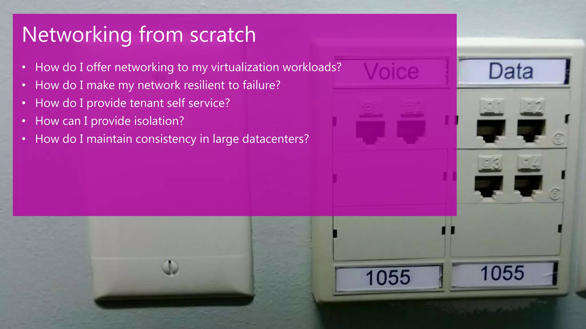
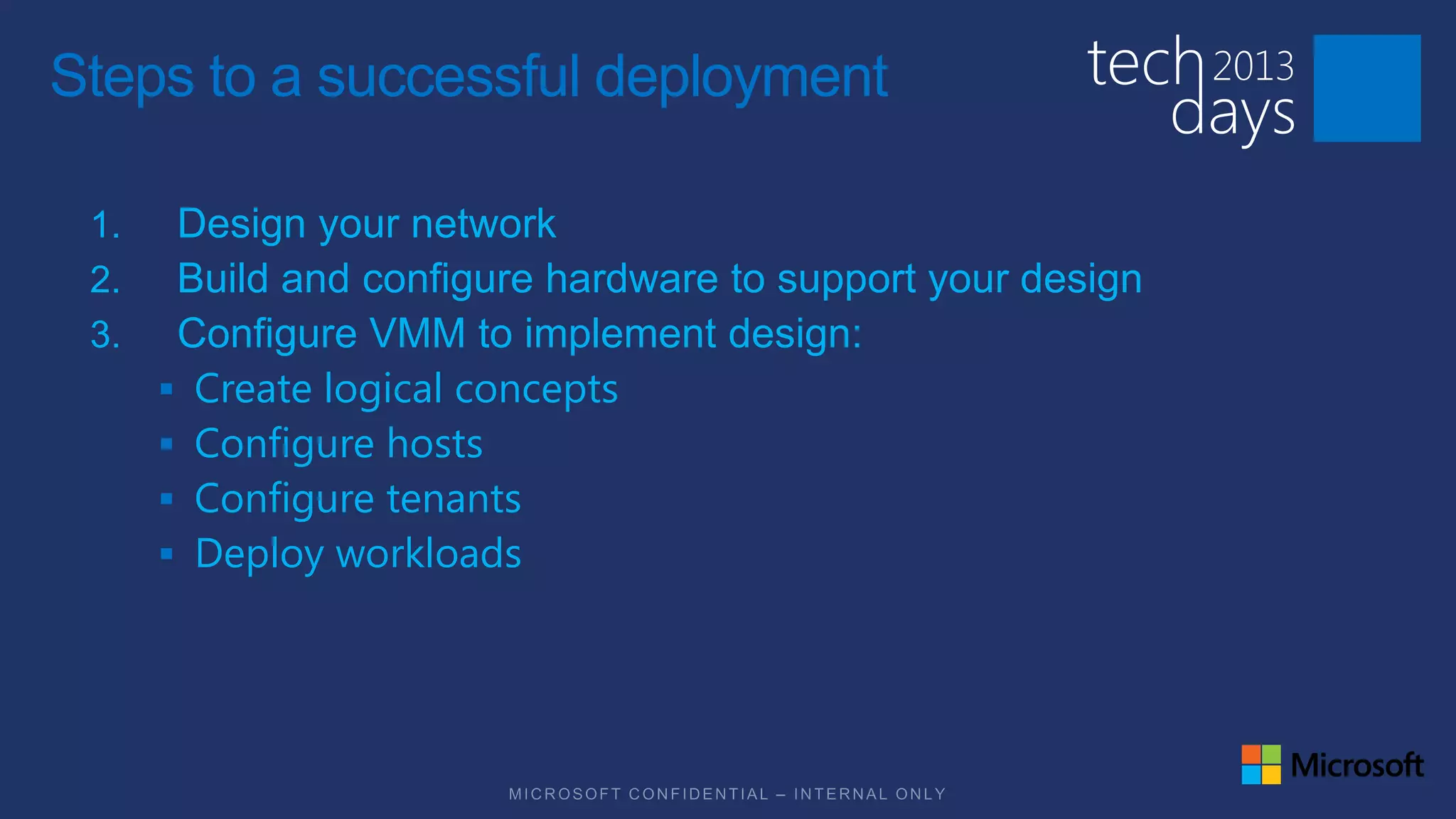

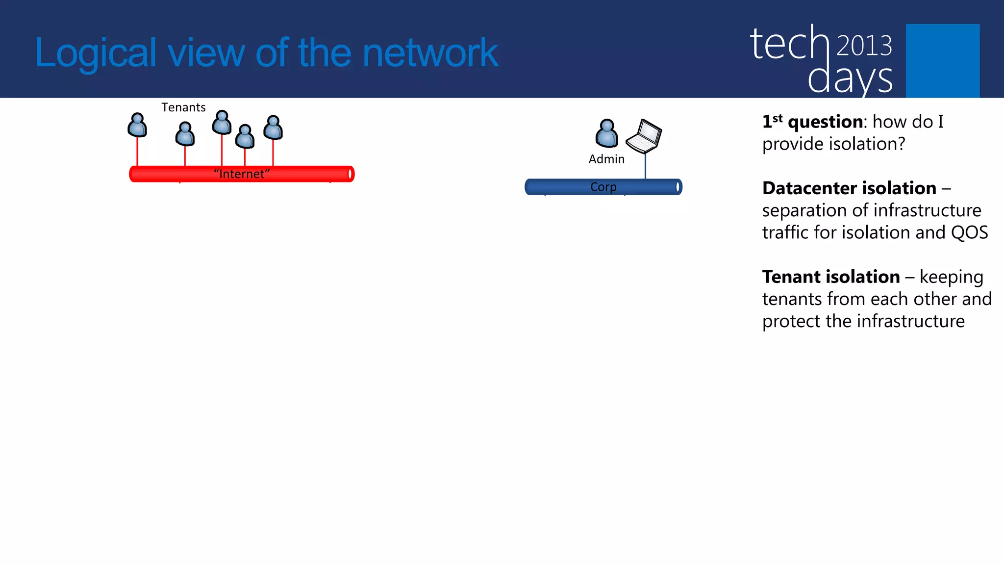
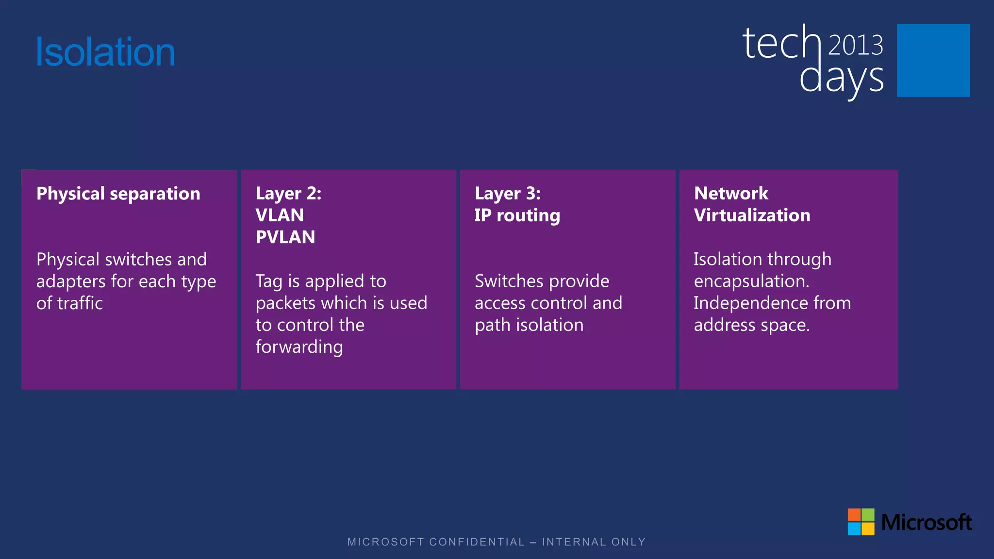
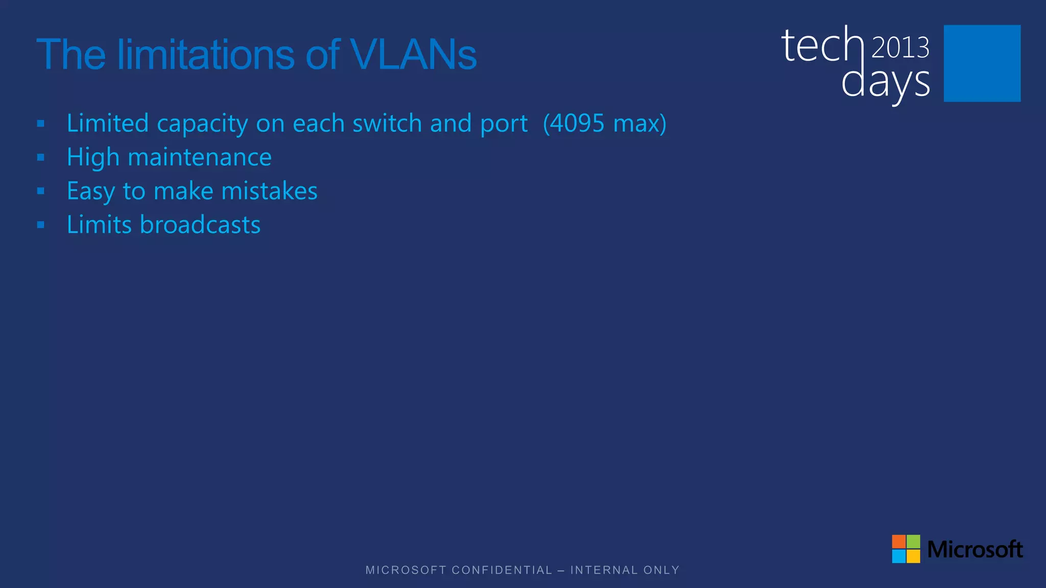
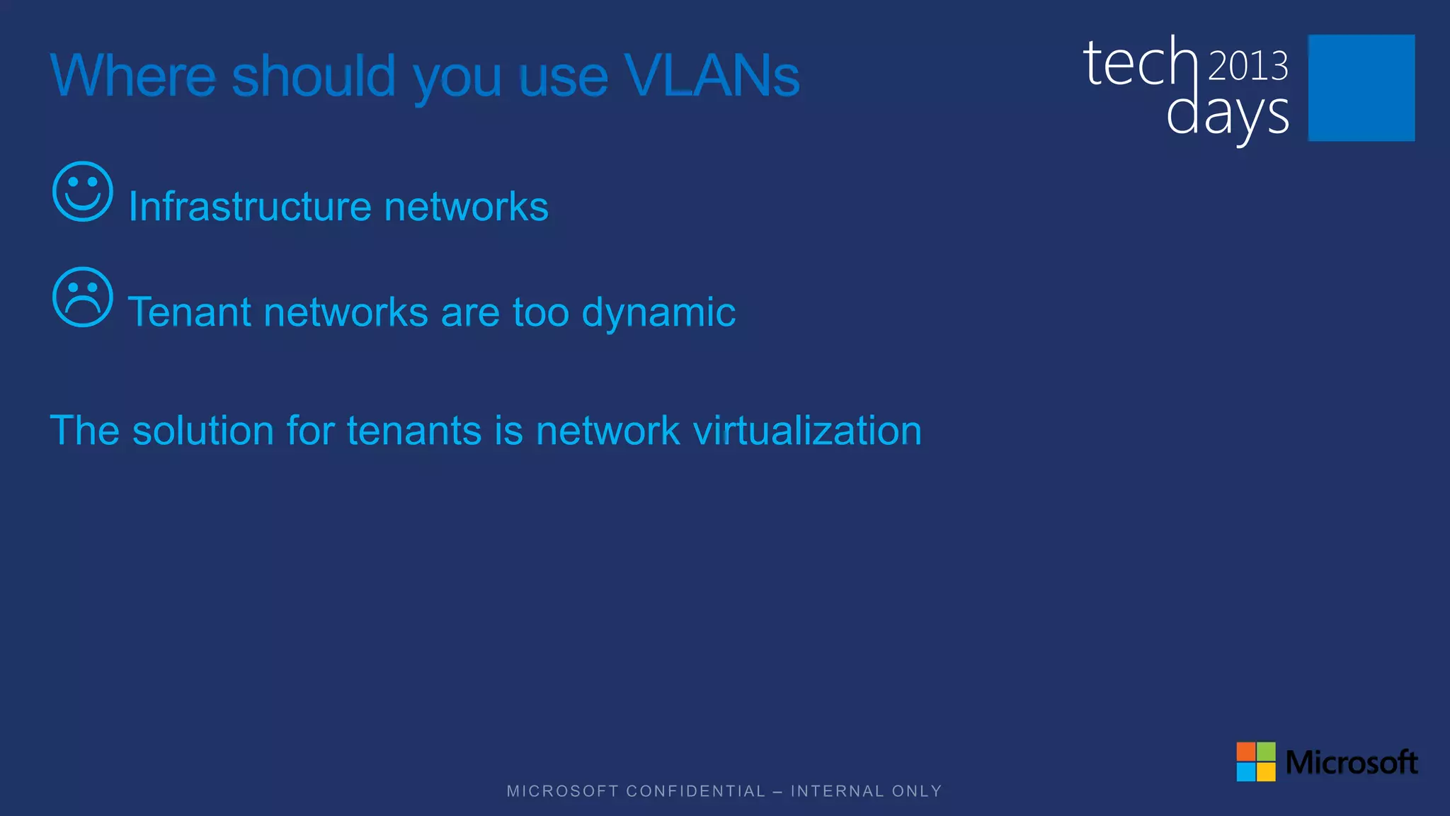
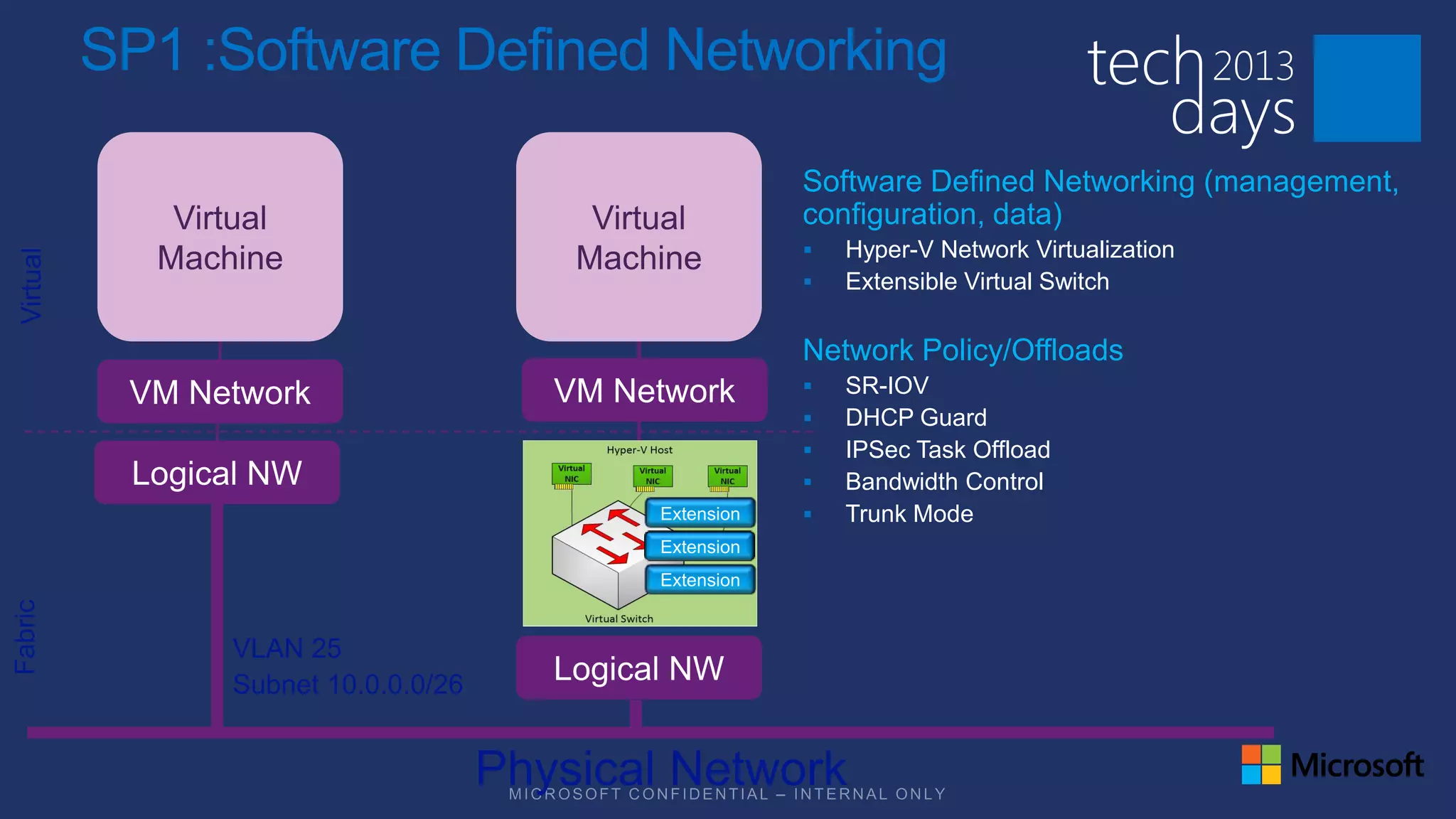
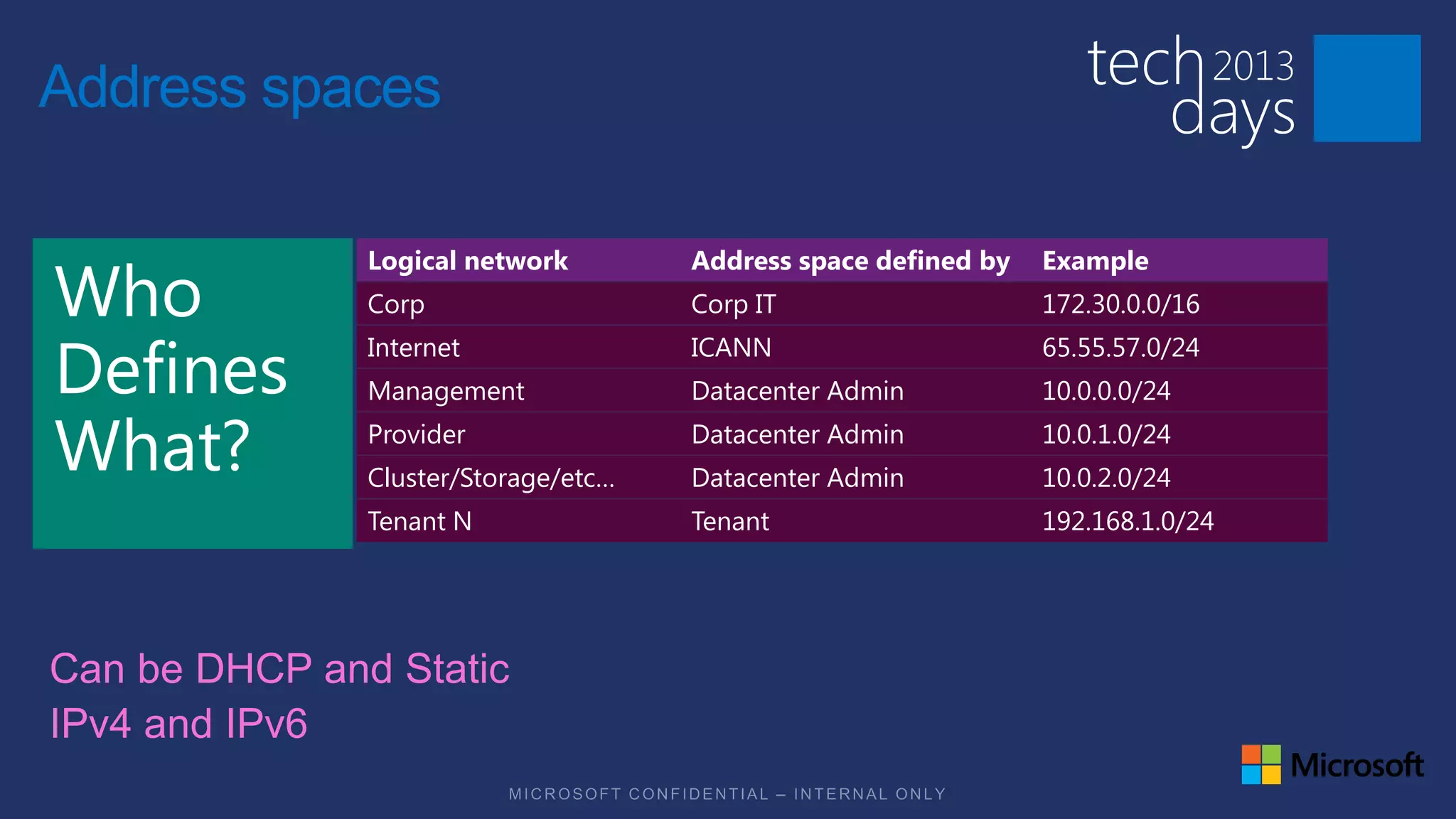
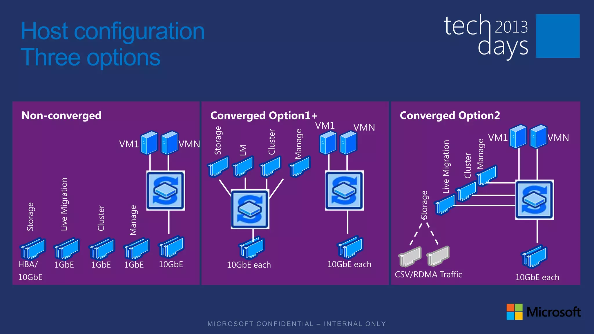
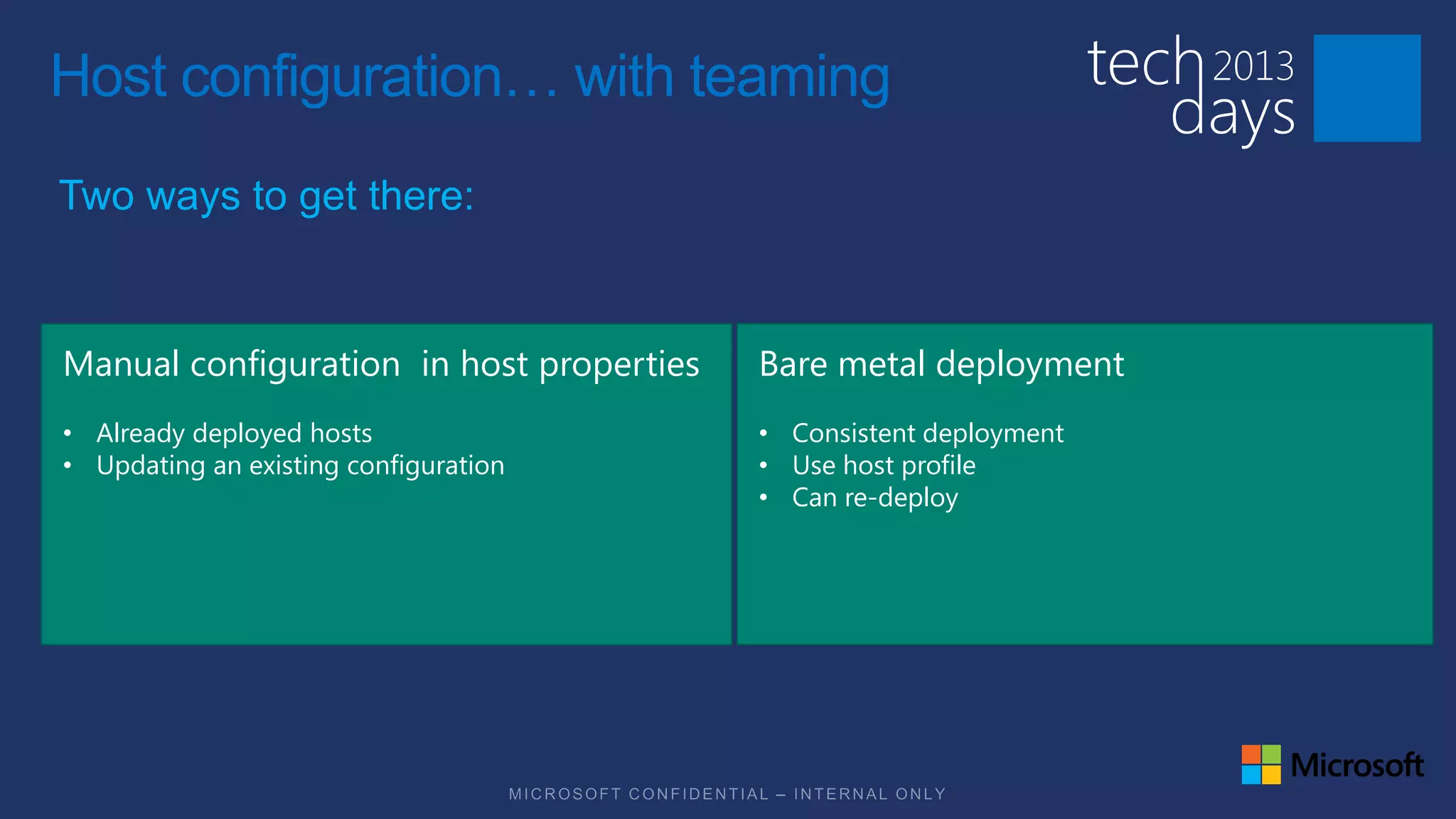
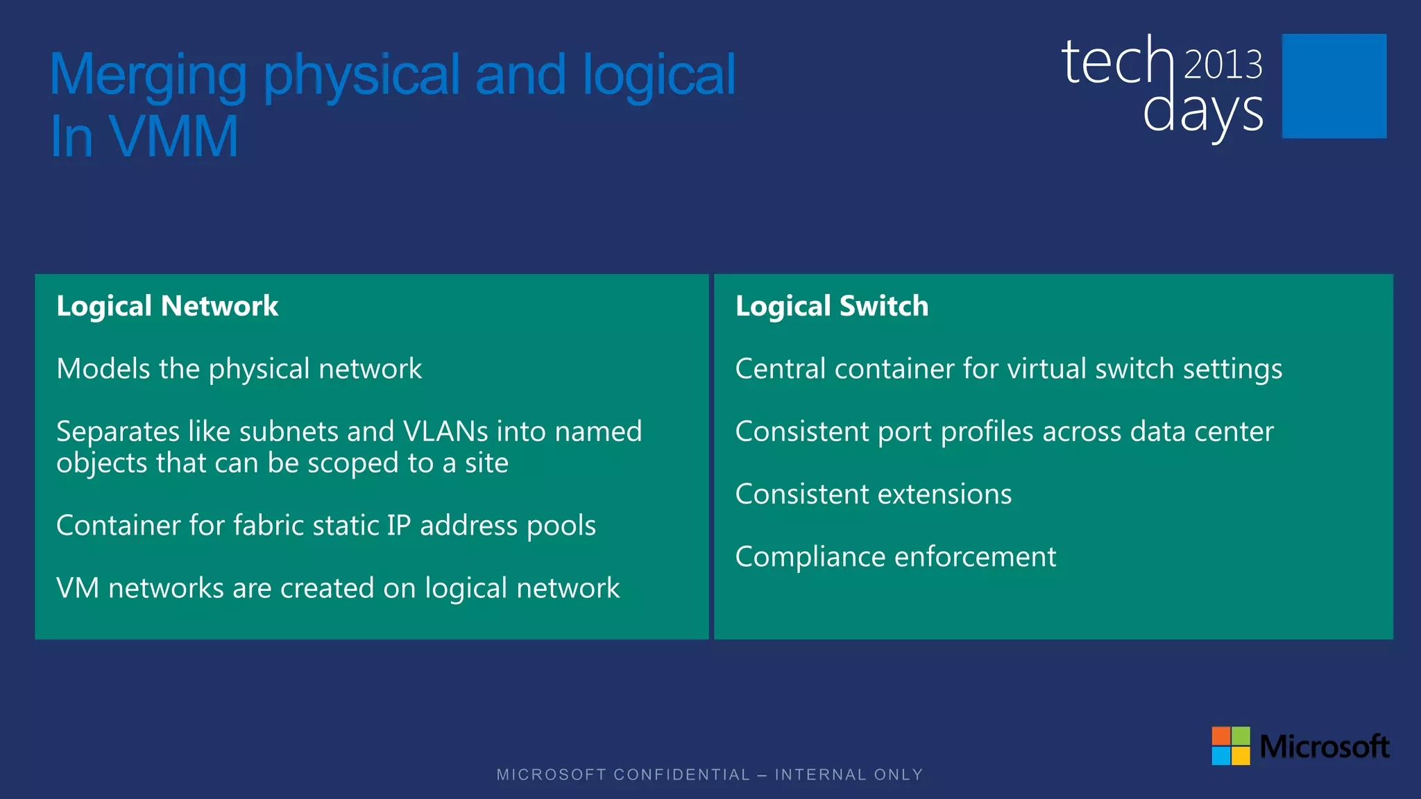
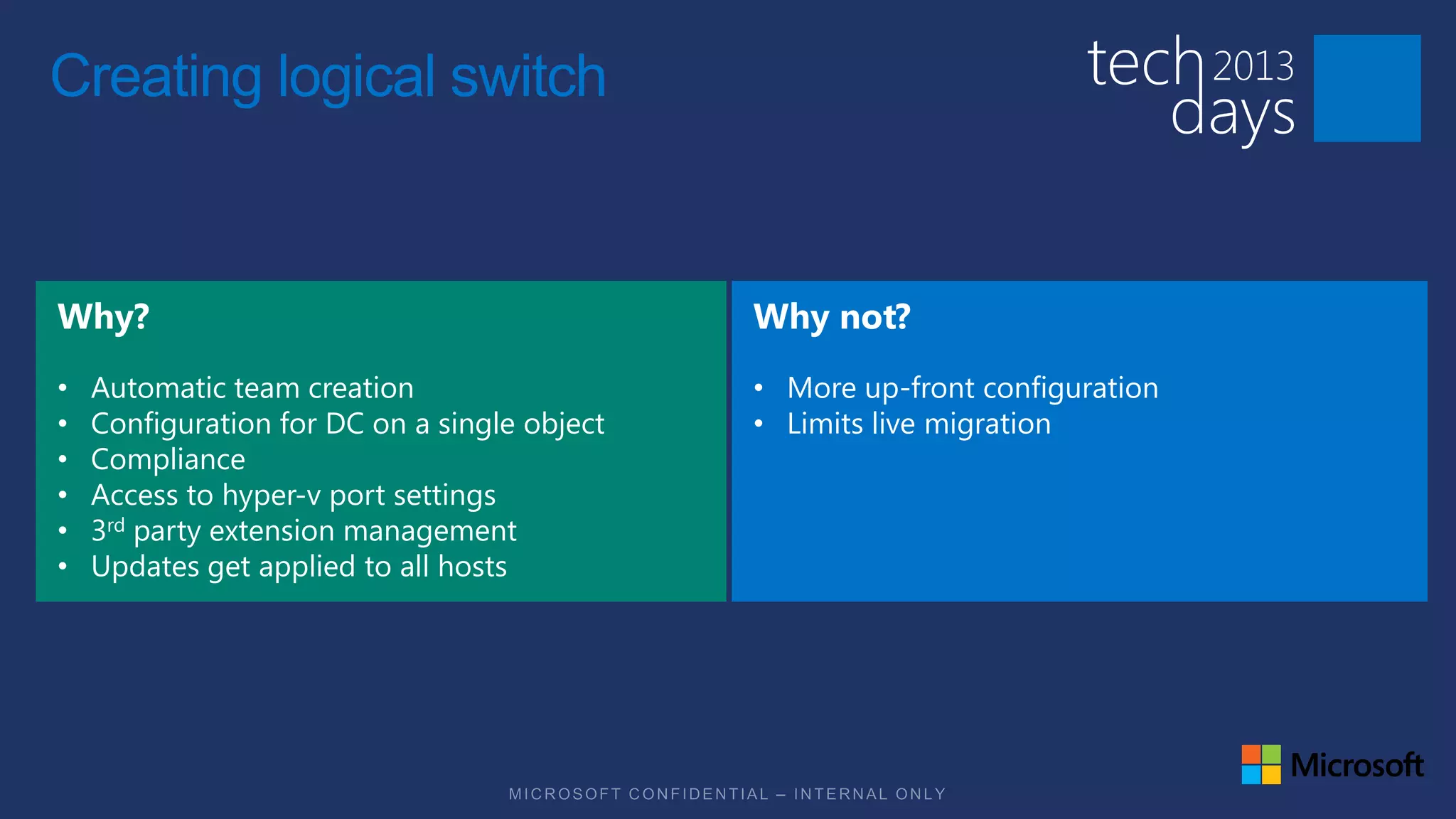
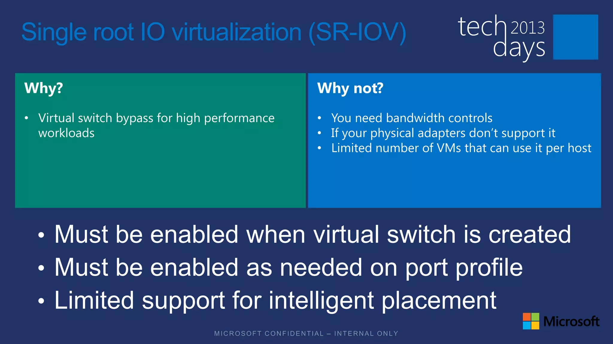

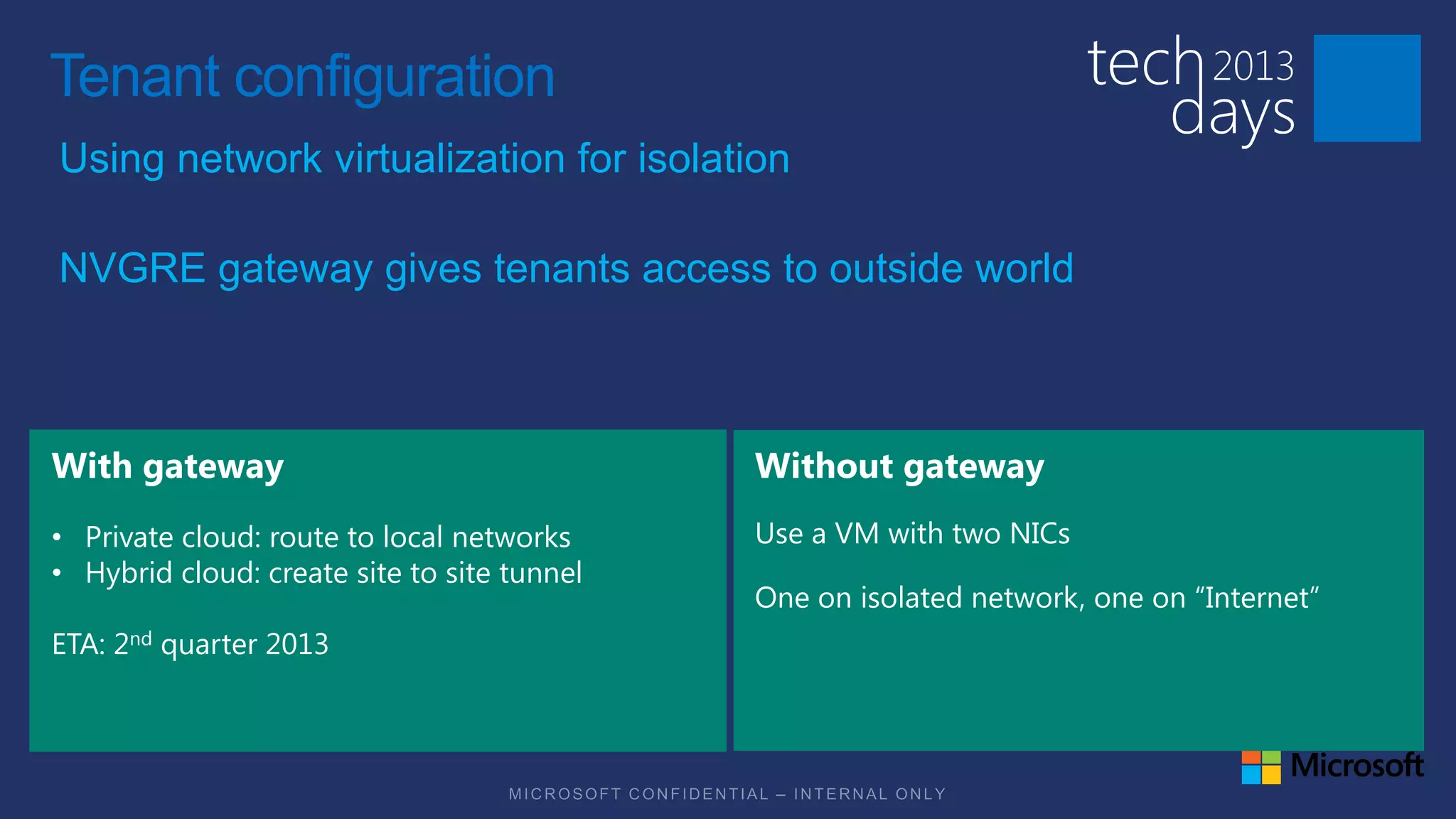
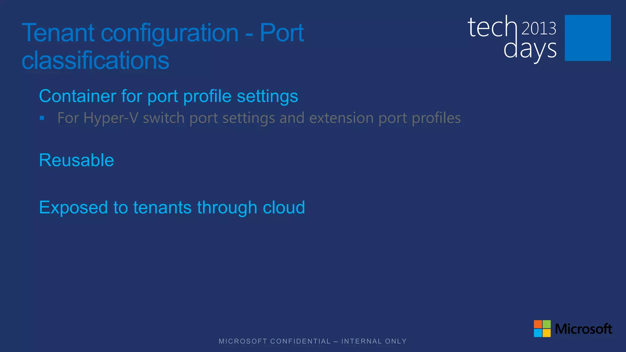
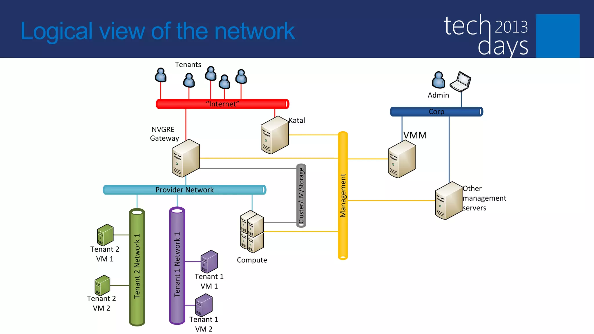
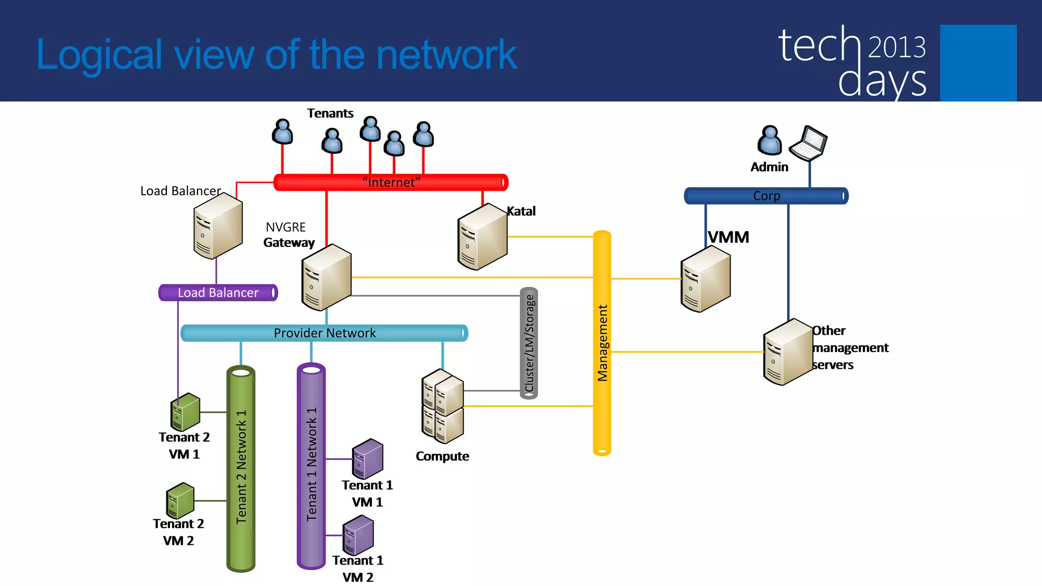
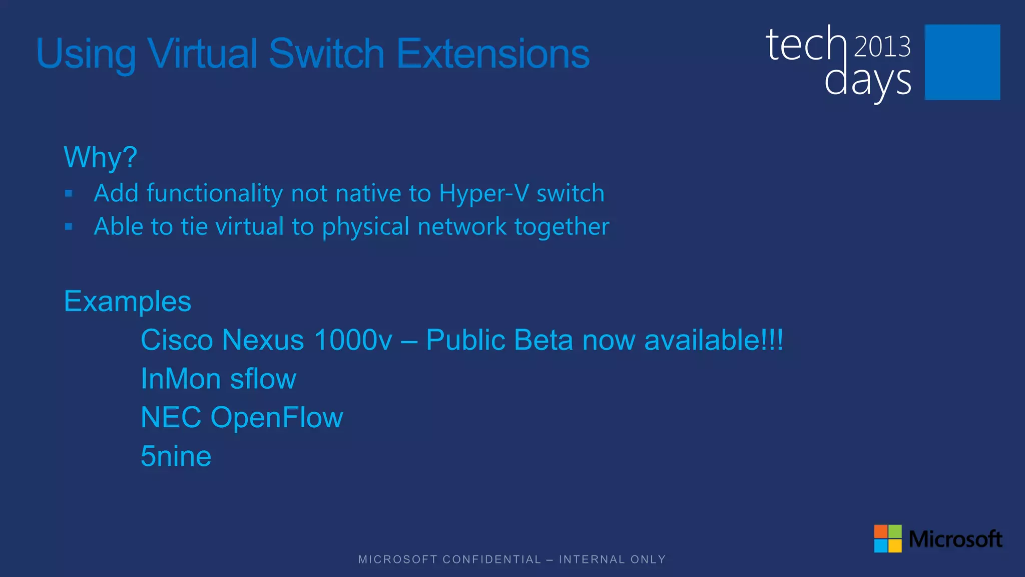


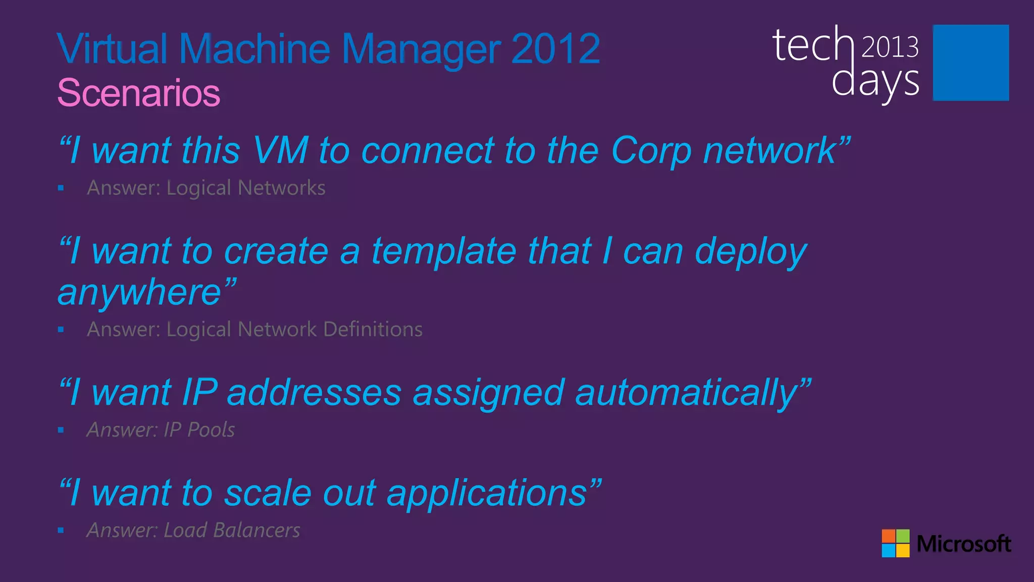
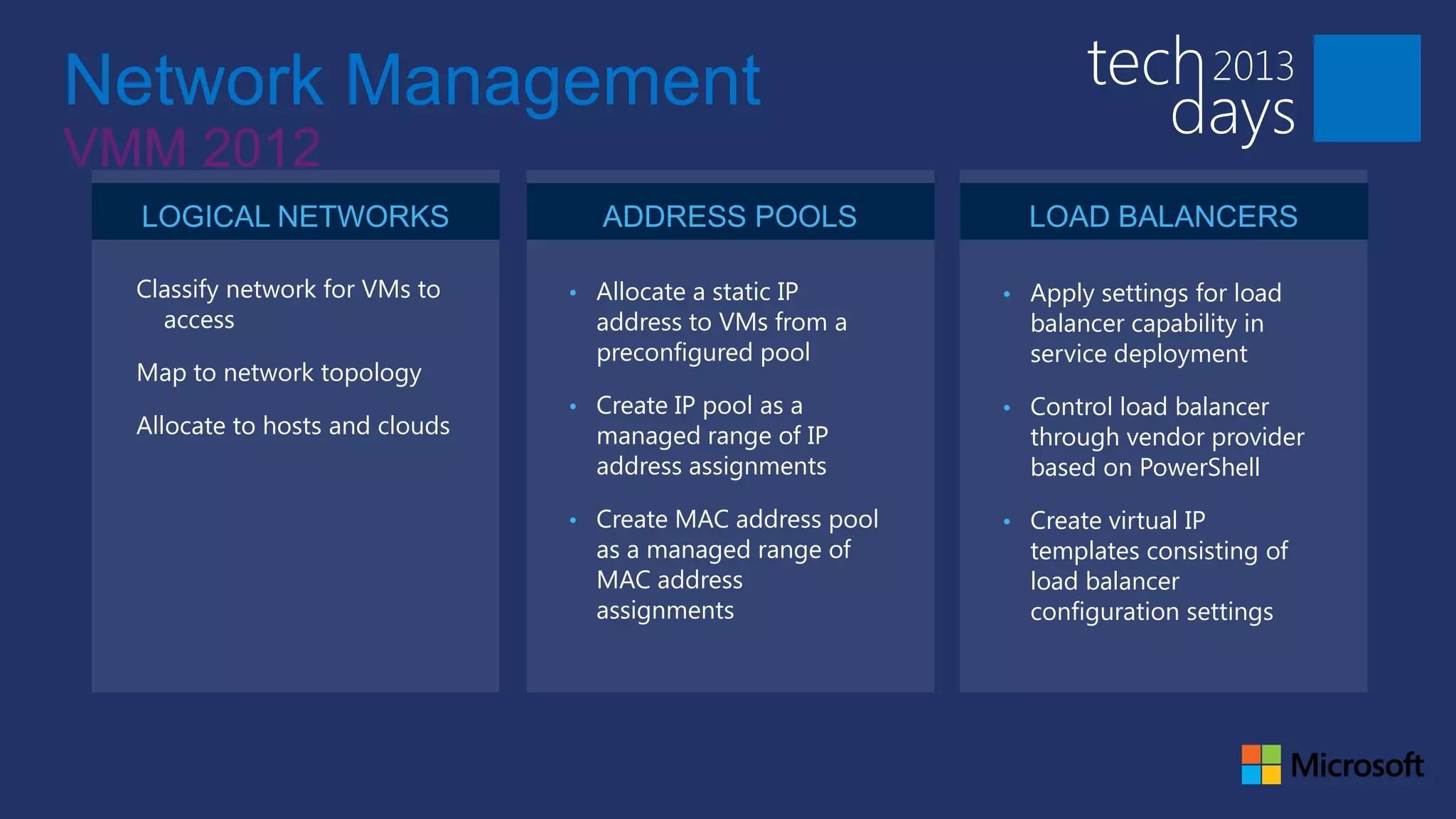
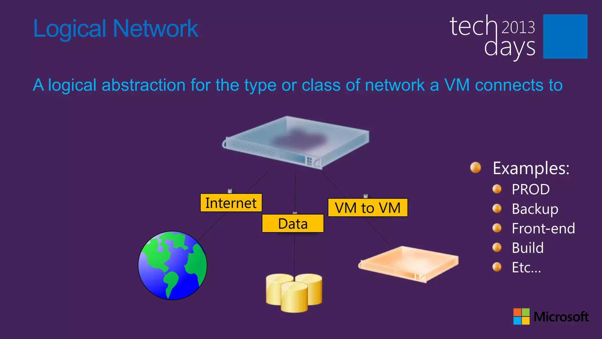
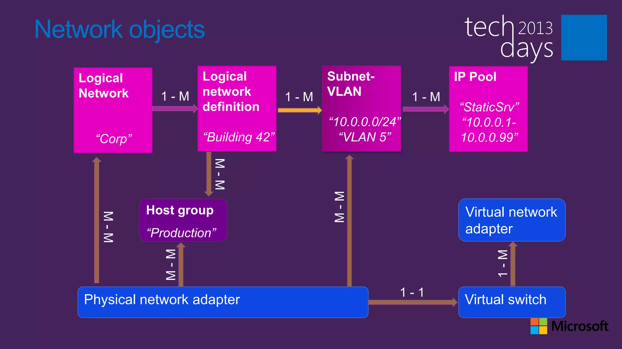
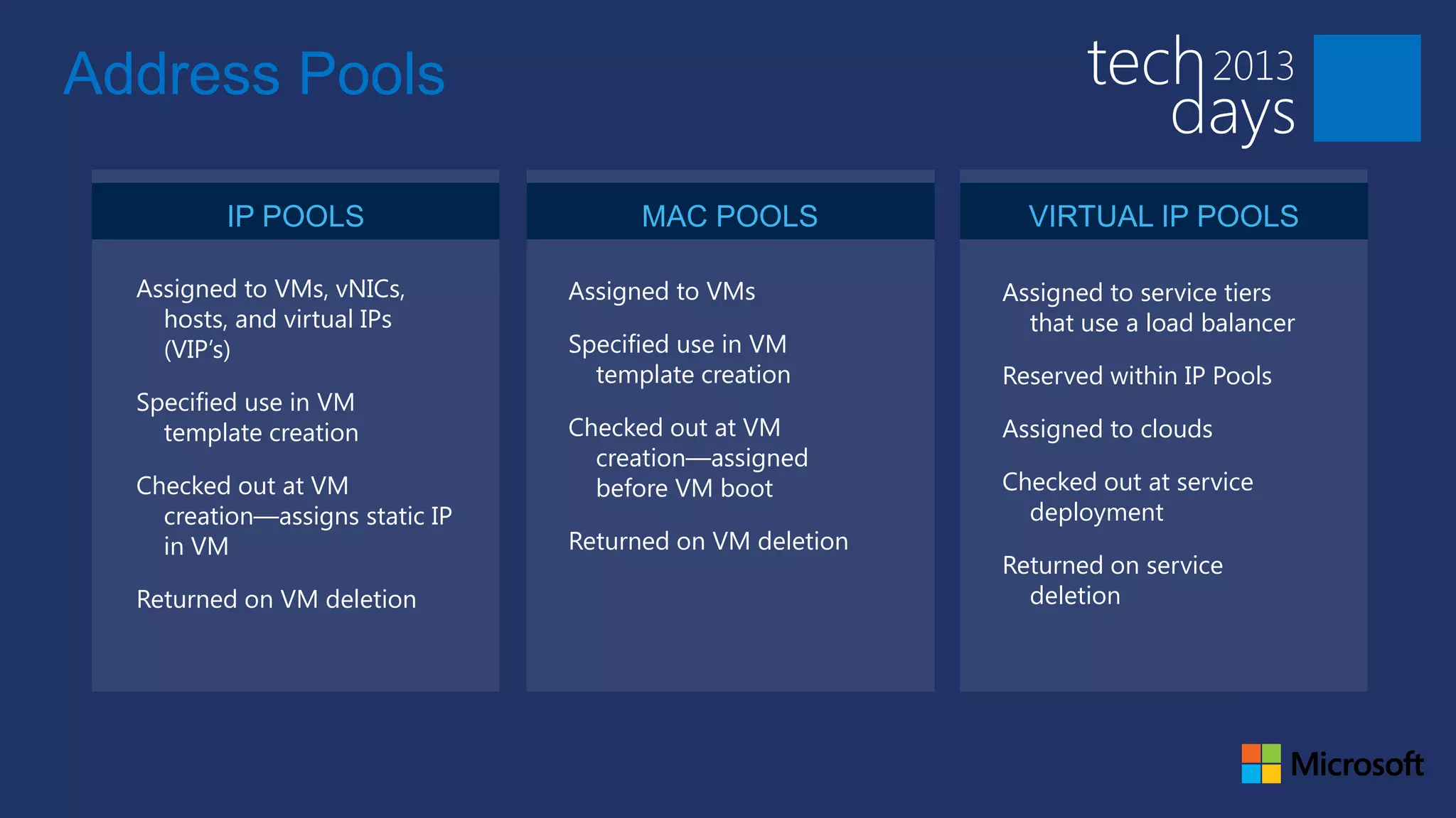
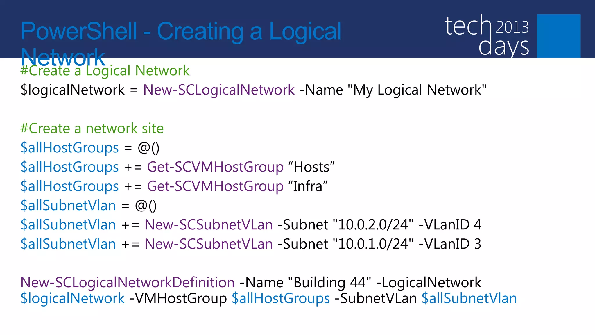
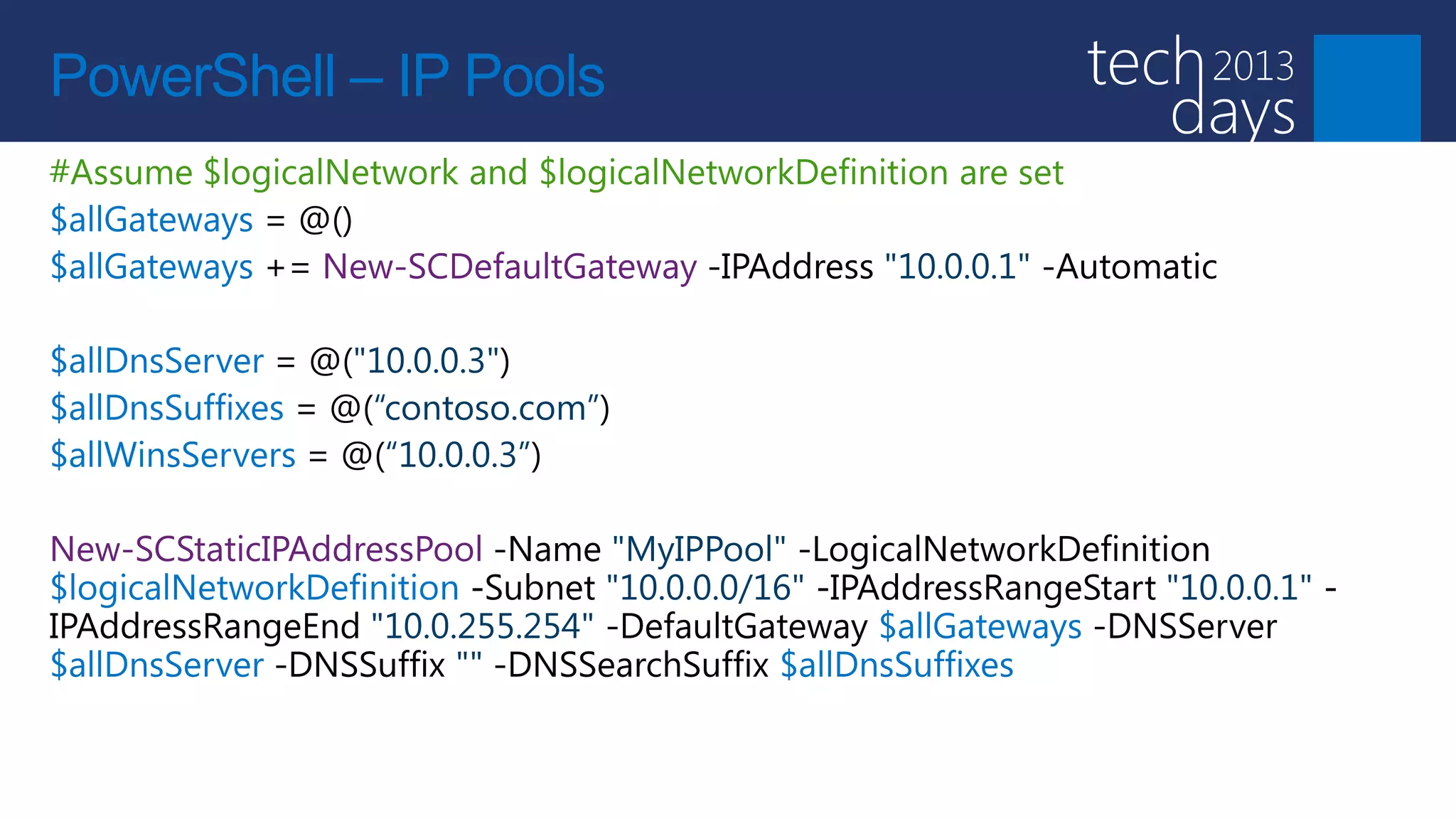
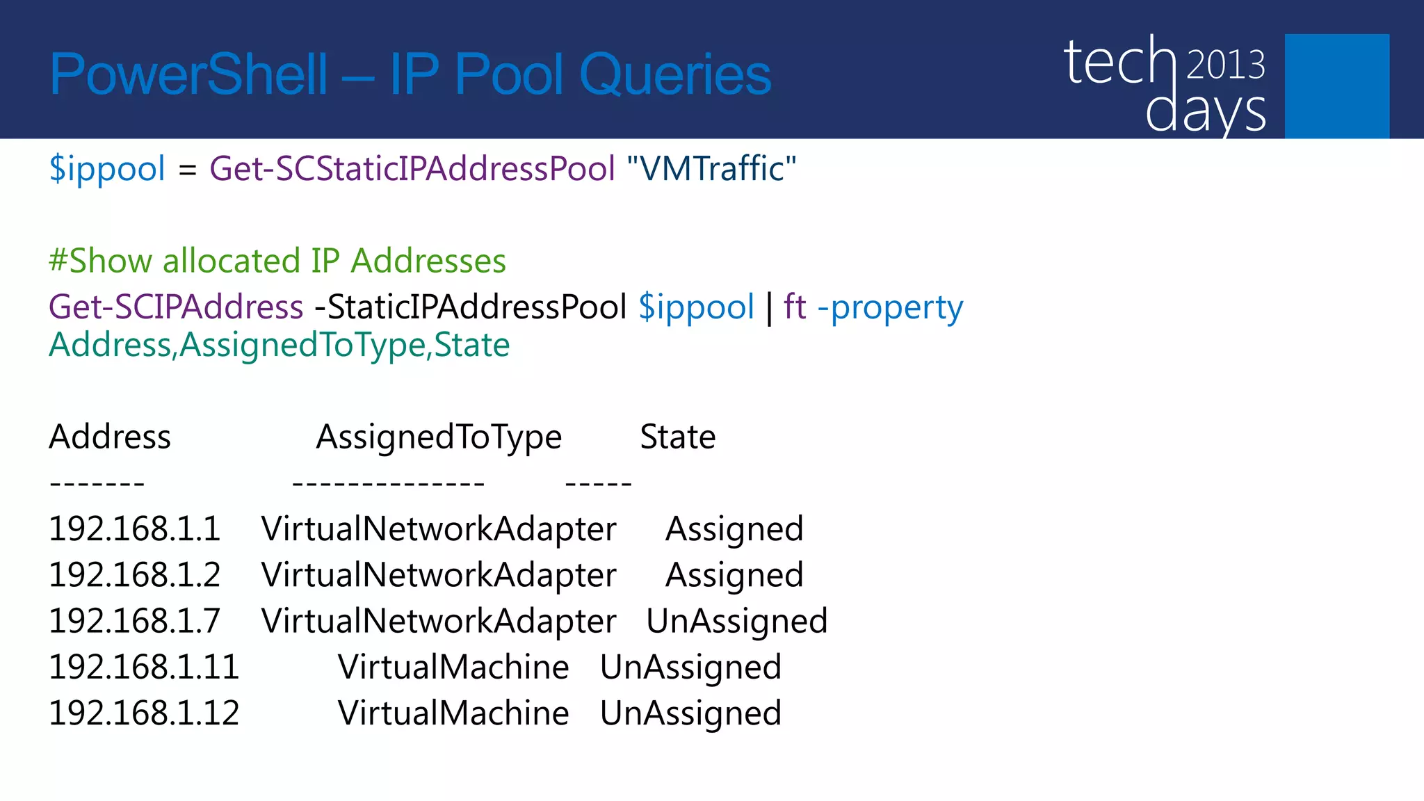
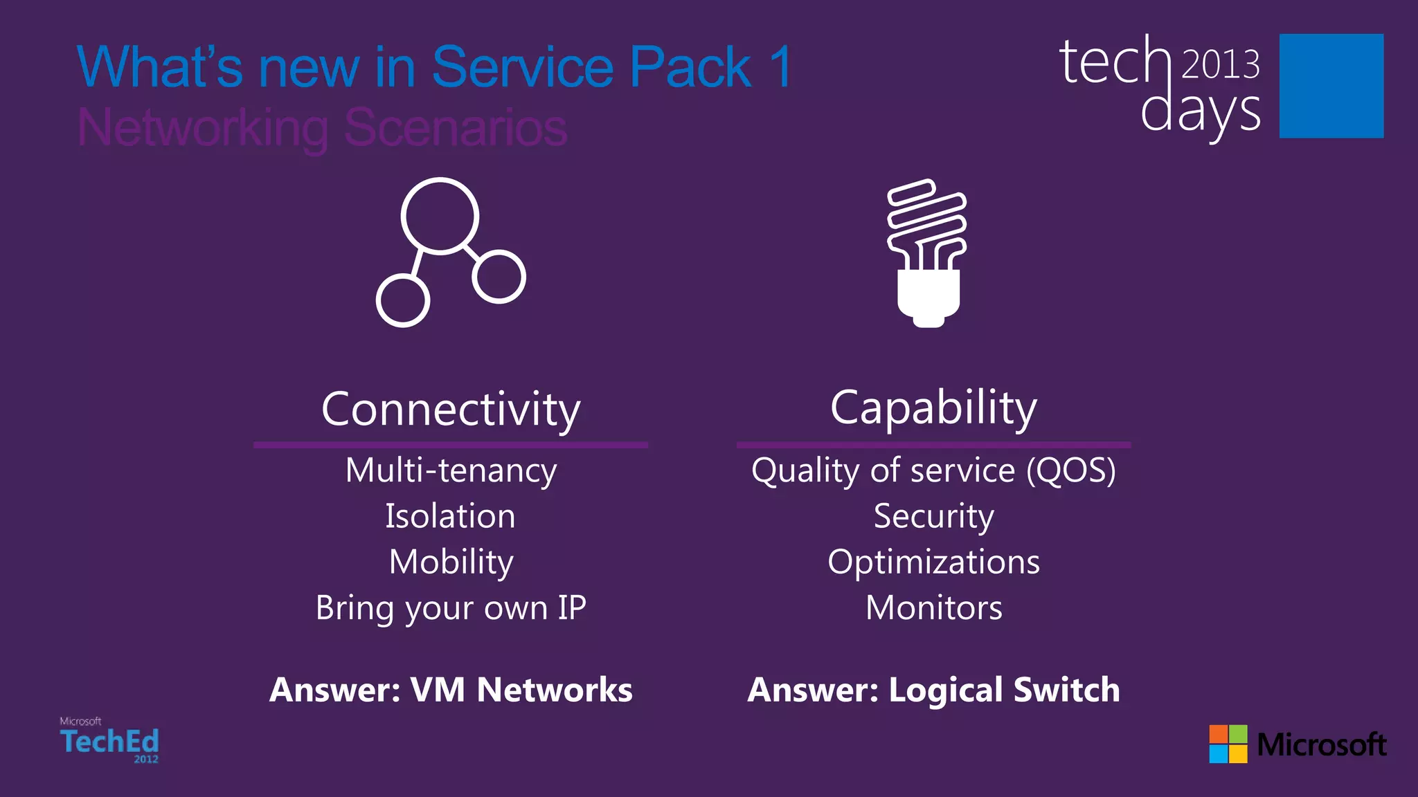
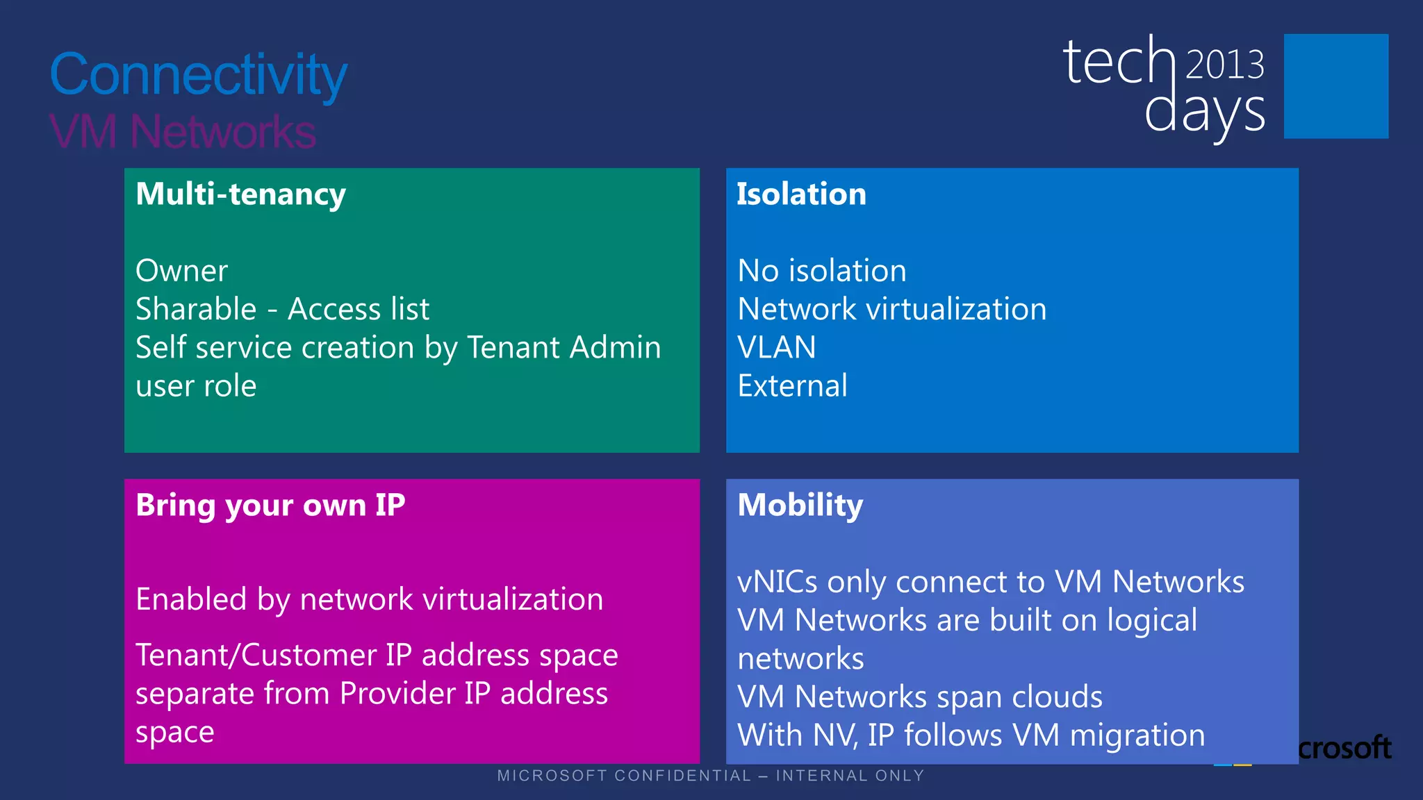
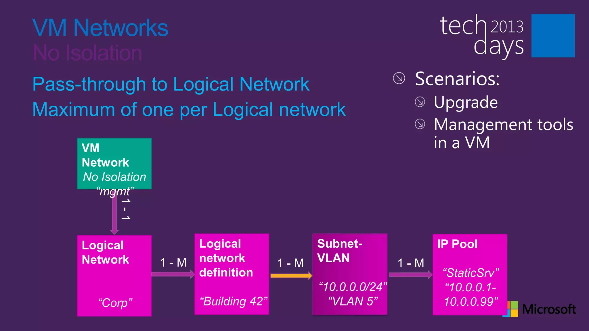
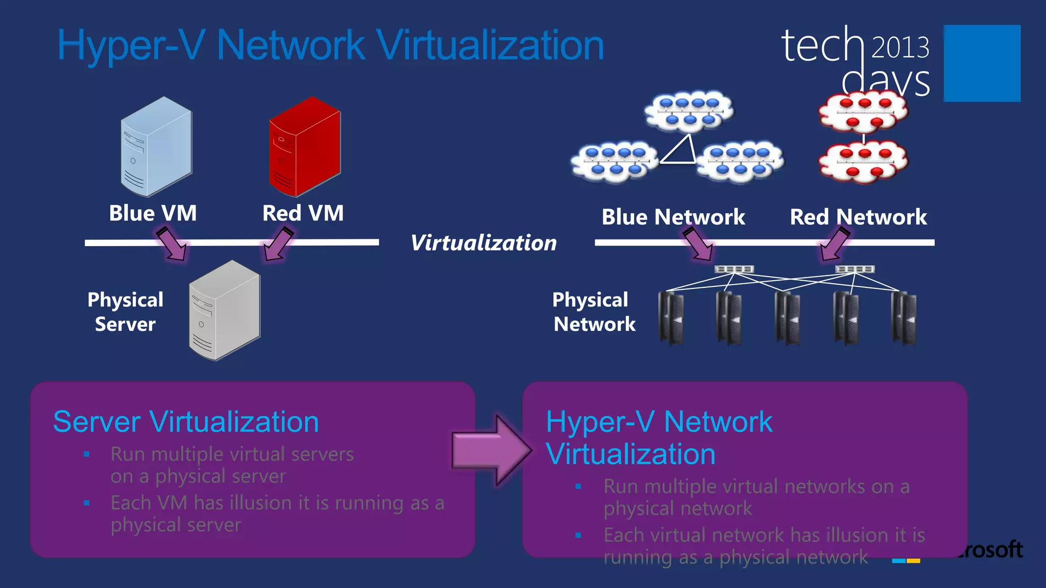
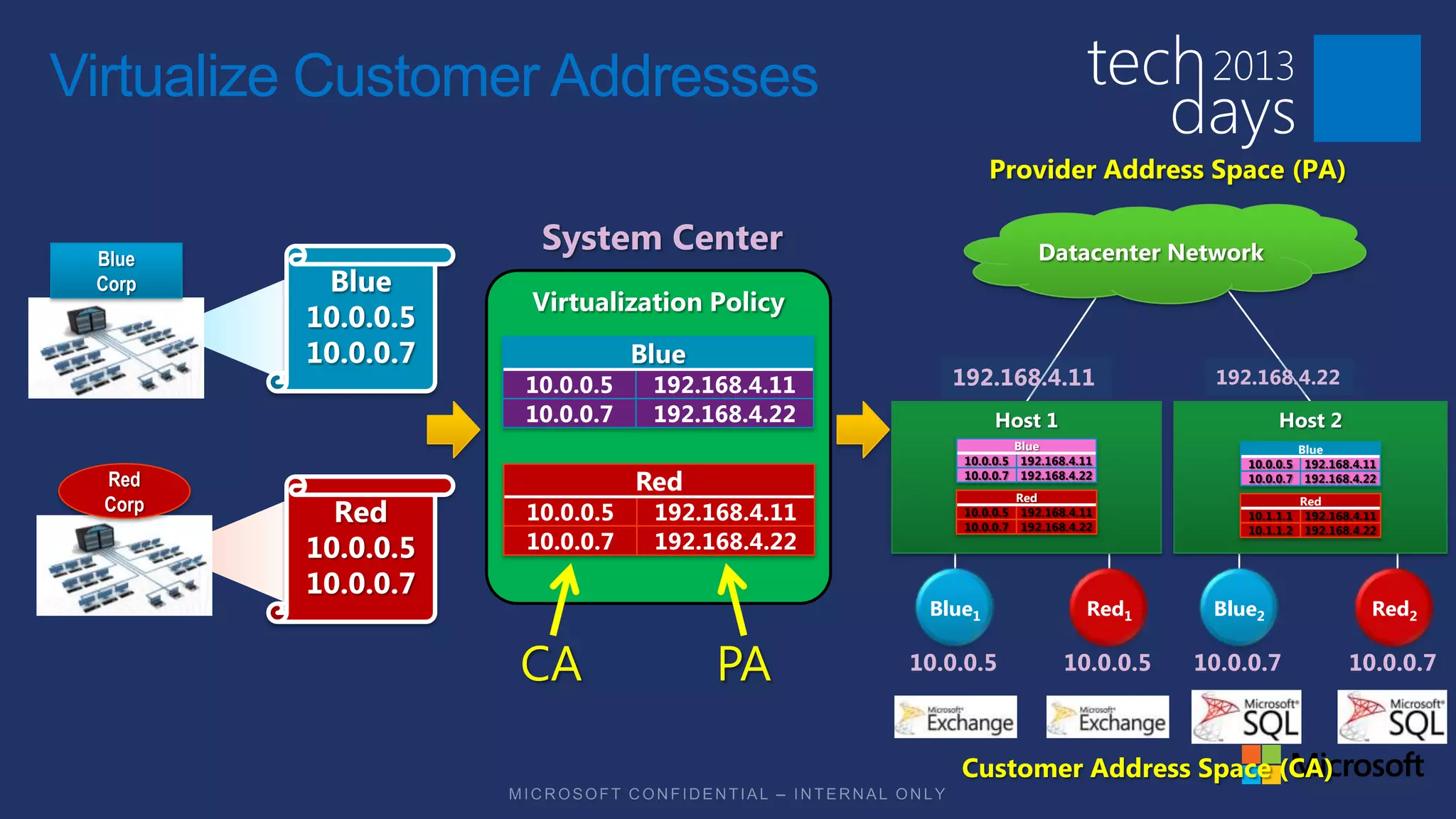
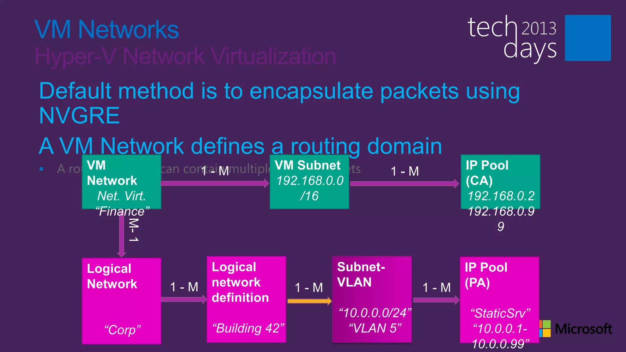
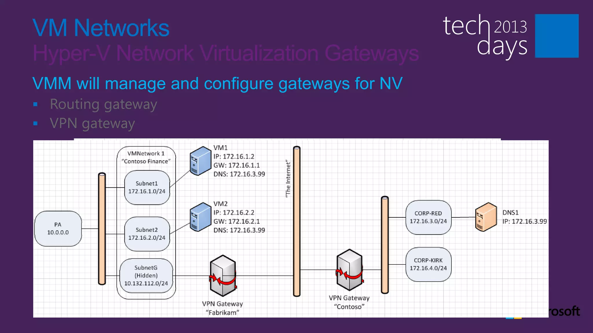
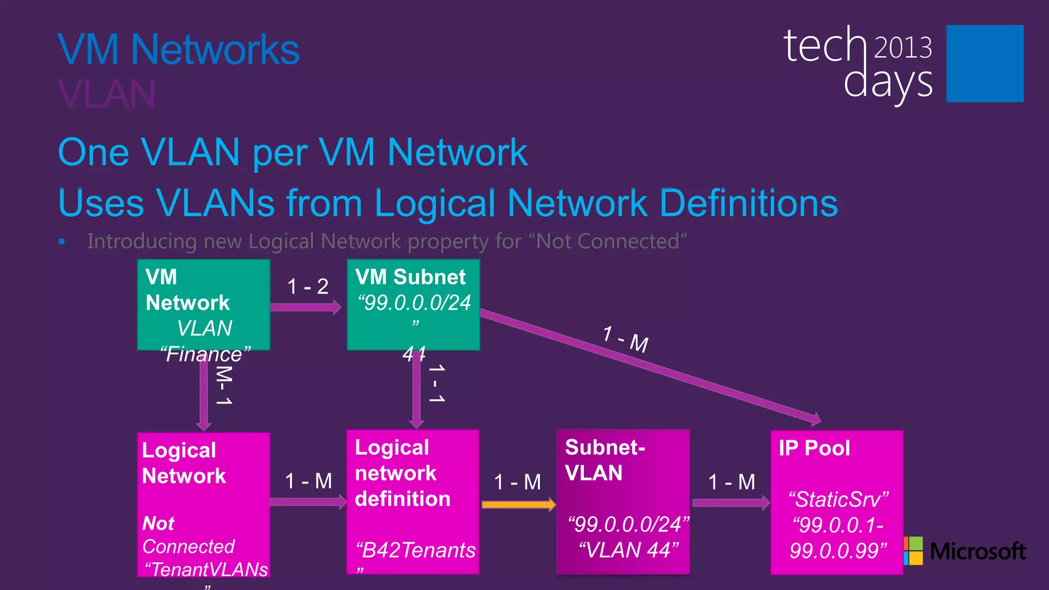
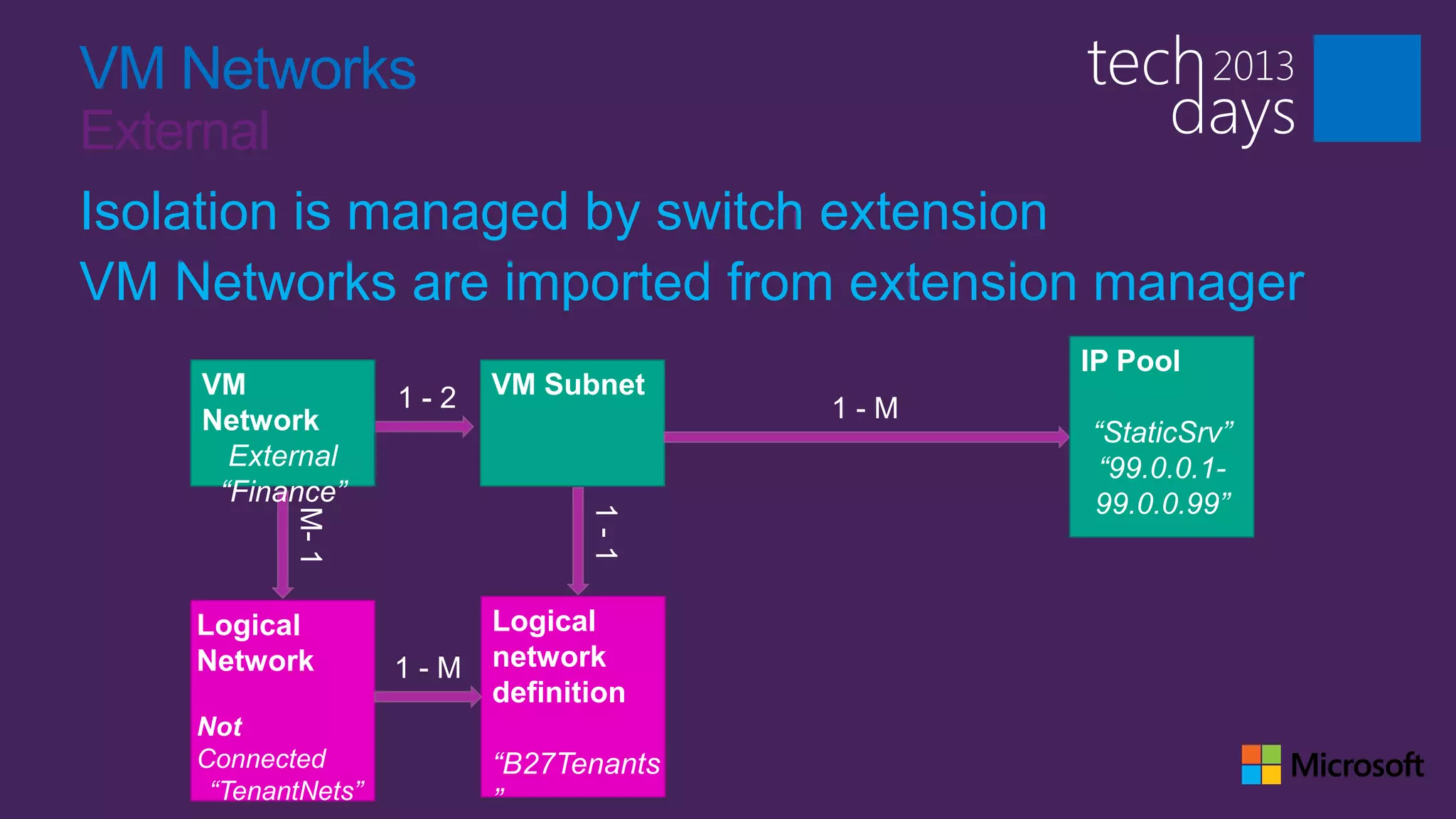
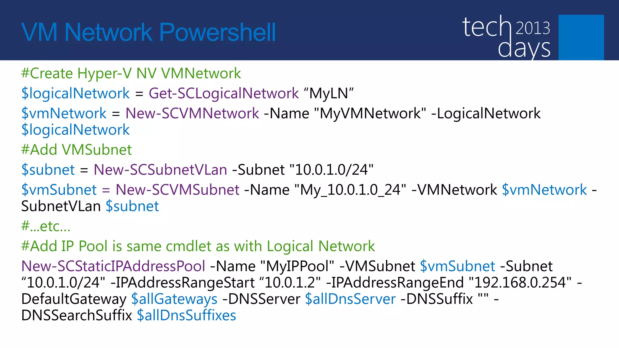

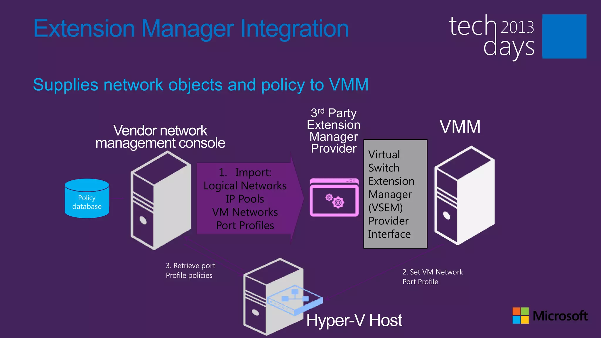
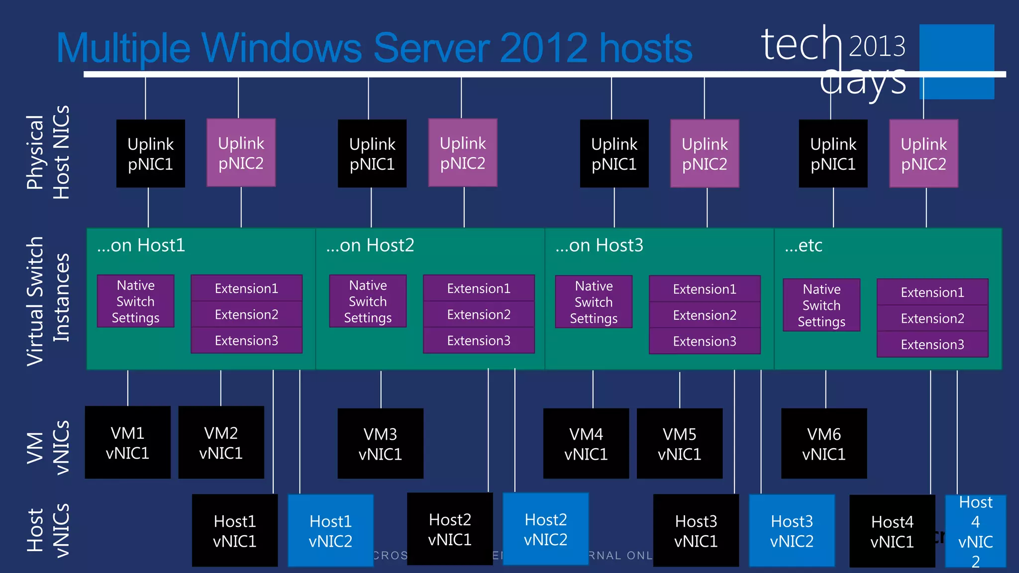
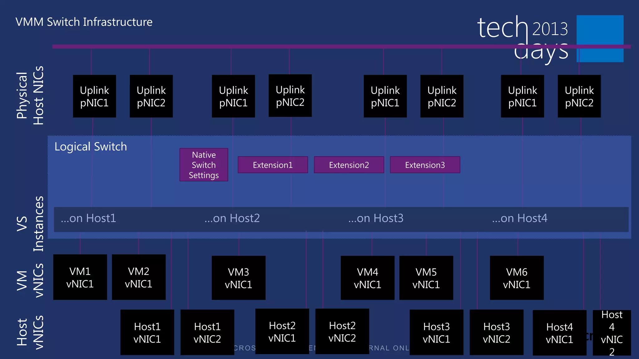
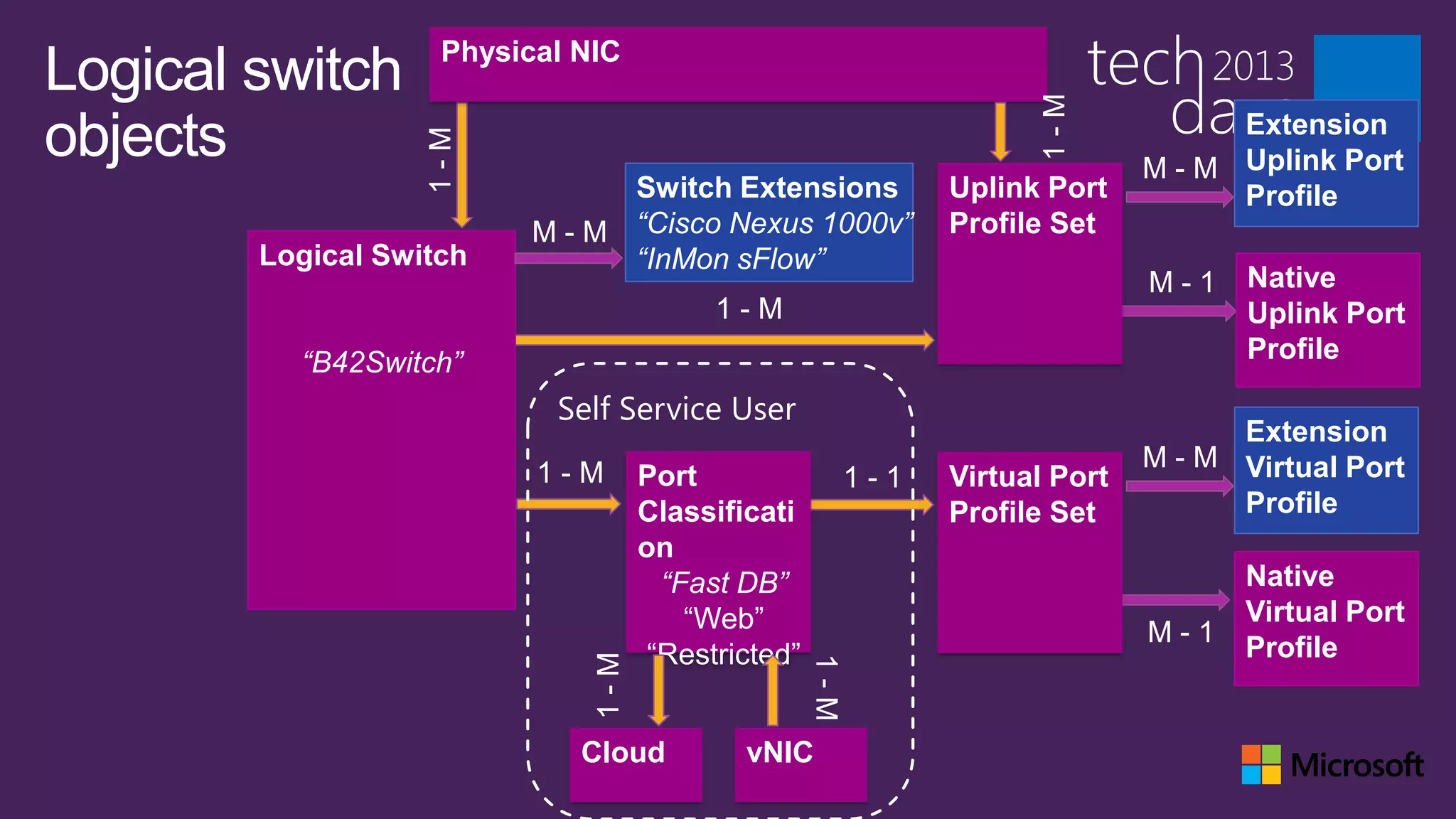


The document discusses steps for deploying a successful virtual network, including designing the network, building and configuring hardware, and configuring the virtual machine manager. It covers providing isolation through techniques like VLANs and software defined networking. Topics include logical network addressing, host configuration options, and creating logical switches. Tenant configuration using network virtualization is described for isolation.