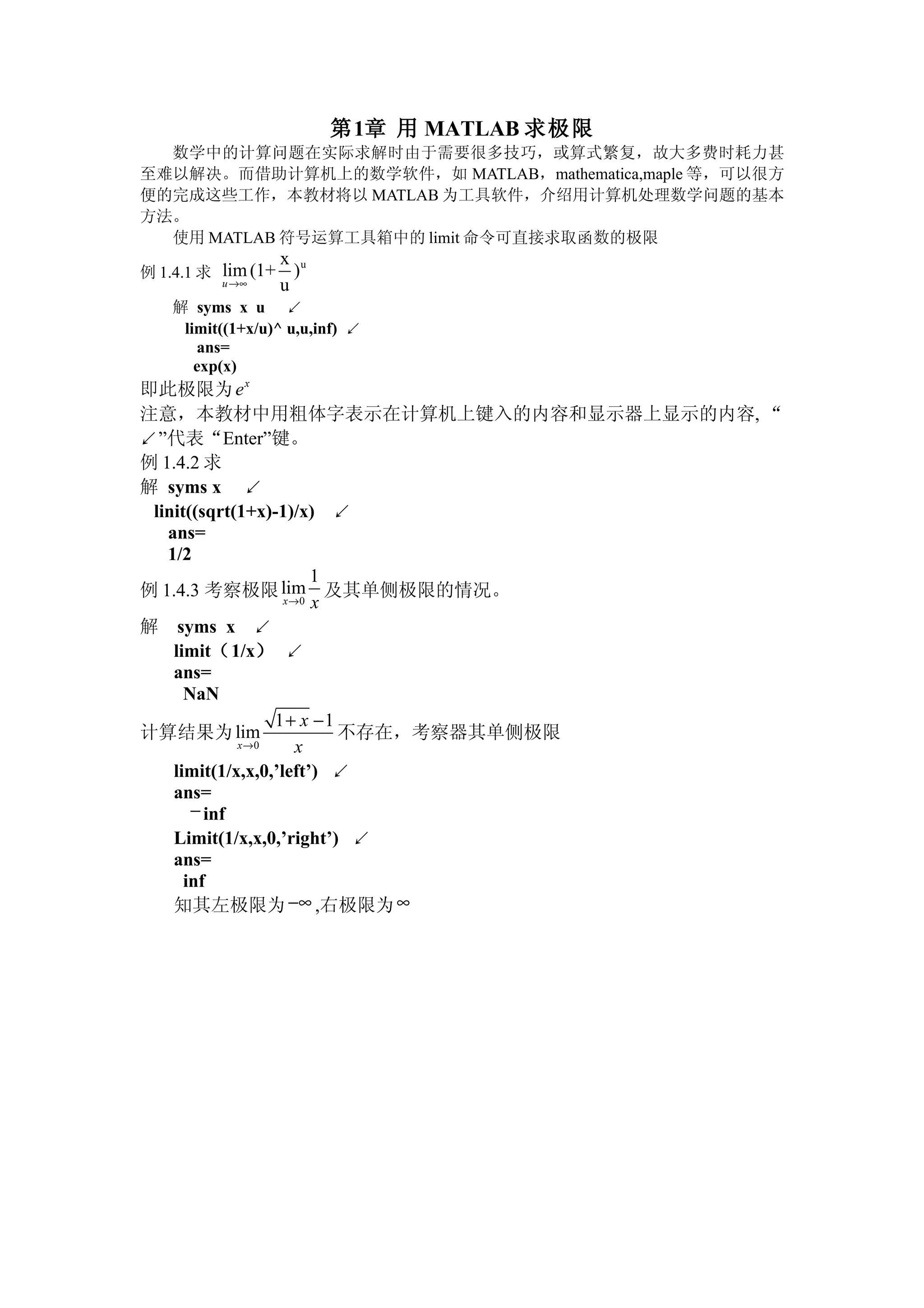
DC biasing applies fixed voltages to transistors to place them in an operating region for amplification. The operating point defines the transistor's quiescent operating conditions under DC. Stability refers to a circuit's insensitivity to parameter variations like temperature. Emitter-stabilized and voltage divider biasing improve stability over fixed biasing by incorporating an emitter or voltage divider resistor. Feedback biasing further increases stability by introducing negative feedback from collector to base.
This document provides a user manual for a CT-1016-5G 16 Bands Antenna Jammer. It lists accessories including the main unit, power adapter, car charger, and 16 omni antennas. It describes how to install and operate the device, noting the device should be kept away from electronics when powered on. Temperature operating ranges and battery recharging procedures are also outlined. Frequency bands for both European and American models are defined.
Rs flipflop or SR flipFLop
You can watch my lectures at:
Digital electronics playlist in my youtube channel:
https://www.youtube.com/channel/UC_fItK7wBO6zdWHVPIYV8dQ?view_as=subscriber
My Website : https://easyninspire.blogspot.com/
Concept of Field Effect Transistors (channel width modulation), Gate isolation types, JFET Structure and characteristics, MOSFET Structure and characteristics, depletion and enhancement type; CS, CG, CD configurations; CMOS: Basic Principles
The document describes a two port network and provides information about various parameter representations of two port networks, including:
- Z parameters define the input and transfer impedances between the two ports.
- Y parameters define the input and transfer admittances between the two ports.
- Transmission parameters (A,B,C,D) define relationships between voltages and currents at the two ports.
- Hybrid parameters also define relationships between voltages and currents at the two ports.
Examples are provided to demonstrate calculating the parameter representations for given two port networks. Additionally, the document discusses how modifying a two port network impacts its parameter representations.
1. The document derives the electromagnetic wave equation from Maxwell's equations for propagation through a homogeneous, isotropic dielectric medium where conductivity is zero and there is no charge density.
2. The wave equations for the magnetic and electric fields are obtained and shown to have the form of the general wave equation.
3. Hertz's experiment confirmed Maxwell's prediction of electromagnetic waves by generating and detecting them in 1887 using an oscillator consisting of two charged spheres separated by a spark gap.
Modern digital and analog communication syatems by b.p lathi solution mannual...Naqash Rasheed
The document discusses the benefits of exercise for both physical and mental health. It notes that regular exercise can reduce the risk of diseases like heart disease and diabetes, improve mood, and reduce feelings of stress and anxiety. The document recommends that adults get at least 150 minutes of moderate exercise per week or 75 minutes of vigorous exercise per week to experience these benefits.
Here are the key steps to analyze the emitter-stabilized bias circuit:
1. Analyze the base-emitter loop using KVL:
VCC - IBRE - VBE - IERE = 0
2. Solve for IB and substitute into IE = βIB
3. Analyze the collector-emitter loop using KVL:
VCC - IC(RC + RE) - VCE = 0
4. Solve simultaneously with the base-emitter loop equation to find Q-point values of IB, IC, VBE, VCE.
The addition of the emitter resistor RE provides negative feedback which helps stabilize the operating point against variations in β and temperature. This makes the
This document discusses transistors and thermal runaway. It begins by providing the author's name and ID number. It then discusses the common emitter configuration of transistors and provides an equation. It explains various terms in the equation such as collector current, base current, reverse saturation current, minority charge carriers, and temperature. It notes that increasing temperature and minority charge carriers can increase the reverse saturation current. It discusses that collector current produces heat and that thermal runaway is the self destruction of an unstabilized transistor due to heat. It states that a heat sink can be used to avoid thermal runaway in transistors.
Okay, here are the steps to find the velocity of the rocket at t = 10s:
1) Take the derivative of the position function x(t) to get the velocity function v(t):
v(t) = 4 + 14t + 15t^2 - 1.4t^3
2) Plug t = 10s into the velocity function:
v(10) = 4 + 140 + 1500 - 140 = 1404 m/s
So the velocity of the rocket at t = 10s is 1404 m/s.
IC Design of Power Management Circuits (II)Claudia Sin
The document discusses various aspects of integrated circuit design for power management circuits. It covers control loop design including biasing circuits, oscillators, comparators and operational amplifiers. It also discusses power stage design such as power transistors, synchronous rectification and active diodes. Finally it discusses peripheral circuits including undervoltage lockout, overcurrent protection and soft start circuits. The document provides guidelines and examples for analog integrated circuit design of switching converters and related circuits.
This document provides an index and summaries of 100 transistor circuit designs. It begins with introductions on how transistors work and suggestions for building circuits using common components. The index lists various circuit categories and specific projects, many of which can be built with minimal components. The goal is to get readers experimenting with transistors through practical examples.
A successive approximation analog-to-digital converter (SAR ADC) operates by using a binary search process to convert an analog input voltage into a digital code. It consists of a sample and hold circuit, analog comparator, successive approximation register, and internal reference digital-to-analog converter. The SAR ADC uses a charge redistribution architecture with capacitors of weighted values, and performs conversion in three steps: sample mode, hold mode, and redistribution mode, where the actual conversion occurs by successively connecting capacitor plates to a reference voltage.
At low frequencies, we analyze transistor
using h-parameter. But for high frequency analysis the
h-parameter model is not suitable, because :-
(1) The value of h-parameters are not constant at high frequencies.
(2)At high frequency h-parameters becomes very complex
in nature
The cascode is a two-stage amplifier that consists of a common-emitter stage feeding into a common-base stage.
This a brief description of how cascode amplifiers function what are the factors that determine the bandwidth of the circuit.
The document discusses the analog to digital conversion process. It explains that sounds are analog waves but computers are digital so an conversion is needed. The sound card contains an analog-to-digital converter (ADC) that samples sounds and converts them to binary digits and a digital-to-analog converter (DAC) that converts the digital signals back to analog waves for playback. The key parameters for conversion are the sampling rate, which must be over twice the highest frequency to avoid quality issues, and the bit depth, which determines the number of possible values and thus the resolution/quality. Higher rates and depths allow for better quality recordings.
The document provides installation and wiring instructions for TECNOLOGIC K series controllers. It specifies that the controller is intended for indoor use and should be mounted in an easily accessible location with minimal vibrations that avoids corrosive gases, water or condensation. Wiring guidelines are provided for different input and output types, including thermocouples, RTDs, voltage/current signals, and relays. Configuration and programming procedures are outlined.
Clippers and clampers are diode-based circuits used to modify signal waveforms. Clippers eliminate portions of an input signal to "clip" the waveform, and are used to remove noise or create new waveforms. They come in series and parallel types. Series clippers place the diode in series with the load, and clip voltages that don't forward bias the diode. Parallel clippers take the output across the diode, producing the voltage when it is not conducting. Clampers "clamp" a signal to a different DC level using a capacitor, diode, and resistor. The capacitor stores a reference voltage to set the output level when the diode is non-conducting.
This document discusses different biasing techniques for MOSFETs, including biasing with a feedback resistor and voltage divider bias. It provides the equations to calculate the drain current, drain-source voltage, and gate voltage for each biasing method. It also discusses an example problem calculating the current, voltage, and power dissipation for a common-source MOSFET circuit. Thermal stability of transistors is briefly covered as well.
This document provides an overview of voltage references and describes a lecture on bandgap voltage references. It discusses the performance requirements of voltage references including accuracy, stability, load regulation, and thermal stability. It then summarizes zener diode references and describes how a bandgap voltage reference works by combining the positive temperature coefficient of thermal voltage VT with the negative coefficient of the base-emitter voltage VBE to produce an output voltage independent of temperature. The document explains the fundamentals and shows a bandgap voltage reference circuit using two bipolar transistors with different emitter areas to generate proportional to absolute temperature (PTAT) and complementary to absolute temperature (CTAT) voltages.
This document discusses digital signal processing (DSP). It begins by explaining that DSP involves converting an analog waveform into a series of discrete digital levels by measuring the amplitude of the waveform at regular intervals. It then provides examples of common DSP operations like convolution, correlation, filtering and modulation. The document notes key advantages of DSP like accuracy and reproducibility but also mentions disadvantages like cost and finite word length problems. It concludes by listing some common application areas for DSP like image processing, instrumentation/control, speech/audio processing, and telecommunications.
Dsp U Lec06 The Z Transform And Its Applicationtaha25
This document discusses the Z-transform and its application in digital signal processing. It covers topics such as:
1) Defining the Z-transform and how it can characterize linear time-invariant (LTI) systems.
2) Properties of LTI systems in the Z-domain, including causal and stable systems.
3) How the frequency response of a system can be obtained from its Z-transform.
4) Methods for finding the inverse Z-transform, including power series and partial fraction expansion.
5) Examples of using these techniques to analyze simple discrete systems.
This document discusses power dividers, combiners, couplers, and their S-parameter representations. It covers basic properties of reciprocal and lossless networks, as well as examples like directional couplers. Key points include:
- Power dividers split power from one port to multiple ports, while combiners combine power from multiple ports into one port.
- S-parameters describe the scattering properties of networks and must satisfy unitary conditions for lossless, reciprocal networks.
- A directional coupler has four ports where power is coupled from one port to another according to coupling factors while ensuring isolation between other ports.
- An ideal 3 dB coupler has a 50% power split between the input and
This document discusses relative humidity and temperature and their effects on collections. It begins by explaining that relative humidity is the amount of water vapor in the air compared to the total amount the air can hold at a given temperature. Changes in relative humidity and temperature can damage collections, especially fluctuations. Extremes can still stabilize collections if they adjust, but changes are more harmful. The document recommends understanding these concepts and taking steps to minimize harmful fluctuations and protect collections.
This document discusses relative humidity and temperature and their effects on collections. It begins by explaining that relative humidity is the amount of water vapor in the air compared to the total amount the air can hold at a given temperature. Changes in relative humidity and temperature can damage collections, especially fluctuations. Extremes can still stabilize collections if they adjust, but changes are more harmful. The document provides tips for minimizing damage by understanding and controlling humidity and temperature levels.
The document discusses release coats, which are coatings that allow easy removal of adhesives or other materials when desired. It describes different types of release coats including their chemical composition, methods of application, and curing processes. Key details include that silicone and non-silicone release coats exist, with non-silicone types including polyurethane, polyvinyl alcohol, and fluoropolymers. The document also discusses factors that influence release coat performance such as coat weight and drying temperature.
Release coating special additive product selection guideXin Zheng
This document provides a product selection guide for release coatings and special additives from Mayzo Inc. It includes a table listing various product forms including liquids and powders. The table specifies the solubility, substrate compatibility, and chemical composition of each product. A second table lists special additive products and their compatibility with various polymers and rubbers. The guide provides application guidelines and characteristics for selecting the appropriate release coating or additive for different manufacturing applications.