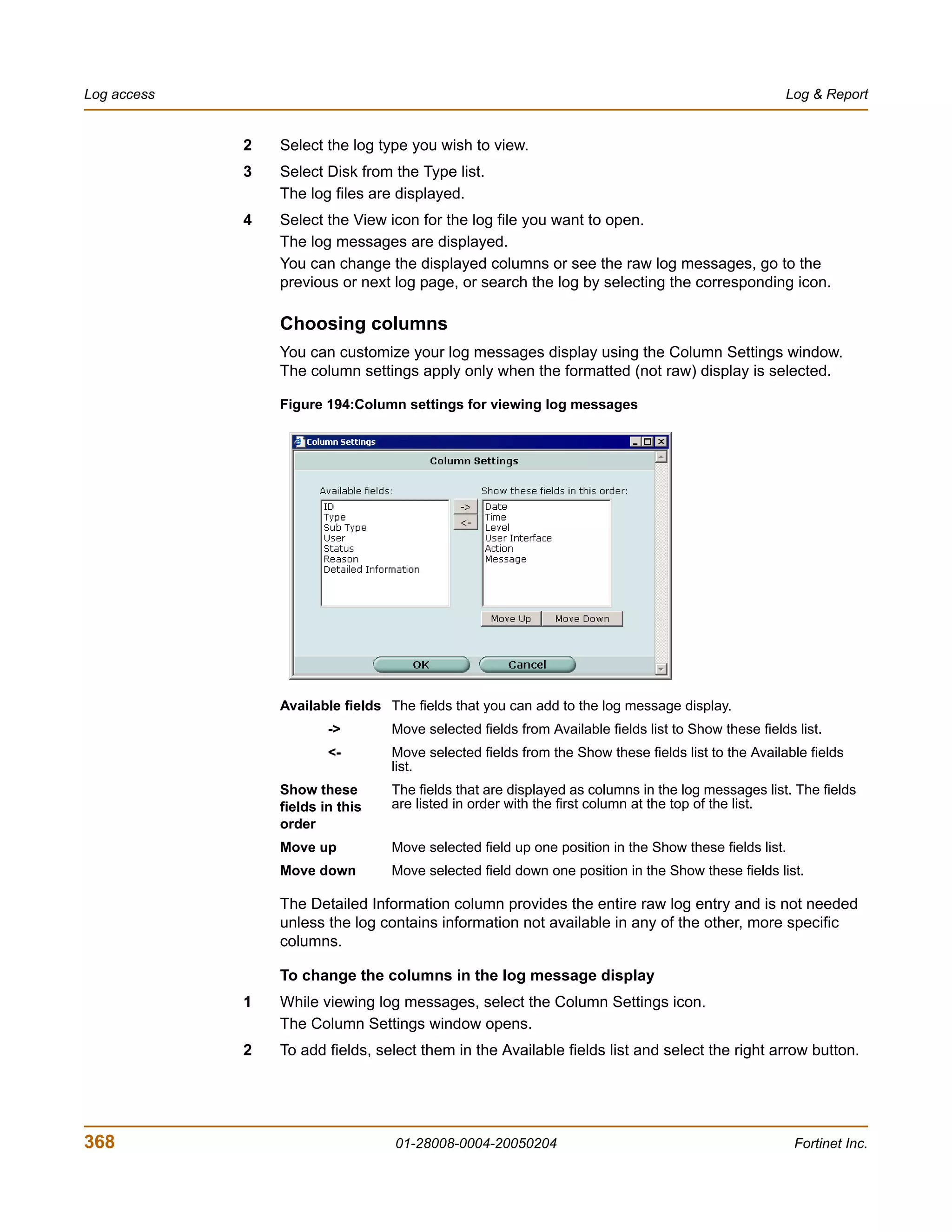
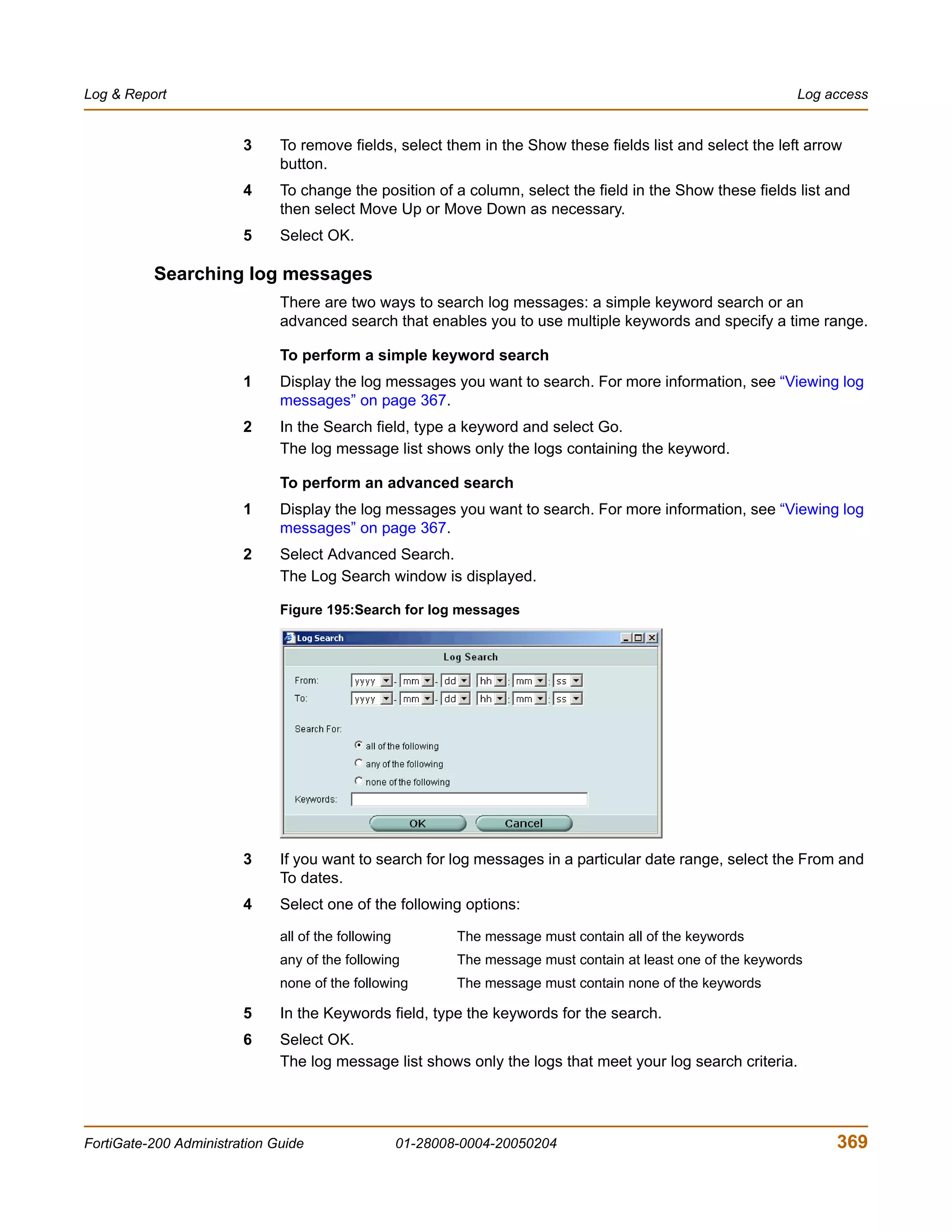
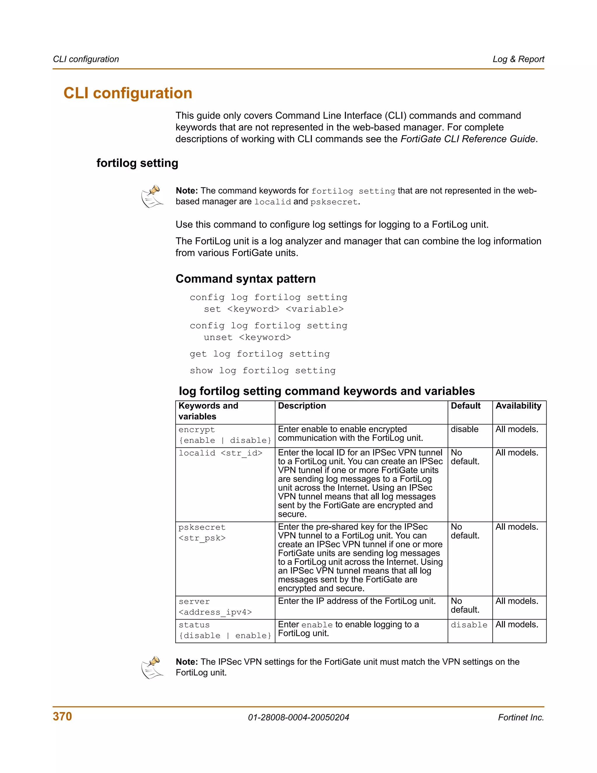
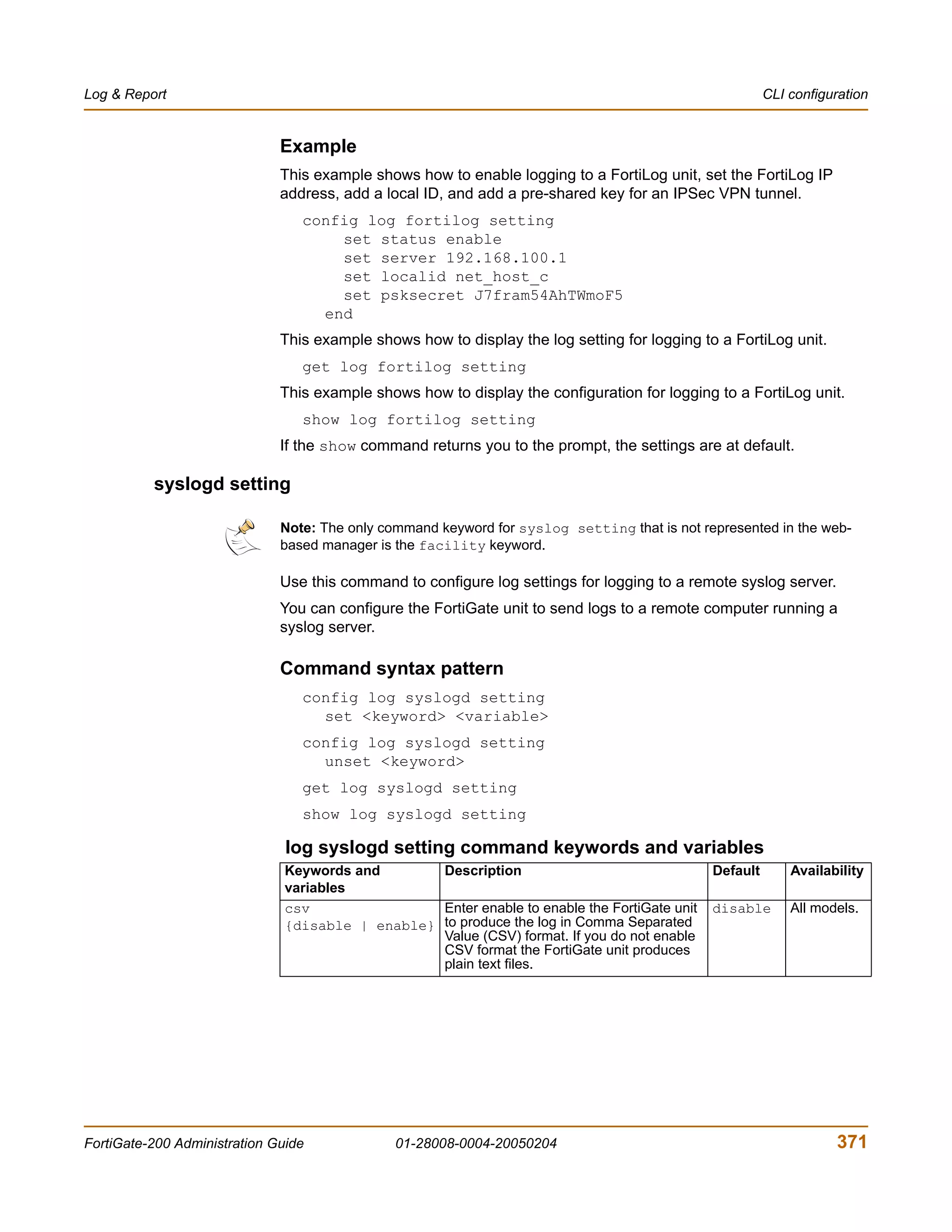
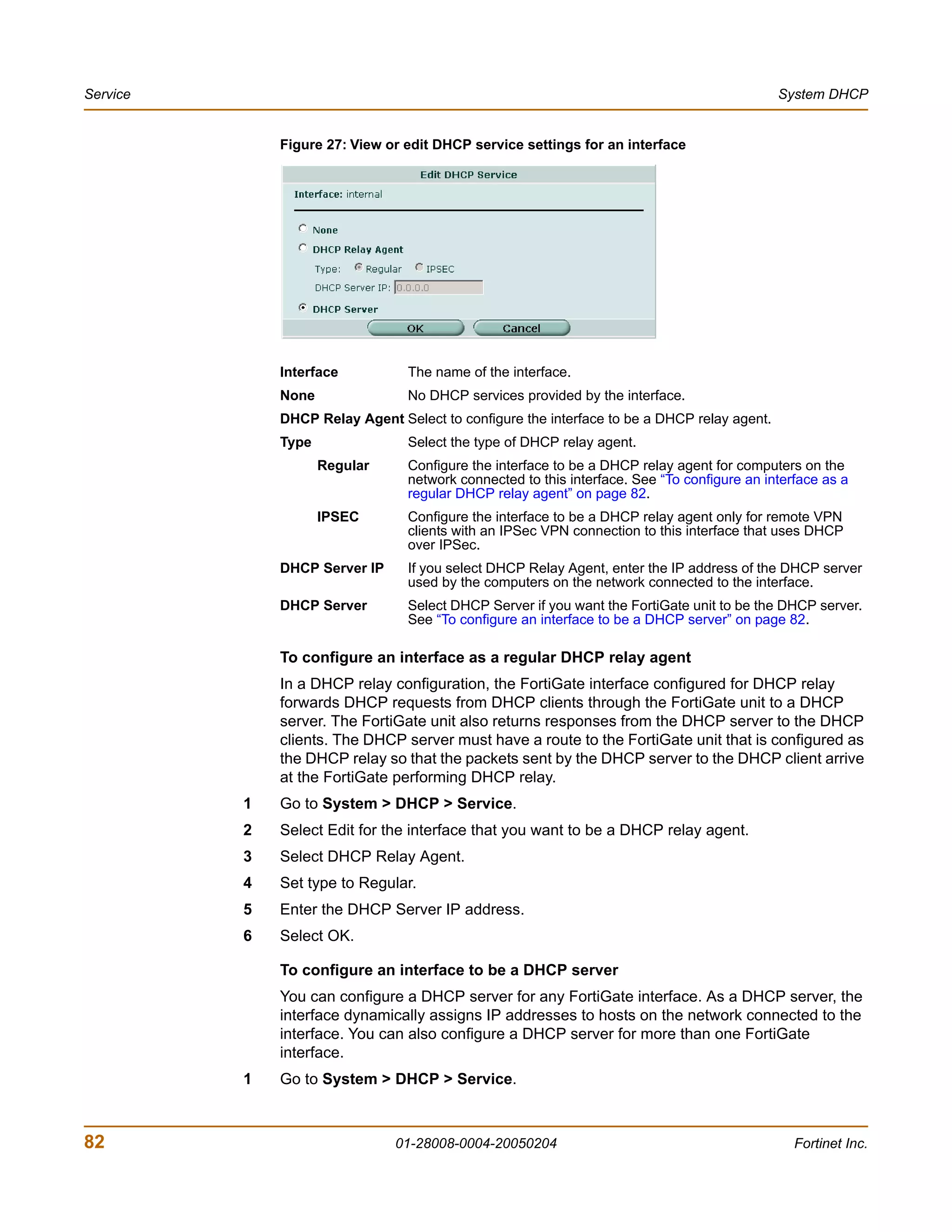
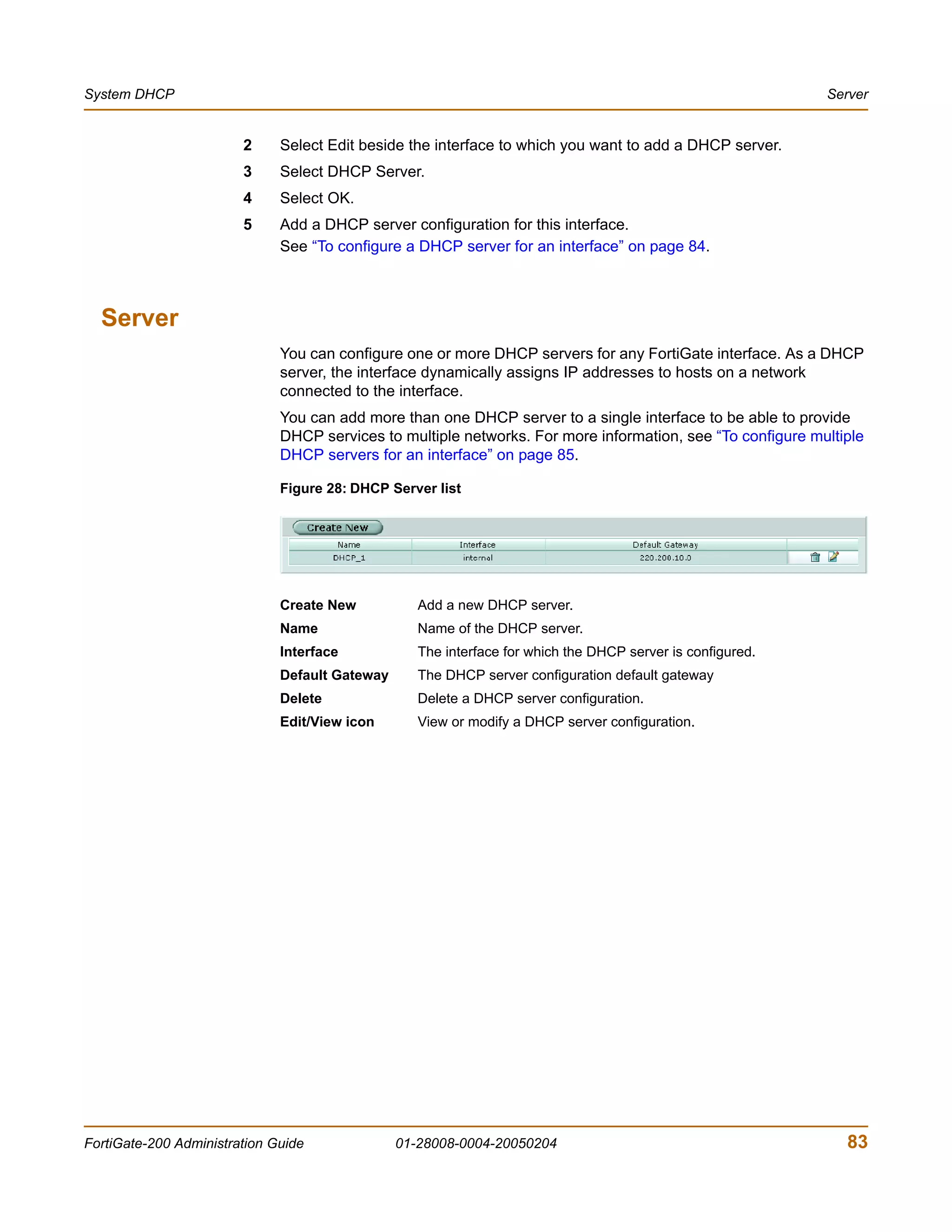
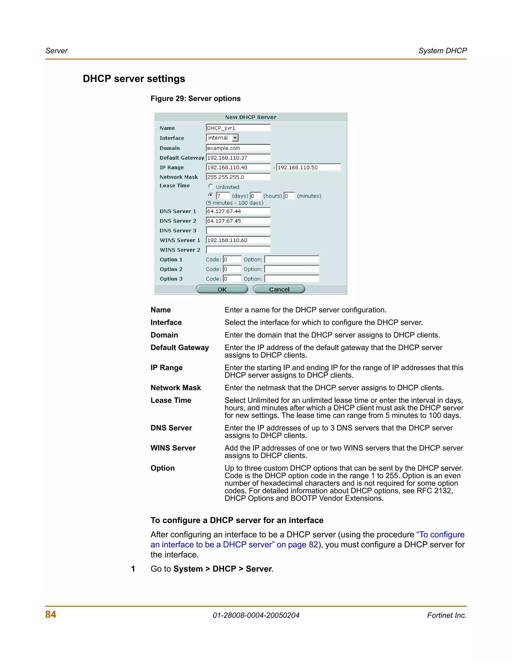
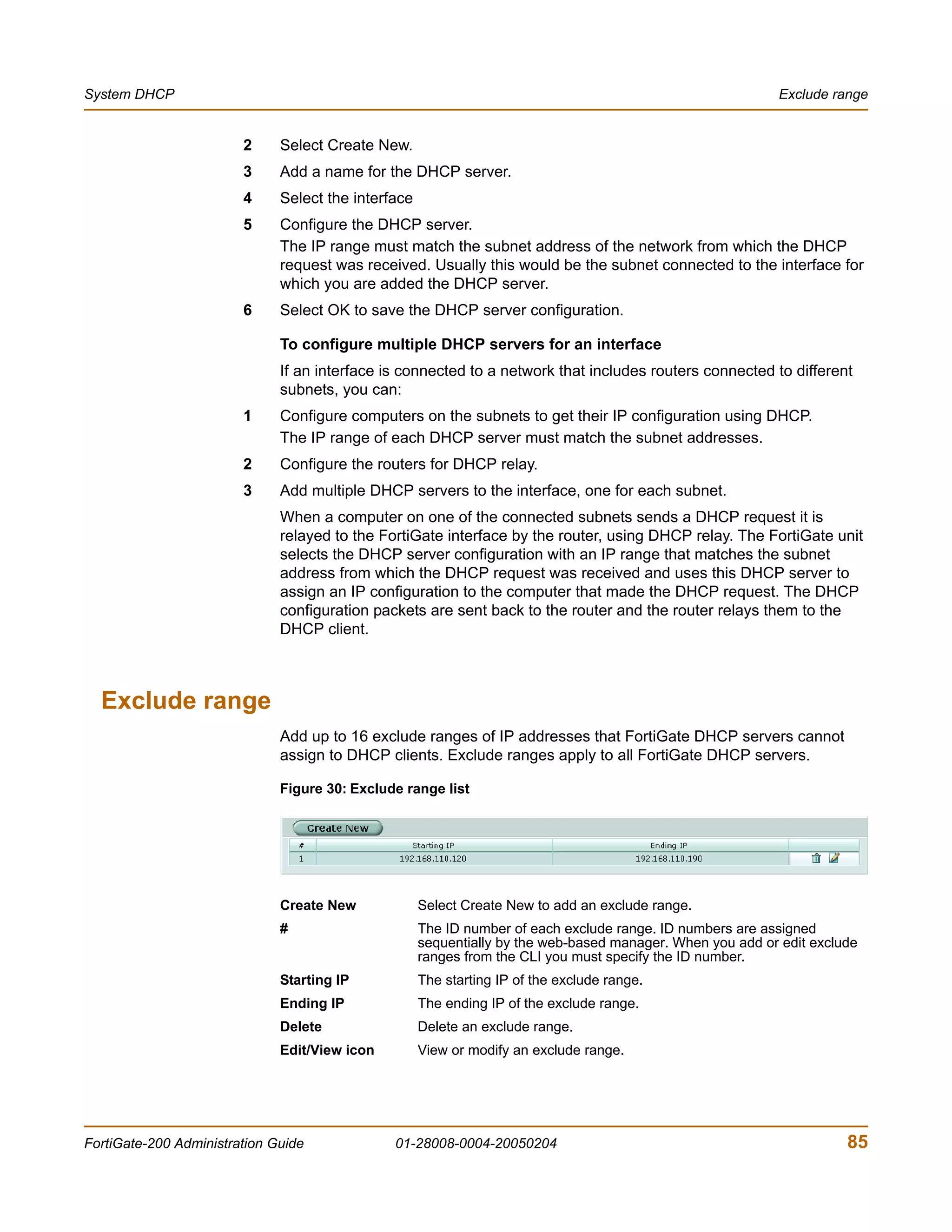
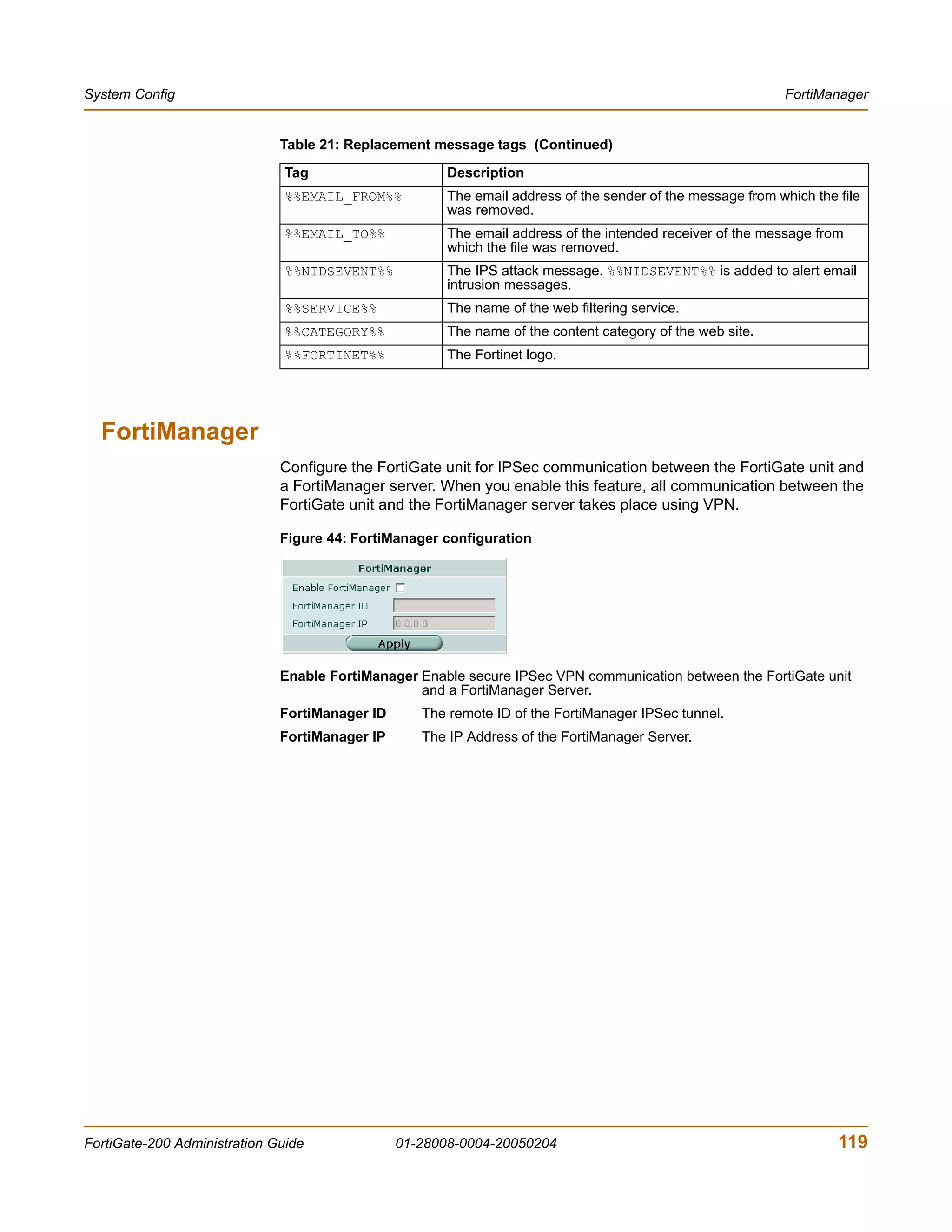
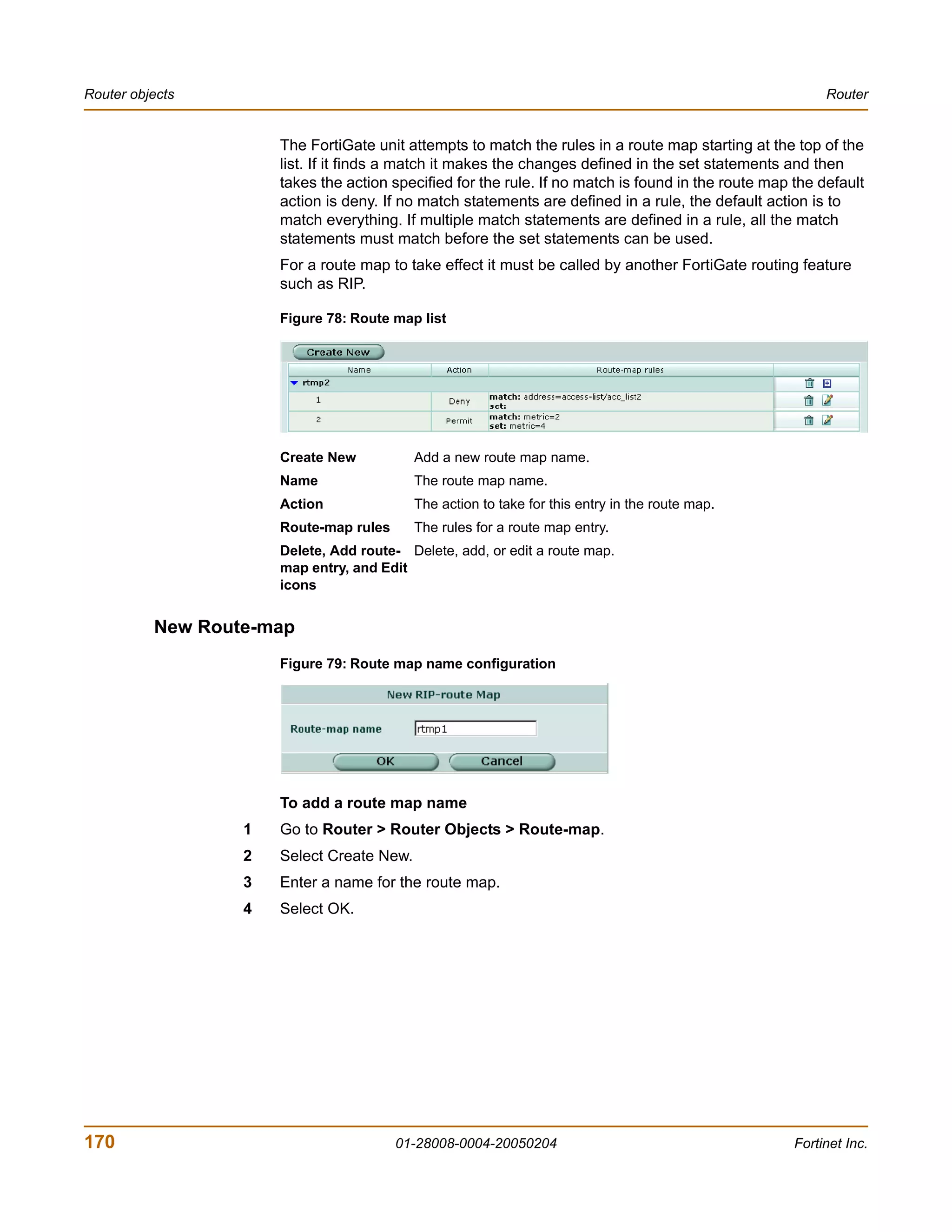
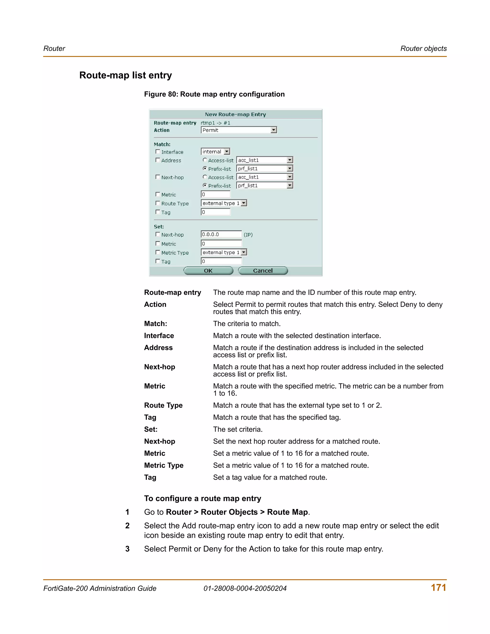
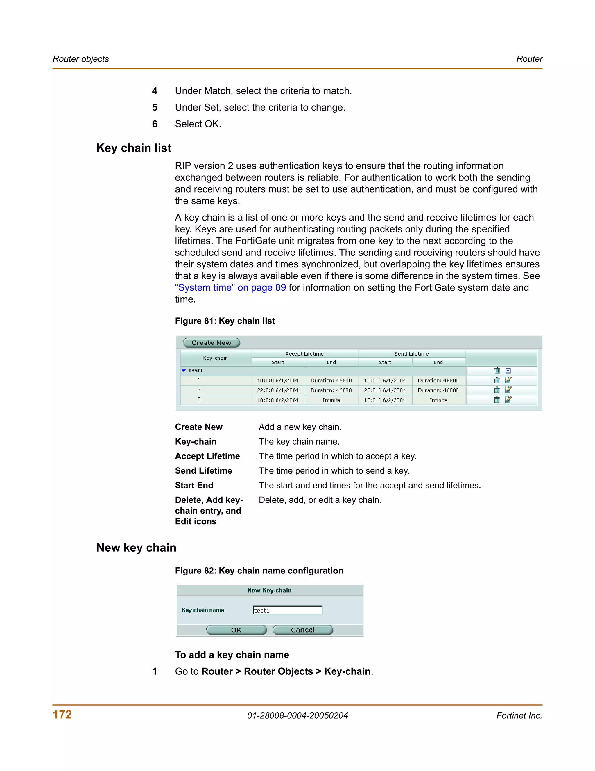
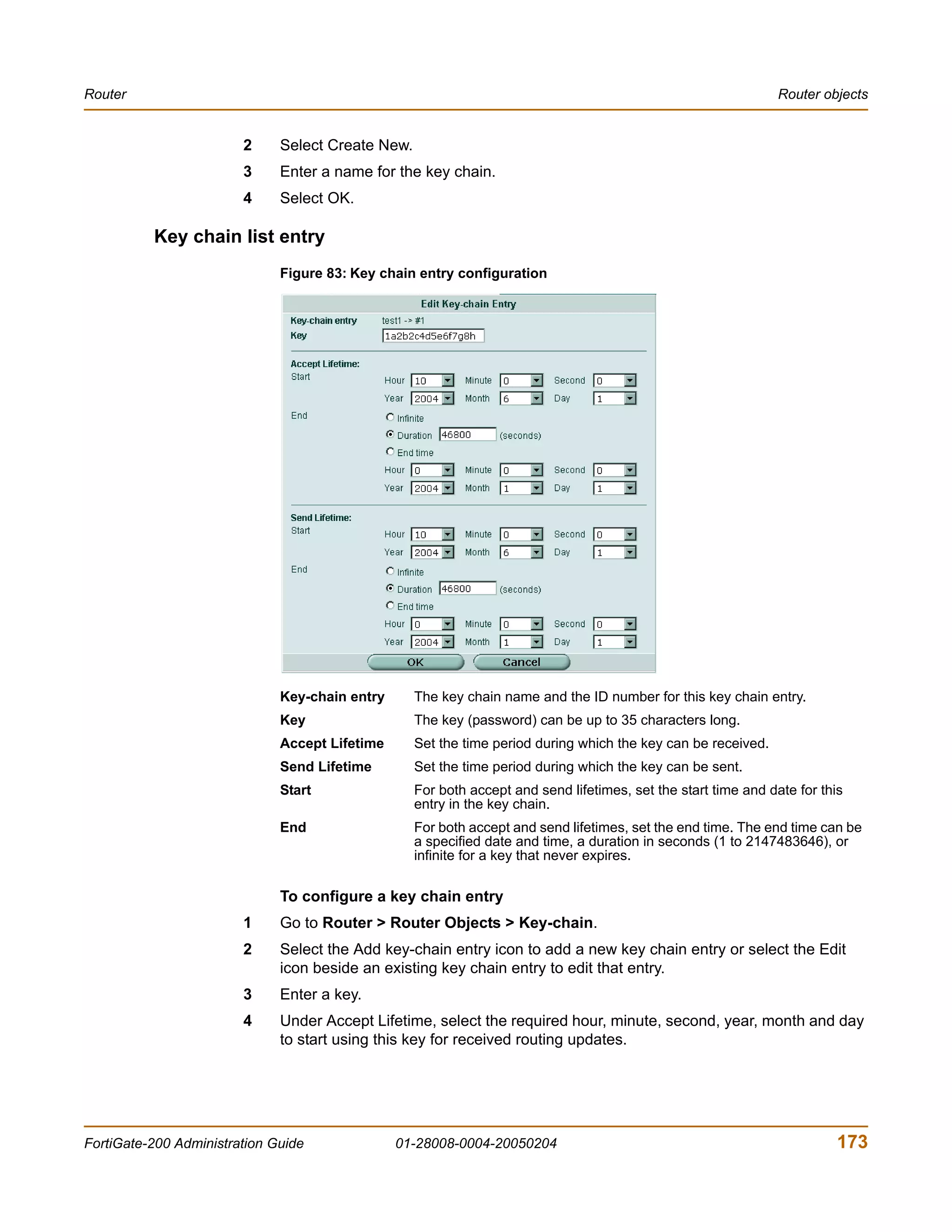
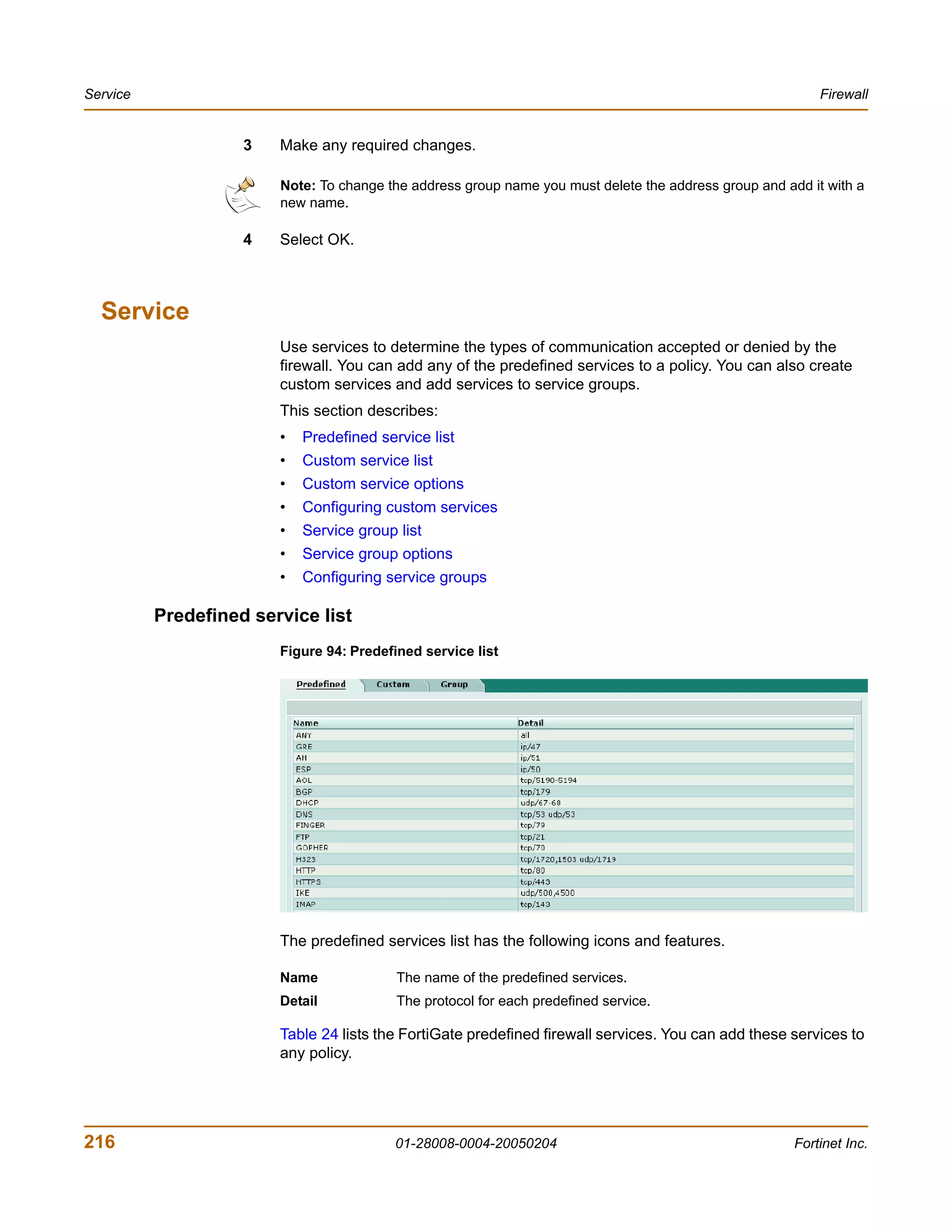
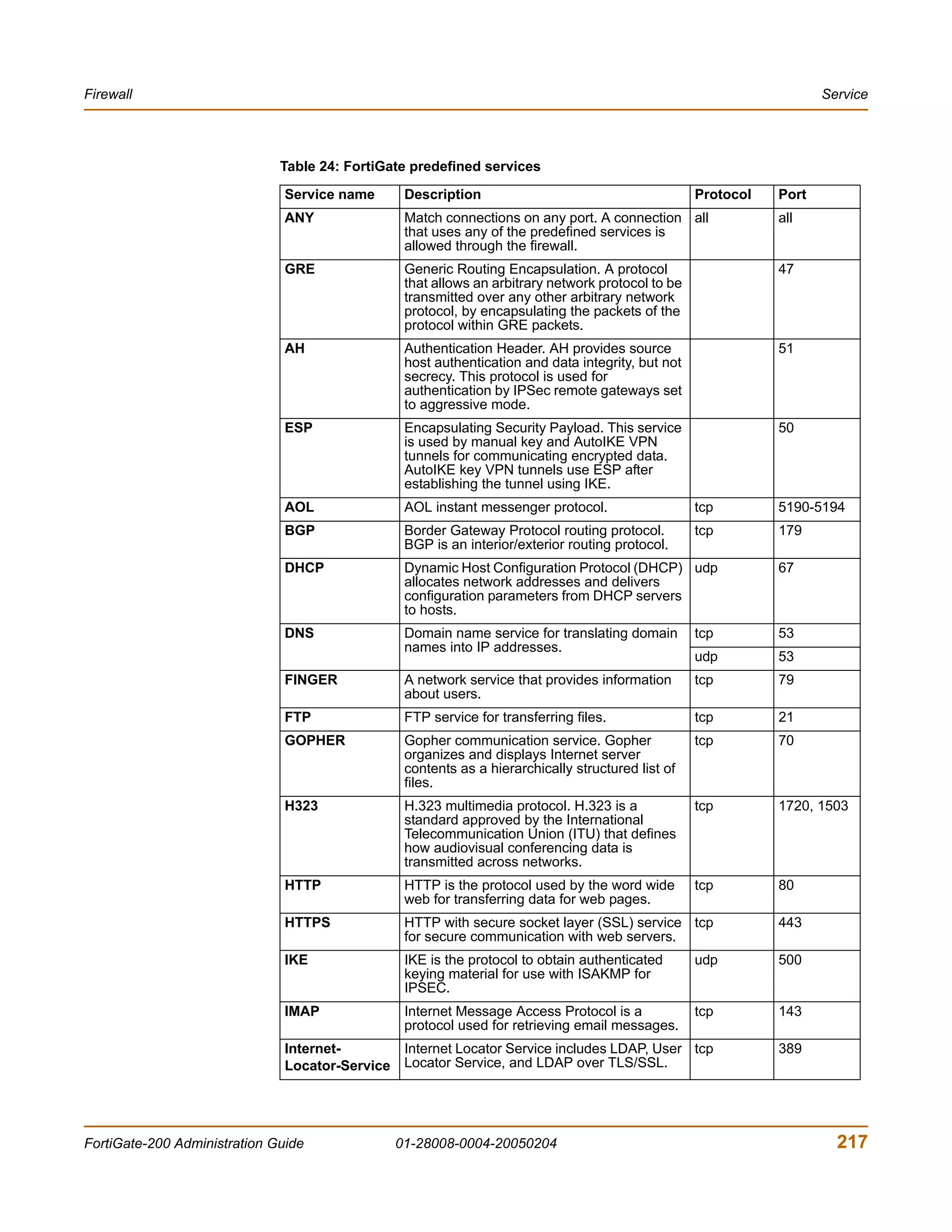
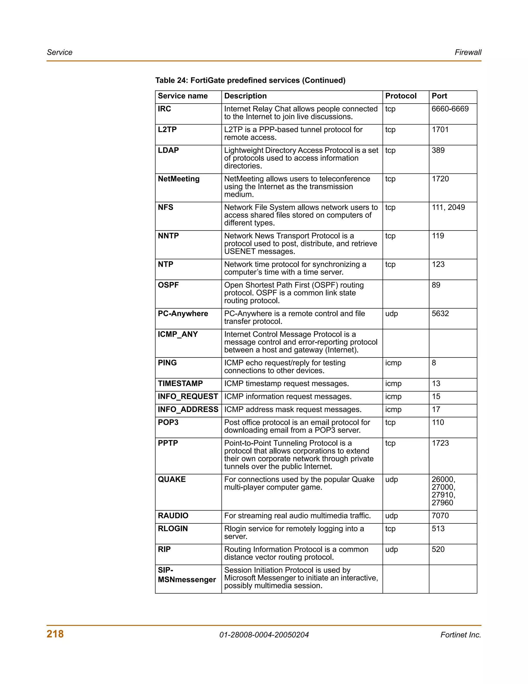
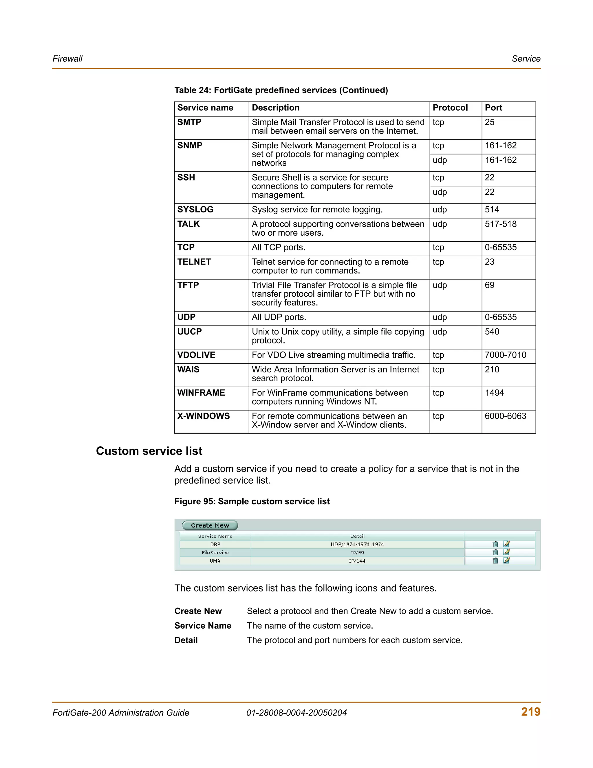
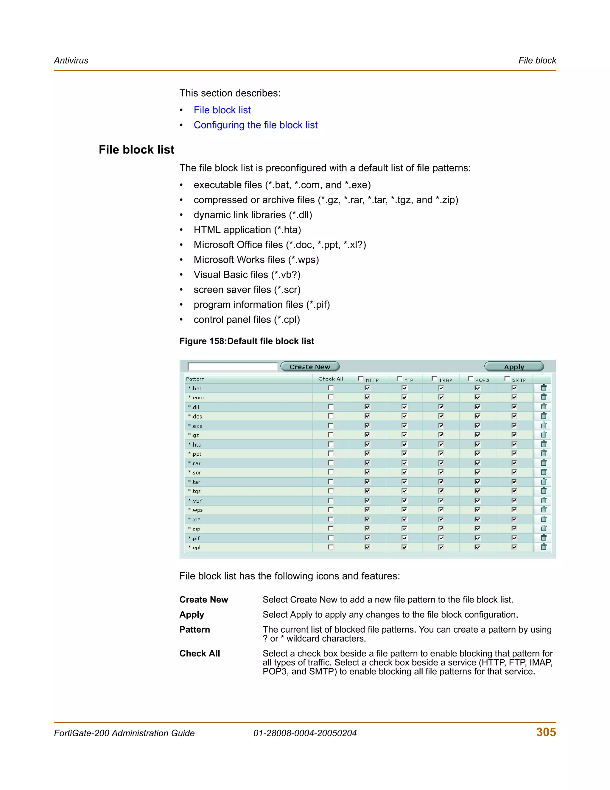
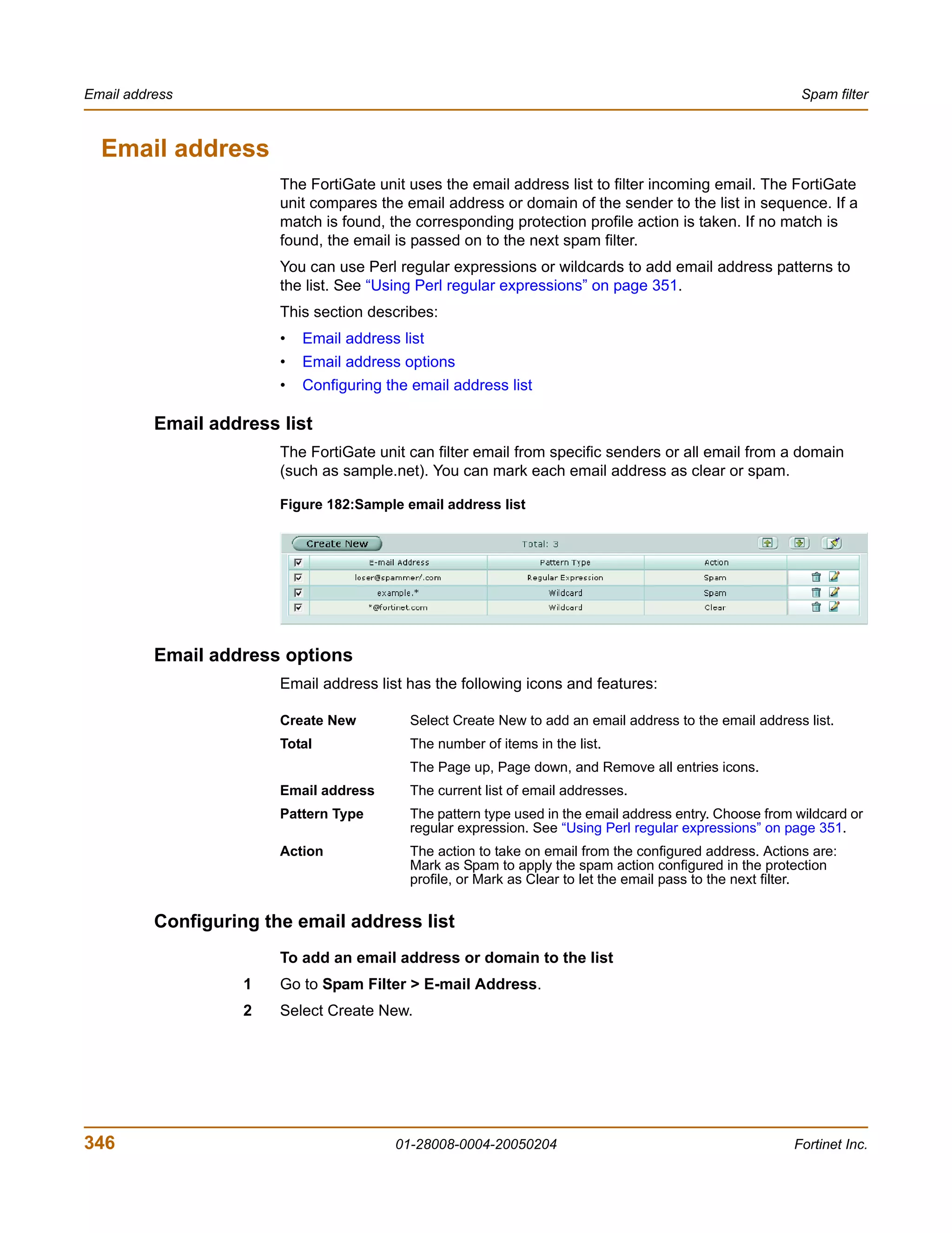
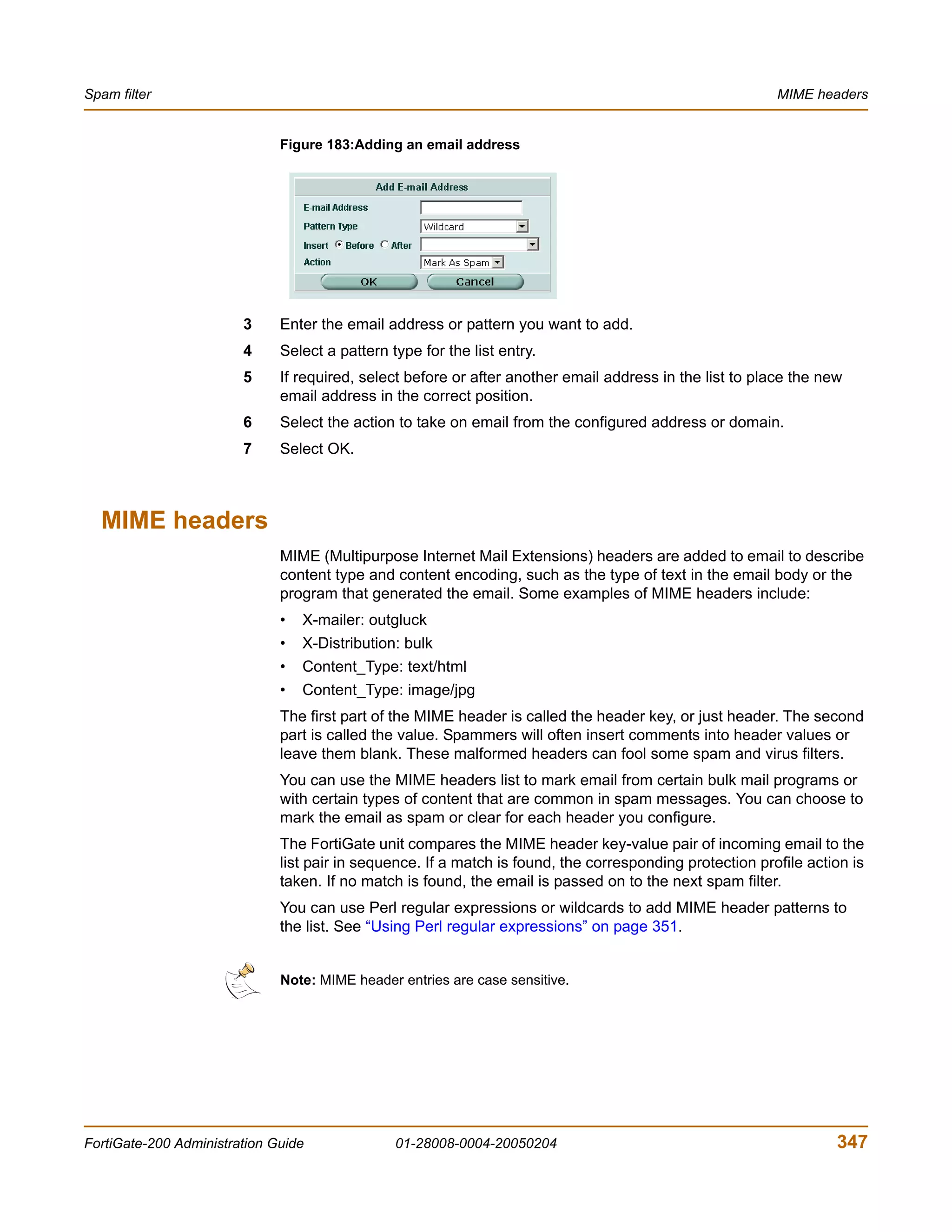
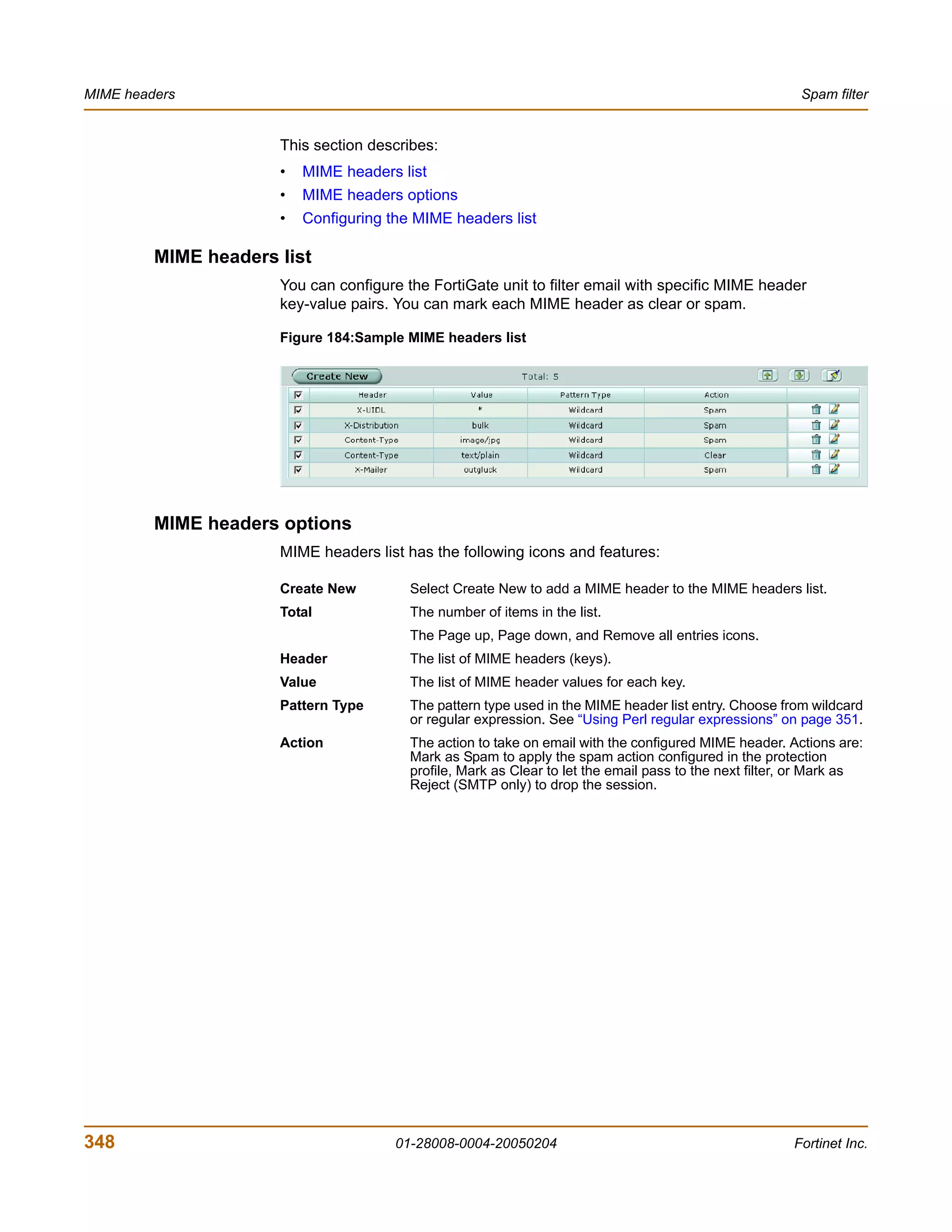
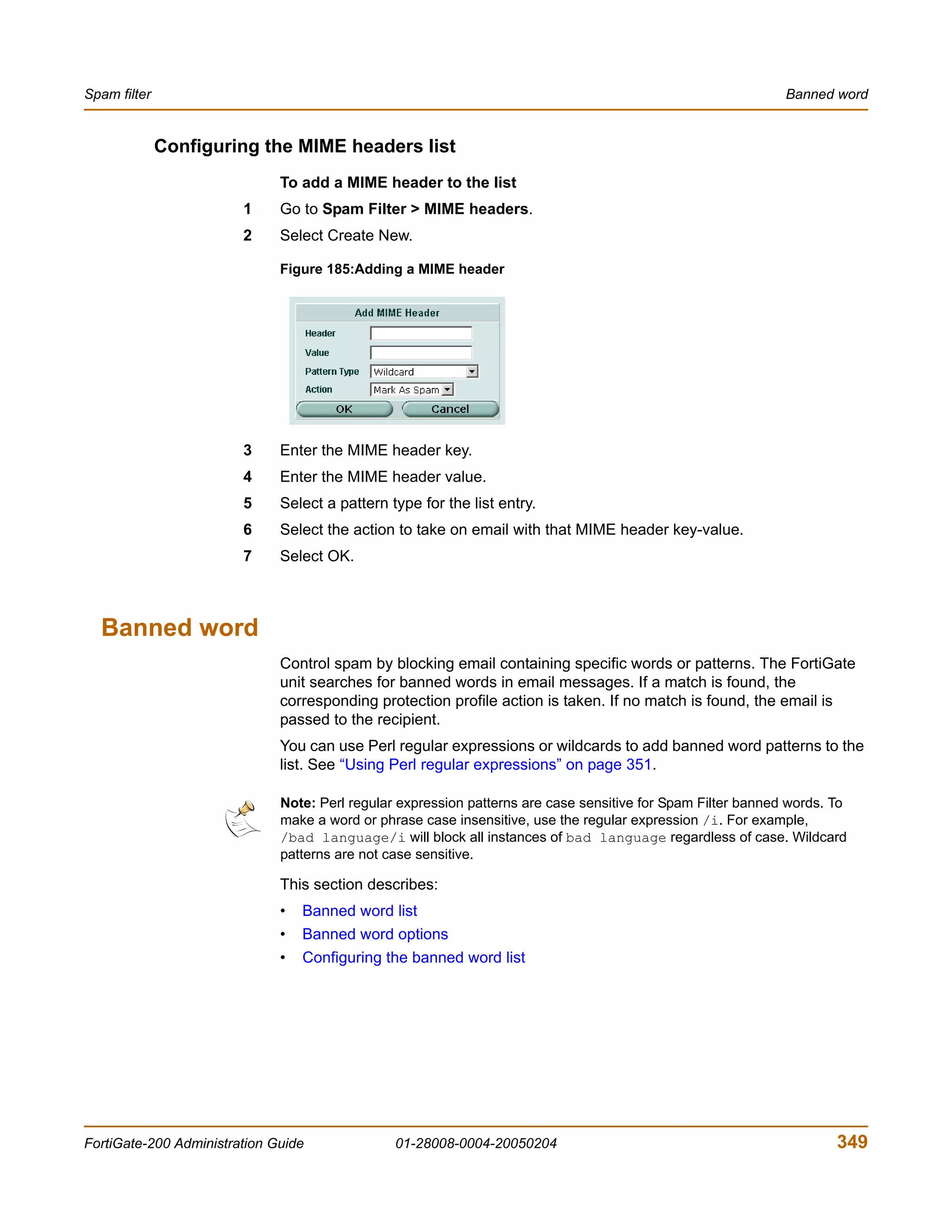
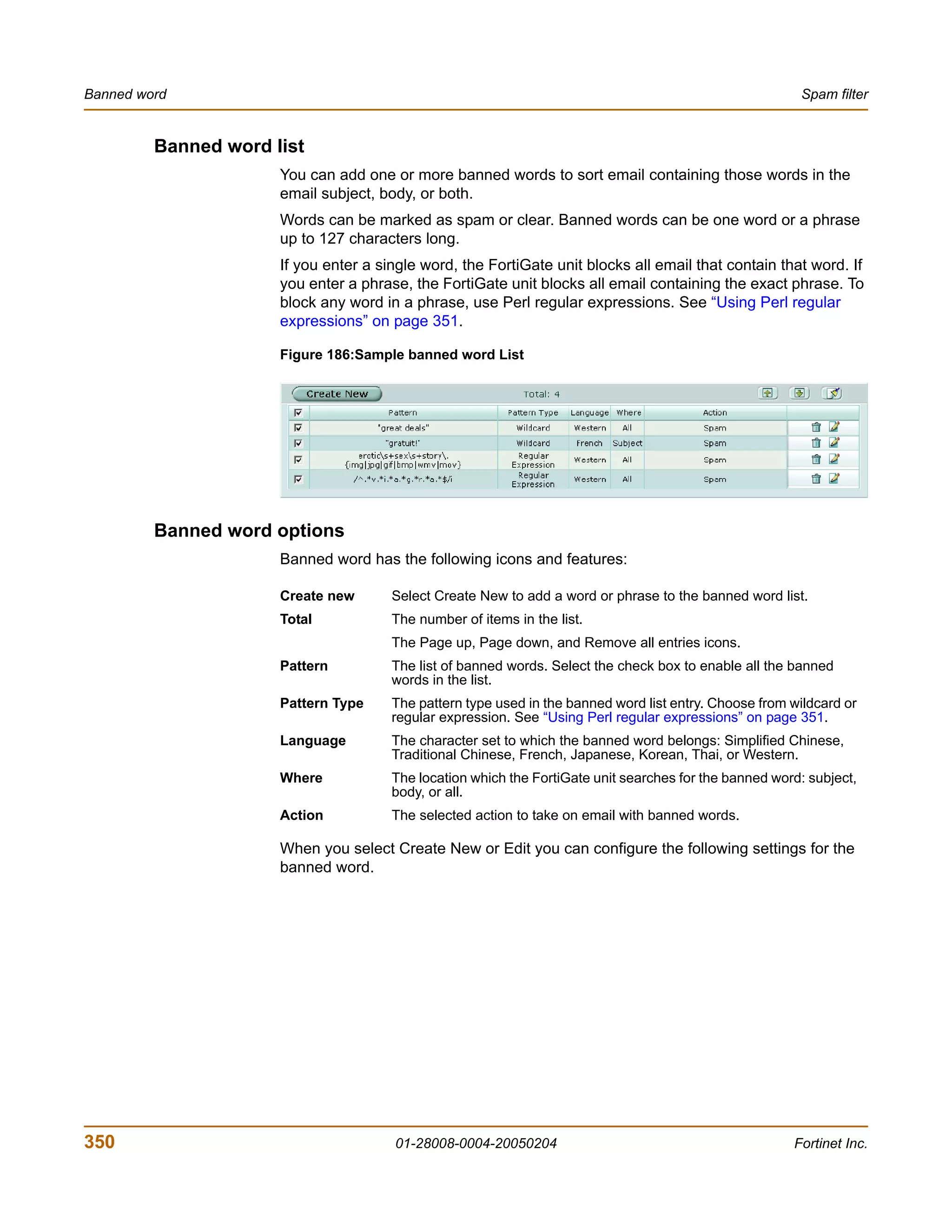
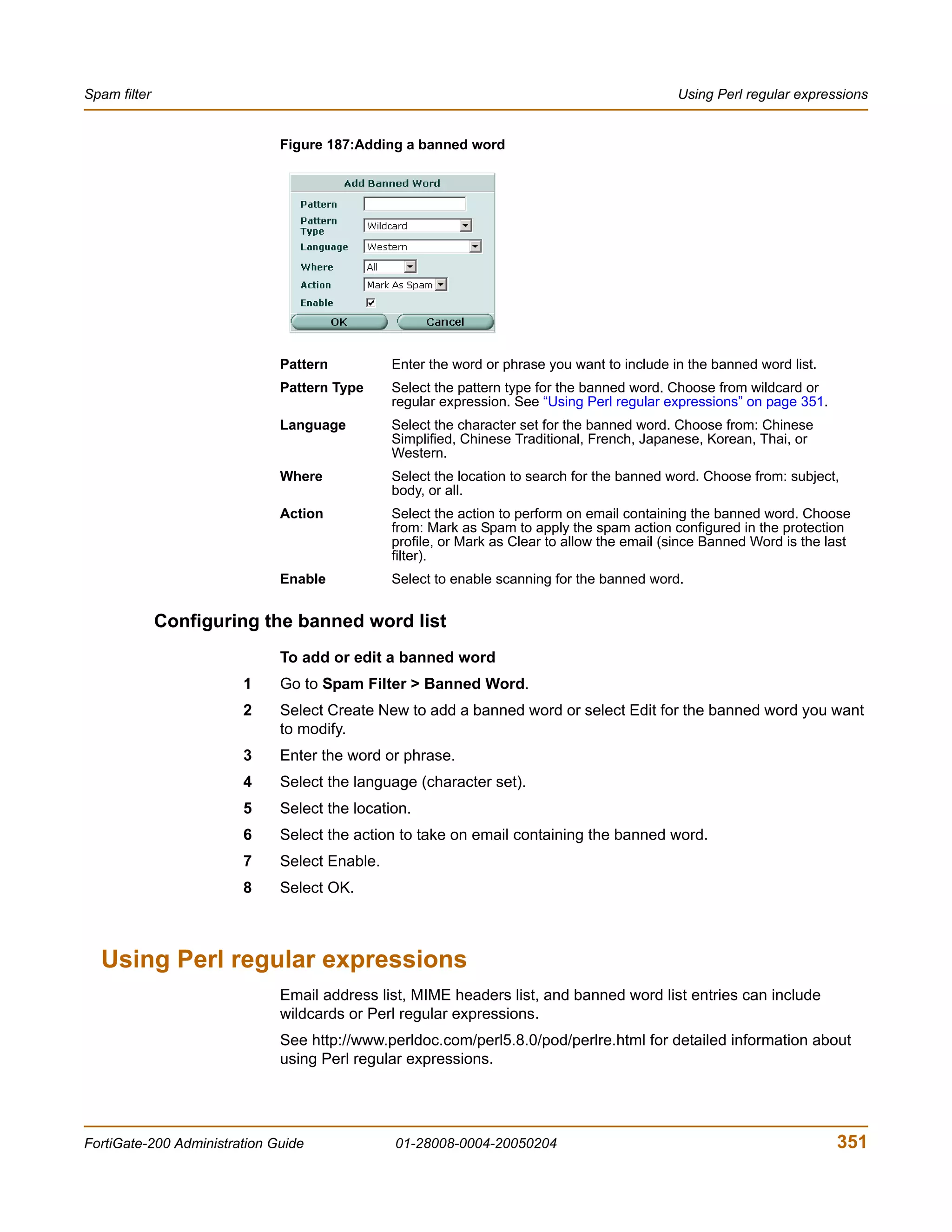
The document is the FortiGate-200 Administration Guide, version 2.80 MR8. It provides instructions for configuring and managing FortiGate-200 units including system settings, network interfaces, firewall policies, VPN configurations, and other security functions. The guide contains chapters on topics such as the web-based manager interface, system monitoring and firmware updates, network and interface settings, DHCP and routing protocols, user and device authentication, antivirus and intrusion prevention settings, and more. It aims to help administrators securely install and effectively manage FortiGate-200 devices.
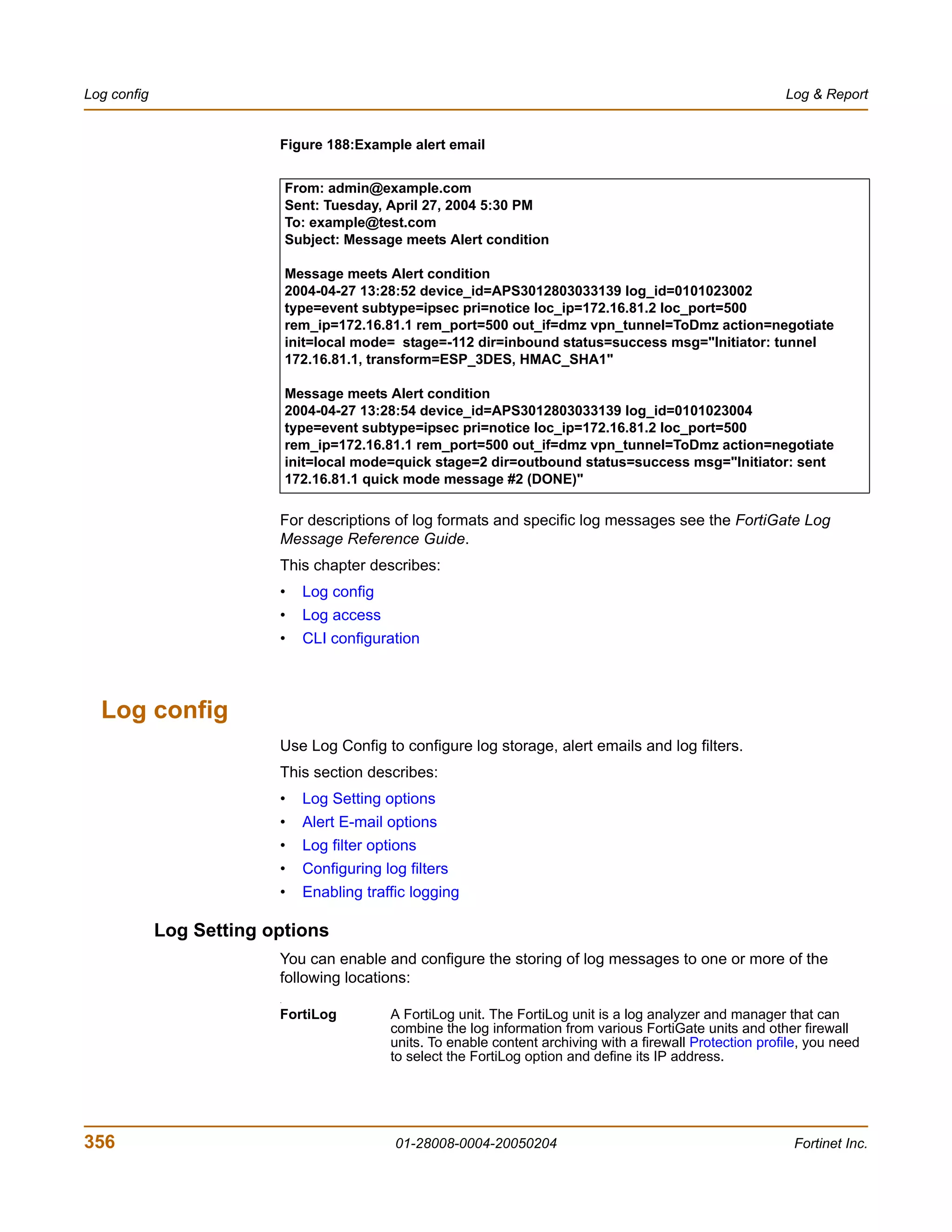
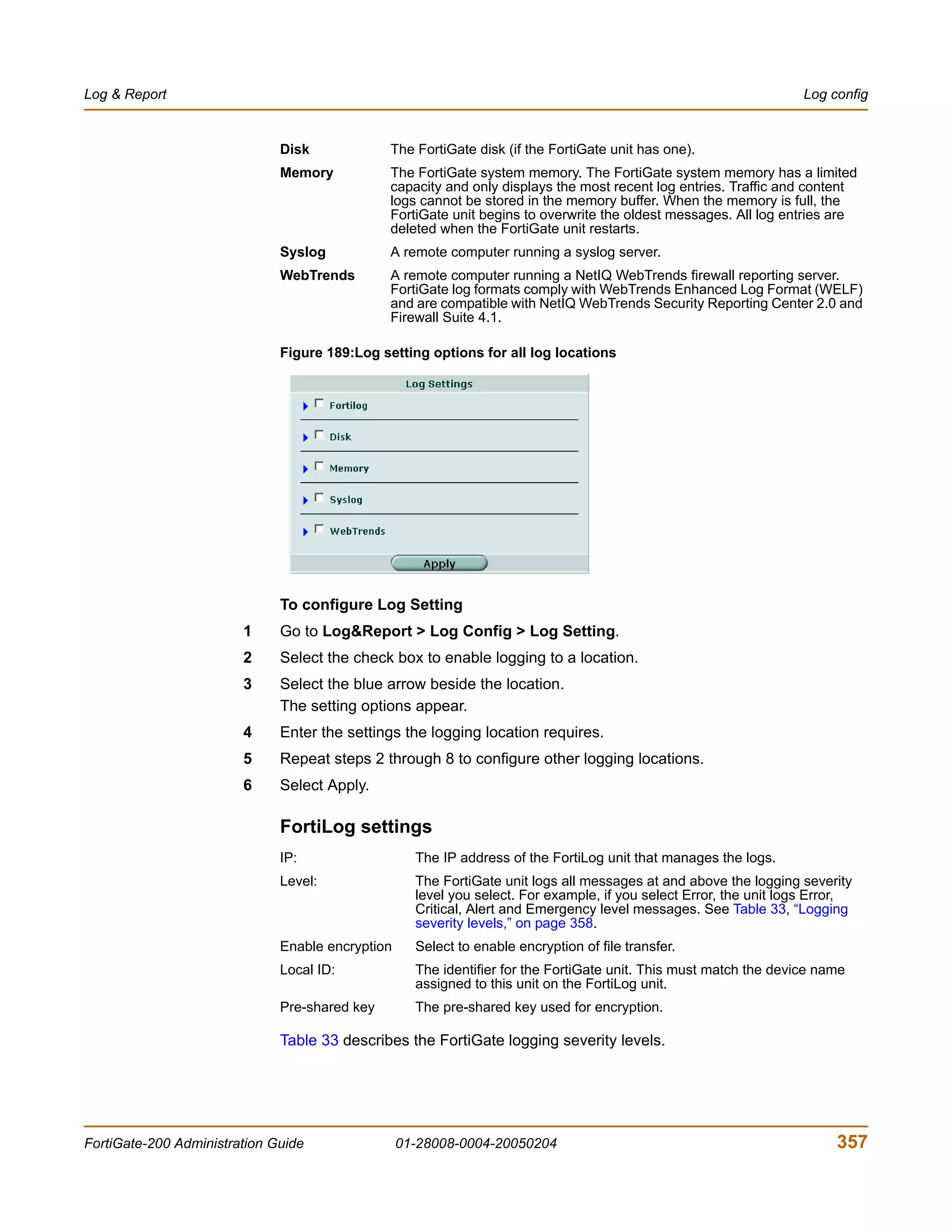
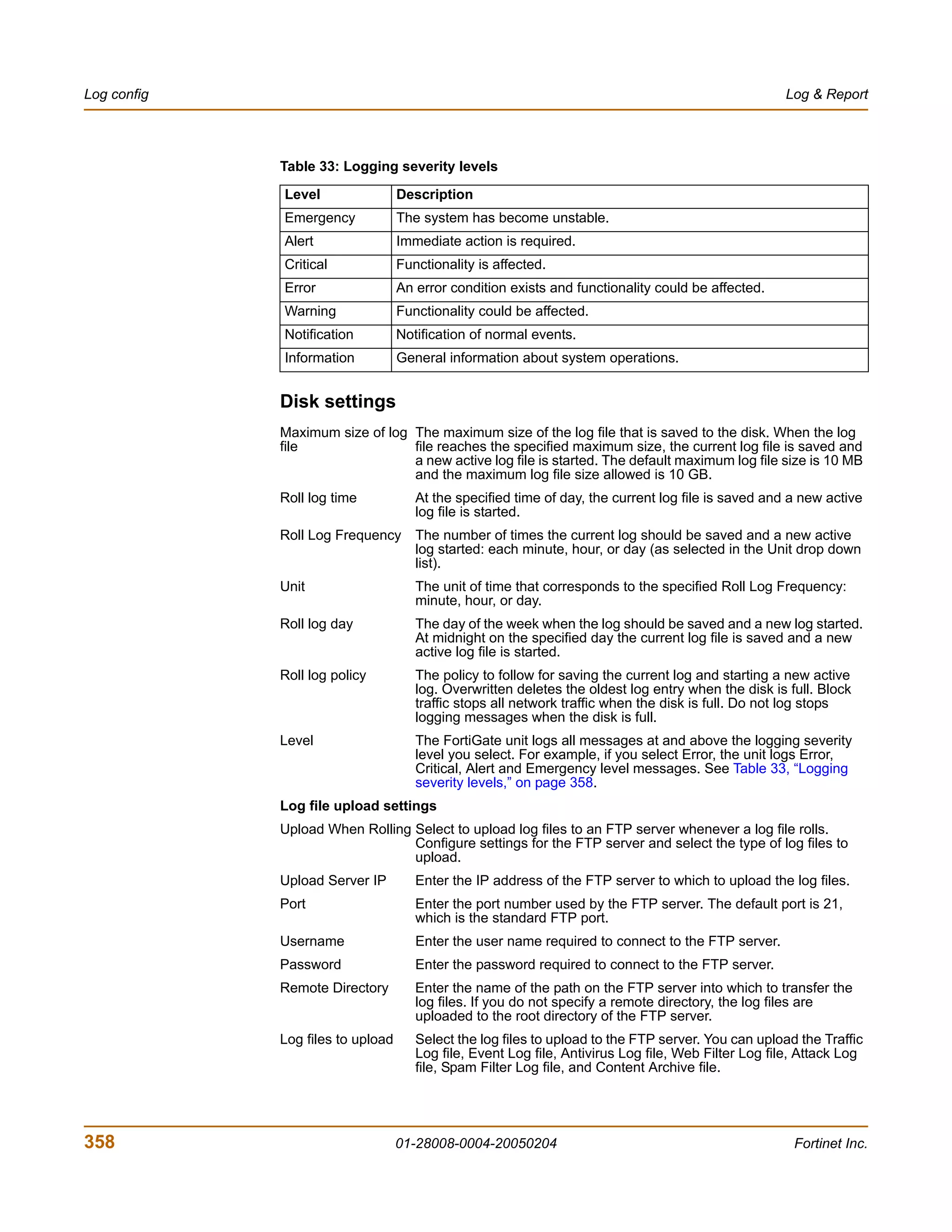
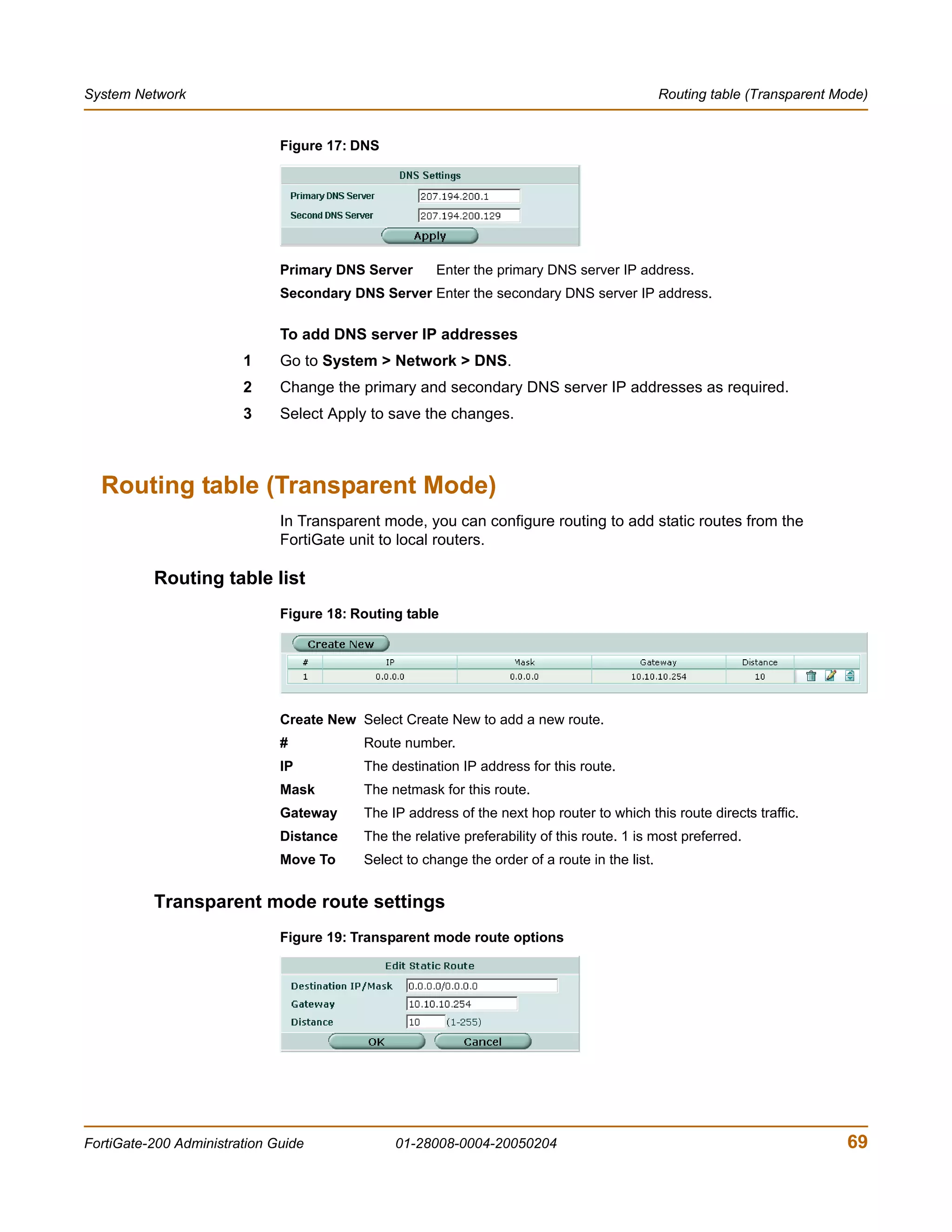
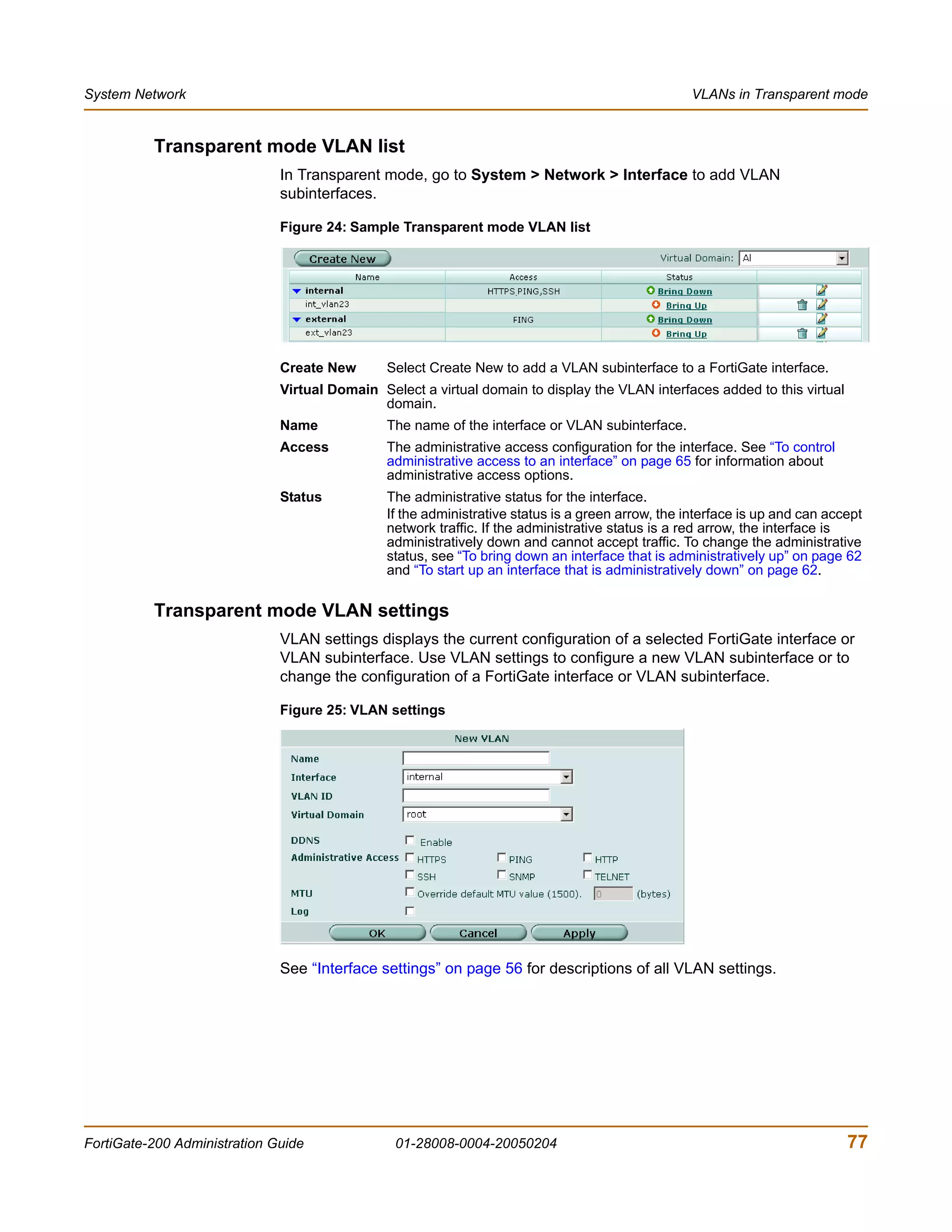
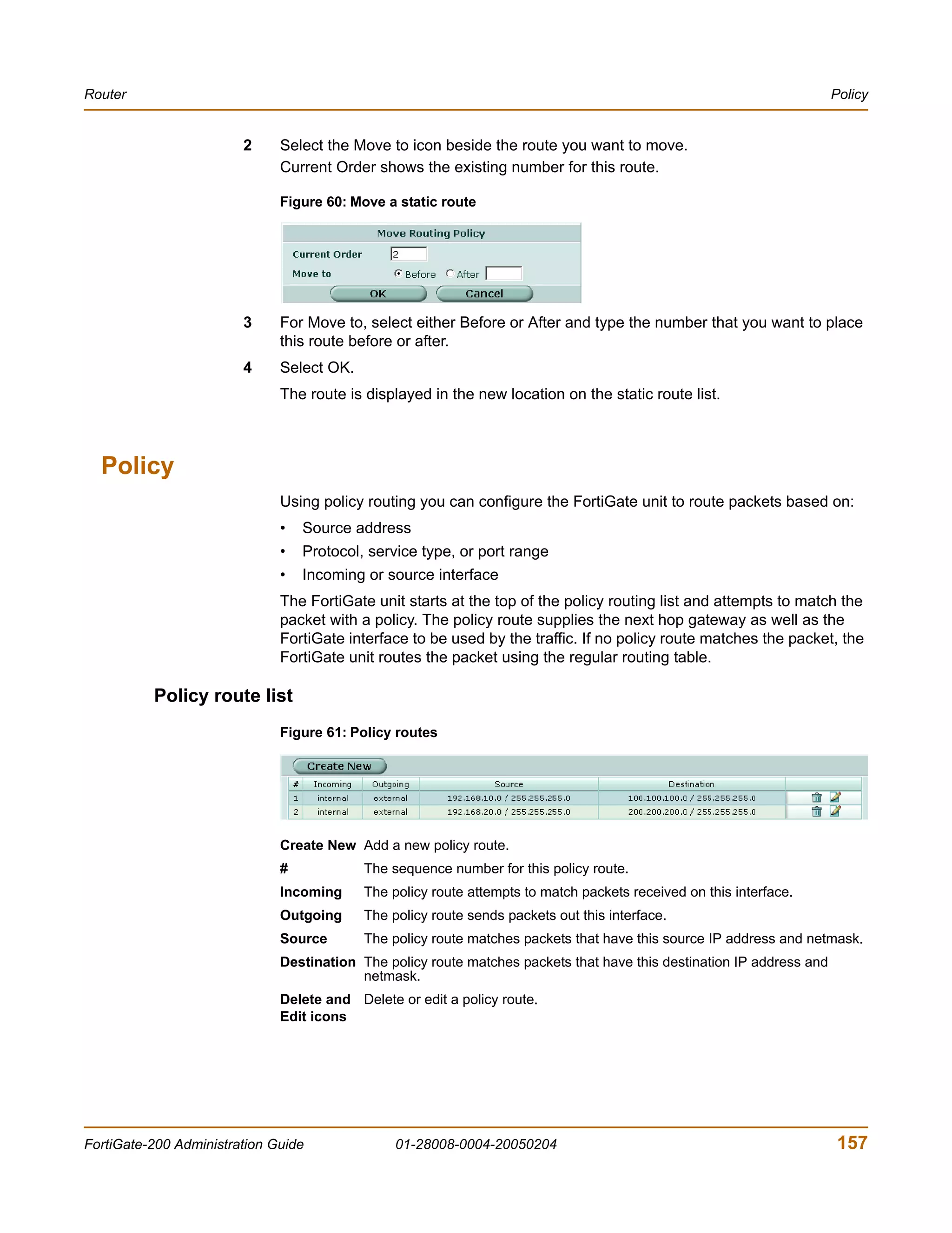
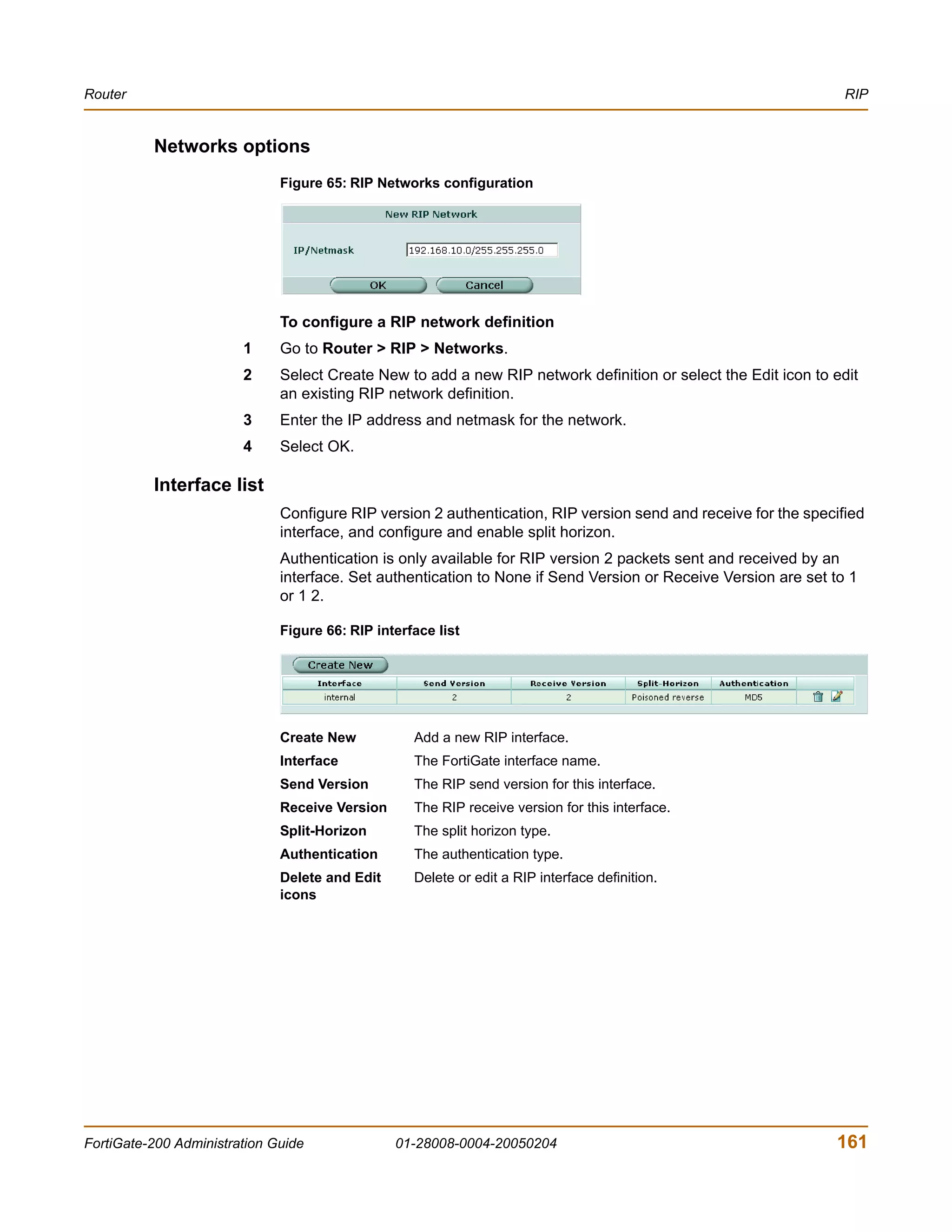
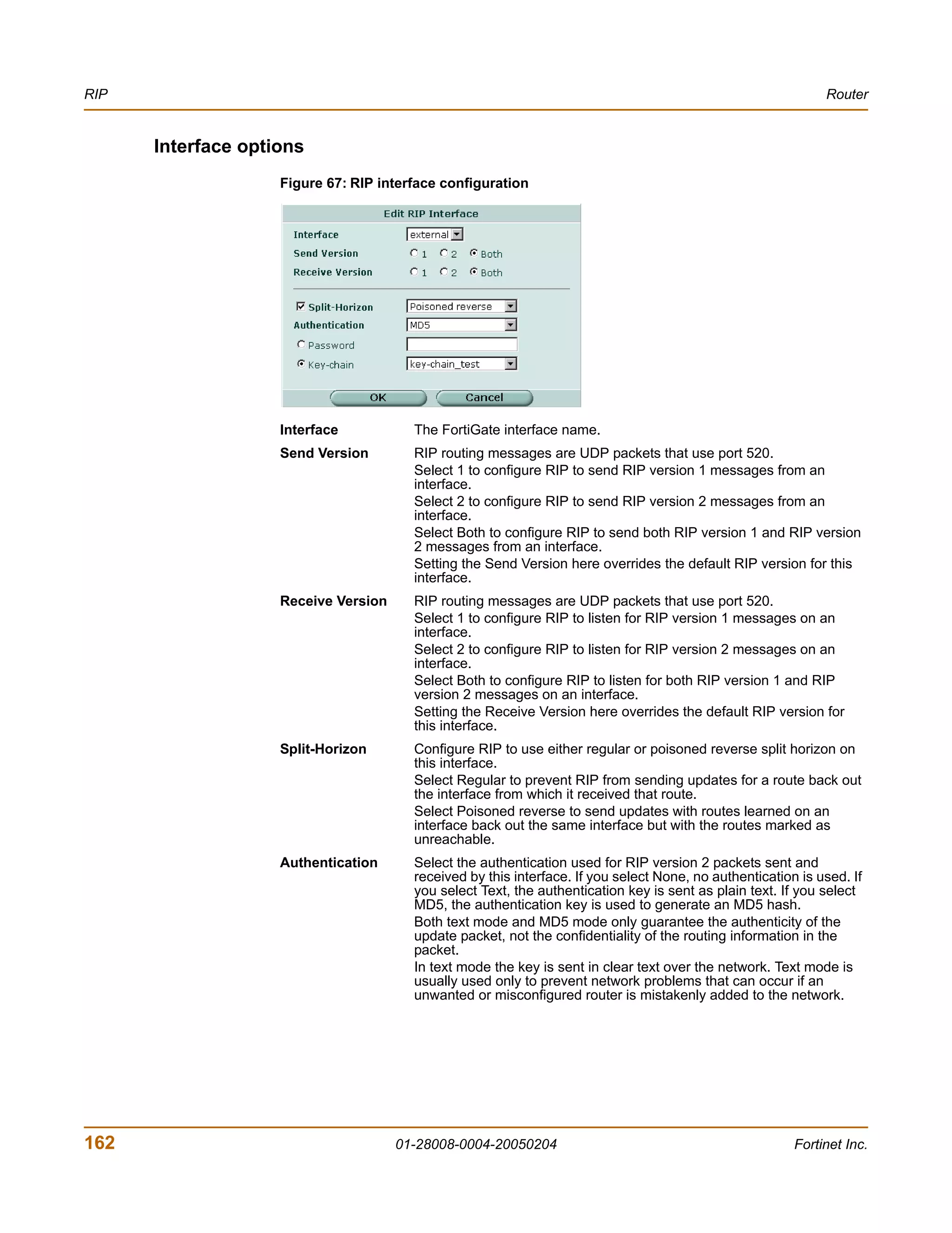
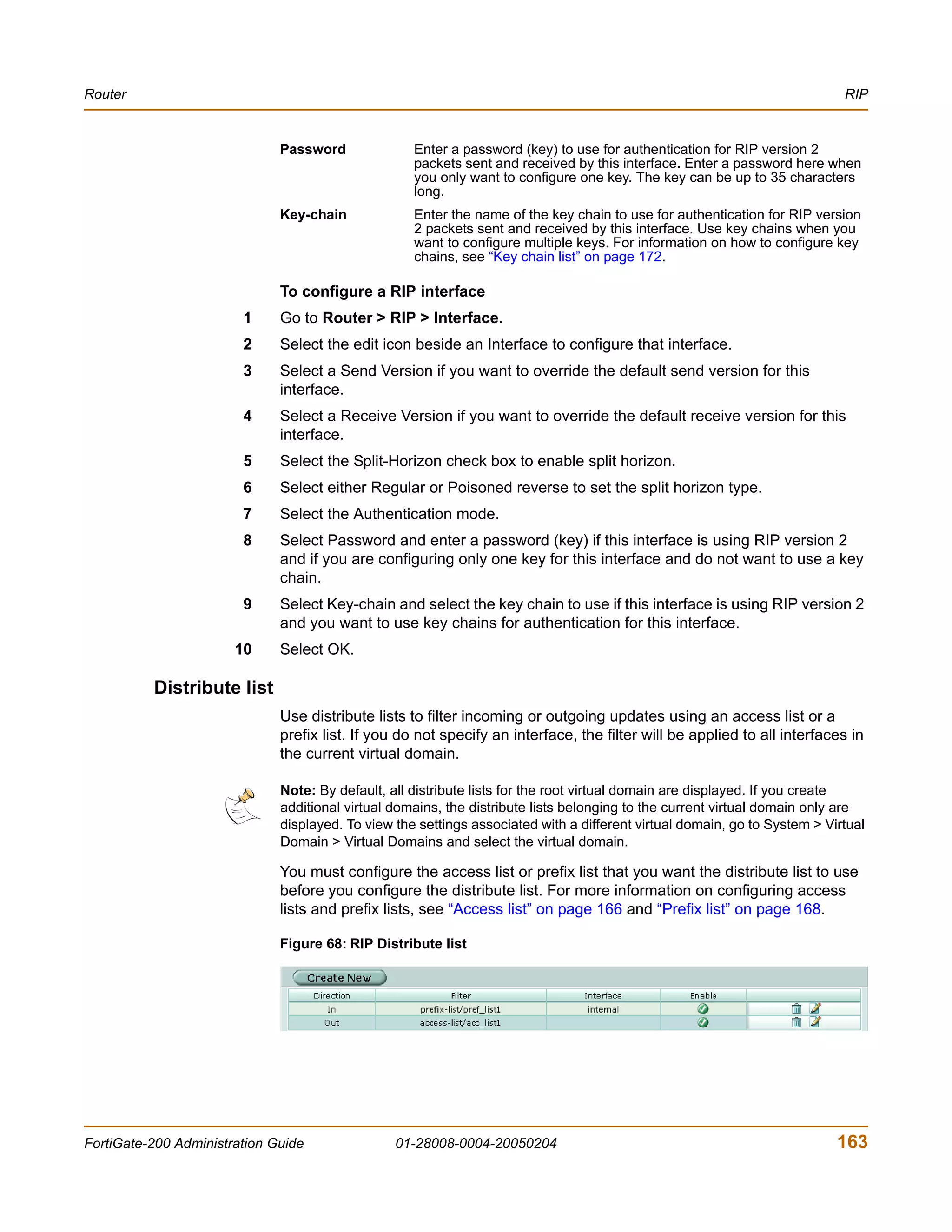
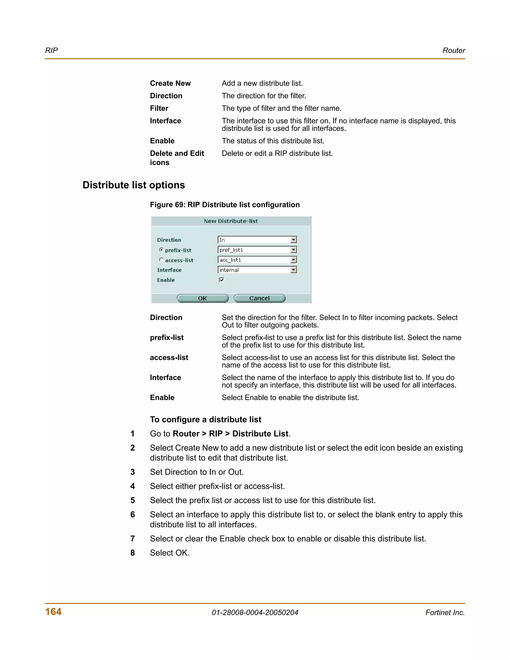
![Introduction Document conventions
You enter:
execute restore config myfile.bak
<xxx_str> indicates an ASCII string that does not contain new-lines or carriage
returns.
<xxx_integer> indicates an integer string that is a decimal (base 10) number.
<xxx_octet> indicates a hexadecimal string that uses the digits 0-9 and letters
A-F.
<xxx_ipv4> indicates a dotted decimal IPv4 address.
<xxx_v4mask> indicates a dotted decimal IPv4 netmask.
<xxx_ipv4mask> indicates a dotted decimal IPv4 address followed by a dotted
decimal IPv4 netmask.
<xxx_ipv6> indicates a dotted decimal IPv6 address.
<xxx_v6mask> indicates a dotted decimal IPv6 netmask.
<xxx_ipv6mask> indicates a dotted decimal IPv6 address followed by a dotted
decimal IPv6 netmask.
• Vertical bar and curly brackets {|} to separate alternative, mutually exclusive
required keywords.
For example:
set opmode {nat | transparent}
You can enter set opmode nat or set opmode transparent.
• Square brackets [ ] to indicate that a keyword or variable is optional.
For example:
show system interface [<name_str>]
To show the settings for all interfaces, you can enter show system interface.
To show the settings for the internal interface, you can enter show system
interface internal.
• A space to separate options that can be entered in any combination and must be
separated by spaces.
For example:
set allowaccess {ping https ssh snmp http telnet}
You can enter any of the following:
set allowaccess ping
set allowaccess ping https ssh
set allowaccess https ping ssh
set allowaccess snmp
In most cases to make changes to lists that contain options separated by spaces,
you need to retype the whole list including all the options you want to apply and
excluding all the options you want to remove.
FortiGate-200 Administration Guide 01-28008-0004-20050204 21](https://image.slidesharecdn.com/01-28008-0004-20050204fortigate-200administrationguide-121225111736-phpapp02/75/01-28008-0004-20050204-forti-gate-200_administration-guide-21-2048.jpg)
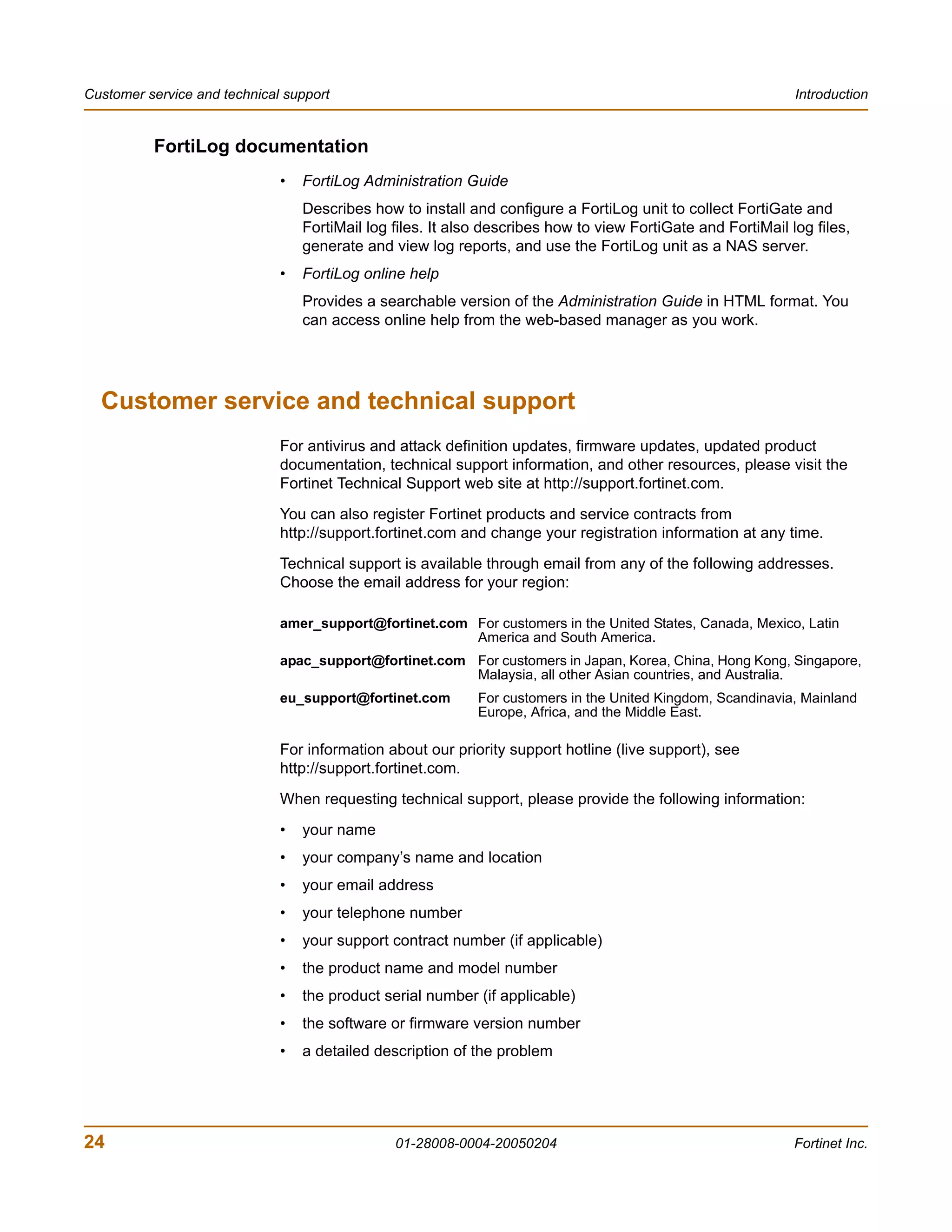

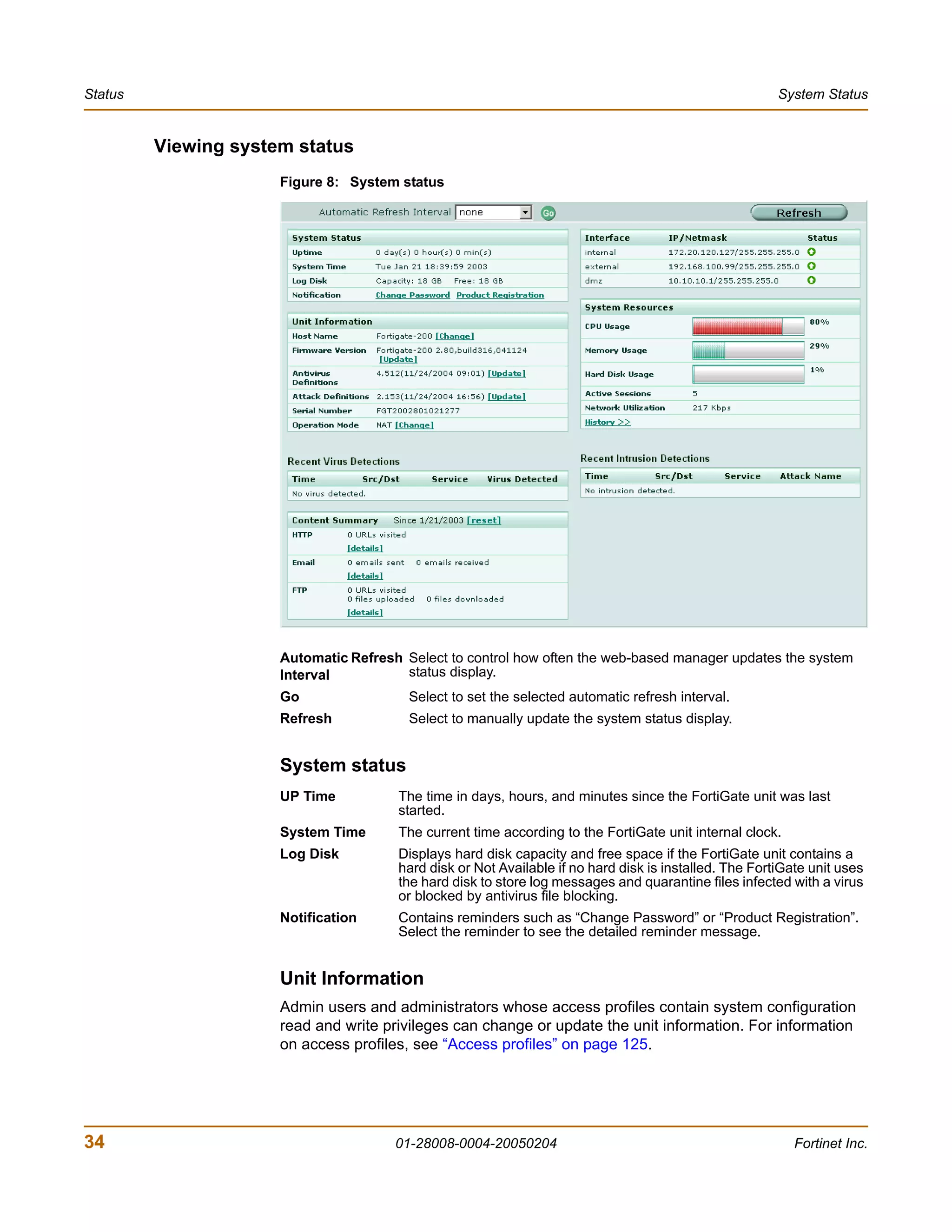
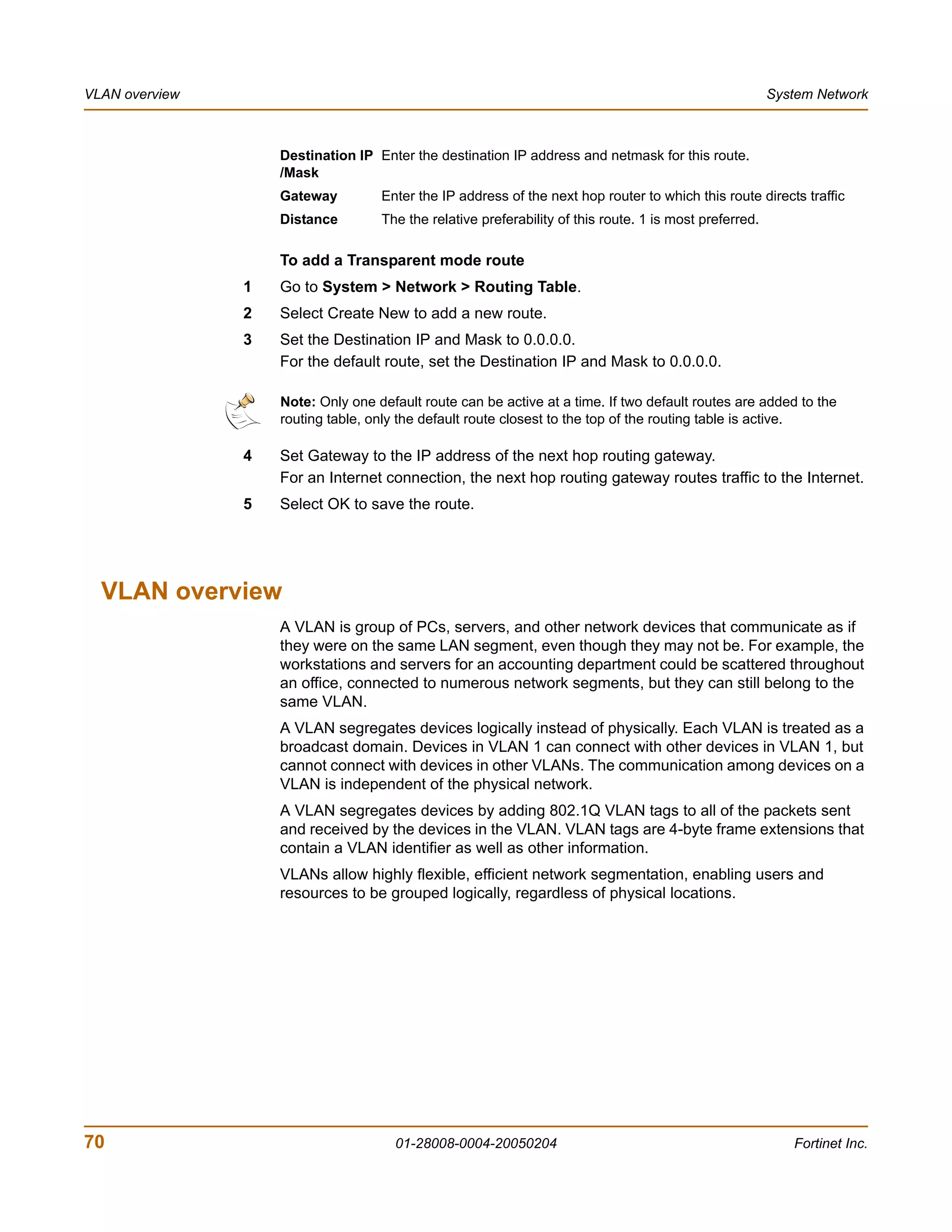
![System Status Changing the FortiGate firmware
7 Type y.
As the FortiGate units starts, a series of system startup messages is displayed.
When one of the following messages appears:
• FortiGate unit running v2.x BIOS
Press Any Key To Download Boot Image.
...
• FortiGate unit running v3.x BIOS
Press any key to display configuration menu.....
......
Immediately press any key to interrupt the system startup.
Note: You have only 3 seconds to press any key. If you do not press a key soon enough, the
FortiGate unit reboots and you must log in and repeat the execute reboot command.
If you successfully interrupt the startup process, one of the following messages
appears:
• FortiGate unit running v2.x BIOS
Enter TFTP Server Address [192.168.1.168]:
Go to step 9.
• FortiGate unit running v3.x BIOS
[G]: Get firmware image from TFTP server.
[F]: Format boot device.
[B]: Boot with backup firmware and set as default.
[Q]: Quit menu and continue to boot with default firmware.
[H]: Display this list of options.
Enter G,F,B,Q,or H:
8 Type G to get the new firmware image from the TFTP server.
The following message appears:
Enter TFTP server address [192.168.1.168]:
9 Type the address of the TFTP server and press Enter.
The following message appears:
Enter Local Address [192.168.1.188]:
10 Type an IP address that the FortiGate unit can use to connect to the TFTP server.
The IP address can be any IP address that is valid for the network that the interface is
connected to. Make sure you do not enter the IP address of another device on this
network.
The following message appears:
Enter File Name [image.out]:
FortiGate-200 Administration Guide 01-28008-0004-20050204 47](https://image.slidesharecdn.com/01-28008-0004-20050204fortigate-200administrationguide-121225111736-phpapp02/75/01-28008-0004-20050204-forti-gate-200_administration-guide-47-2048.jpg)
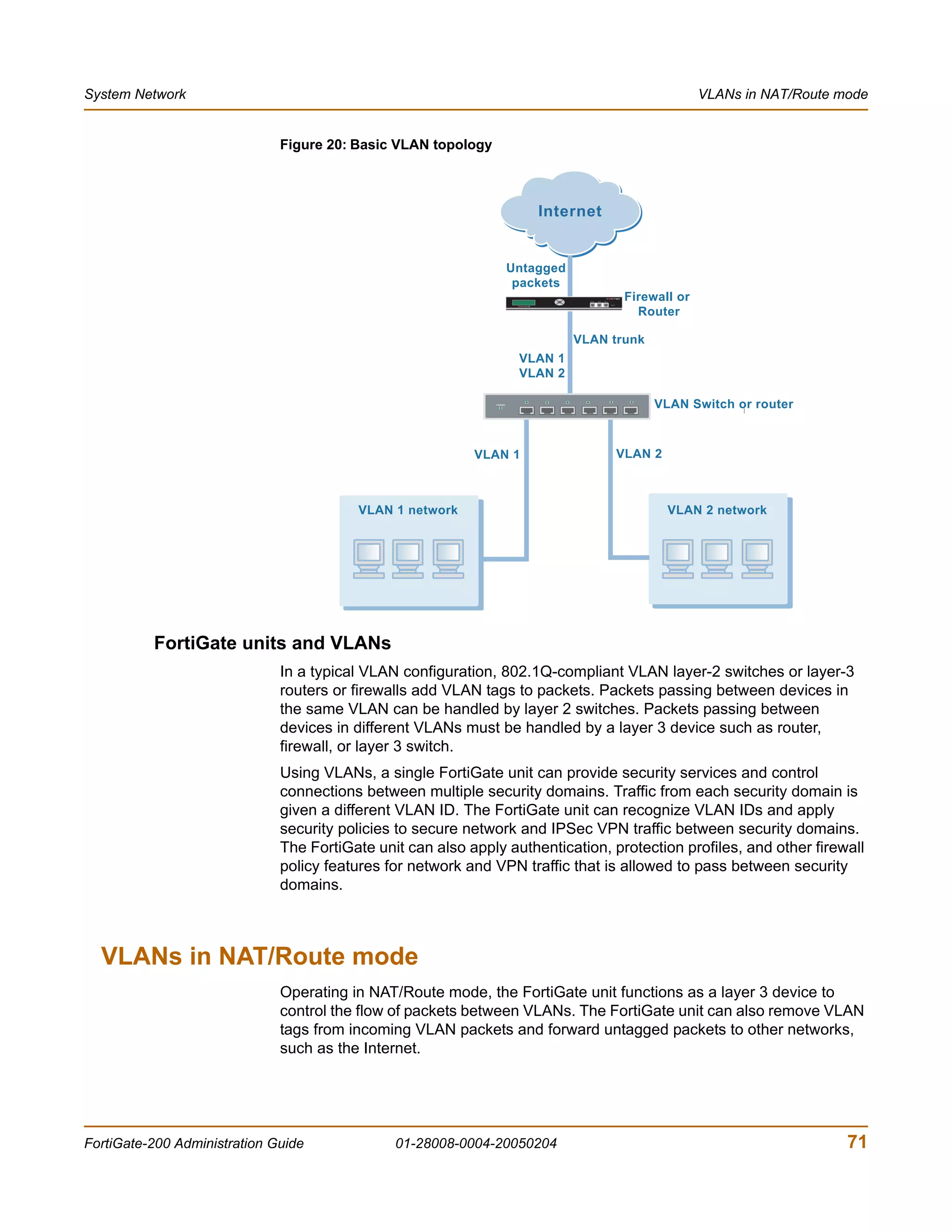
![Changing the FortiGate firmware System Status
11 Enter the firmware image filename and press Enter.
The TFTP server uploads the firmware image file to the FortiGate unit and messages
similar to the following are displayed:
• FortiGate unit running v2.x BIOS
Do You Want To Save The Image? [Y/n]
Type Y.
• FortiGate unit running v3.x BIOS
Save as Default firmware/Run image without saving:[D/R]
or
Save as Default firmware/Backup firmware/Run image without
saving:[D/B/R]
12 Type D.
The FortiGate unit installs the new firmware image and restarts. The installation might
take a few minutes to complete.
Restoring the previous configuration
Change the internal interface address if required. You can do this from the CLI using
the command:
config system interface
edit internal
set ip <address_ipv4mask>
set allowaccess {ping https ssh telnet http}
end
After changing the interface address, you can access the FortiGate unit from the
web-based manager and restore the configuration.
• To restore the FortiGate unit configuration, see “Backup and restore” on page 127.
• To restore IPS custom signatures, see “Backing up and restoring custom signature
files” on page 298.
• To restore web content filtering lists, see “Backup and restore” on page 127.
• To restore email filtering lists, see “Backup and restore” on page 127.
• To update the virus and attack definitions to the most recent version, see “Updating
antivirus and attack definitions” on page 132.
If you are reverting to a previous firmware version (for example, reverting from
FortiOS v2.80 to FortiOS v2.50), you might not be able to restore your previous
configuration from the backup up configuration file.
Testing a new firmware image before installing it
You can test a new firmware image by installing the firmware image from a system
reboot and saving it to system memory. After completing this procedure the FortiGate
unit operates using the new firmware image with the current configuration. This new
firmware image is not permanently installed. The next time the FortiGate unit restarts,
it operates with the originally installed firmware image using the current configuration.
If the new firmware image operates successfully, you can install it permanently using
the procedure “Upgrading to a new firmware version” on page 41.
48 01-28008-0004-20050204 Fortinet Inc.](https://image.slidesharecdn.com/01-28008-0004-20050204fortigate-200administrationguide-121225111736-phpapp02/75/01-28008-0004-20050204-forti-gate-200_administration-guide-48-2048.jpg)
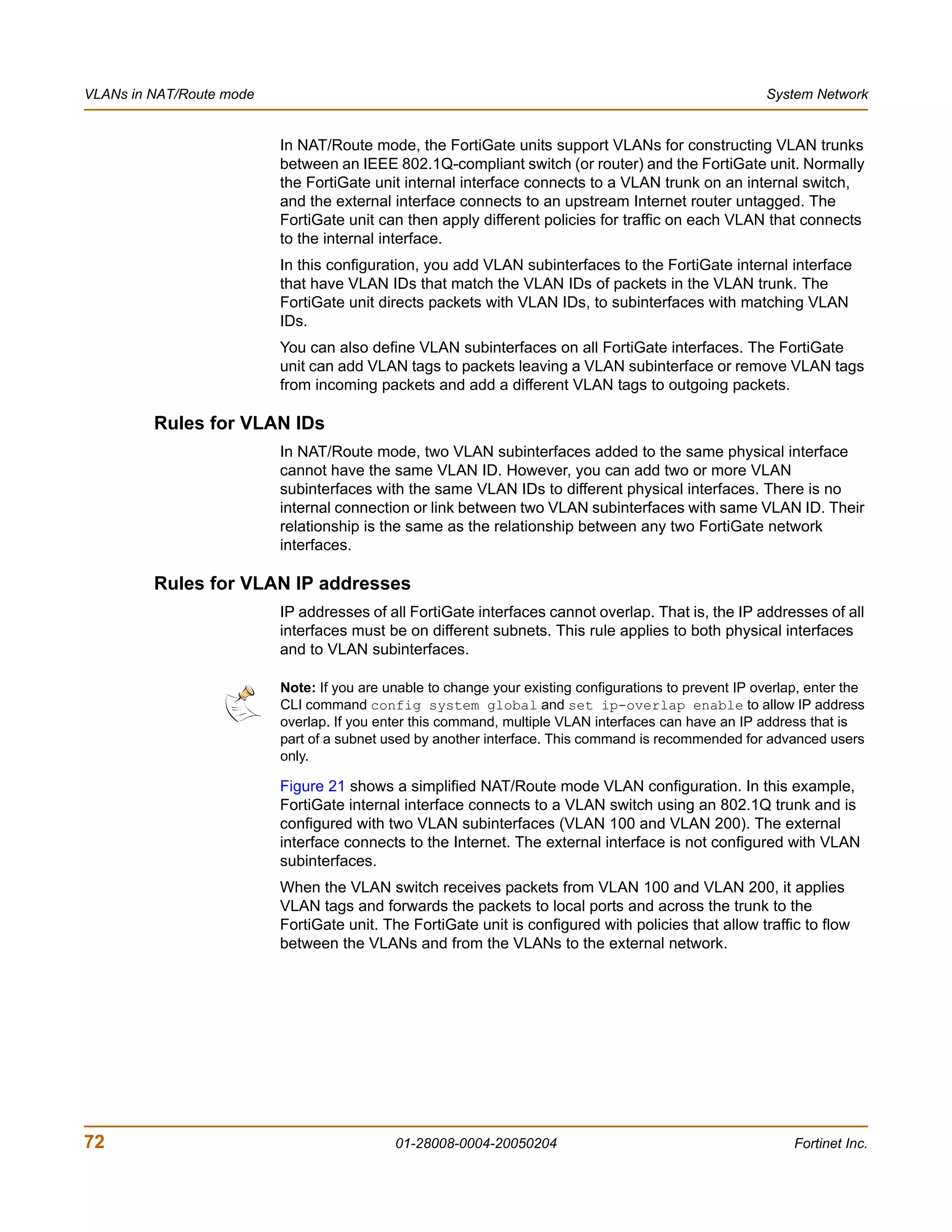
![System Status Changing the FortiGate firmware
For this procedure you:
• access the CLI by connecting to the FortiGate console port using a null-modem
cable,
• install a TFTP server that you can connect to from the FortiGate internal interface.
The TFTP server should be on the same subnet as the internal interface.
To test a new firmware image
1 Connect to the CLI using a null-modem cable and FortiGate console port.
2 Make sure the TFTP server is running.
3 Copy the new firmware image file to the root directory of the TFTP server.
4 Make sure that the internal interface is connected to the same network as the TFTP
server.
You can use the following command to ping the computer running the TFTP server.
For example, if the TFTP server's IP address is 192.168.1.168:
execute ping 192.168.1.168
5 Enter the following command to restart the FortiGate unit:
execute reboot
6 As the FortiGate unit reboots, press any key to interrupt the system startup.
As the FortiGate units starts, a series of system startup messages are displayed.
When one of the following messages appears:
• FortiGate unit running v2.x BIOS
Press Any Key To Download Boot Image.
...
• FortiGate unit running v3.x BIOS
Press any key to display configuration menu.....
......
7 Immediately press any key to interrupt the system startup.
Note: You have only 3 seconds to press any key. If you do not press a key soon enough, the
FortiGate unit reboots and you must log in and repeat the execute reboot command.
If you successfully interrupt the startup process, one of the following messages
appears:
• FortiGate unit running v2.x BIOS
Enter TFTP Server Address [192.168.1.168]:
Go to step 9.
• FortiGate unit running v3.x BIOS
[G]: Get firmware image from TFTP server.
[F]: Format boot device.
[Q]: Quit menu and continue to boot with default firmware.
[H]: Display this list of options.
Enter G,F,Q,or H:
FortiGate-200 Administration Guide 01-28008-0004-20050204 49](https://image.slidesharecdn.com/01-28008-0004-20050204fortigate-200administrationguide-121225111736-phpapp02/75/01-28008-0004-20050204-forti-gate-200_administration-guide-49-2048.jpg)
![Changing the FortiGate firmware System Status
8 Type G to get the new firmware image from the TFTP server.
The following message appears:
Enter TFTP server address [192.168.1.168]:
9 Type the address of the TFTP server and press Enter.
The following message appears:
Enter Local Address [192.168.1.188]:
10 Type an IP address that can be used by the FortiGate unit to connect to the FTP
server.
The IP address must be on the same network as the TFTP server, but make sure you
do not use the IP address of another device on this network.
The following message appears:
Enter File Name [image.out]:
11 Enter the firmware image file name and press Enter.
The TFTP server uploads the firmware image file to the FortiGate unit and messages
similar to the following appear.
• FortiGate unit running v2.x BIOS
Do You Want To Save The Image? [Y/n]
Type N.
• FortiGate unit running v3.x BIOS
Save as Default firmware/Run image without saving:[D/R]
or
Save as Default firmware/Backup firmware/Run image without
saving:[D/B/R]
12 Type R.
The FortiGate image is installed to system memory and the FortiGate unit starts
running the new firmware image but with its current configuration.
13 You can log into the CLI or the web-based manager using any administrative account.
14 To confirm that the new firmware image has been loaded, from the CLI enter:
get system status
You can test the new firmware image as required.
Installing and using a backup firmware image
If the FortiGate unit is running BIOS version v3.x, you can install a backup firmware
image. Once the backup firmware image is installed you can switch to this backup
image when required.
• Installing a backup firmware image
• Switching to the backup firmware image
• Switching back to the default firmware image
50 01-28008-0004-20050204 Fortinet Inc.](https://image.slidesharecdn.com/01-28008-0004-20050204fortigate-200administrationguide-121225111736-phpapp02/75/01-28008-0004-20050204-forti-gate-200_administration-guide-50-2048.jpg)
![System Status Changing the FortiGate firmware
Installing a backup firmware image
To run this procedure you:
• access the CLI by connecting to the FortiGate console port using a null-modem
cable,
• install a TFTP server that you can connect to from the FortiGate as described in
the procedure “Installing firmware images from a system reboot using the CLI” on
page 45.
To install a backup firmware image
1 Connect to the CLI using the null-modem cable and FortiGate console port.
2 Make sure that the TFTP server is running.
3 Copy the new firmware image file to the root directory of your TFTP server.
4 To confirm that the FortiGate unit can connect to the TFTP server, use the following
command to ping the computer running the TFTP server. For example, if the IP
address of the TFTP server is 192.168.1.168:
execute ping 192.168.1.168
5 Enter the following command to restart the FortiGate unit:
execute reboot
As the FortiGate unit starts, a series of system startup messages are displayed.
When of the following message appears:
Press any key to enter configuration menu.....
......
6 Immediately press any key to interrupt the system startup.
Note: You have only 3 seconds to press any key. If you do not press a key soon enough, the
FortiGate unit reboots and you must log in and repeat the execute reboot command.
If you successfully interrupt the startup process, the following message appears:
[G]: Get firmware image from TFTP server.
[F]: Format boot device.
[B]: Boot with backup firmware and set as default.
[Q]: Quit menu and continue to boot with default firmware.
[H]: Display this list of options.
Enter G,F,B,Q,or H:
7 Type G to get the new firmware image from the TFTP server.
The following message appears:
Enter TFTP server address [192.168.1.168]:
8 Type the address of the TFTP server and press Enter.
The following message appears:
Enter Local Address [192.168.1.188]:
FortiGate-200 Administration Guide 01-28008-0004-20050204 51](https://image.slidesharecdn.com/01-28008-0004-20050204fortigate-200administrationguide-121225111736-phpapp02/75/01-28008-0004-20050204-forti-gate-200_administration-guide-51-2048.jpg)
![Changing the FortiGate firmware System Status
9 Type an IP address that can be used by the FortiGate unit to connect to the FTP
server.
The IP address can be any IP address that is valid for the network that the interface is
connected to. Make sure you do not enter the IP address of another device on this
network.
The following message appears:
Enter File Name [image.out]:
10 Enter the firmware image file name and press Enter.
The TFTP server uploads the firmware image file to the FortiGate unit and the
following message is displayed.
Save as Default firmware/Backup firmware/Run image without
saving:[D/B/R]
11 Type B.
The FortiGate unit saves the backup firmware image and restarts. When the FortiGate
unit restarts it is running the previously installed firmware version.
Switching to the backup firmware image
Use this procedure to switch the FortiGate unit to operating with a backup firmware
image that you previously installed. When you switch the FortiGate unit to the backup
firmware image, the FortiGate unit operates using the configuration that was saved
with that firmware image.
If you install a new backup image from a reboot, the configuration saved with this
firmware image is the factory default configuration. If you use the procedure
“Switching back to the default firmware image” on page 53 to switch to a backup
firmware image that was previously running as the default firmware image, the
configuration saved with this firmware image is restored.
To switch to the backup firmware image
1 Connect to the CLI using the null-modem cable and FortiGate console port.
2 Enter the following command to restart the FortiGate unit:
execute reboot
As the FortiGate units starts, a series of system startup messages are displayed.
When the following message appears:
Press any key to enter configuration menu.....
......
3 Immediately press any key to interrupt the system startup.
Note: You have only 3 seconds to press any key. If you do not press a key soon enough, the
FortiGate unit reboots and you must log in and repeat the execute reboot command.
52 01-28008-0004-20050204 Fortinet Inc.](https://image.slidesharecdn.com/01-28008-0004-20050204fortigate-200administrationguide-121225111736-phpapp02/75/01-28008-0004-20050204-forti-gate-200_administration-guide-52-2048.jpg)
![System Status Changing the FortiGate firmware
If you successfully interrupt the startup process, the following message appears:
[G]: Get firmware image from TFTP server.
[F]: Format boot device.
[B]: Boot with backup firmware and set as default.
[Q]: Quit menu and continue to boot with default firmware.
[H]: Display this list of options.
Enter G,F,B,Q,or H:
4 Type B to load the backup firmware image.
The FortiGate unit loads the backup firmware image and restarts. When the FortiGate
unit restarts, it is running the backup firmware version and the configuration is set to
factory default.
Switching back to the default firmware image
Use this procedure to switch the FortiGate unit to operating with the backup firmware
image that had been running as the default firmware image. When you switch to this
backup firmware image, the configuration saved with this firmware image is restored.
To switch back to the default firmware image
1 Connect to the CLI using the null-modem cable and FortiGate console port.
2 Enter the following command to restart the FortiGate unit:
execute reboot
As the FortiGate units starts, a series of system startup messages are displayed.
When the following message appears:
Press any key to enter configuration menu.....
......
3 Immediately press any key to interrupt the system startup.
Note: You have only 3 seconds to press any key. If you do not press a key soon enough, the
FortiGate unit reboots and you must log in and repeat the execute reboot command.
If you successfully interrupt the startup process, the following message appears:
[G]: Get firmware image from TFTP server.
[F]: Format boot device.
[B]: Boot with backup firmware and set as default.
[Q]: Quit menu and continue to boot with default firmware.
[H]: Display this list of options.
Enter G,F,B,Q,or H:
4 Type B to load the backup firmware image.
The FortiGate unit loads the backup firmware image and restarts. When the FortiGate
unit restarts it is running the backup firmware version with a restored configuration.
FortiGate-200 Administration Guide 01-28008-0004-20050204 53](https://image.slidesharecdn.com/01-28008-0004-20050204fortigate-200administrationguide-121225111736-phpapp02/75/01-28008-0004-20050204-forti-gate-200_administration-guide-53-2048.jpg)


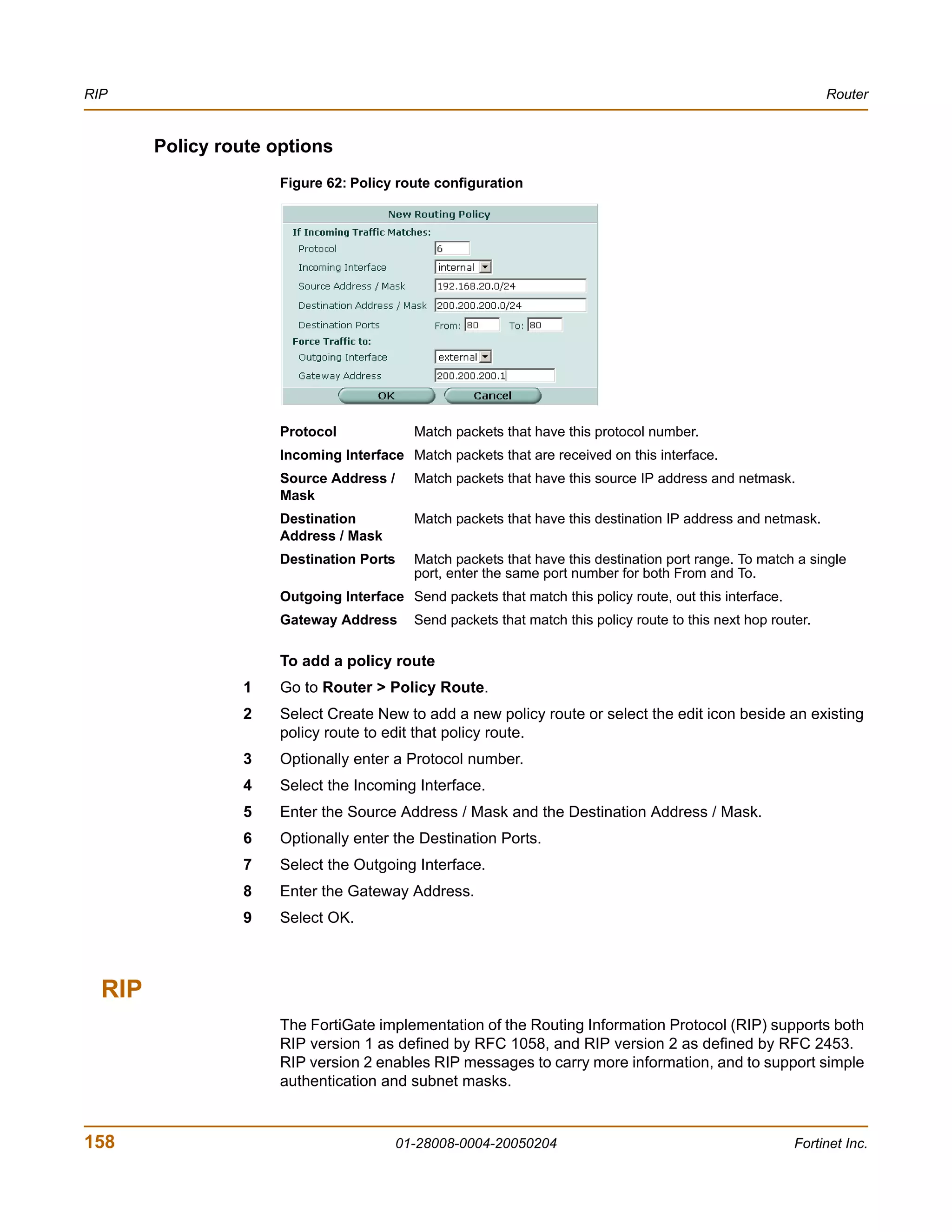
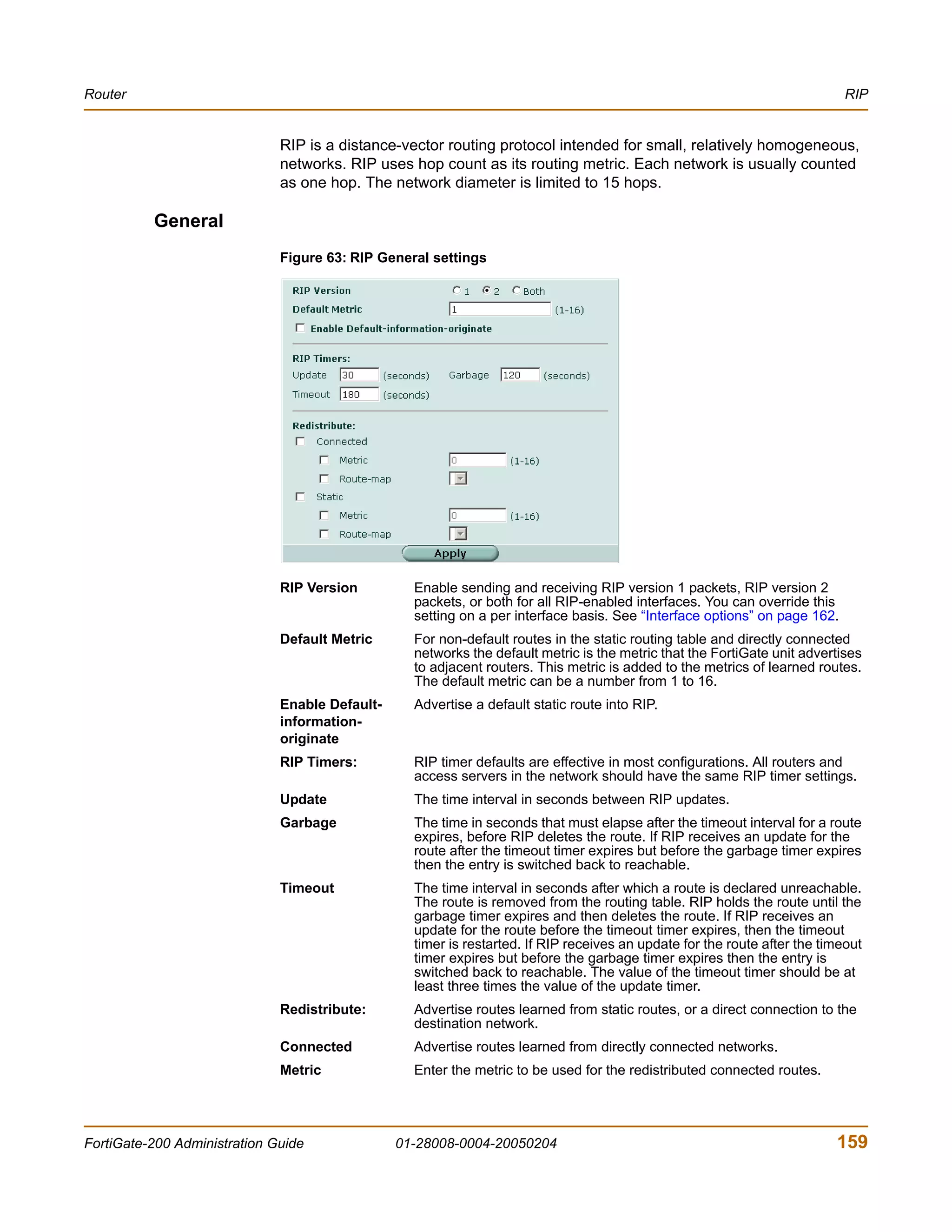

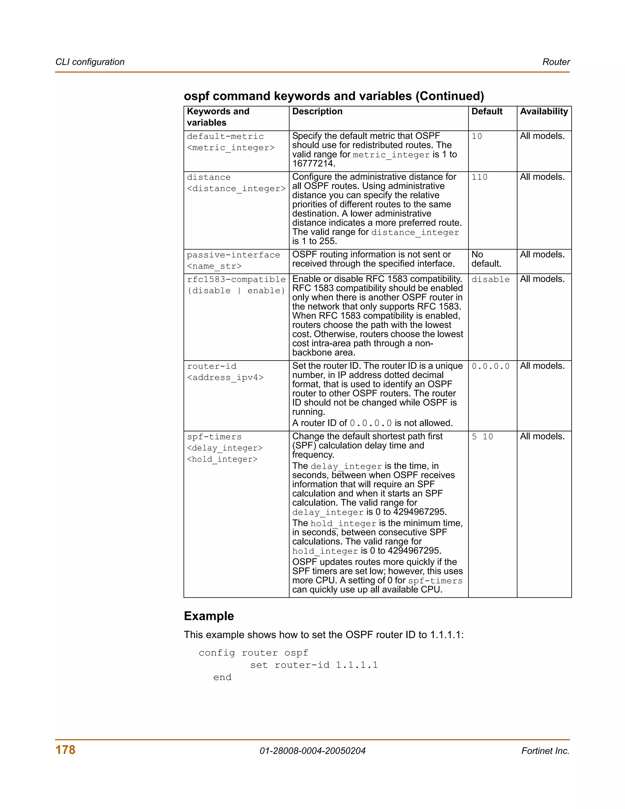
![Router CLI configuration
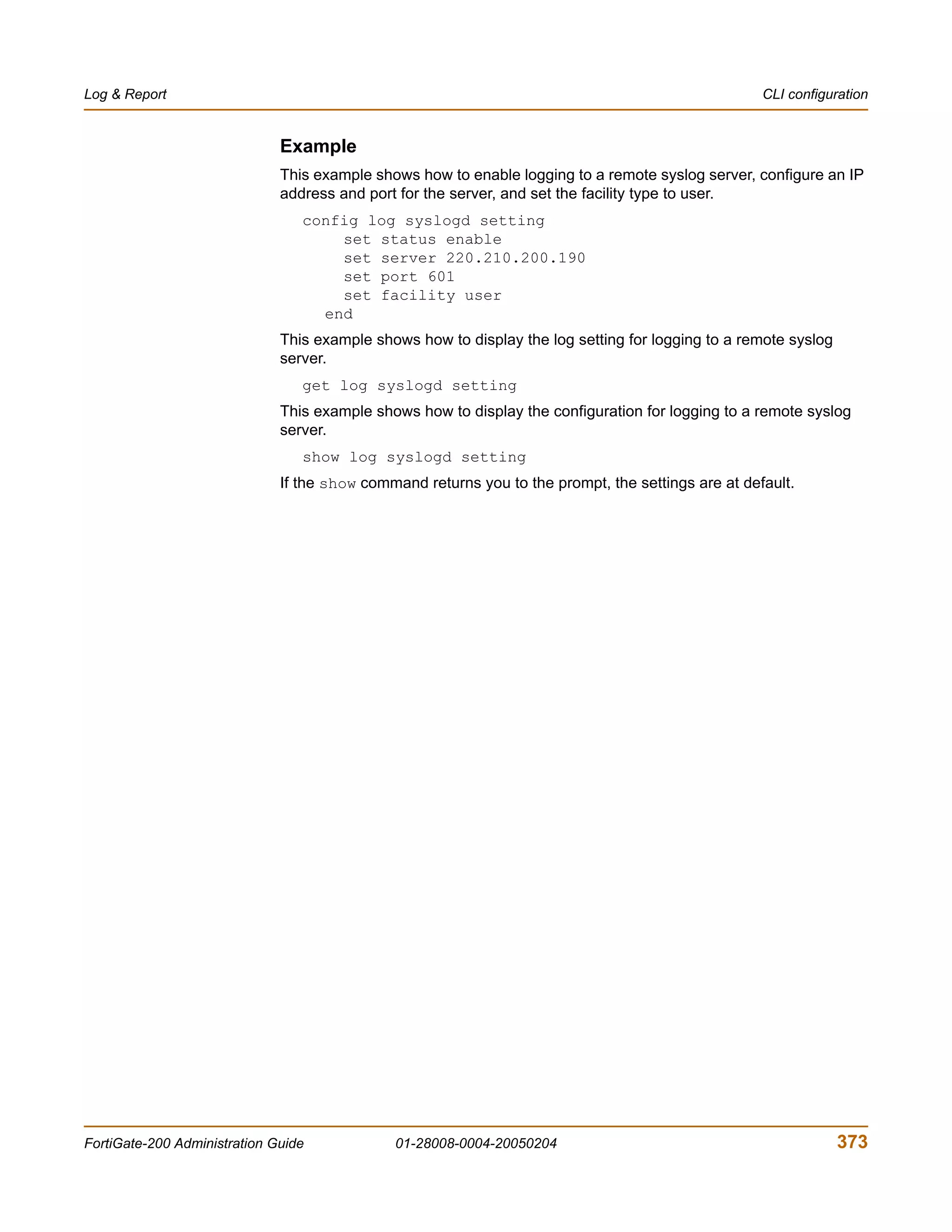
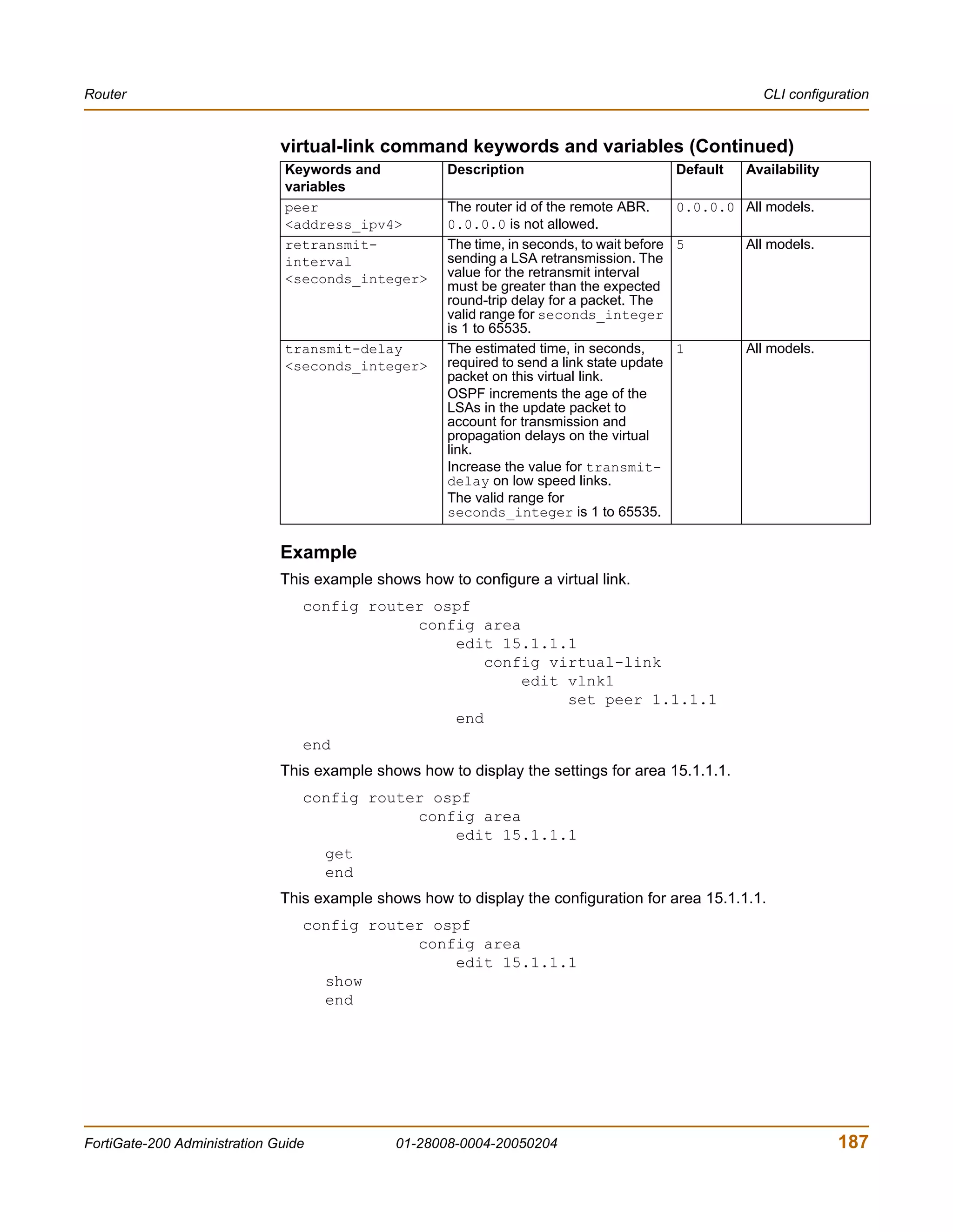
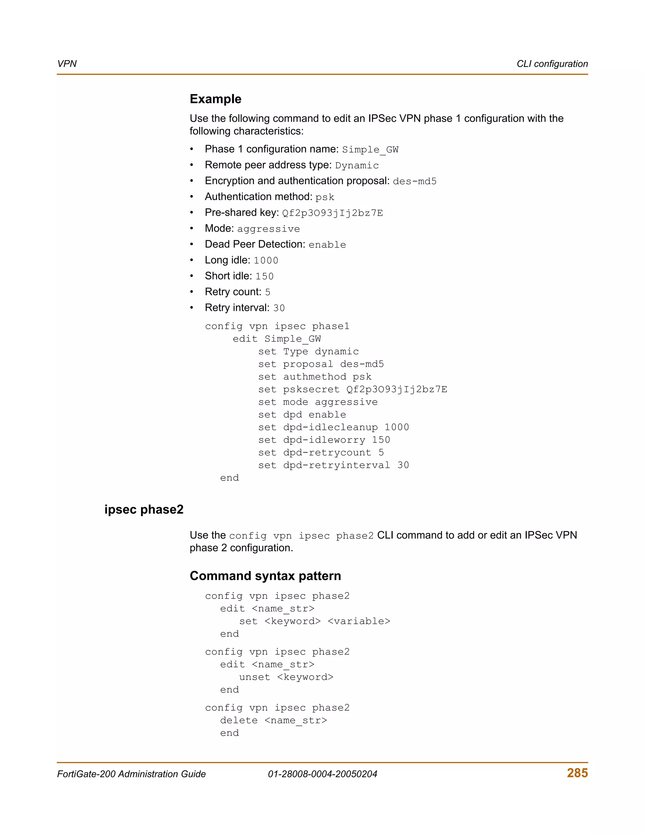
Example
This example shows how to summarize routes using the prefix 10.0.0.0 255.0.0.0.
config router ospf
config summary-address
edit 5
set prefix 10.0.0.0 255.0.0.0
end
end
This example shows how to display the OSPF settings.
get router ospf
This example shows how to display the OSPF configuration.
show router ospf
config router static6
Use this command to add, edit, or delete static routes for IPv6 traffic. Add static routes
to control the destination of traffic exiting the FortiGate unit. You configure routes by
adding destination IP addresses and netmasks and adding gateways for these
destination addresses. The gateways are the next hop routers to which to route traffic
that matches the destination addresses in the route.
The FortiGate unit assigns routes using a best match algorithm. To select a route for a
packet, the FortiGate unit searches through the routing table for a route that best
matches the destination address of the packet. If a match is not found, the FortiGate
unit routes the packet using the default route.
Command syntax pattern
config router static6
edit <sequence_integer>
set <keyword> <variable>
end
config router static6
edit <sequence_integer>
unset <keyword>
end
config router static6
delete <sequence_integer>
end
get router static6 [<sequence_integer>]
show router static6 [<sequence_integer>]
FortiGate-200 Administration Guide 01-28008-0004-20050204 199](https://image.slidesharecdn.com/01-28008-0004-20050204fortigate-200administrationguide-121225111736-phpapp02/75/01-28008-0004-20050204-forti-gate-200_administration-guide-199-2048.jpg)
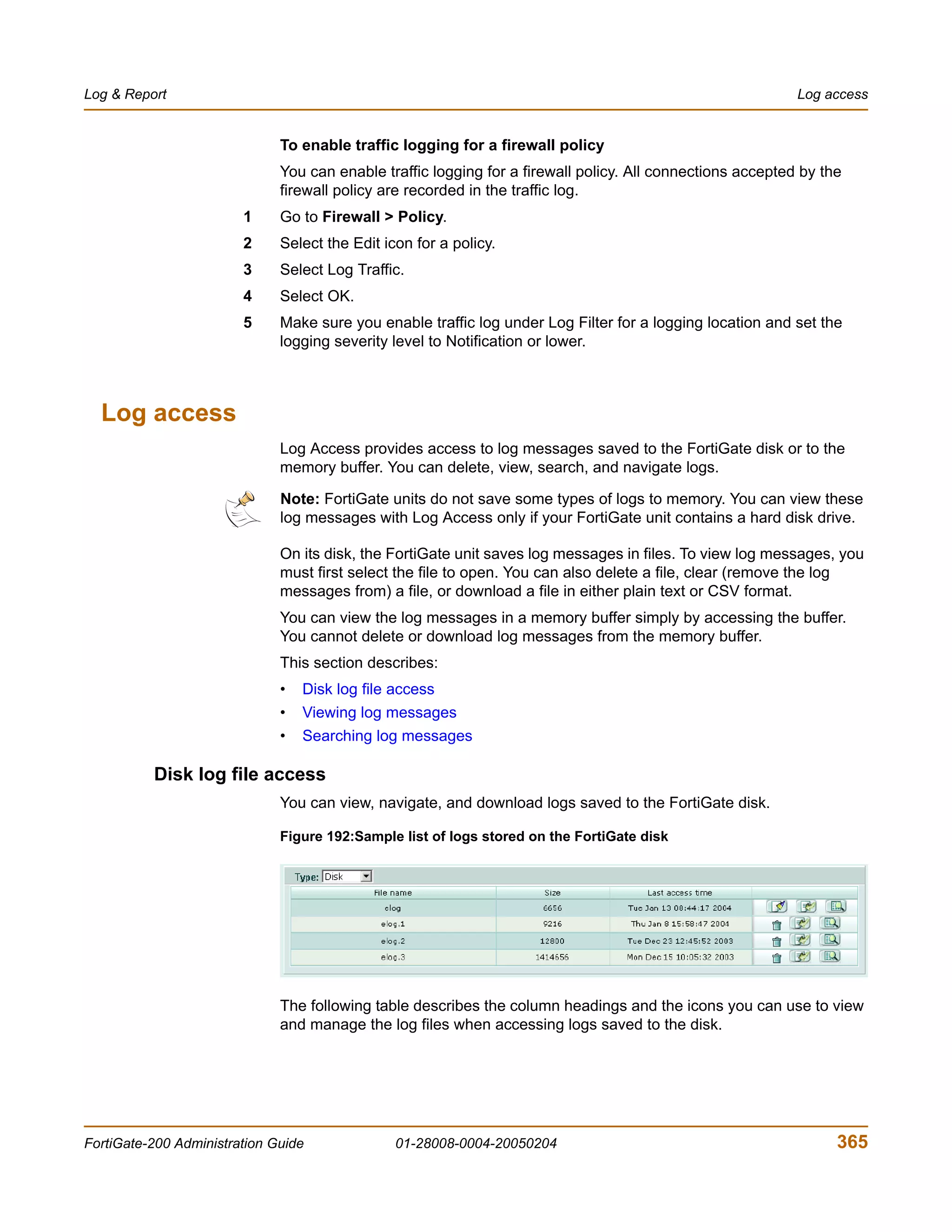
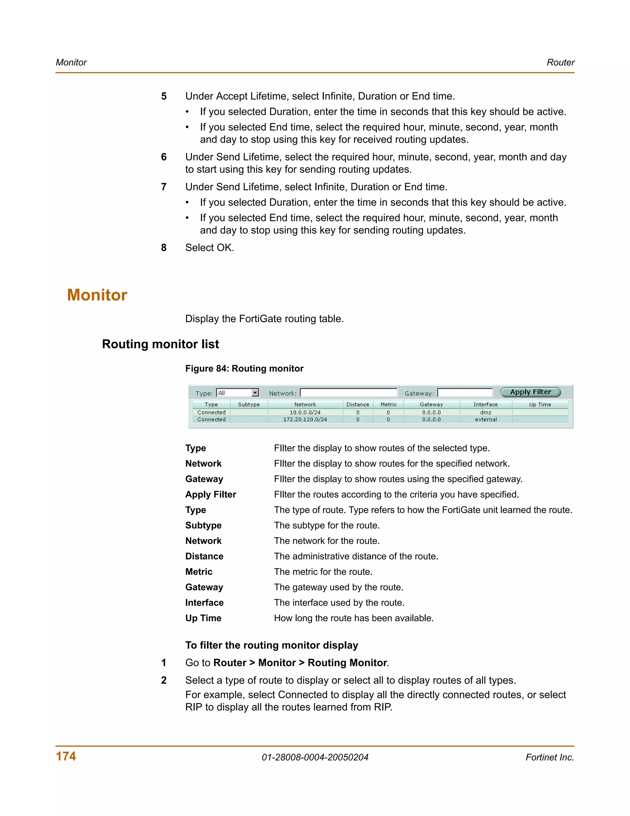
![Firewall Address
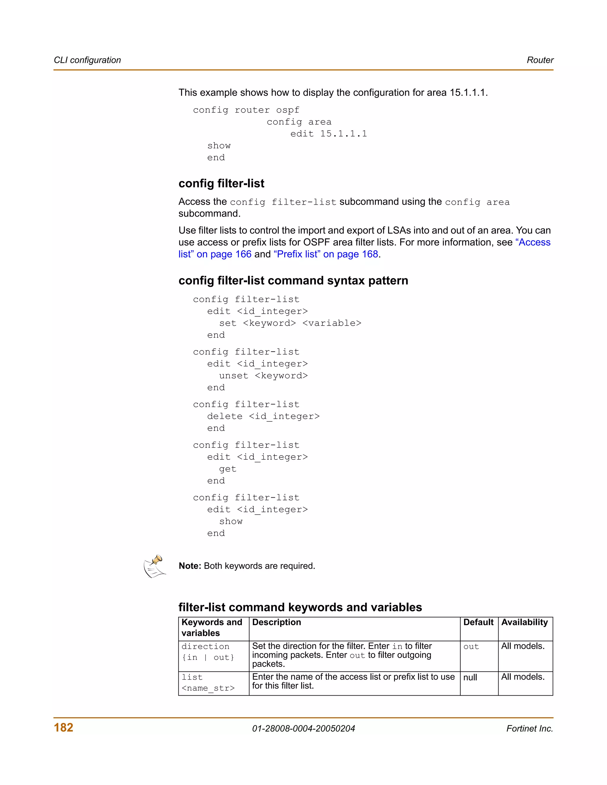
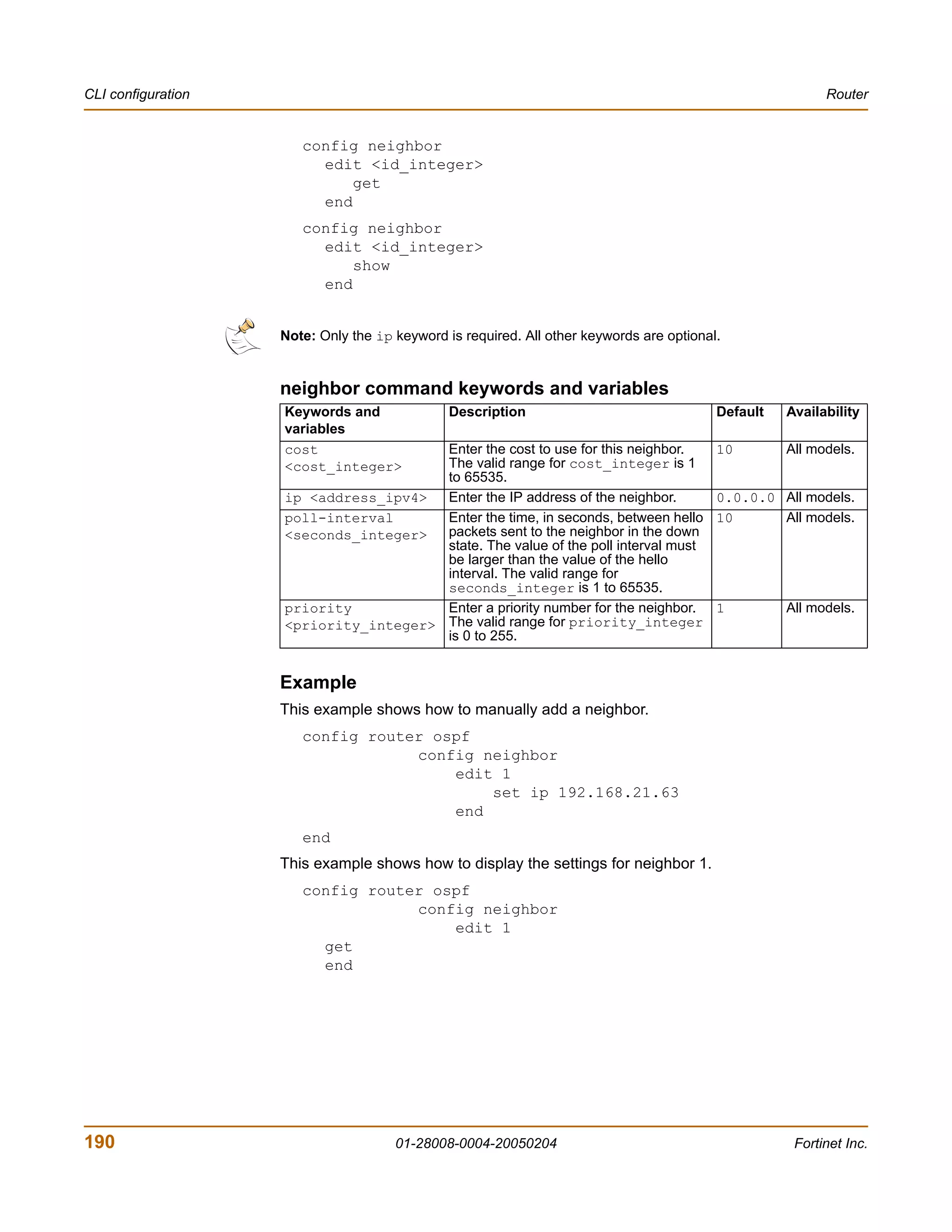
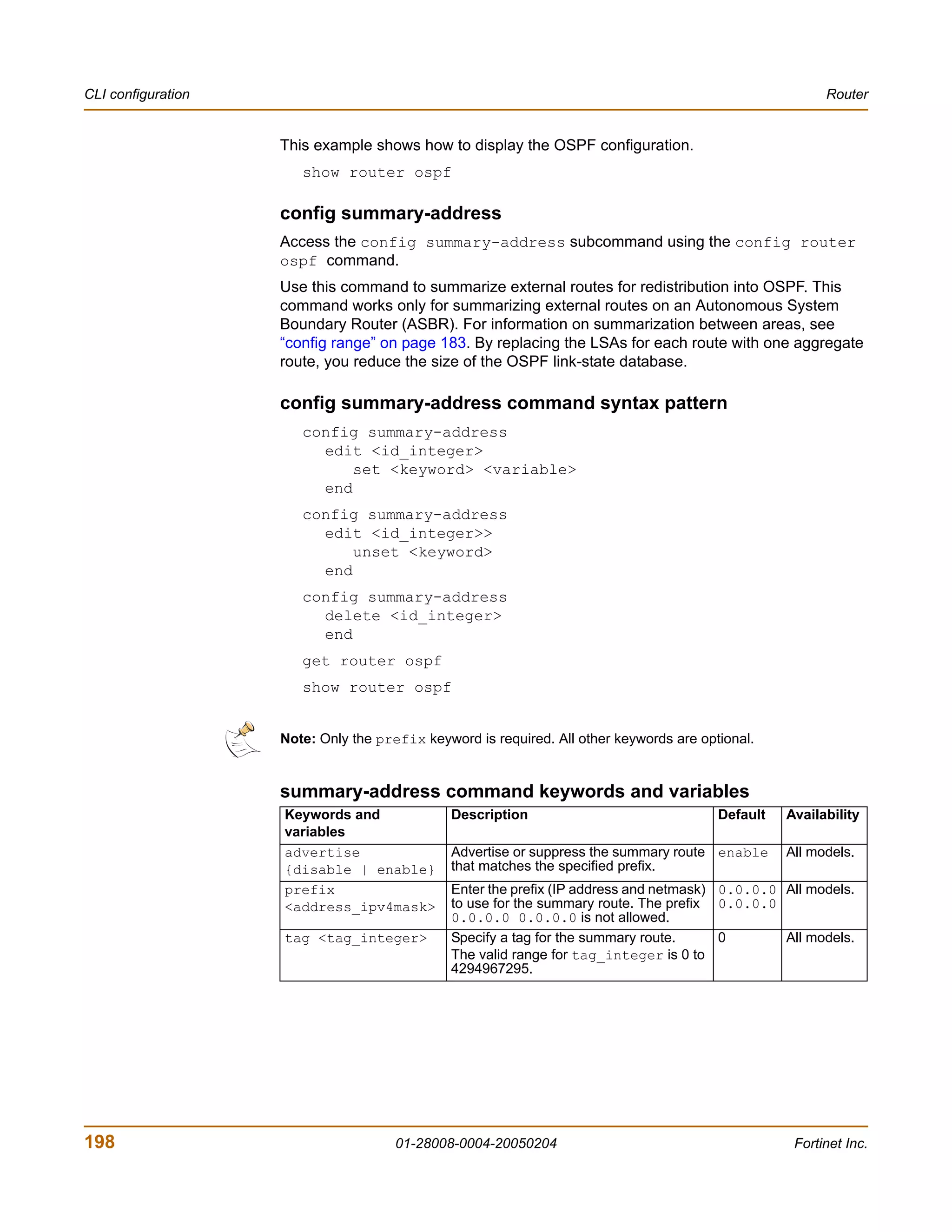
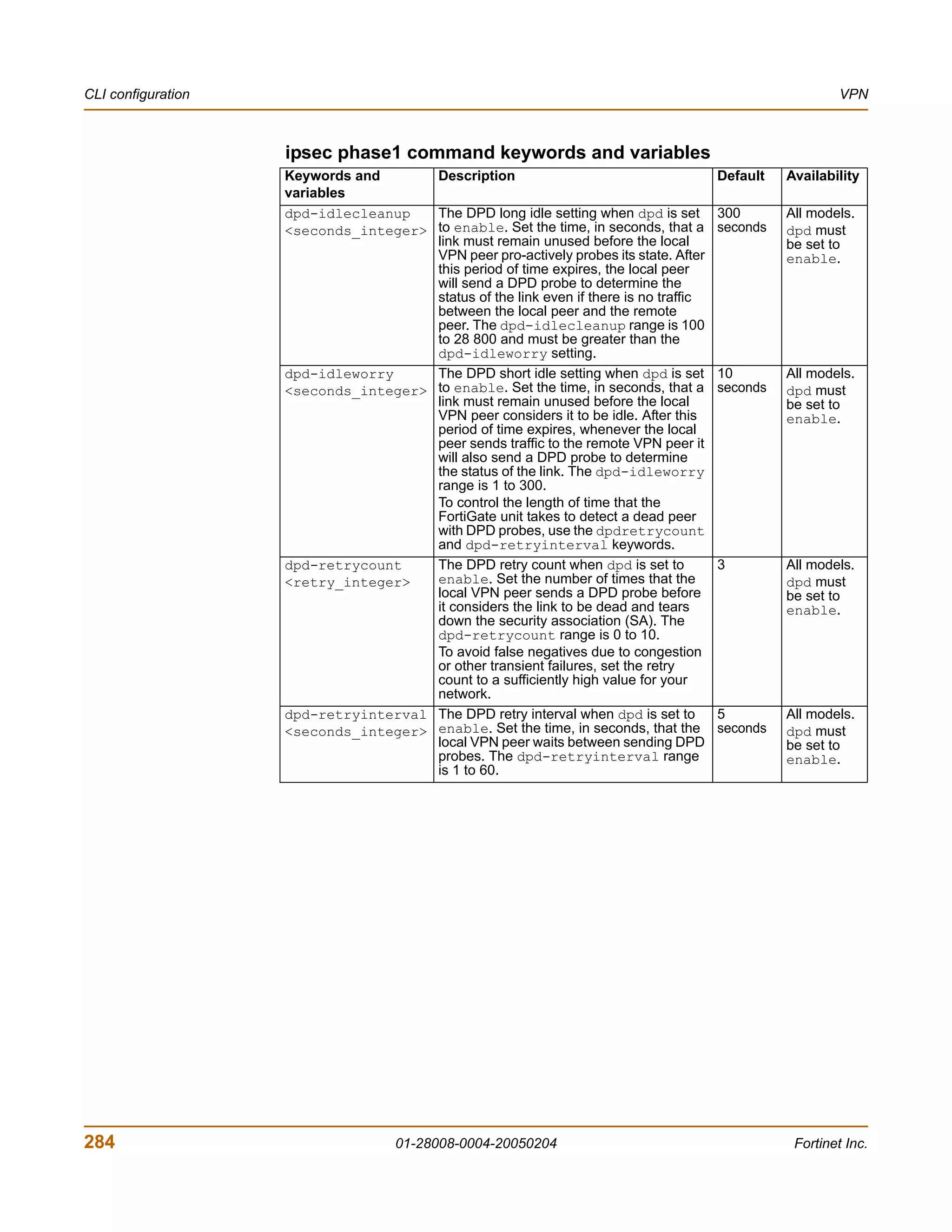
firewall policy command keywords and variables
Keywords and variables Description Default Availability
http_retry_count Define the number of times to retry 0 All models.
<retry_integer> establishing an HTTP connection when
the connection fails.
natip Configure natip for a firewall policy 0.0.0.0 All models.
<address_ipv4mask> with action set to encrypt and with 0.0.0.0 Encrypt
outbound NAT enabled. Specify the IP policy, with
address and subnet mask to translate outbound
the source address of outgoing NAT
packets. enabled.
Set natip for peer to peer VPNs to
control outbound NAT IP address
translation for outgoing VPN packets.
If you do not use natip to translate IP
addresses, the source addresses of
outbound VPN packets are translated
into the IP address of the FortiGate
external interface. If you use natip, the
FortiGate unit uses a static mapping
scheme to translate the source
addresses of VPN packets into
corresponding IP addresses on the
subnet that you specify. For example, if
the source address in the encryption
policy is 192.168.1.0/24 and the natip is
172.16.2.0/24, a source address of
192.168.1.7 will be translated to
172.16.2.7
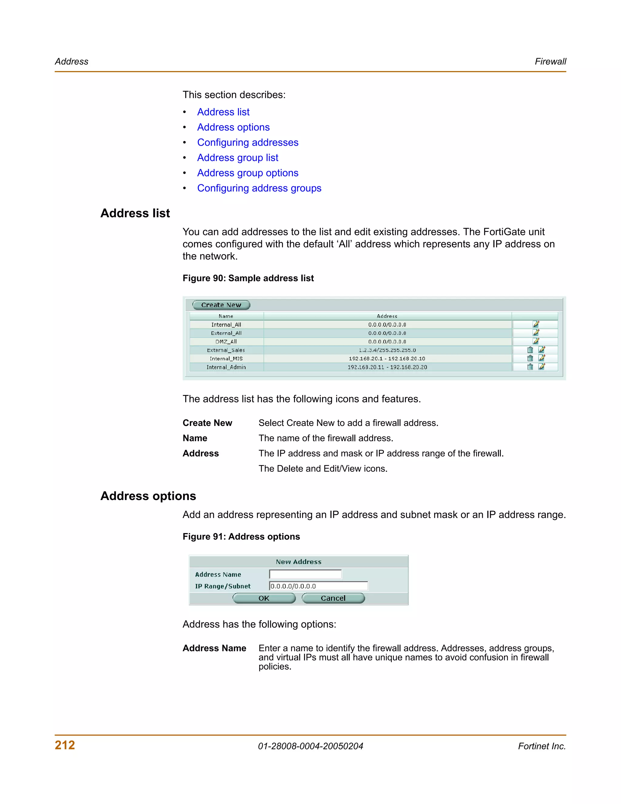
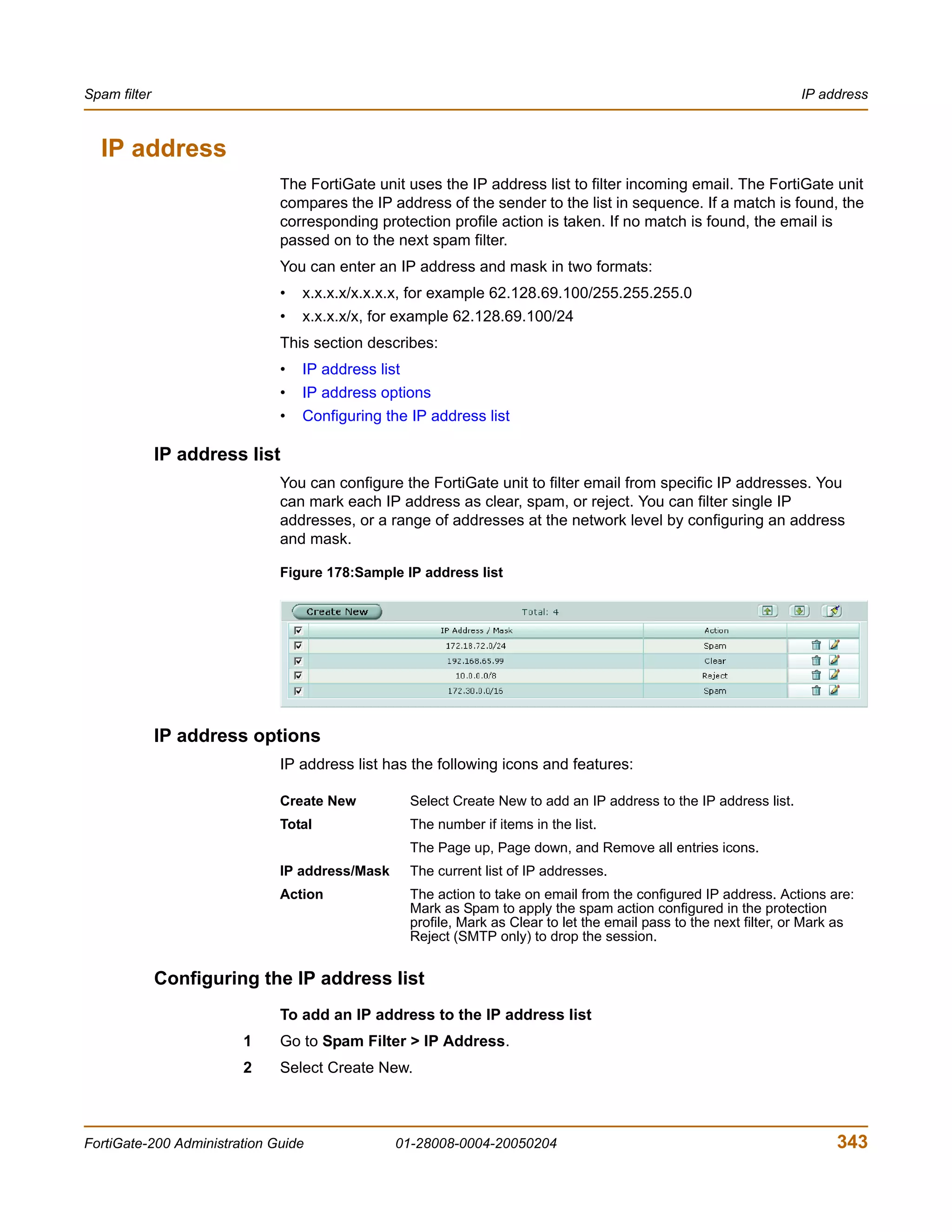
Address
You can add, edit, and delete firewall addresses as required. You can also organize
related addresses into address groups to simplify policy creation.
A firewall address can be configured with a name, an IP address, and a netmask, or a
name and IP address range.
You can enter an IP address and netmask using the following formats.
• x.x.x.x/x.x.x.x, for example 64.198.45.0/255.255.255.0
• x.x.x.x/x, for example 64.195.45.0/24
You can enter an IP address range using the following formats.
• x.x.x.x-x.x.x.x, for example 192.168.110.100-192.168.110.120
• x.x.x.[x-x], for example 192.168.110.[100-120]
• x.x.x.*, for example 192.168.110.* to represent all addresses on the subnet
FortiGate-200 Administration Guide 01-28008-0004-20050204 211](https://image.slidesharecdn.com/01-28008-0004-20050204fortigate-200administrationguide-121225111736-phpapp02/75/01-28008-0004-20050204-forti-gate-200_administration-guide-211-2048.jpg)
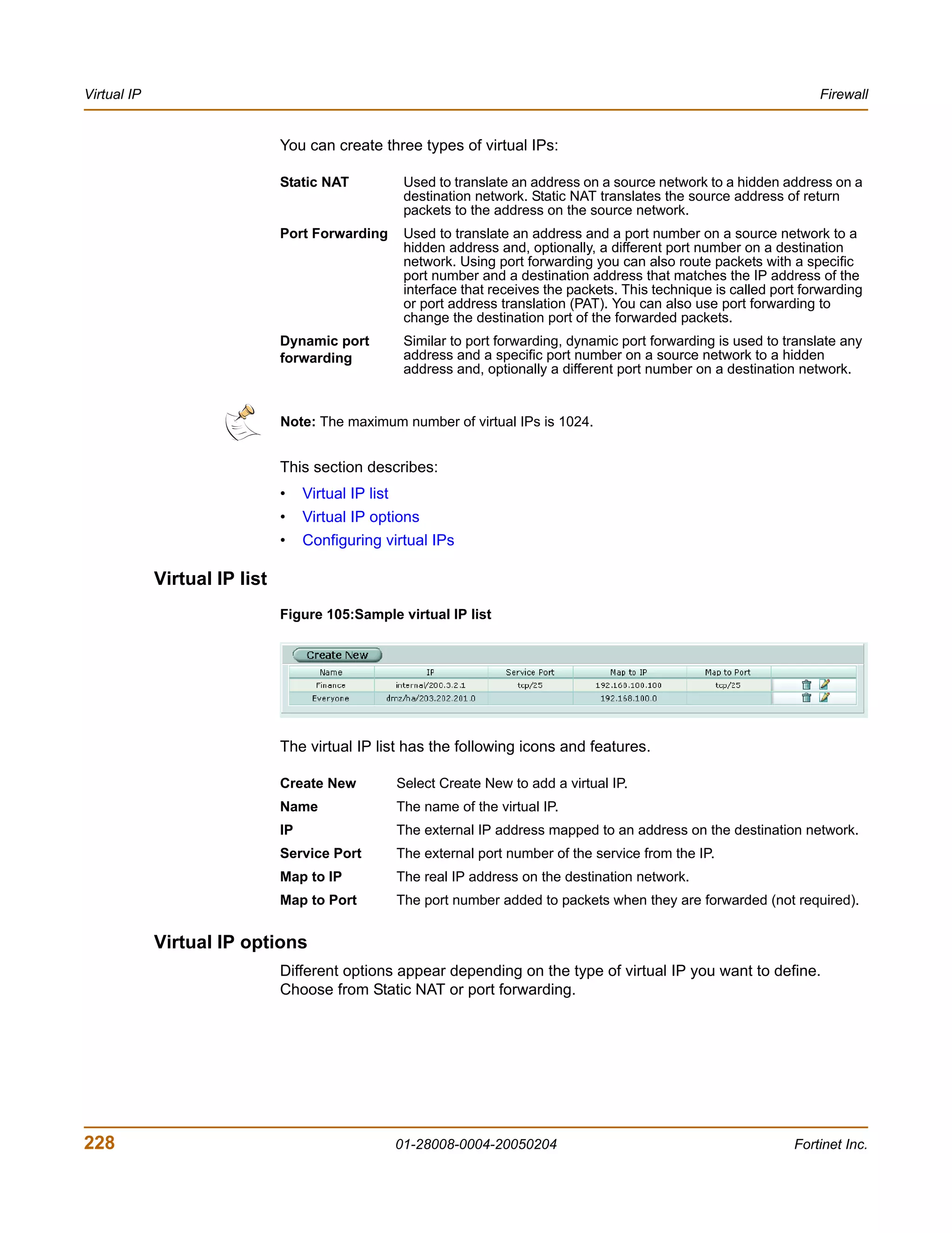
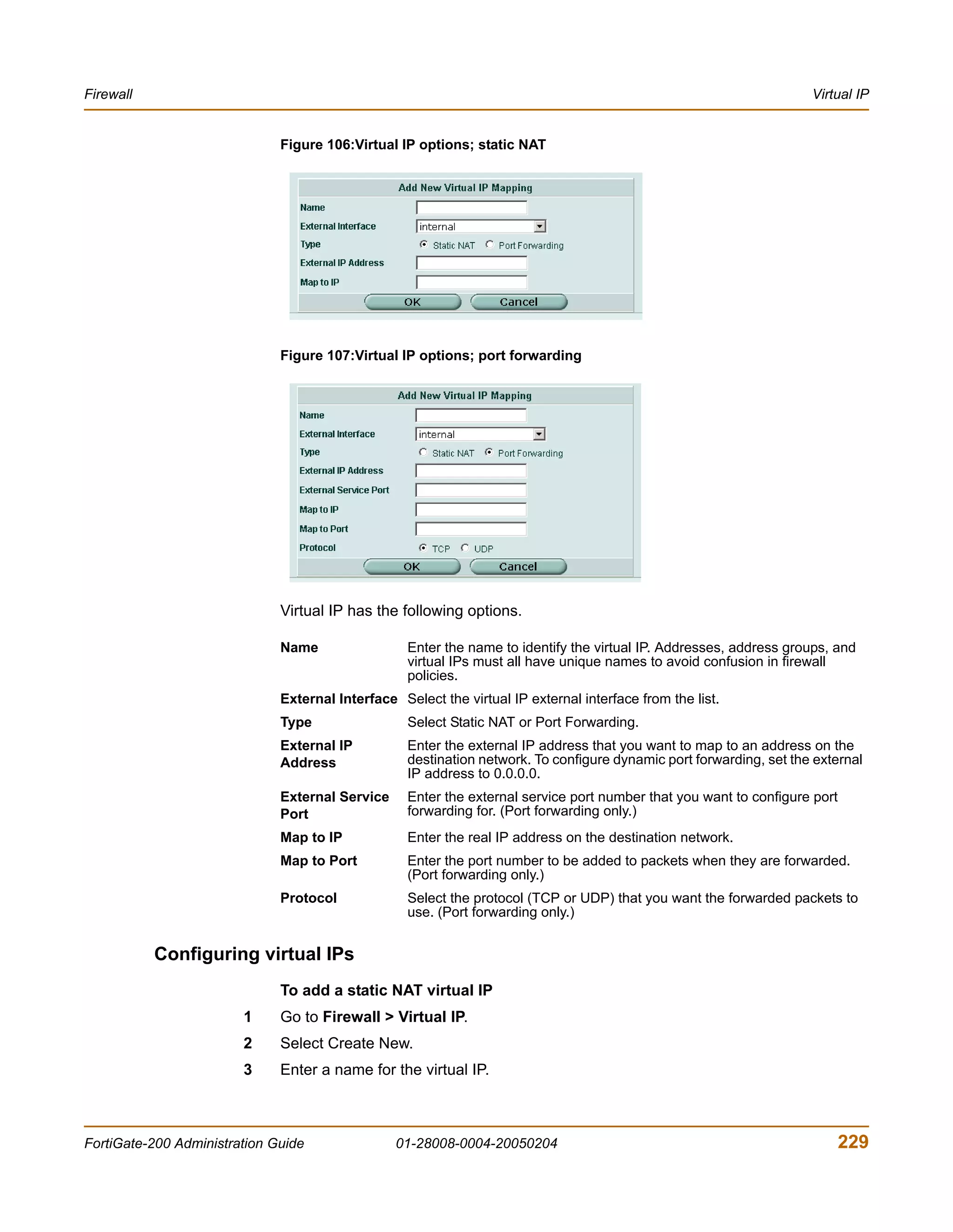
![IP pool Firewall
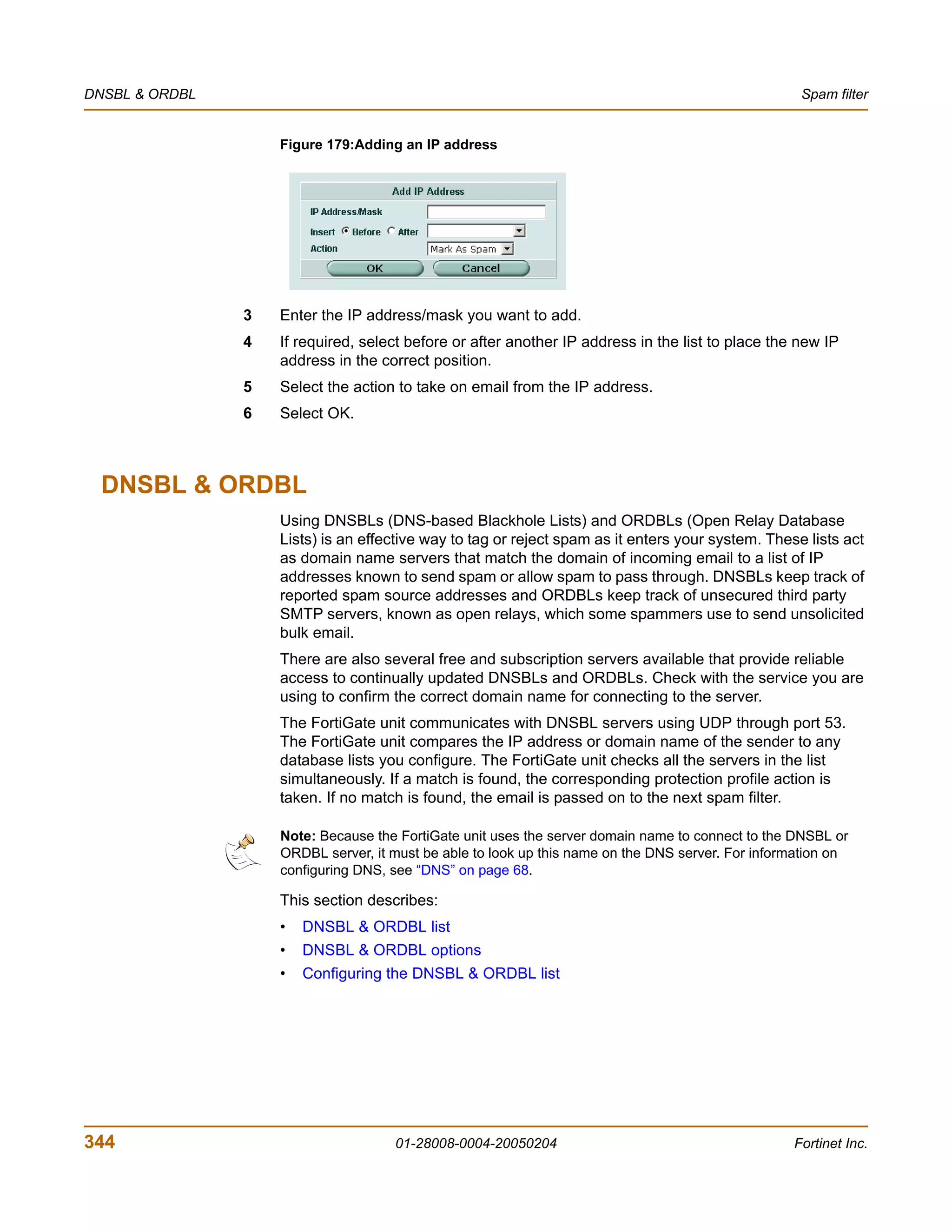
8 Enter the Map to IP address to which to map the external IP address. For example,
the IP address of a PPTP server on an internal network.
9 Enter the Map to Port number to be added to packets when they are forwarded.
If you do not want to translate the port, enter the same number as the External Service
Port.
10 Select OK.
To delete a virtual IP
1 Go to Firewall > Virtual IP.
2 Select the Delete icon beside the virtual IP you want to delete.
3 Select OK.
To edit a virtual IP
1 Go to Firewall > Virtual IP.
2 Select the Edit icon beside the virtual IP you want to modify.
3 Select OK.
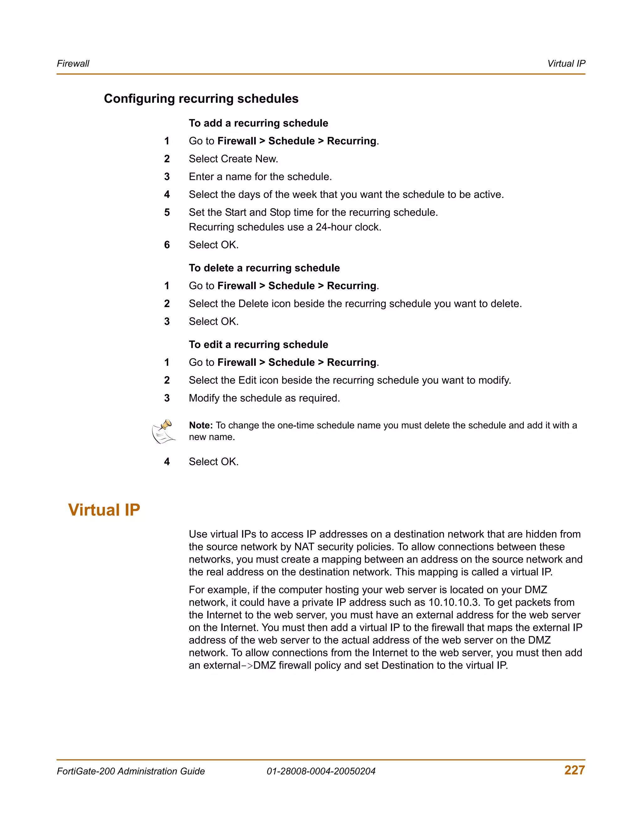
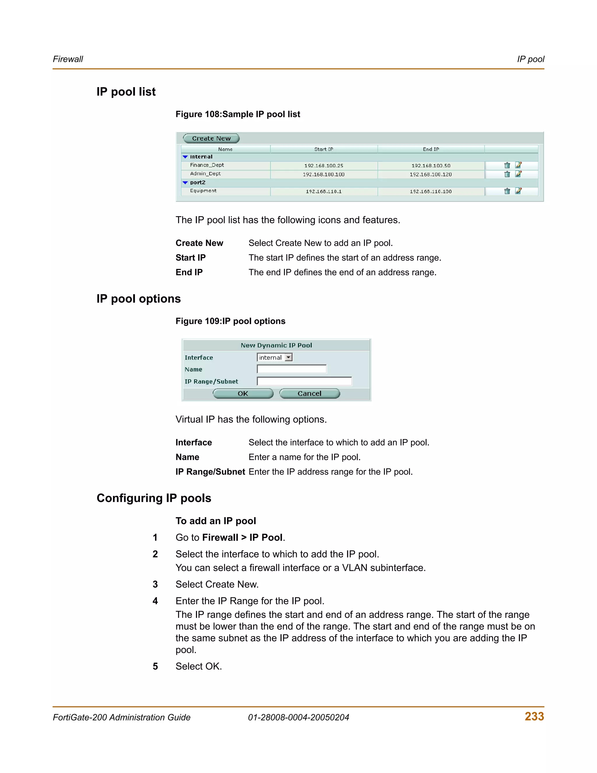
IP pool
An IP pool (also called a dynamic IP pool) is a range of IP addresses added to a
firewall interface. You can enable Dynamic IP Pool in a firewall policy to translate the
source address of outgoing packets to an address randomly selected from the IP pool.
An IP pool list appears when the policy destination interface is the same as the IP pool
interface.
You can add an IP pool if you want to add NAT mode policies that translate source
addresses to addresses randomly selected from the IP pool rather than being limited
to the IP address of the destination interface.
If you add an IP pool to the internal interface, you can select Dynamic IP pool for
policies with the internal interface as the destination. For example, you can add IP
pools to External->Internal and DMZ->Internal policies.
You can add multiple IP pools to any interface and select the IP pool to use when
configuring a firewall policy.
You can enter an IP address range using the following formats.
• x.x.x.x-x.x.x.x, for example 192.168.110.100-192.168.110.120
• x.x.x.[x-x], for example 192.168.110.[100-120]
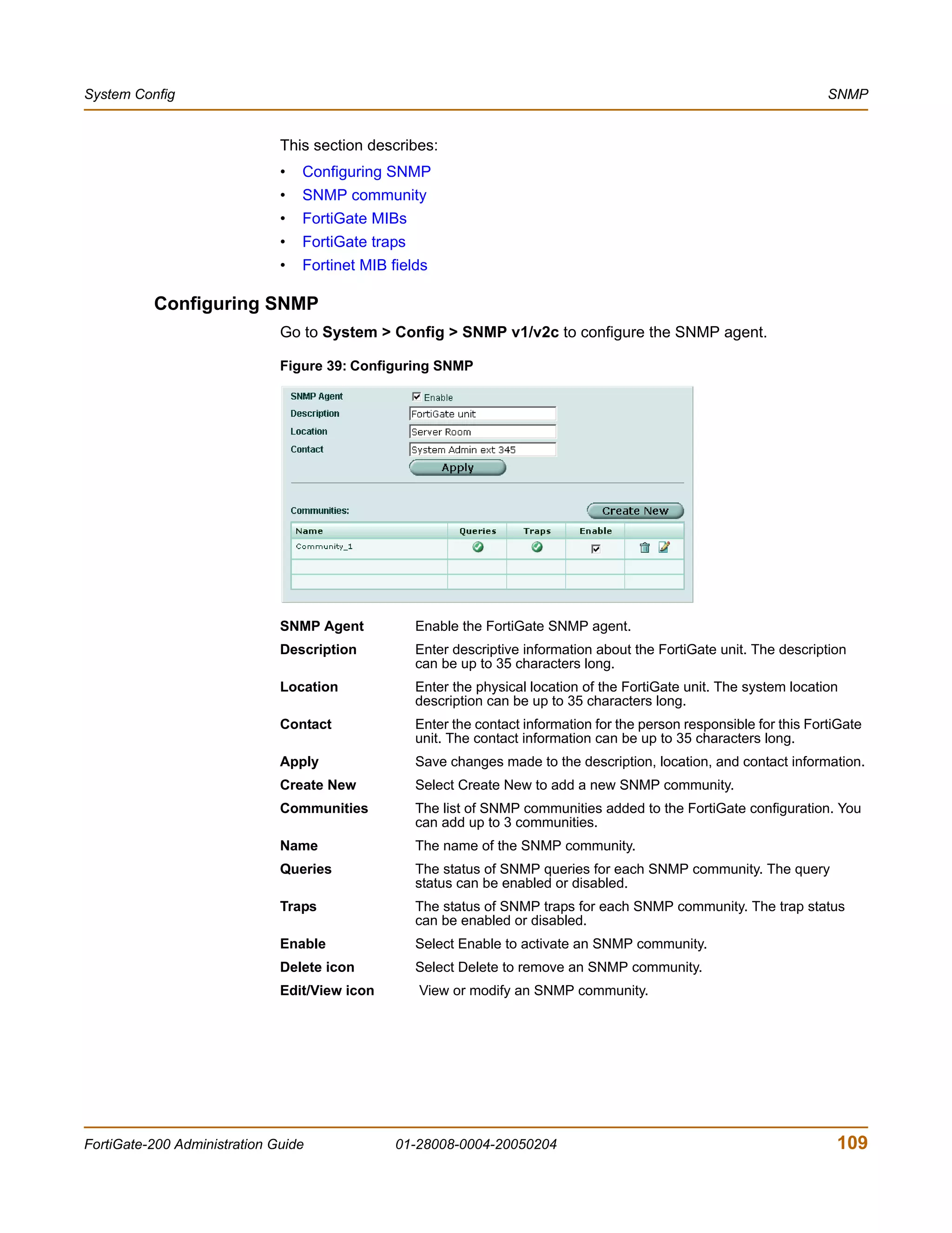
This section describes:
• IP pool list
• IP pool options
• Configuring IP pools
• IP Pools for firewall policies that use fixed ports
• IP pools and dynamic NAT
232 01-28008-0004-20050204 Fortinet Inc.](https://image.slidesharecdn.com/01-28008-0004-20050204fortigate-200administrationguide-121225111736-phpapp02/75/01-28008-0004-20050204-forti-gate-200_administration-guide-232-2048.jpg)
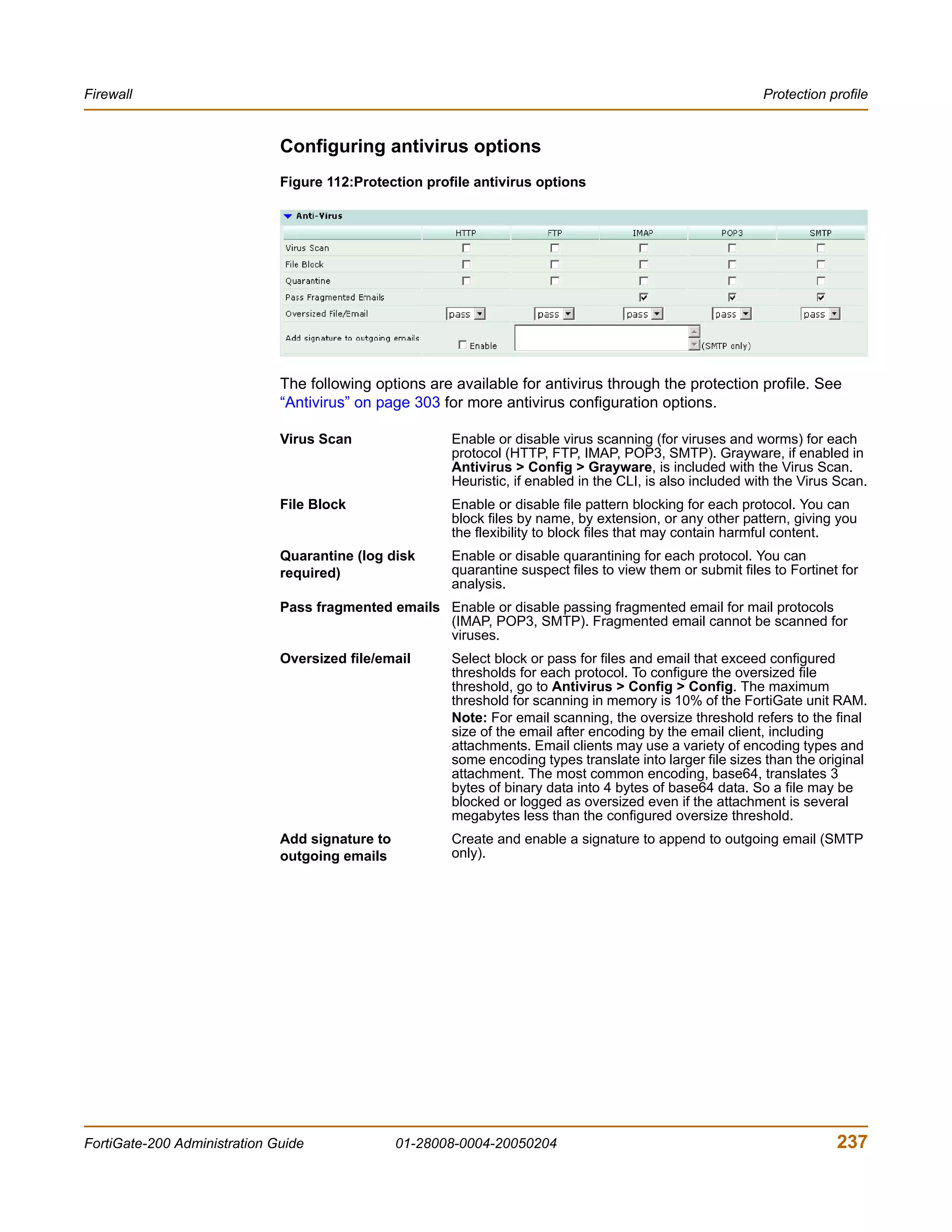
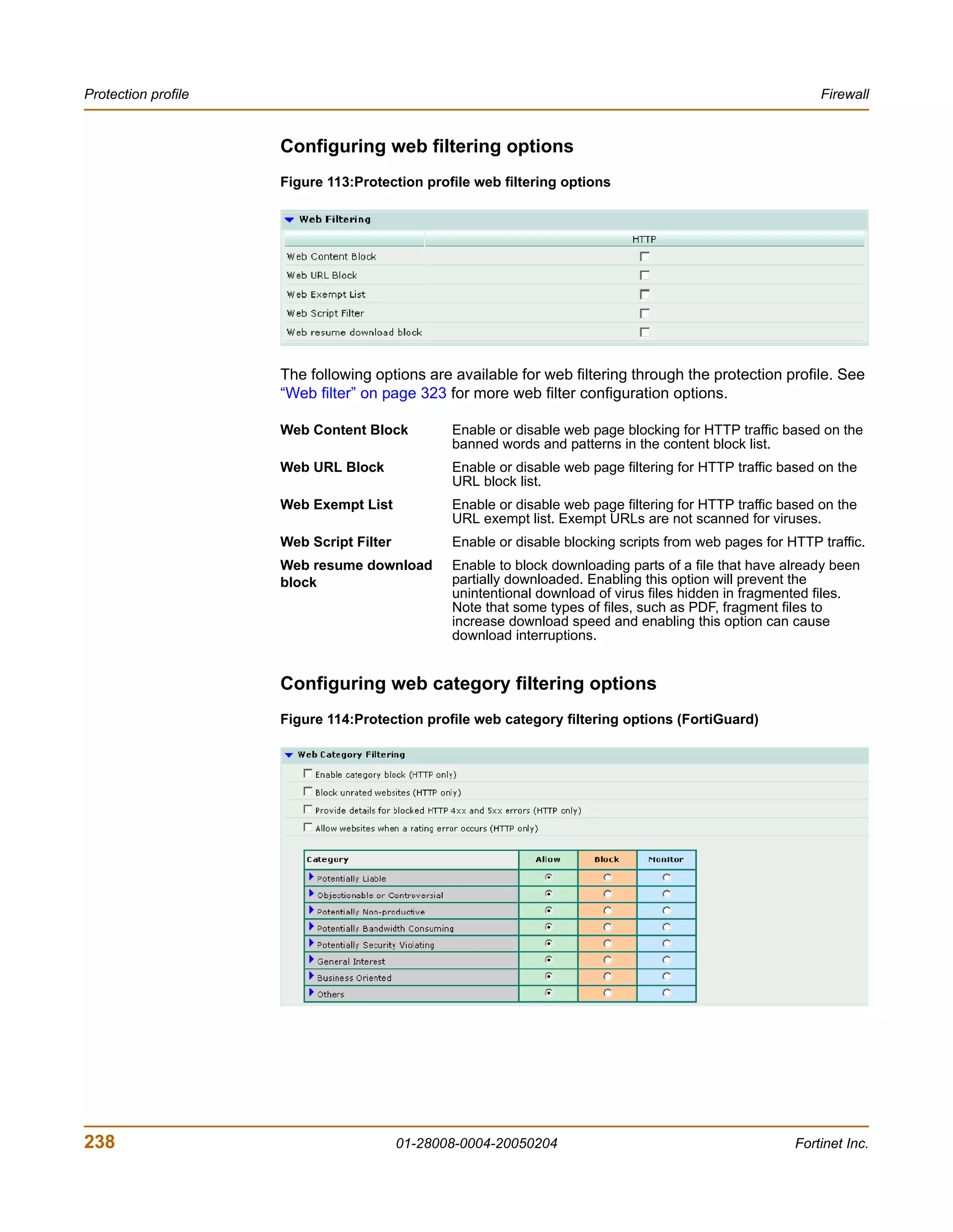

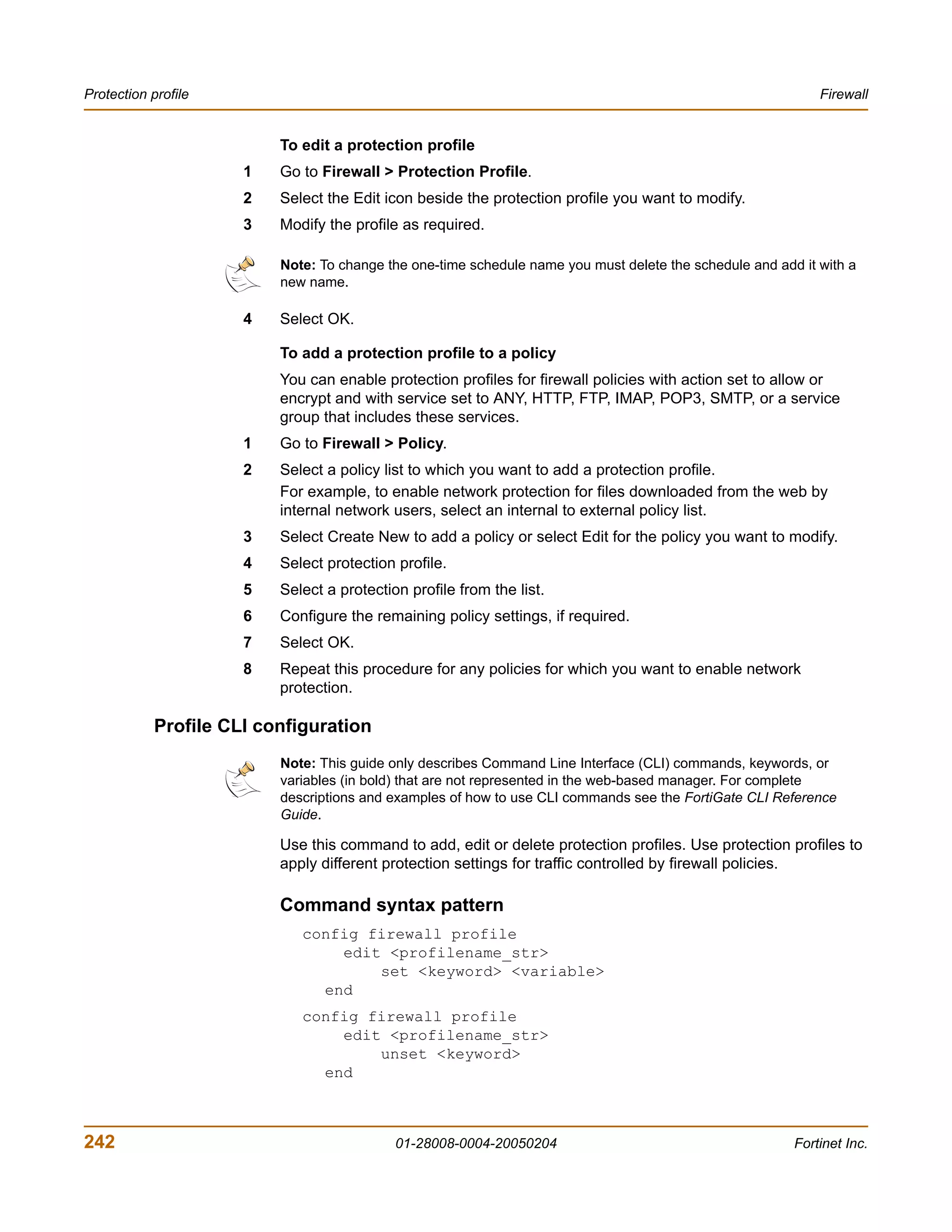
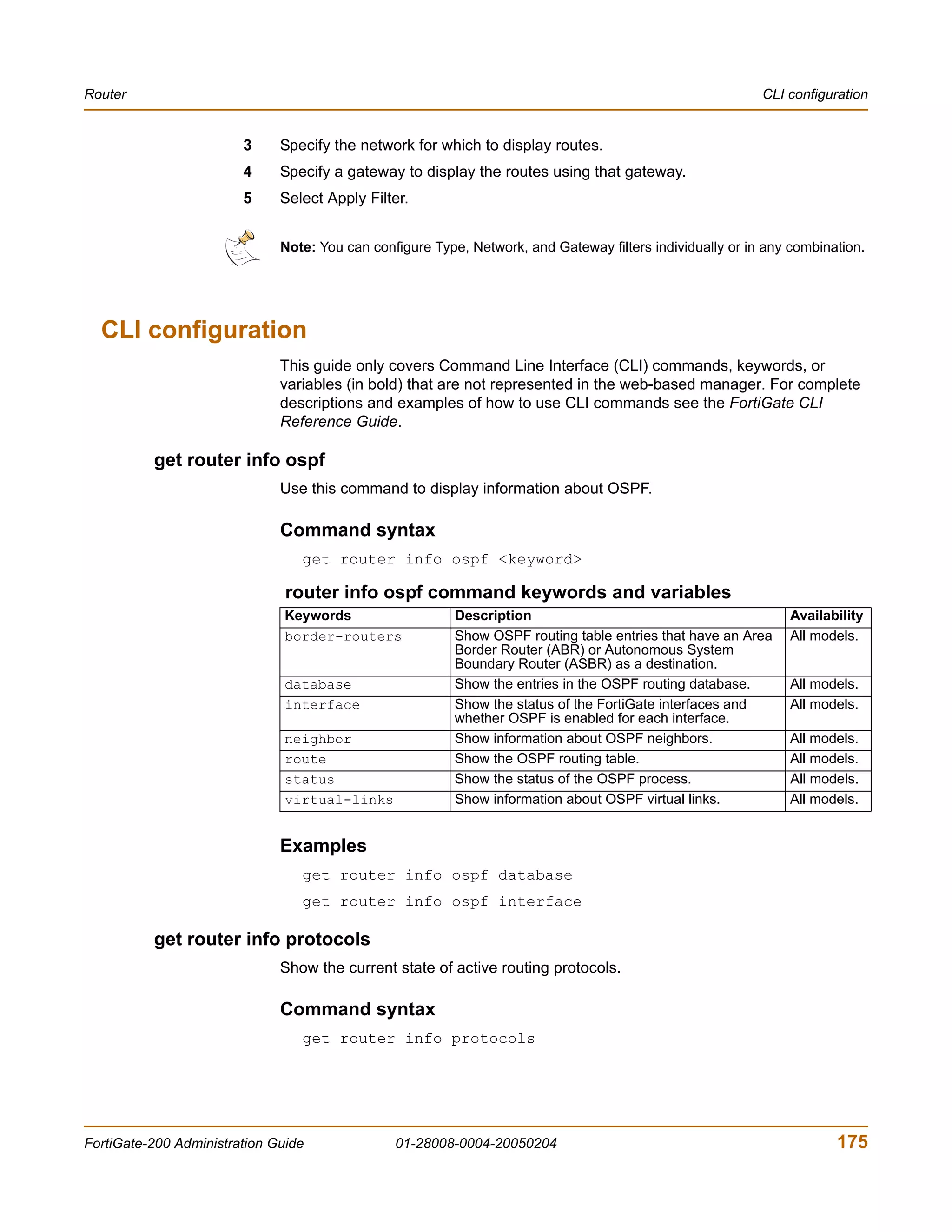
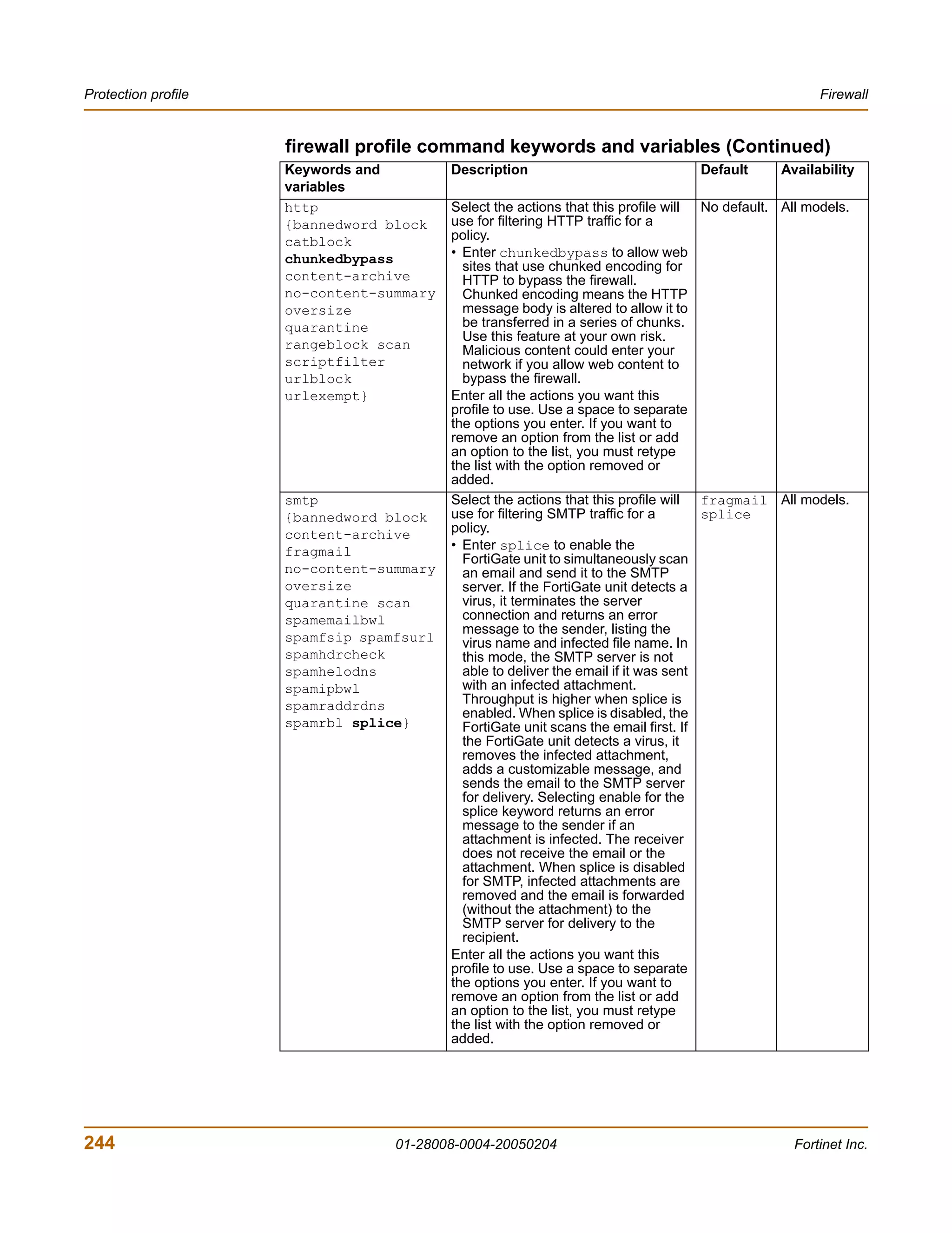
![Firewall Protection profile
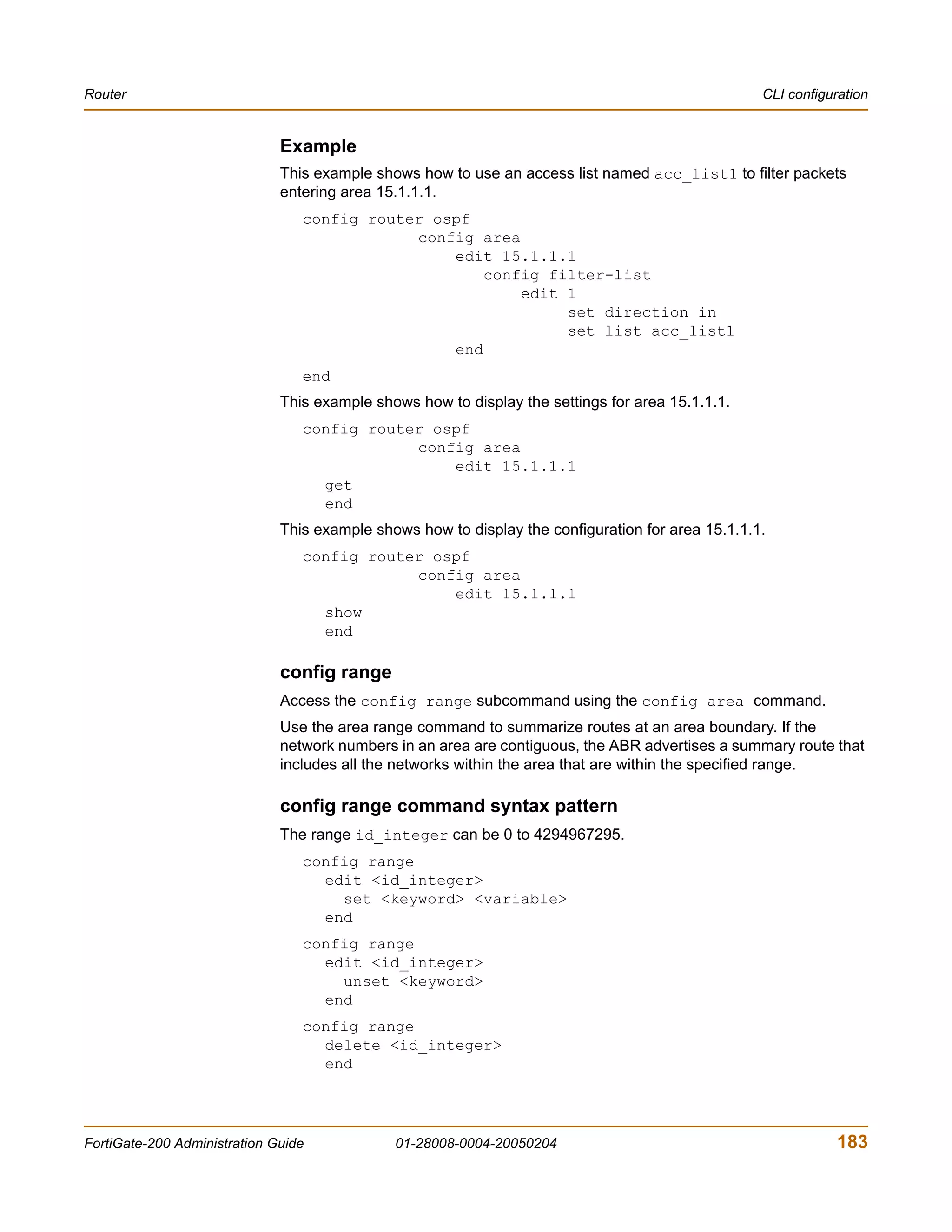
config firewall profile
delete <profilename_str>
end
get firewall profile [<profilename_str>]
show firewall profile [<profilename_str>]
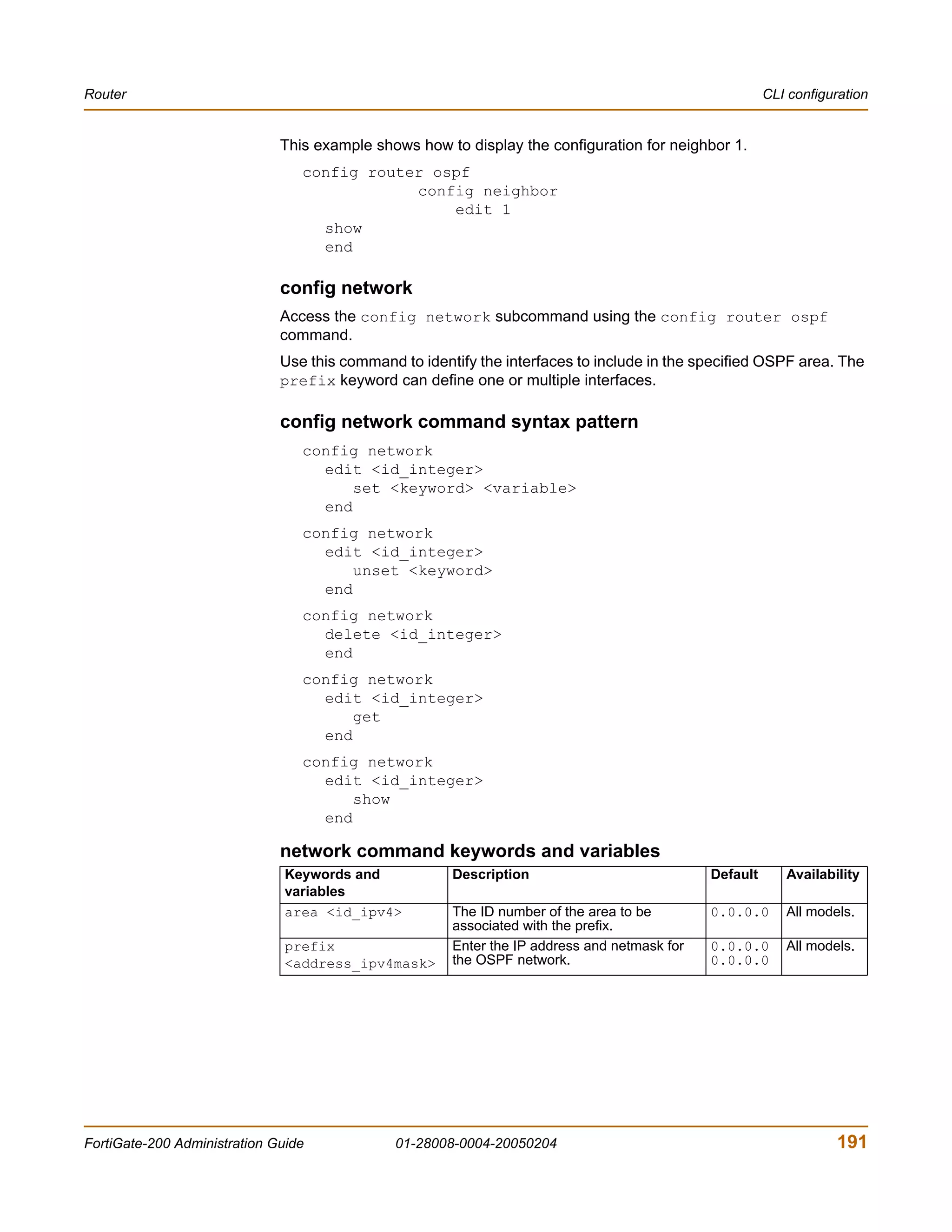
firewall profile command keywords and variables
Keywords and Description Default Availability
variables
ftp Select the actions that this profile will splice All models.
{block use for filtering FTP traffic for a policy.
content-archive • Enter splice to enable the
no-content-summary FortiGate unit to simultaneously
buffer a file for scanning and upload
oversize the file to an FTP server. If a virus is
quarantine scan detected, the FortiGate unit stops the
splice} upload and attempts to delete the
partially uploaded file from the FTP
server. To delete the file successfully,
the server permissions must be set
to allow deletes. When downloading
files from an FTP server the
FortiGate unit sends 1 byte every 30
seconds to prevent the client from
timing out during scanning and
download. If a virus is detected, the
FortiGate unit stops the download.
The user must then delete the
partially downloaded file. There
should not be enough content in the
file to cause any harm. Enabling
splice reduces timeouts when
uploading and downloading large
files. When splice is disabled for ftp,
the FortiGate unit buffers the file for
scanning before uploading it to the
FTP server. If the file is clean, the
FortiGate unit will allow the upload to
continue.
Enter all the actions you want this
profile to use. Use a space to separate
the options you enter. If you want to
remove an option from the list or add
an option to the list, you must retype
the list with the option removed or
added.
FortiGate-200 Administration Guide 01-28008-0004-20050204 243](https://image.slidesharecdn.com/01-28008-0004-20050204fortigate-200administrationguide-121225111736-phpapp02/75/01-28008-0004-20050204-forti-gate-200_administration-guide-243-2048.jpg)

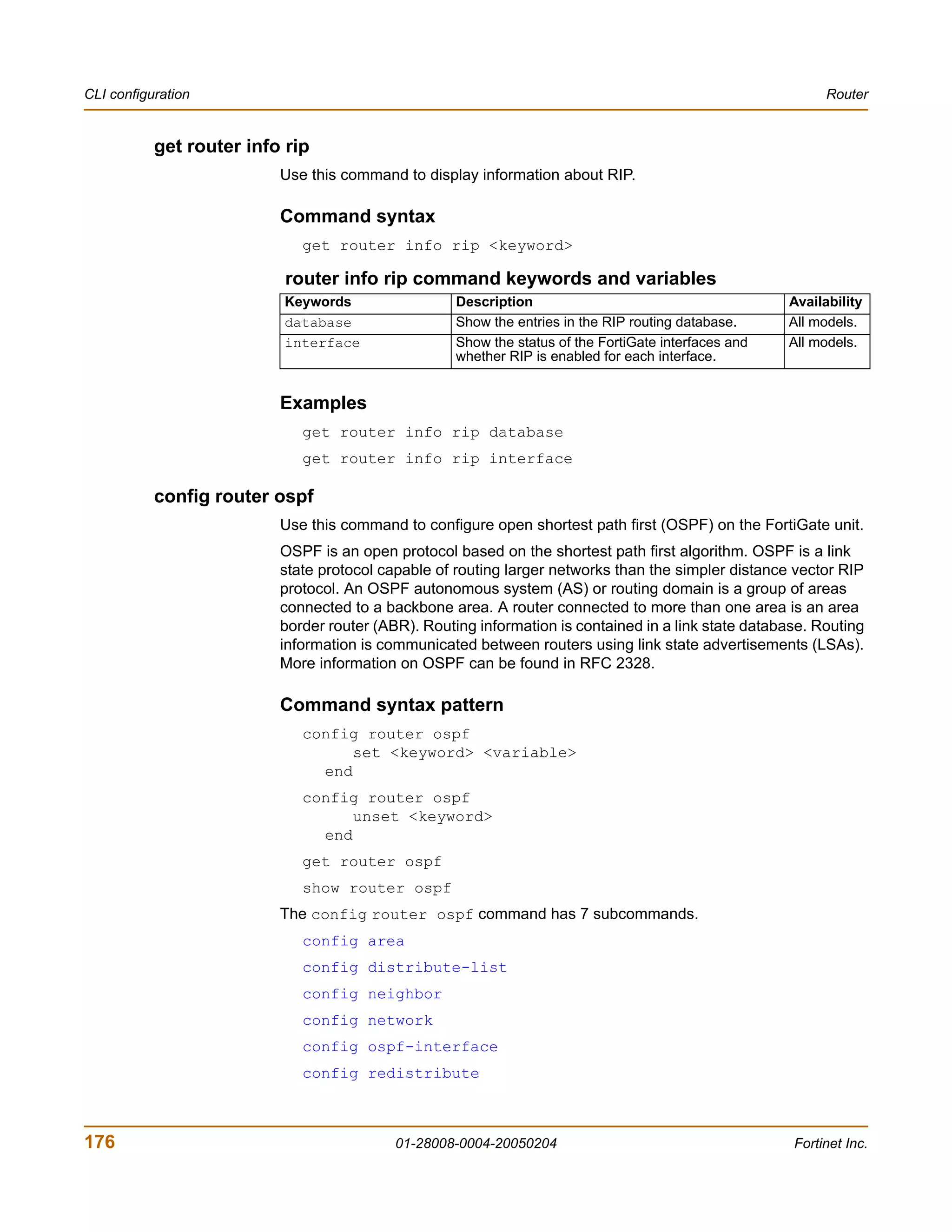
![User CLI configuration
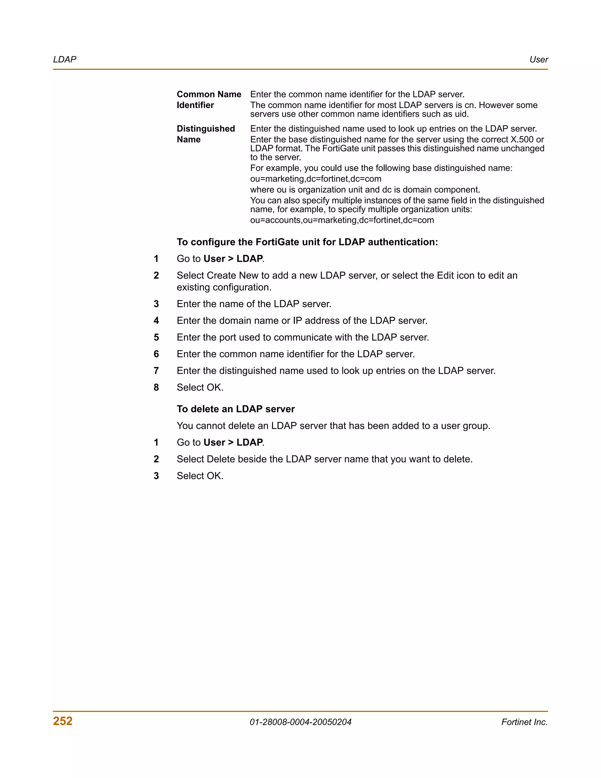
To delete a user group
You cannot delete a user group that is included in a firewall policy, a dialup user
phase 1 configuration, or a PPTP or L2TP configuration.
1 Go to User > User Group.
2 Select Delete beside the user group that you want to delete.
3 Select OK.
CLI configuration
This guide only covers Command Line Interface (CLI) commands that are not
represented in the web-based manager. For complete descriptions and examples of
how to use CLI commands see the FortiGate CLI Reference Guide.
peer
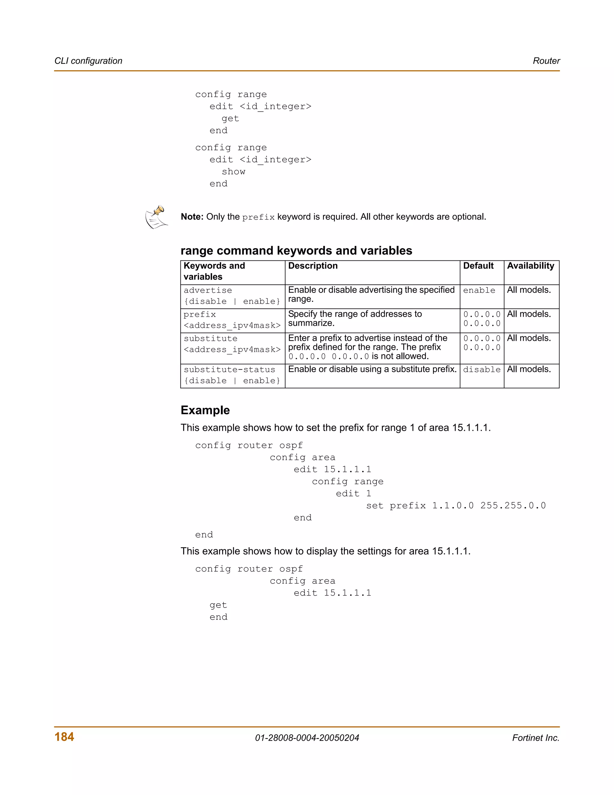
Use this command to add or edit the peer certificate information.
Command syntax pattern
config user peer
edit <name_str>
set <keyword> <variable>
config user peer
edit <name_str>
unset <keyword>
config user peer
delete <name_str>
get user peer [<name_str>]
show user peer [<name_str>]
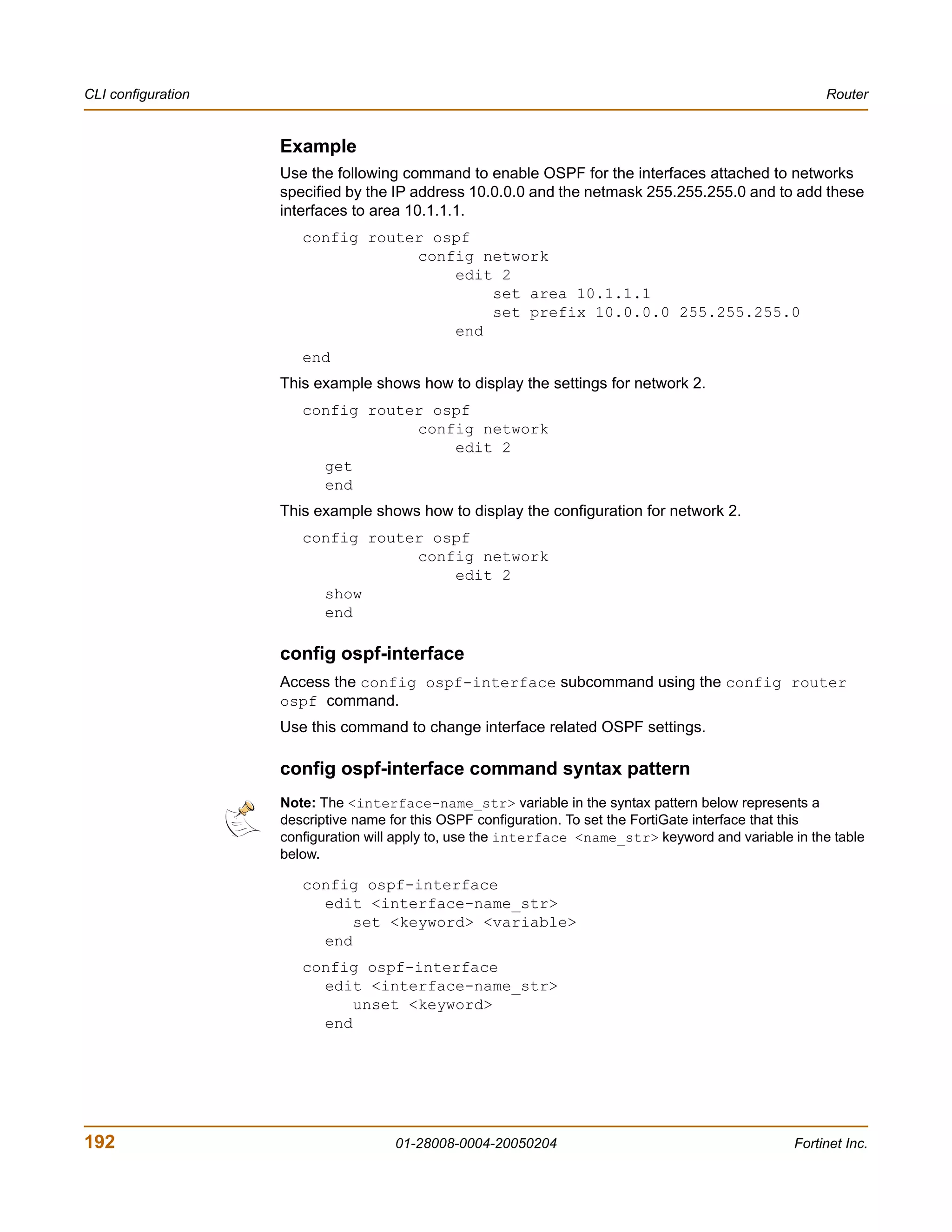
radius command keywords and variables
Keywords and variables Description Default Availability
ca Enter the peer Certificate Authority No default. All models.
(CA).
cn Enter the peer certificate common No default. All models.
name.
cn-type {FDQN | email Enter the peer certificate common string All models.
| ipv4 | string} name type.
subject Enter the peer certificate name No default. All models.
constraints.
FortiGate-200 Administration Guide 01-28008-0004-20050204 255](https://image.slidesharecdn.com/01-28008-0004-20050204fortigate-200administrationguide-121225111736-phpapp02/75/01-28008-0004-20050204-forti-gate-200_administration-guide-255-2048.jpg)
![CLI configuration User
Example
This example shows how to add the branch_office peer.
config user peer
edit branch_office
set ca
set cn
set cn-type
end
This example shows how to display the list of configured peers.
get user peer
This example shows how to display the settings for the peer branch_office.
get user peer branch_office
This example shows how to display the configuration for all the peers.
show user peer
This example shows how to display the configuration for the peer branch_office.
show user peer branch_office
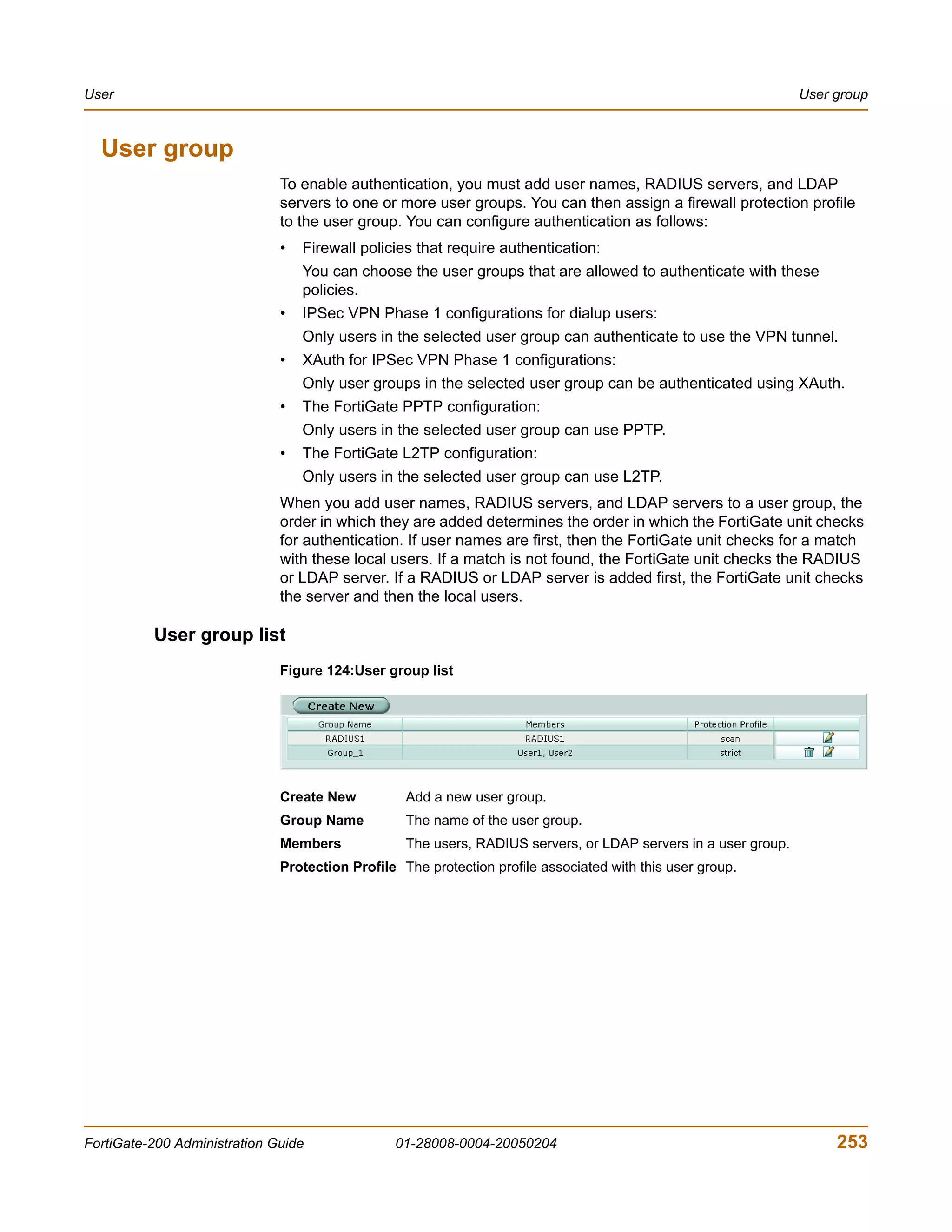
peergrp
Use this command to add or edit a peer group.
Command syntax pattern
config user peergrp
edit <name_str>
set <keyword> <variable>
config user peergrp
edit <name_str>
unset <keyword>
config user peergrp
delete <name_str>
get user peergrp [<name_str>]
show user peergrp [<name_str>]
radius command keywords and variables
Keywords and variables Description Default Availability
member <name_str> Enter the names of peers to add No default. All models.
[<name_str> [<name_str> to the peer group. Separate
[<name_str> ... ]]] names by spaces. To add or
remove names from the group
you must re-enter the whole list
with the additions or deletions
required.
256 01-28008-0004-20050204 Fortinet Inc.](https://image.slidesharecdn.com/01-28008-0004-20050204fortigate-200administrationguide-121225111736-phpapp02/75/01-28008-0004-20050204-forti-gate-200_administration-guide-256-2048.jpg)

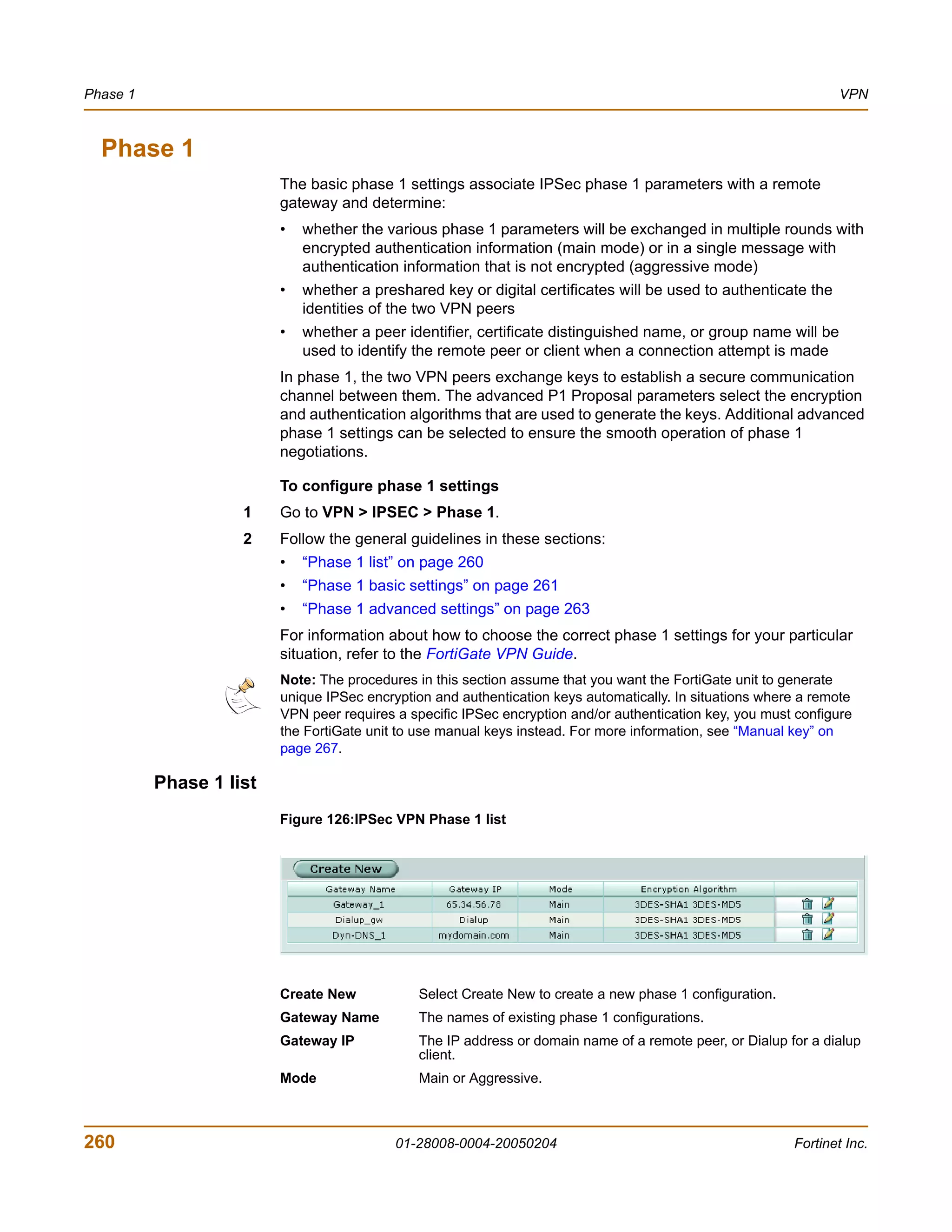
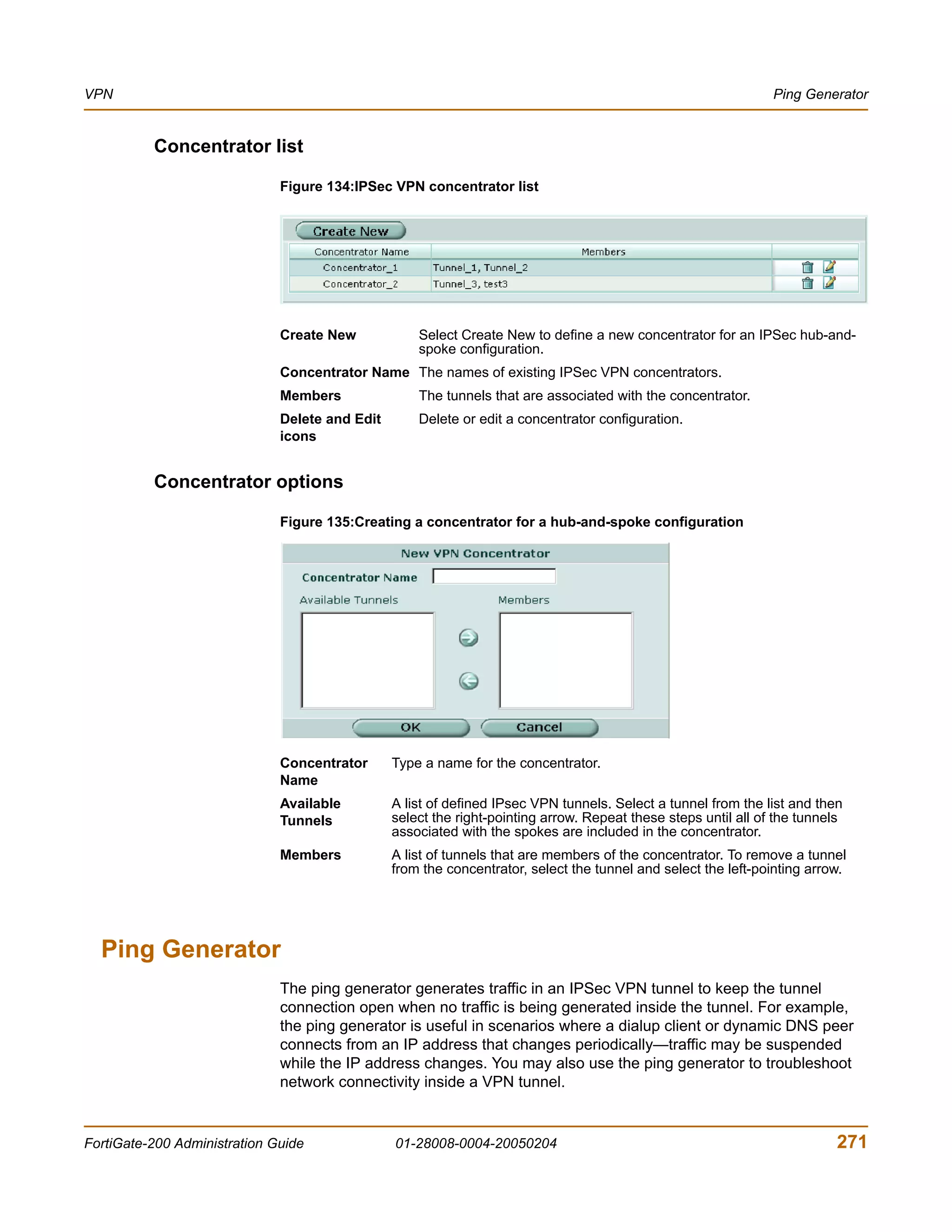
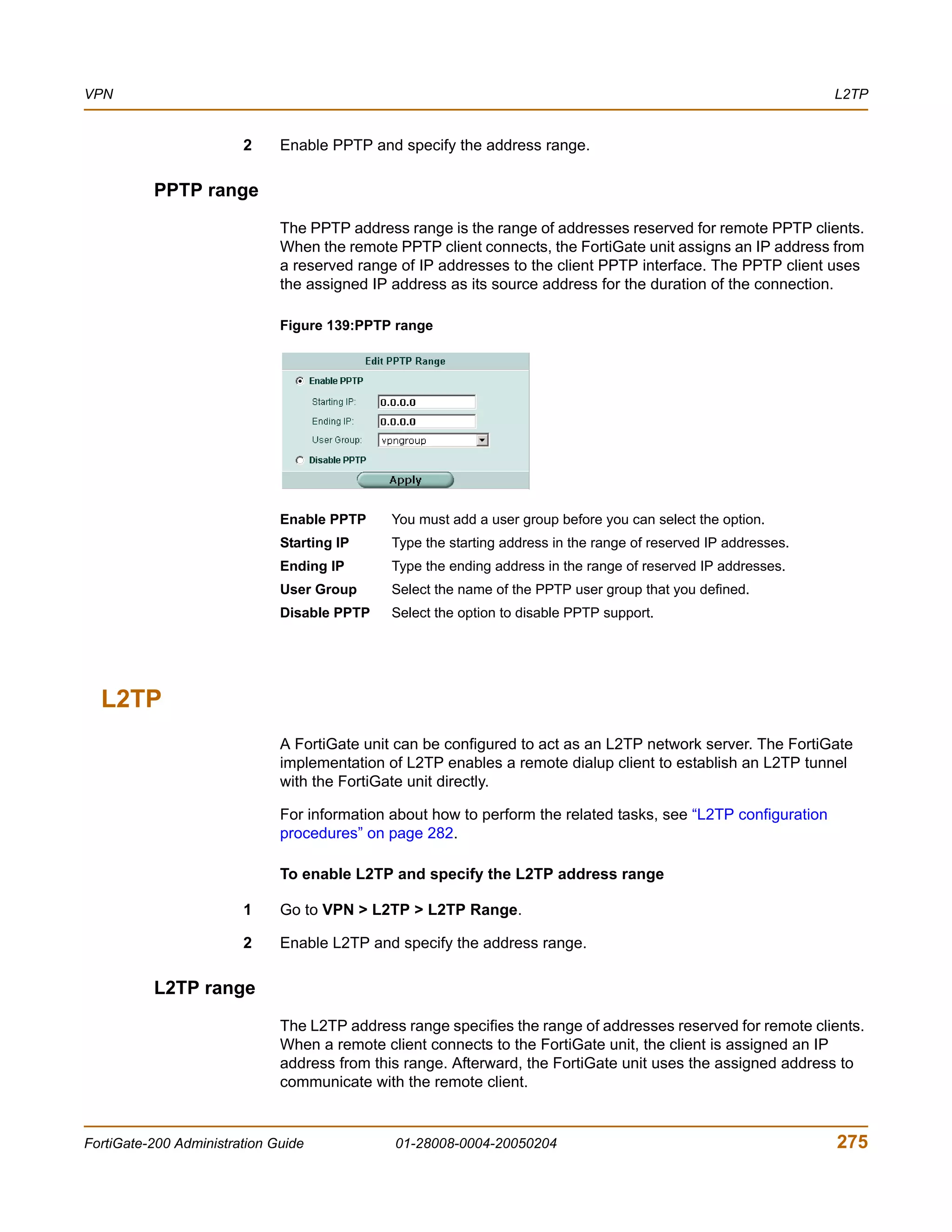
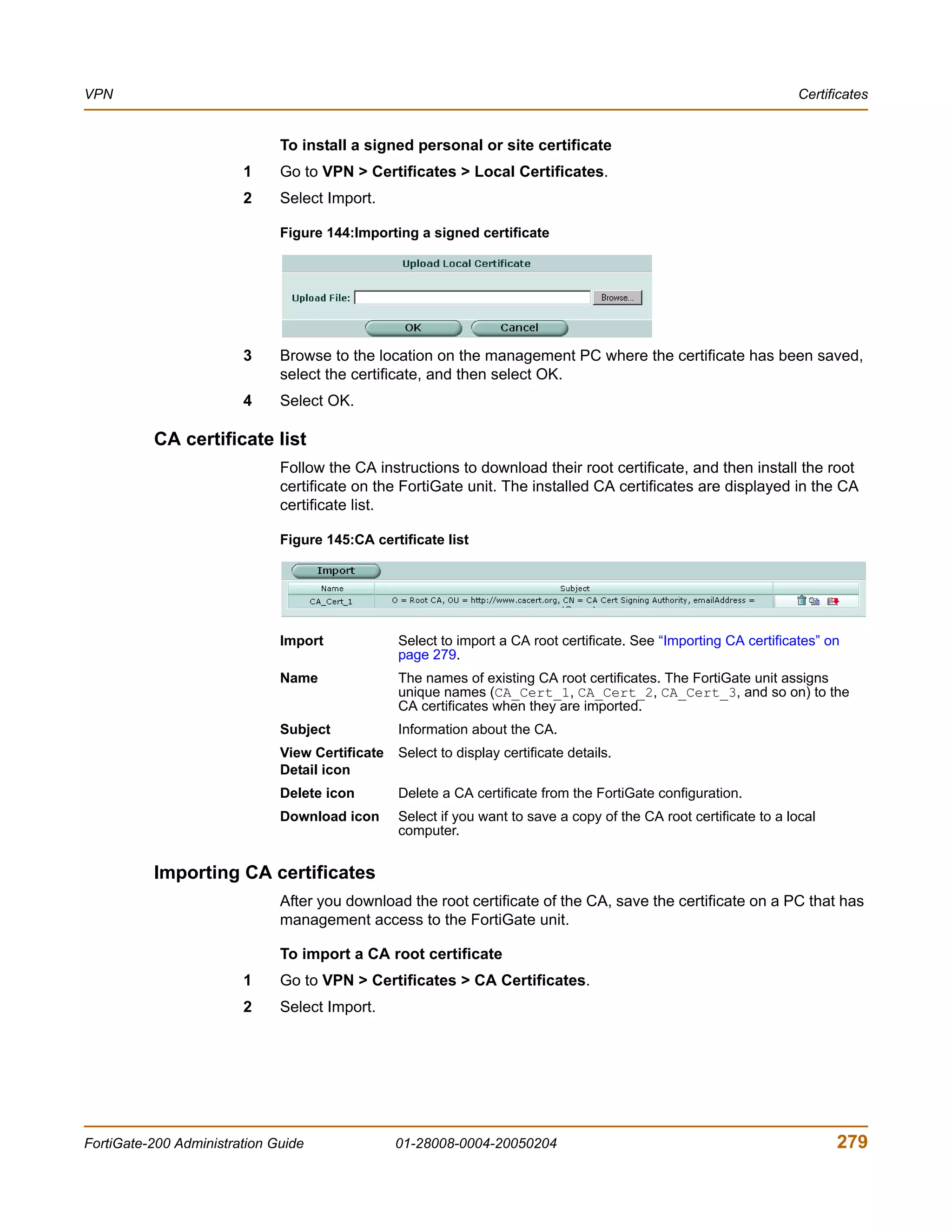
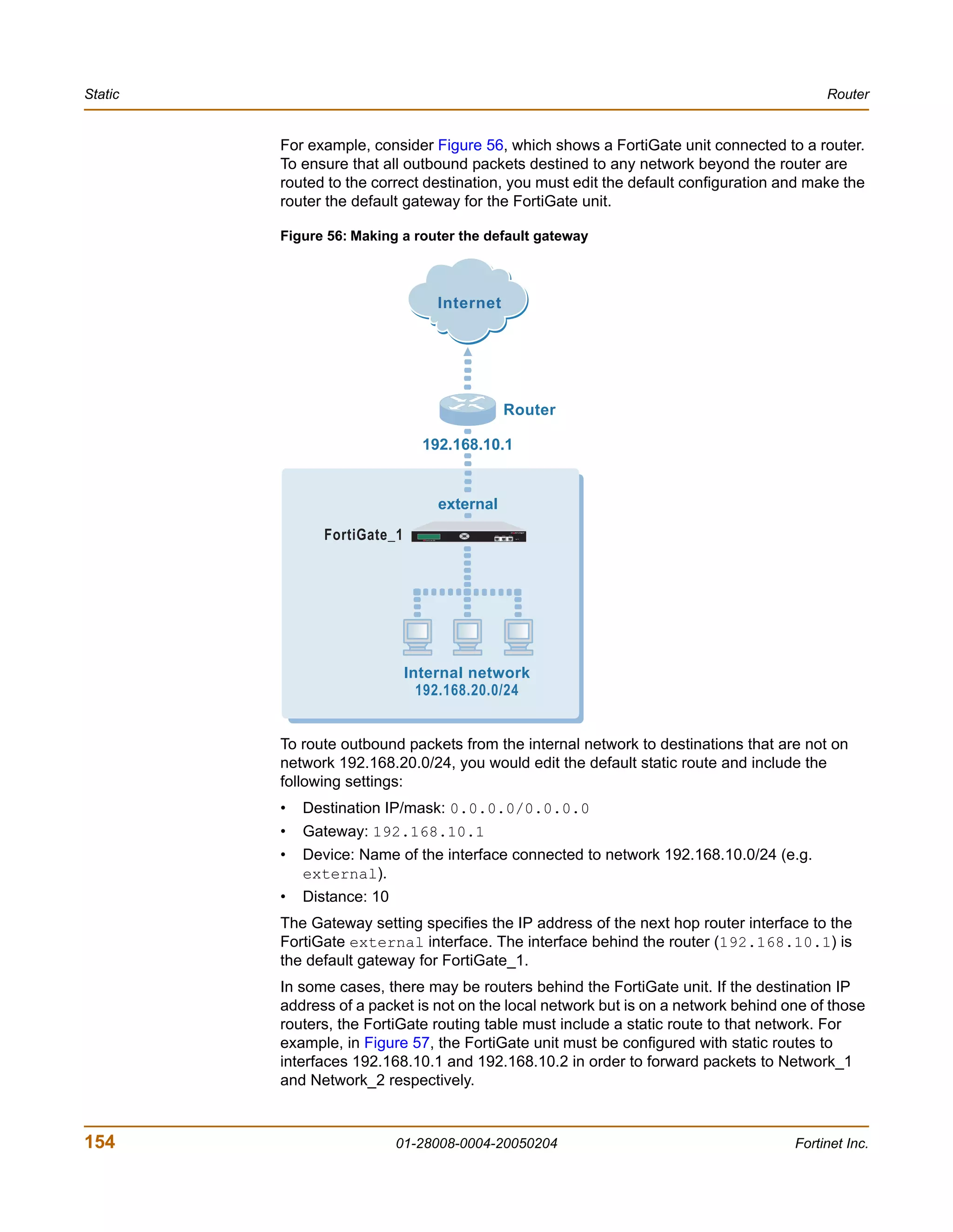
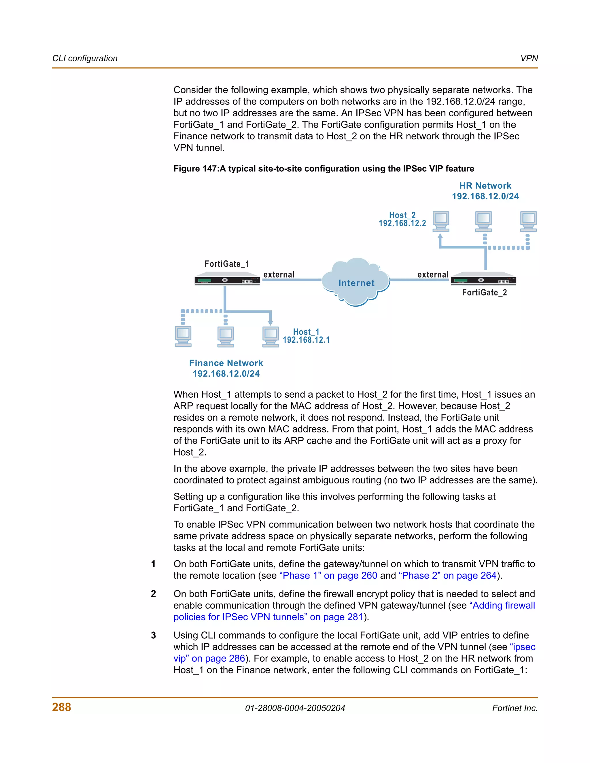
![VPN VPN configuration procedures
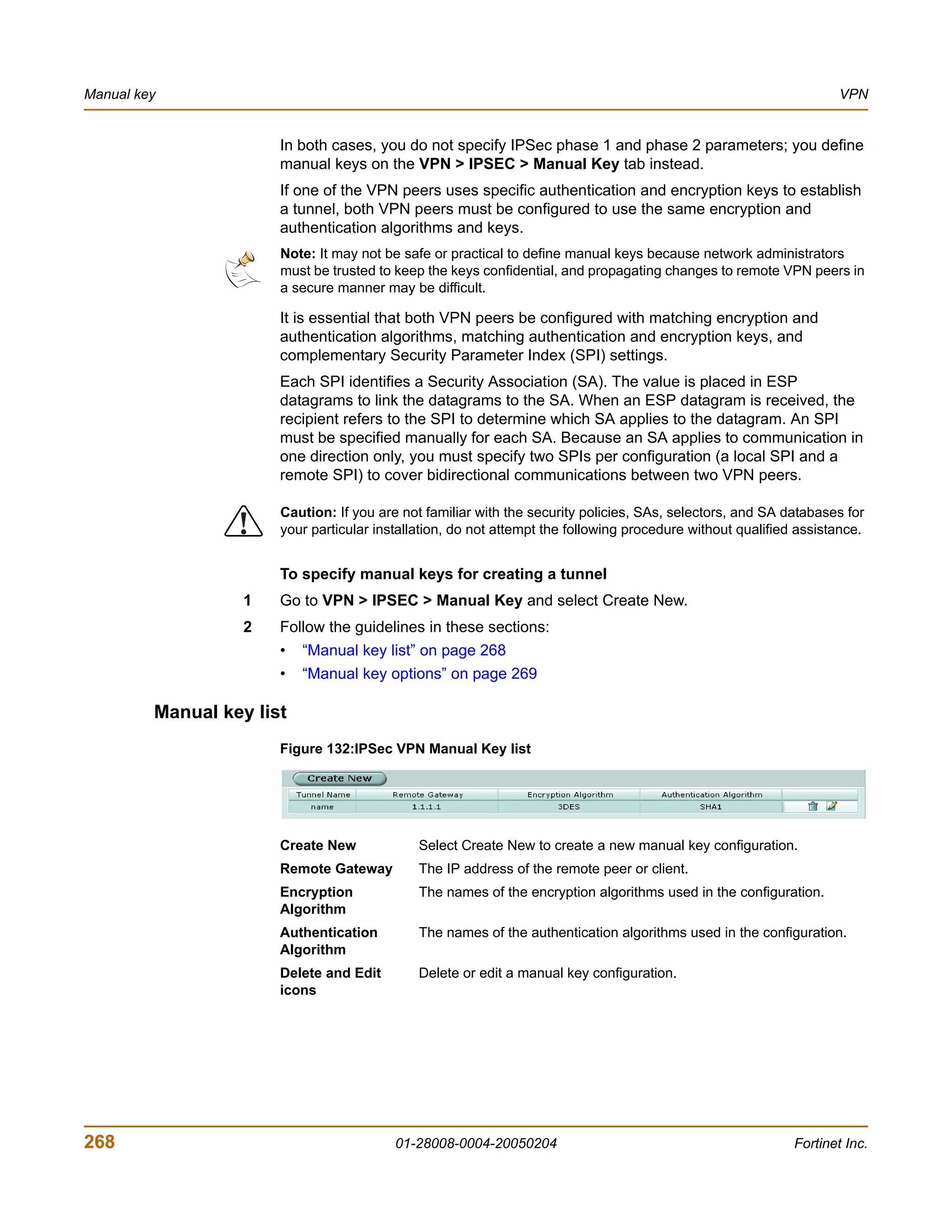
Adding firewall policies for IPSec VPN tunnels
Firewall policies control all IP traffic passing between a source address and a
destination address. A firewall encryption policy is needed to allow the transmission of
encrypted packets, specify the permitted direction of VPN traffic, and select the VPN
tunnel that will be subject to the policy. A single encryption policy is needed to control
both inbound and outbound IP traffic through a VPN tunnel.
Before you define the policy, you must first specify the IP source and destination
addresses.
To define an IP source address
1 Go to Firewall > Address and select Create New.
2 In the Address Name field, type a name that represents the local network, server(s),
or host(s) from which IP packets may originate on the private network behind the local
FortiGate unit.
3 In the IP Range/Subnet field, type the corresponding IP address and subnet mask (for
example, 172.16.5.0/24 for a subnet, or 172.16.5.1/32 for a server or host) or
IP address range (for example, 192.168.10.[80-100]).
4 Select OK.
To define an IP destination address
1 Go to Firewall > Address and select Create New.
2 In the Address Name field, type a name that represents the remote network, server(s),
or host(s) to which IP packets may be delivered.
3 In the IP Range/Subnet field, type the corresponding IP address and subnet mask (for
example, 192.168.20.0/24 for a subnet, or 192.168.20.2/32 for a server or
host), or IP address range (for example, 192.168.20.[10-25]).
4 Select OK.
To define the firewall encryption policy
1 Go to Firewall > Policy and select Create New.
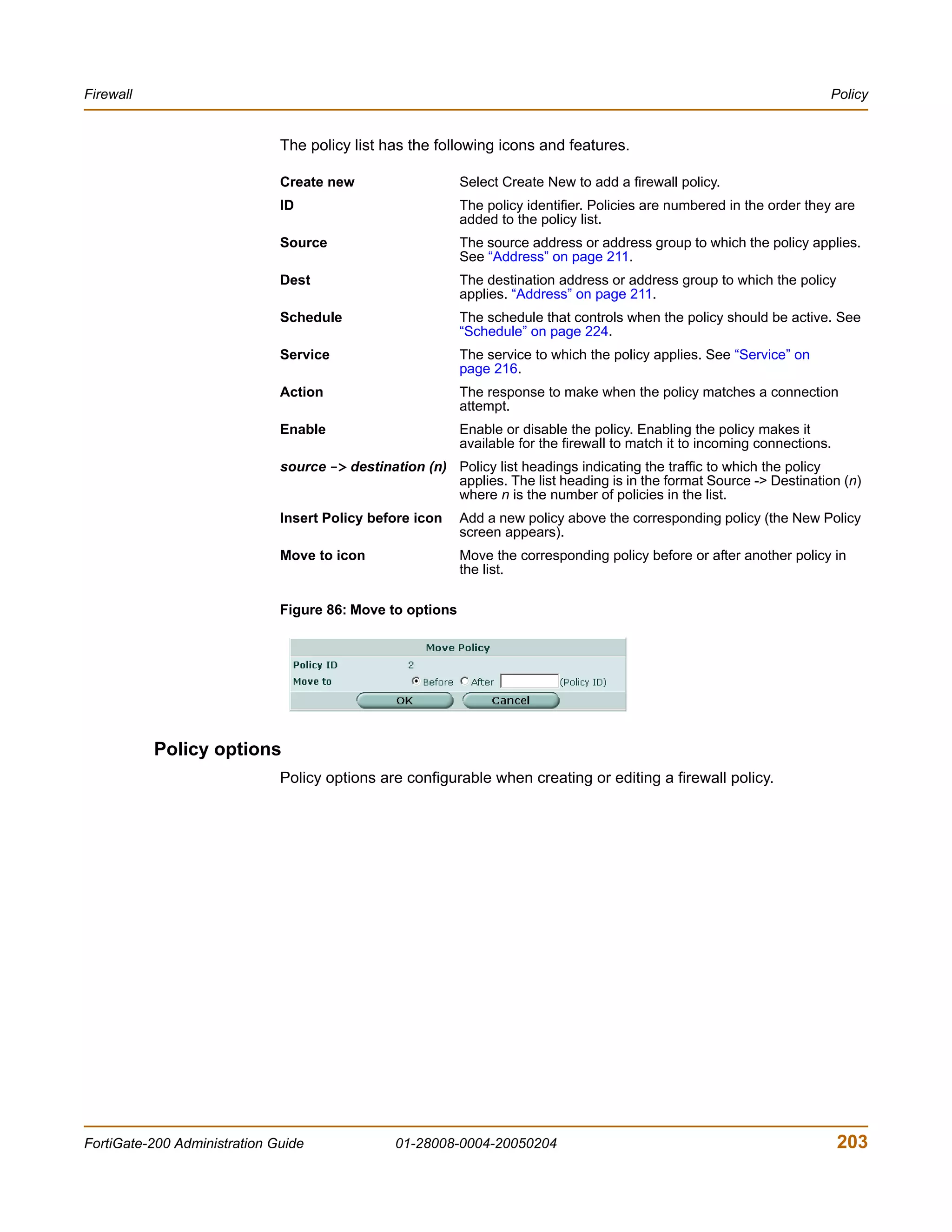
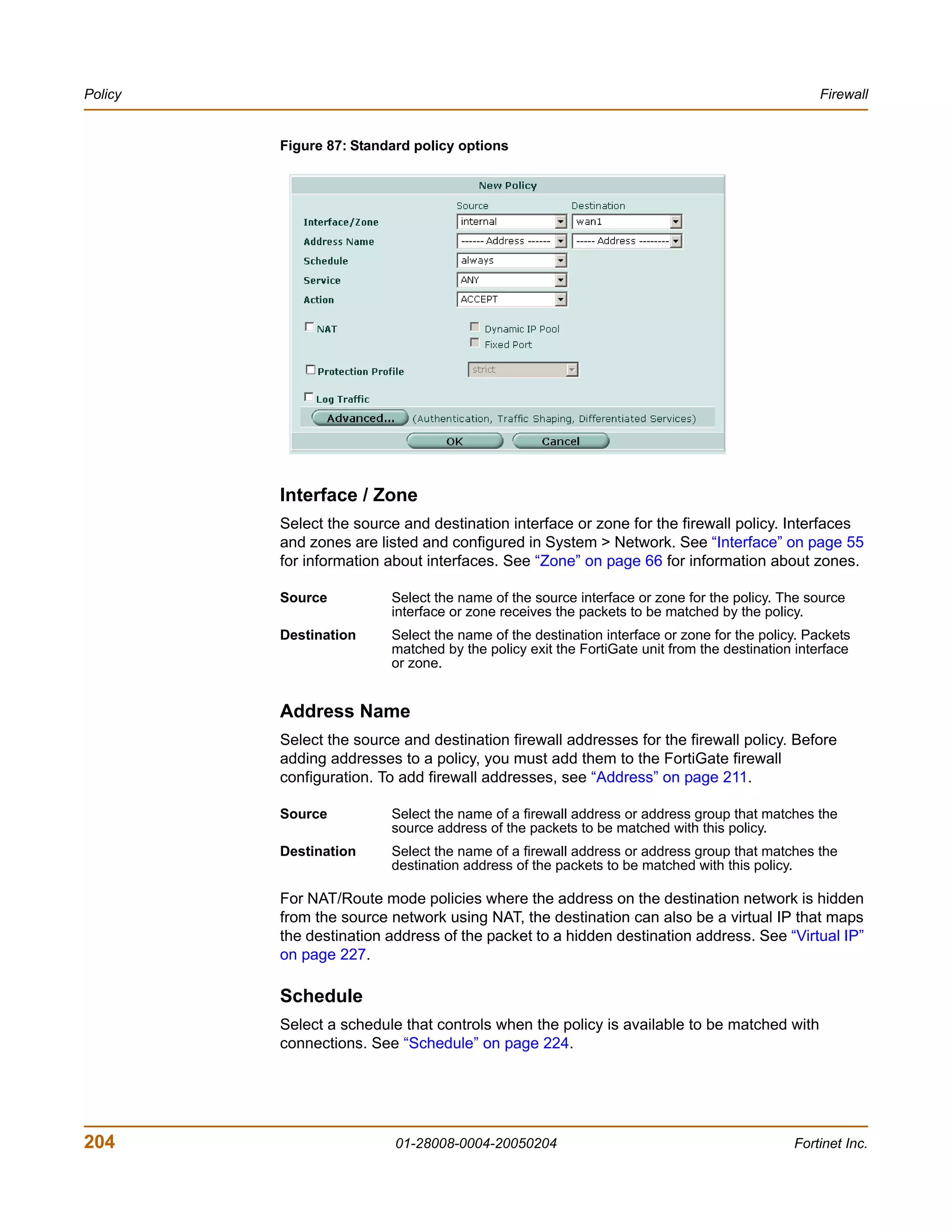
2 Include appropriate entries as follows:
Interface/Zone Source
Select the local interface to the internal (private) network.
Destination
Select the local interface to the external (public) network.
Address Name Source
Select the name that corresponds to the local network, server(s), or
host(s) from which IP packets may originate.
Destination
Select the name that corresponds to the remote network, server(s), or
host(s) to which IP packets may be delivered. The name may correspond
to a VIP-address range for dialup clients.
Schedule Keep the default setting (always) unless changes are needed to meet
specific requirements.
Service Keep the default setting (ANY) unless changes are needed to meet your
specific requirements.
FortiGate-200 Administration Guide 01-28008-0004-20050204 281](https://image.slidesharecdn.com/01-28008-0004-20050204fortigate-200administrationguide-121225111736-phpapp02/75/01-28008-0004-20050204-forti-gate-200_administration-guide-281-2048.jpg)
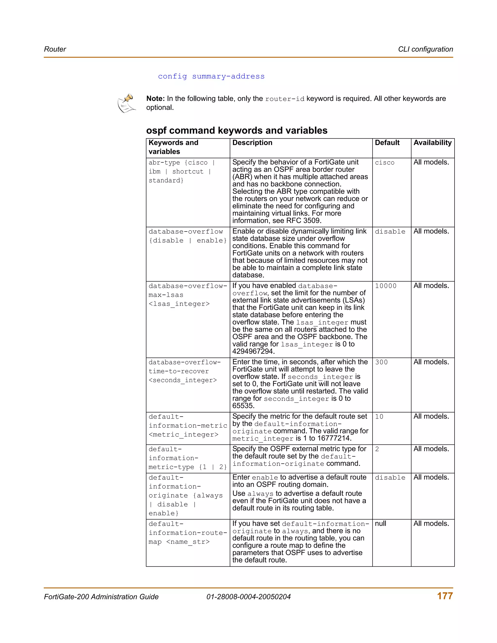
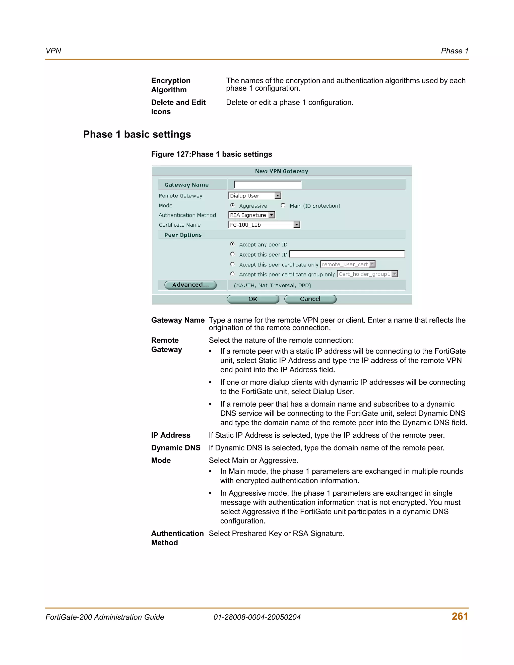
![CLI configuration VPN
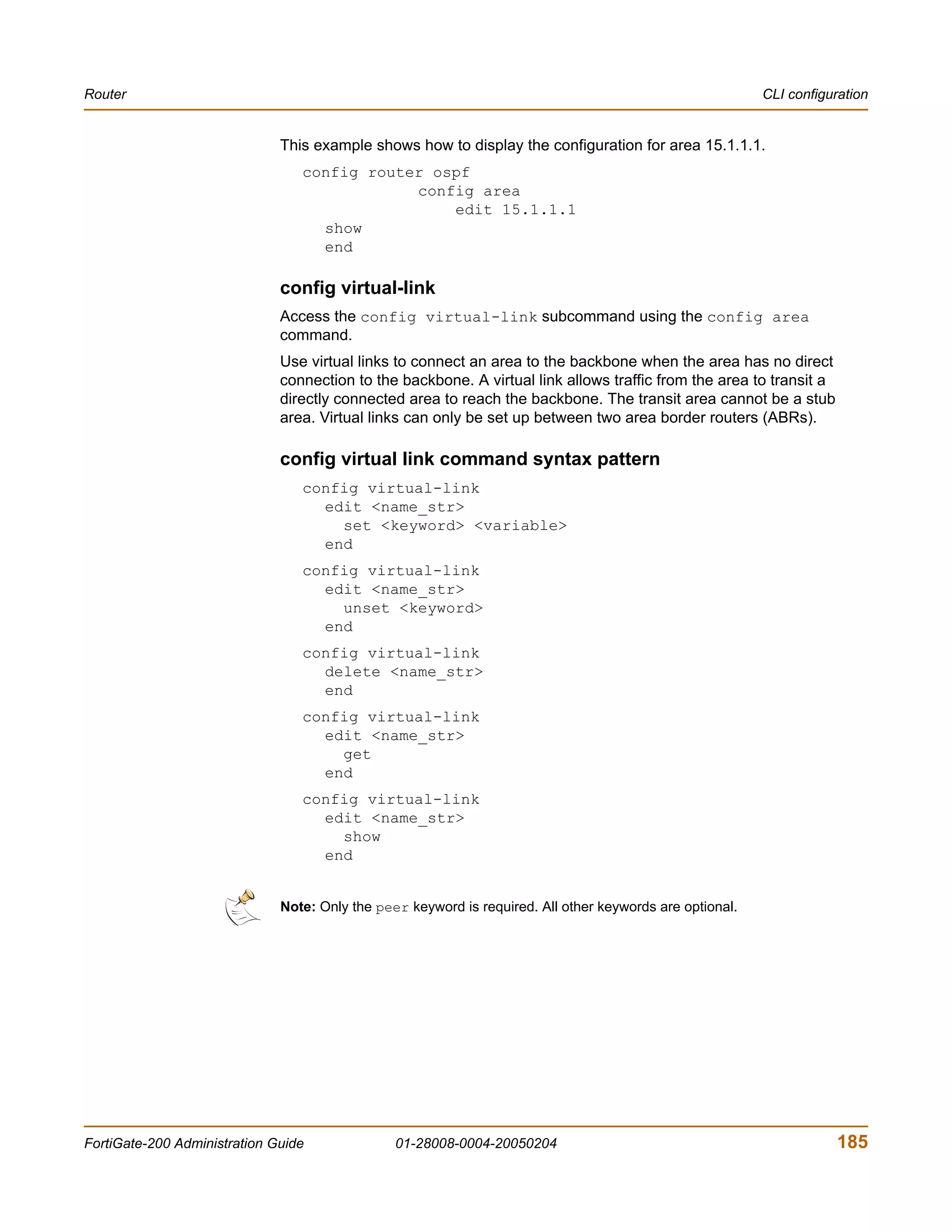
get vpn ipsec phase2 [<name_str>]
show vpn ipsec phase2 [<name_str>]
ipsec phase2 command keywords and variables
Keywords and variables Description Default Availability
bindtoif Bind the tunnel to the specified null All models.
<interface-name_str> network interface. Type the name of
the local FortiGate interface.
single-source Enable or disable all dialup clients to disable All models.
{disable | enable} connect using the same phase 2
tunnel definition.
ipsec vip
A FortiGate unit can act as a proxy by answering ARP requests locally and forwarding
the associated traffic to the intended destination host over an IPSec VPN tunnel. The
feature is intended to enable IPSec VPN communications between two hosts that
coordinate the same private address space on physically separate networks. The IP
addresses of both the source host and the destination host must be unique. The
ipsec vip command lets you specify the IP addresses that can be accessed at the
remote end of the VPN tunnel. You must configure IPSec virtual IP (VIP) addresses at
both ends of the IPSec VPN tunnel.
Adding an IPSec VIP entry to the VIP table enables a FortiGate unit to respond to
ARP requests destined for remote servers and route traffic to the intended
destinations automatically. Each IPSec VIP entry is identified by an integer. An entry
identifies the name of the FortiGate interface to the destination network, and the IP
address of a destination host on the destination network. Specify an IP address for
every host that needs to be accessed on the other side of the tunnel—you can define
a maximum of 32 IPSec VIP addresses on the same interface.
Note: The interface to the destination network must be associated with a VPN tunnel through a
firewall encryption policy (action must be set to encrypt). The policy determines which VPN
tunnel will be selected to forward traffic to the destination. When you create IPSec VIP entries,
check the encryption policy on the FortiGate interface to the destination network to ensure that
it meets your requirements.
For more information, see “Configuring IPSec virtual IP addresses” on page 287.
Command syntax pattern
config vpn ipsec vip
edit <vip_integer>
set <keyword> <variable>
end
config vpn ipsec vip
edit <vip_integer>
unset <keyword>
end
config vpn ipsec vip
delete <vip_integer>
end
286 01-28008-0004-20050204 Fortinet Inc.](https://image.slidesharecdn.com/01-28008-0004-20050204fortigate-200administrationguide-121225111736-phpapp02/75/01-28008-0004-20050204-forti-gate-200_administration-guide-286-2048.jpg)
![VPN CLI configuration
get vpn ipsec vip [<vip_integer>]
show vpn ipsec vip [<vip_integer>]
ipsec vip command keywords and variables
Keywords and variables
Description Default Availability
ip <address_ipv4> The IP address of the destination 0.0.0.0 All models.
host on the destination network.
out-interface The name of the FortiGate interface null All models.
<interface-name_str> to the destination network.
Example
The following commands add IPSec VIP entries for two remote hosts that can be
accessed by a FortiGate unit through an IPSec VPN tunnel on the external
interface of the FortiGate unit. Similar commands must be entered on the FortiGate
unit at the other end of the IPSec VPN tunnel.
config vpn ipsec vip
edit 1
set ip 192.168.12.1
set out-interface external
next
edit 2
set ip 192.168.12.2
set out-interface external
end
Note: Typing next lets you define another VIP address without leaving the vip shell.
This example shows how to display the settings for the vpn ipsec vip command.
get vpn ipsec vip
This example shows how to display the settings for the VIP entry named 1.
get vpn ipsec vip 1
This example shows how to display the current configuration of all existing VIP
entries.
show vpn ipsec vip
Configuring IPSec virtual IP addresses
Use the FortiGate unit’s IPSec VIP feature to enable hosts on physically different
networks to communicate with each other as if they were connected to the same
private network. This feature can be configured manually through CLI commands.
When the destination IP address in a local ARP request matches an entry in the
FortiGate unit’s virtual IP (VIP) table, the FortiGate unit responds with its own MAC
address and forwards traffic to the correct destination at the other end of the VPN
tunnel afterward.
FortiGate-200 Administration Guide 01-28008-0004-20050204 287](https://image.slidesharecdn.com/01-28008-0004-20050204fortigate-200administrationguide-121225111736-phpapp02/75/01-28008-0004-20050204-forti-gate-200_administration-guide-287-2048.jpg)

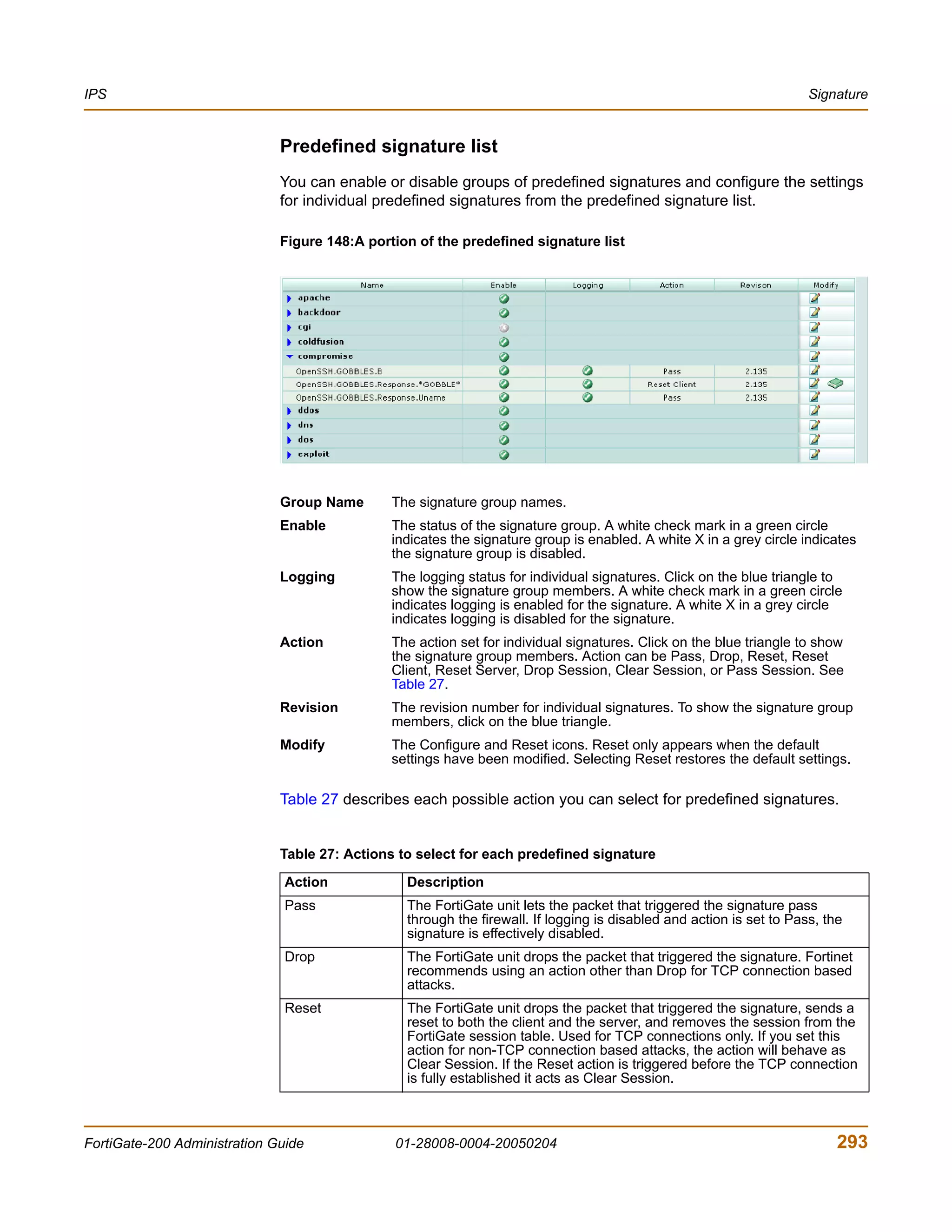
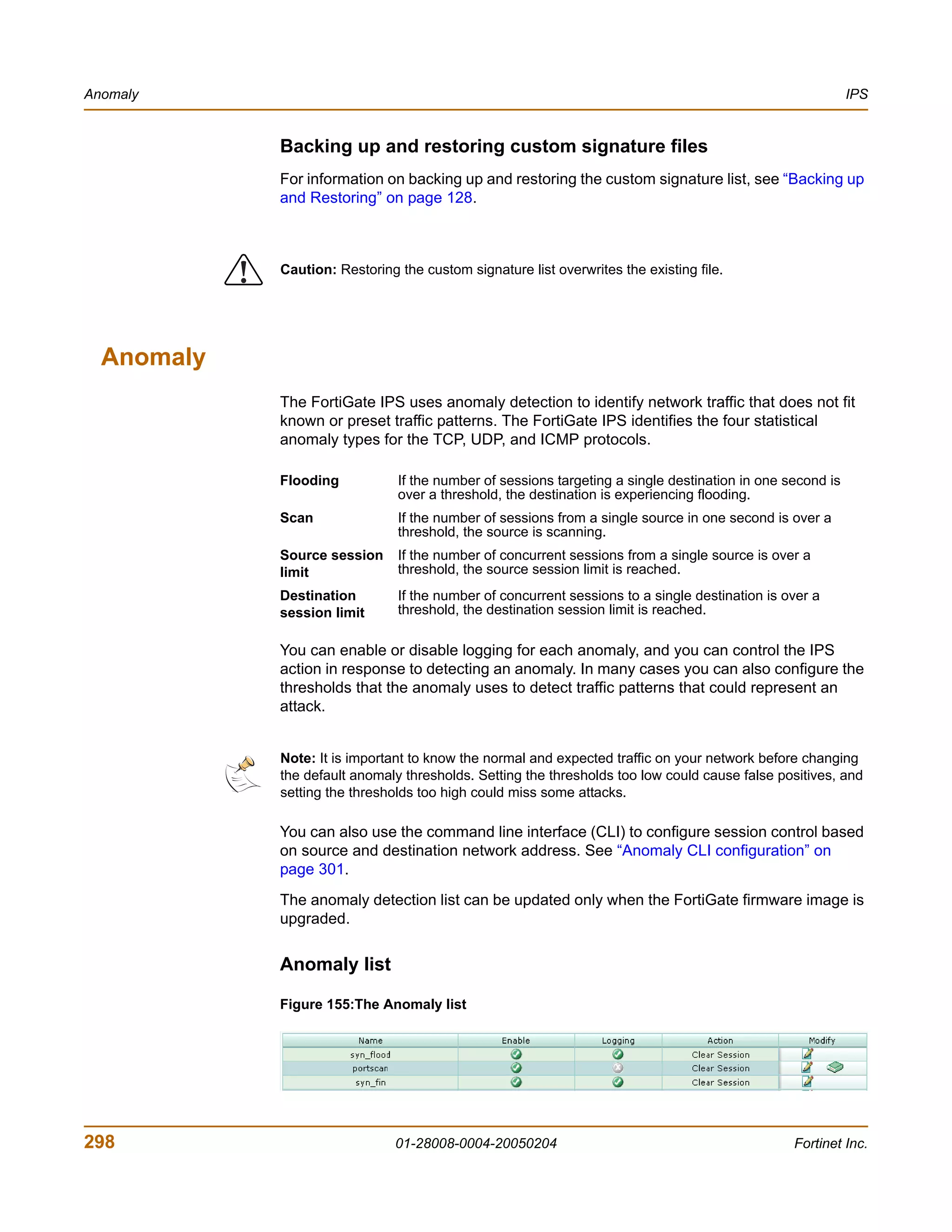
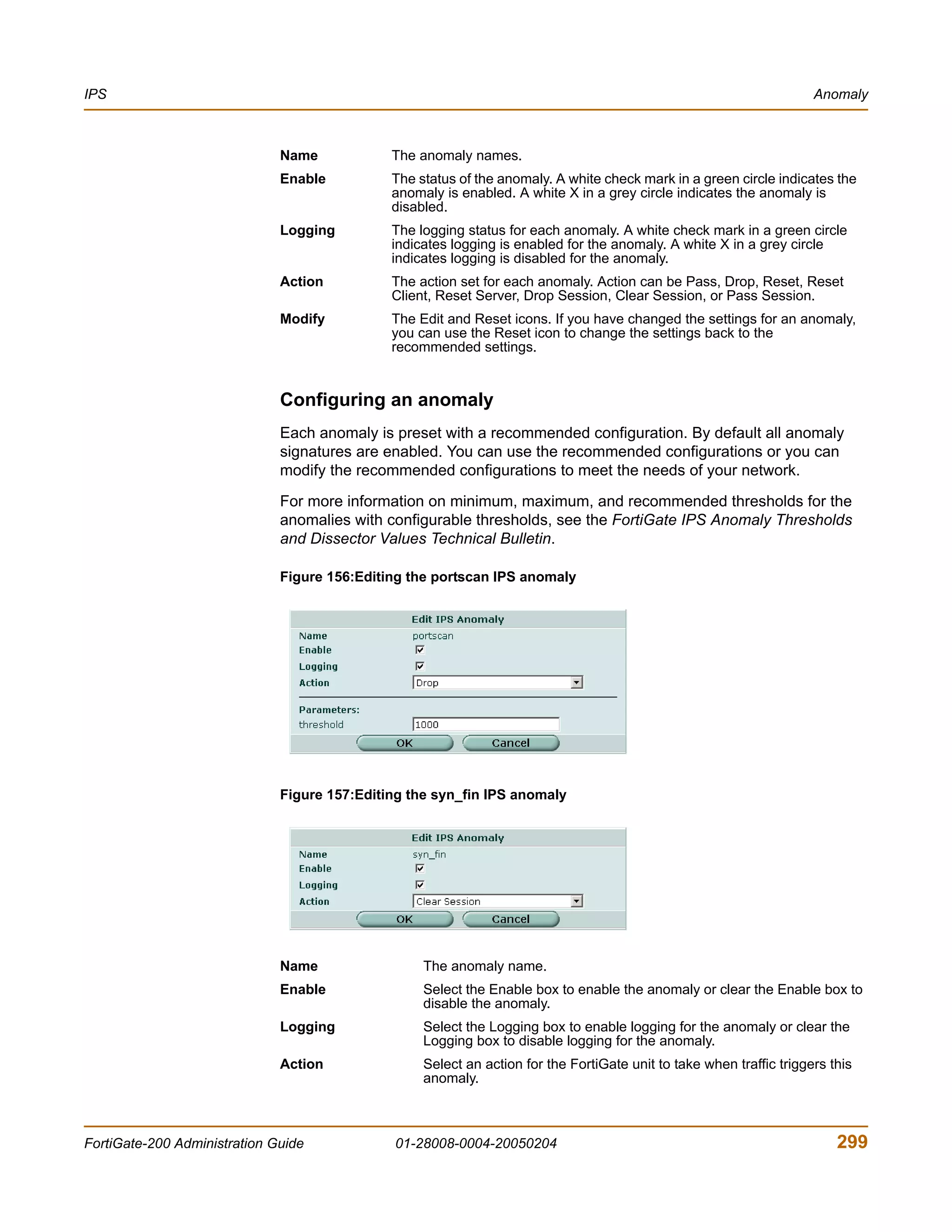
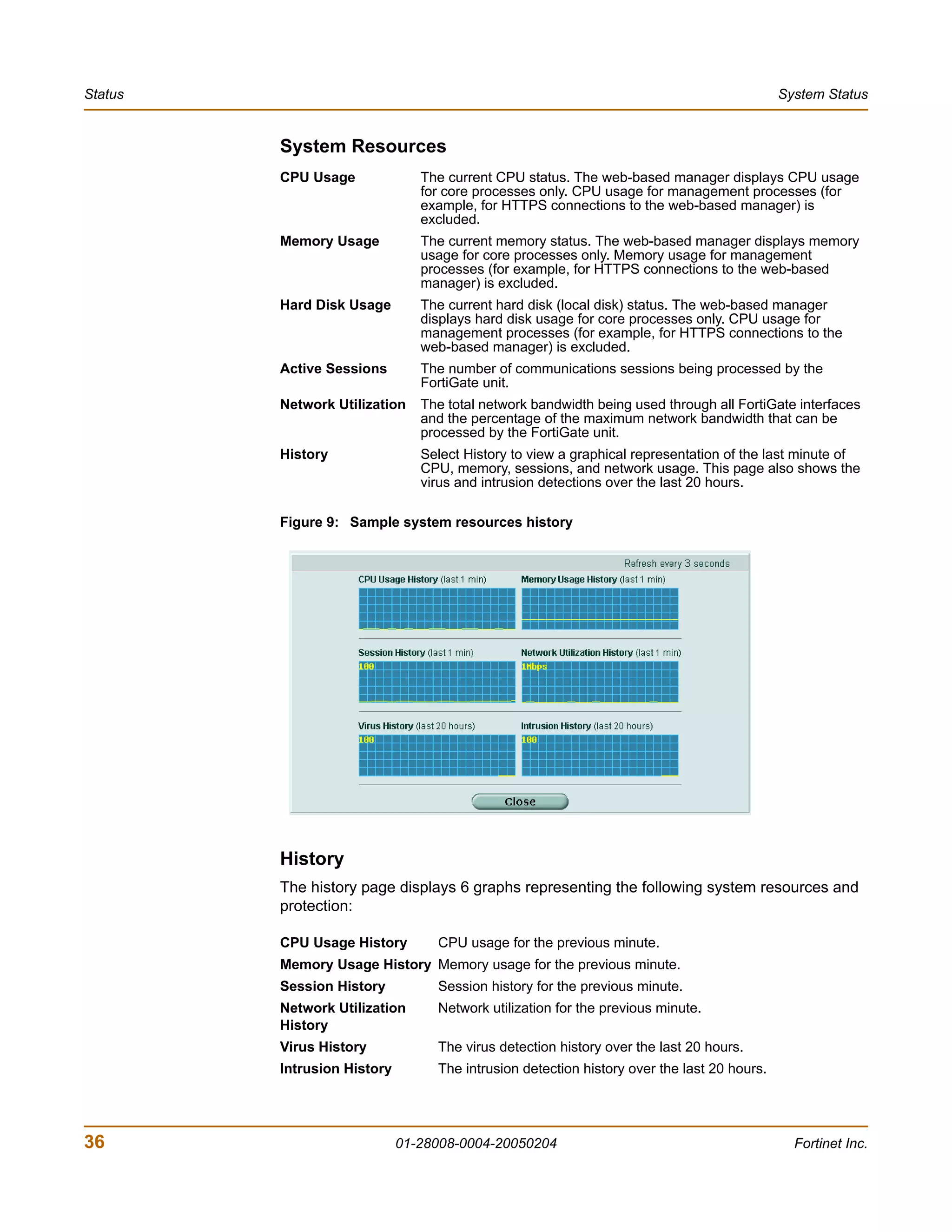
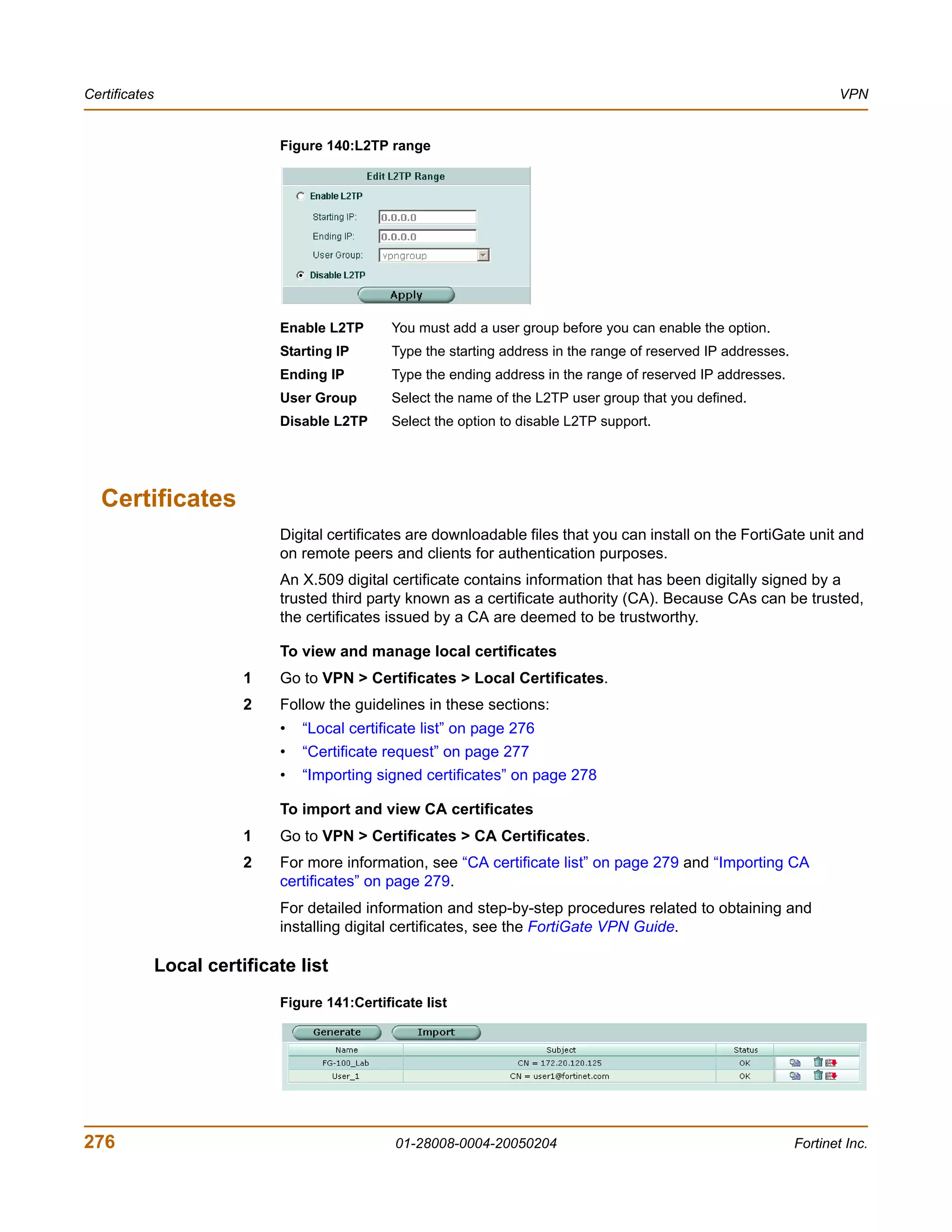
![Configuring IPS logging and alert email IPS
Configuring IPS logging and alert email
Whenever the IPS detects or prevents an attack, it generates an attack message. You
can configure the FortiGate unit to add the message to the attack log and to send an
alert email to administrators. You can configure how often the FortiGate unit sends
alert email. You can also reduce the number of log messages and alerts by disabling
signatures for attacks that your system is not vulnerable to (for example, web attacks
when you are not running a web server). For more information on FortiGate logging
and alert email, see “Log & Report” on page 355.
Default fail open setting
If for any reason the IPS should cease to function, it will fail open by default. This
means that crucial network traffic will not be blocked and the Firewall will continue to
operate while the problem is resolved.
You can change the default fail open setting using the CLI:
config sys global
set ips-open [enable | disable]
end
Enable ips_open to cause the IPS to fail open and disable ips_open to cause the
IPS to fail closed.
302 01-28008-0004-20050204 Fortinet Inc.](https://image.slidesharecdn.com/01-28008-0004-20050204fortigate-200administrationguide-121225111736-phpapp02/75/01-28008-0004-20050204-forti-gate-200_administration-guide-302-2048.jpg)

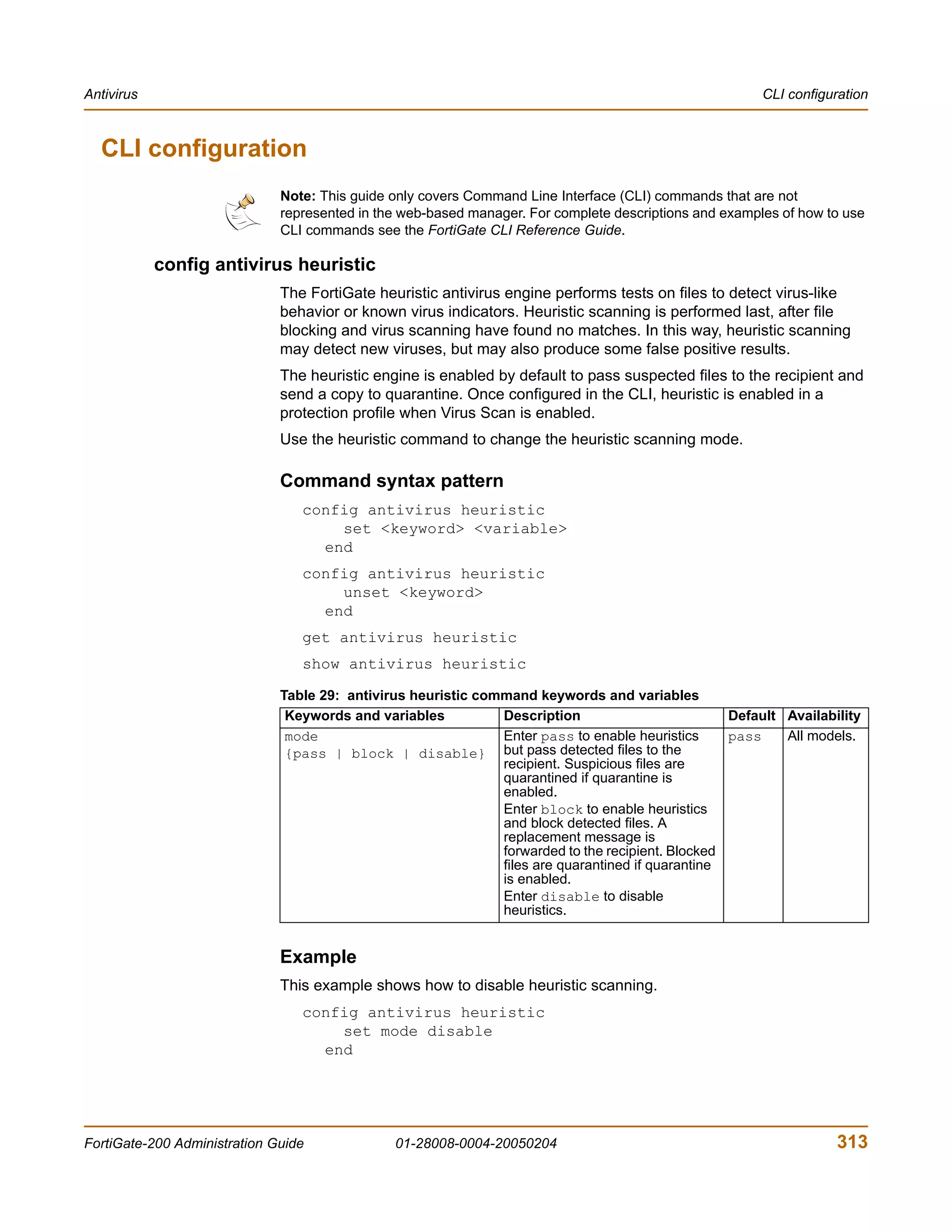
![Antivirus CLI configuration
config antivirus service http
unset <keyword>
end
get antivirus service [http]
show antivirus service [http]
antivirus service http command keywords and variables
Keywords and Description Default Availability
variables
memfilesizelimit Set the maximum file size (in megabytes) 10 (MB) All models.
<MB_integer> that can be buffered to memory for virus
scanning.
The maximum file size allowed is 10% of the
FortiGate RAM size. For example, a
FortiGate unit with 256 MB of RAM could
have a threshold range of 1 MB to 25 MB.
Note: For email scanning, the oversize
threshold refers to the final size of the email
after encoding by the email client, including
attachments. Email clients may use a variety
of encoding types and some encoding types
translate into larger file sizes than the
original attachment. The most common
encoding, base64, translates 3 bytes of
binary data into 4 bytes of base64 data. So a
file may be blocked or logged as oversized
even if the attachment is several megabytes
less than the configured oversize threshold.
port Configure antivirus scanning on a 80 All models.
<port_integer> nonstandard port number or multiple port
numbers for HTTP. You can use ports from
the range 1-65535. You can add up to 20
ports.
uncompsizelimit Set the maximum uncompressed file size 10 (MB) All models.
<MB_integer> that can be buffered to memory for virus
scanning. Enter a value in megabytes
between 1 and the total memory size. Enter
0 for no limit (not recommended).
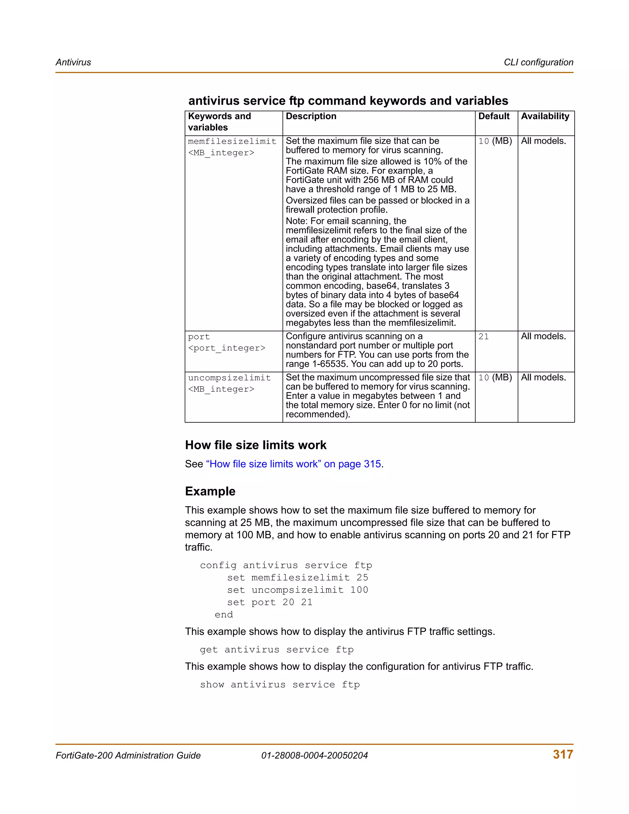
How file size limits work
The memfilesizelimit is applied first to all incoming files, compressed or
uncompressed. If the file is larger than the limit the file is passed or blocked according
to the user configuration in the firewall profile.
The uncompsizelimit applies to the uncompressed size of the file. If other files are
included within the file, the uncompressed size of each one is checked against the
uncompsizelimit value. If any one of the uncompressed files is larger than the
limit, the file is passed without scanning, but the total size of all uncompressed files
within the original file can be greater than the uncompsizelimit.
FortiGate-200 Administration Guide 01-28008-0004-20050204 315](https://image.slidesharecdn.com/01-28008-0004-20050204fortigate-200administrationguide-121225111736-phpapp02/75/01-28008-0004-20050204-forti-gate-200_administration-guide-315-2048.jpg)
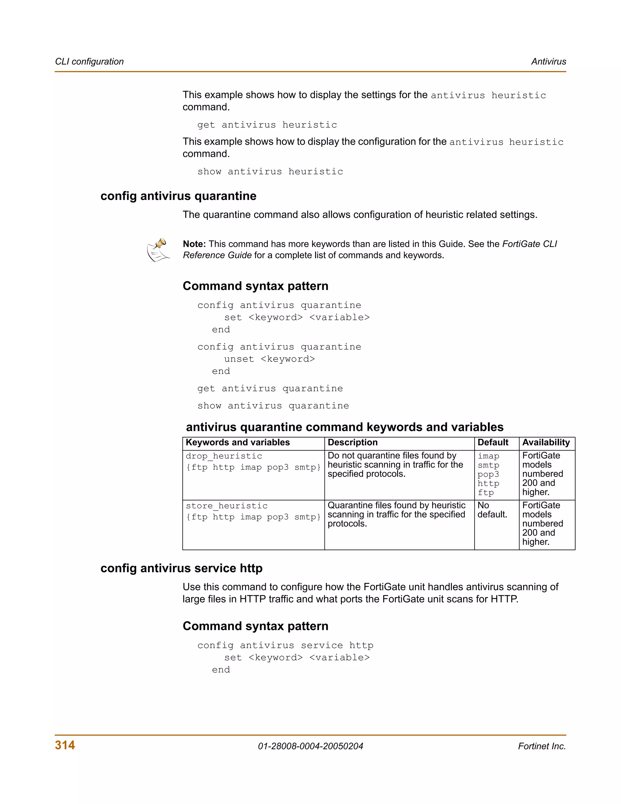
![CLI configuration Antivirus
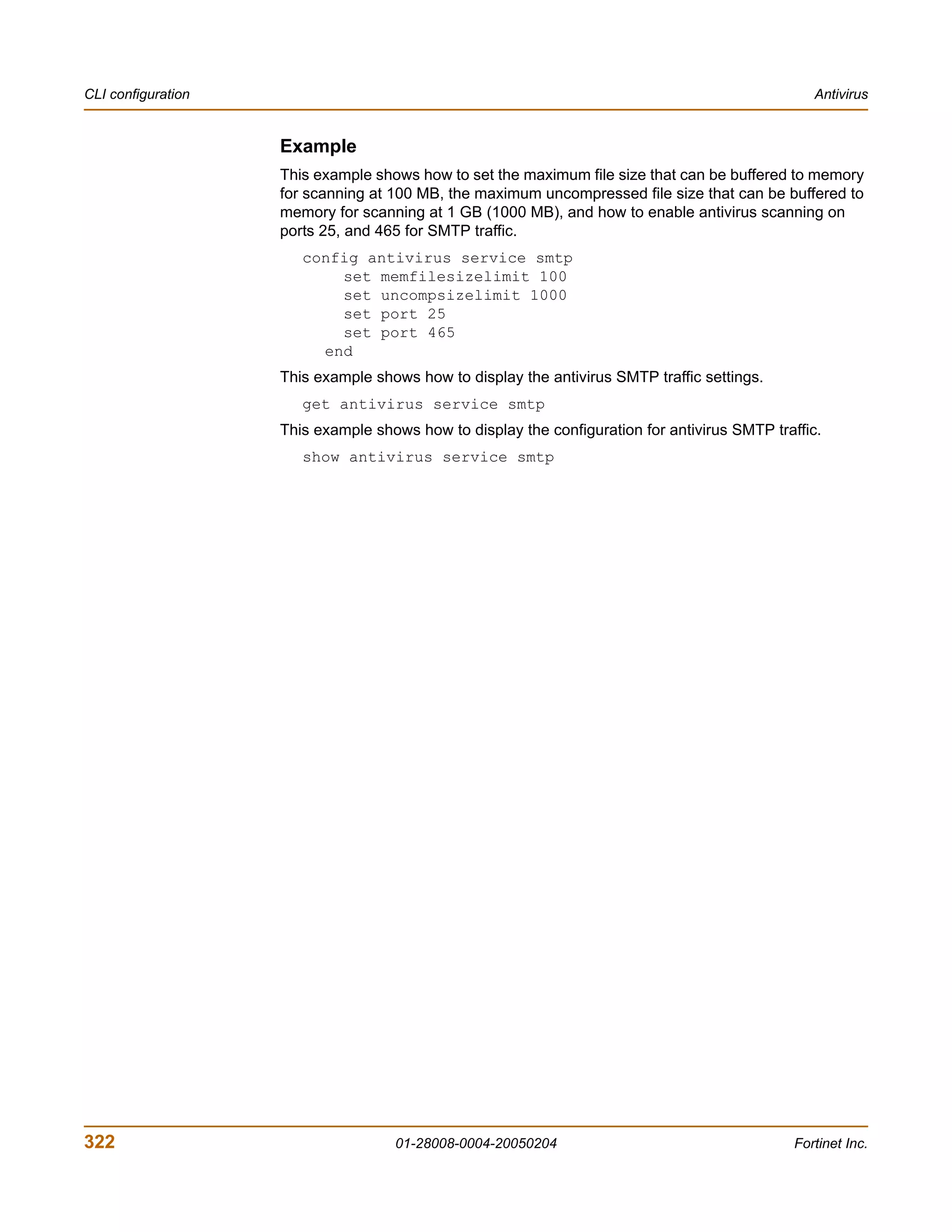
Example
This example shows how to set the maximum file size that can be buffered to memory
for scanning at 12 MB, the maximum uncompressed file size that can be buffered to
memory for scanning at 15 MB, and how to enable antivirus scanning on ports 70, 80,
and 443 for HTTP traffic.
config antivirus service http
set memfilesizelimit 12
set uncompsizelimit 15
set port 70
set port 80
set port 443
end
This example shows how to display the antivirus HTTP traffic settings.
get antivirus service http
This example shows how to display the configuration for antivirus HTTP traffic.
show antivirus service http
config antivirus service ftp
Use this command to configure how the FortiGate unit handles antivirus scanning of
large files in FTP traffic and how the FortiGate unit handles the buffering and
uploading of files to an FTP server.
Command syntax pattern
config antivirus service ftp
set <keyword> <variable>
end
config antivirus service ftp
unset <keyword>
end
get antivirus service [ftp]
show antivirus service [ftp]
316 01-28008-0004-20050204 Fortinet Inc.](https://image.slidesharecdn.com/01-28008-0004-20050204fortigate-200administrationguide-121225111736-phpapp02/75/01-28008-0004-20050204-forti-gate-200_administration-guide-316-2048.jpg)
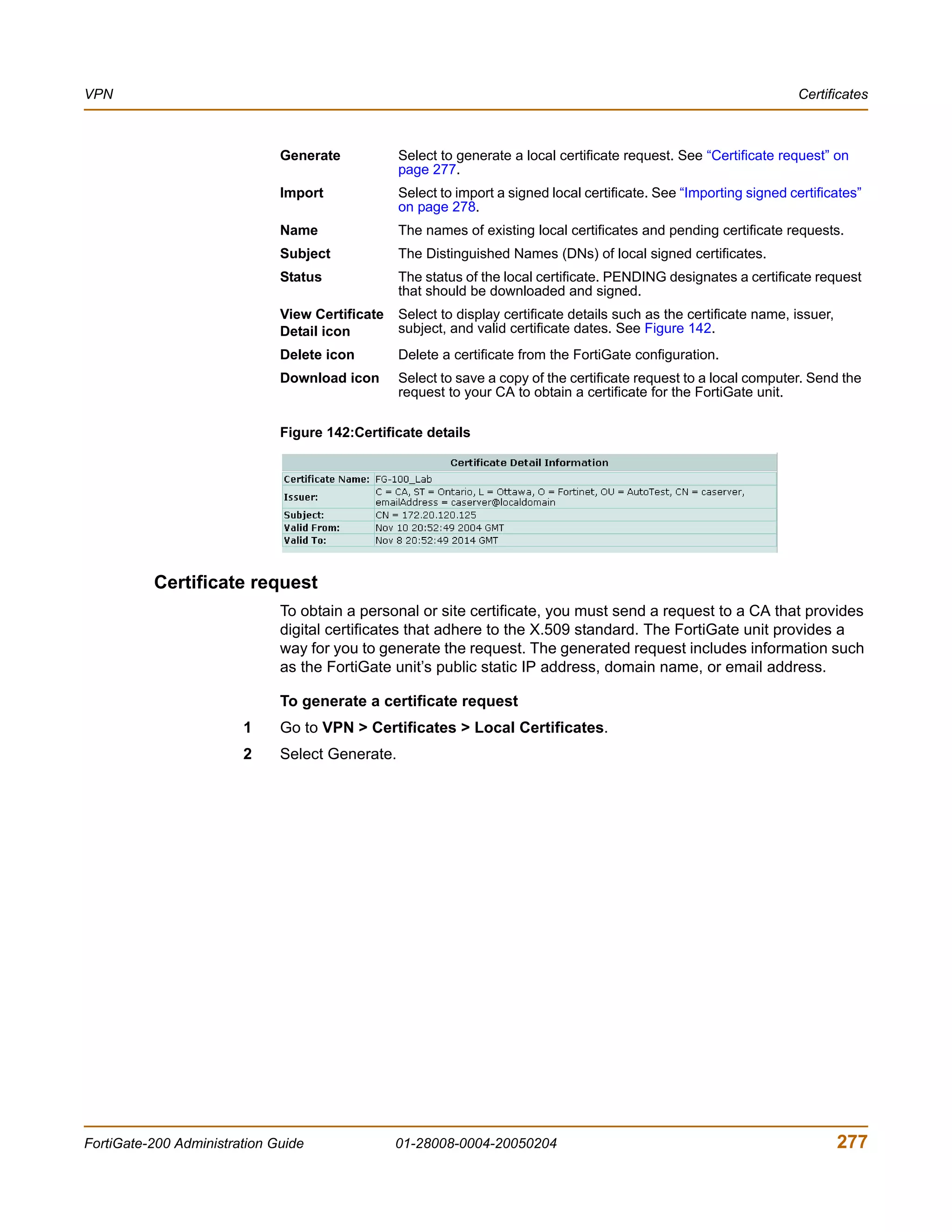
![CLI configuration Antivirus
config antivirus service pop3
Use this command to configure how the FortiGate unit handles antivirus scanning of
large files in POP3 traffic and what ports the FortiGate unit scans for POP3.
Command syntax pattern
config antivirus service pop3
set <keyword> <variable>
end
config antivirus service pop3
unset <keyword>
end
get antivirus service [pop3]
show antivirus service [pop3]
antivirus service pop3 command keywords and variables
Keywords and Description Default Availability
variables
memfilesizelimit Set the maximum file size that can be 10 (MB) All models.
<MB_integer> buffered to memory for virus scanning.
The maximum file size allowed is 10% of the
FortiGate RAM size. For example, a
FortiGate unit with 256 MB of RAM could
have a threshold range of 1 MB to 25 MB.
Note: For email scanning, the
memfilesizelimit refers to the final size of the
email after encoding by the email client,
including attachments. Email clients may
use a variety of encoding types and some
encoding types translate into larger file sizes
than the original attachment. The most
common encoding, base64, translates 3
bytes of binary data into 4 bytes of base64
data. So a file may be blocked or logged as
oversized even if the attachment is several
megabytes less than the memfilesizelimit.
port Configure antivirus scanning on a 110 All models.
<port_integer> nonstandard port number or multiple port
numbers for POP3. You can use ports from
the range 1-65535. You can add up to 20
ports.
uncompsizelimit Set the maximum uncompressed file size 10 (MB) All models.
<MB_integer> that can be buffered to memory for virus
scanning. Enter a value in megabytes
between 1 and the total memory size. Enter
0 for no limit (not recommended).
How file size limits work
See “How file size limits work” on page 315.
318 01-28008-0004-20050204 Fortinet Inc.](https://image.slidesharecdn.com/01-28008-0004-20050204fortigate-200administrationguide-121225111736-phpapp02/75/01-28008-0004-20050204-forti-gate-200_administration-guide-318-2048.jpg)
![Antivirus CLI configuration
Example
This example shows how to set the maximum file size that can be buffered to memory
for scanning at 20 MB, the maximum uncompressed file size that can be buffered to
memory for scanning at 60 MB, and how to enable antivirus scanning on ports 110,
111, and 992 for POP3 traffic.
config antivirus service pop3
set memfilesizelimit 20
set uncompsizelimit 60
set port 110
set port 111
set port 992
end
This example shows how to display the antivirus POP3 traffic settings.
get antivirus service pop3
This example shows how to display the configuration for antivirus POP3 traffic.
show antivirus service pop3
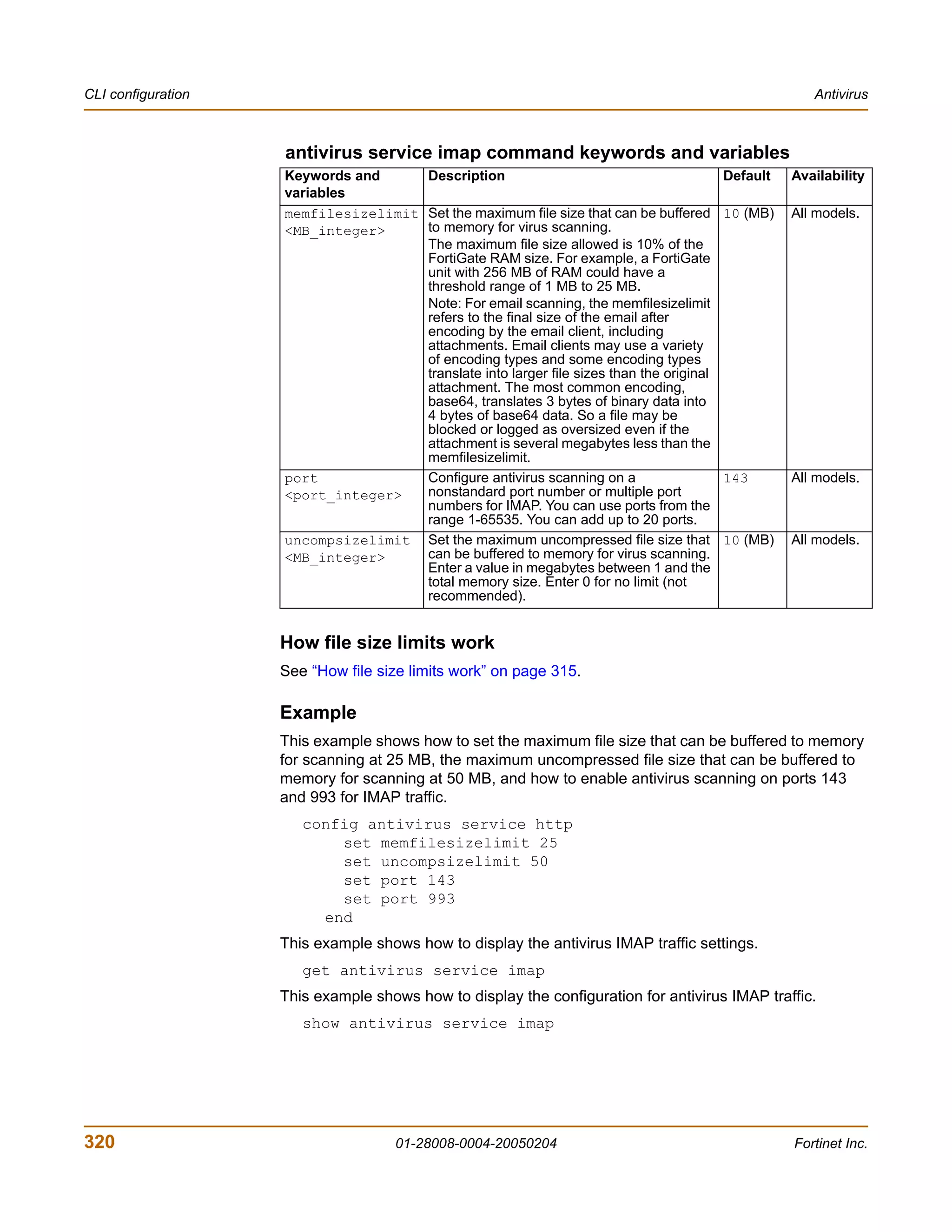
config antivirus service imap
Use this command to configure how the FortiGate unit handles antivirus scanning of
large files in IMAP traffic and what ports the FortiGate unit scans for IMAP.
Command syntax pattern
config antivirus service imap
set <keyword> <variable>
end
config antivirus service imap
unset <keyword>
end
get antivirus service [imap]
show antivirus service [imap]
FortiGate-200 Administration Guide 01-28008-0004-20050204 319](https://image.slidesharecdn.com/01-28008-0004-20050204fortigate-200administrationguide-121225111736-phpapp02/75/01-28008-0004-20050204-forti-gate-200_administration-guide-319-2048.jpg)
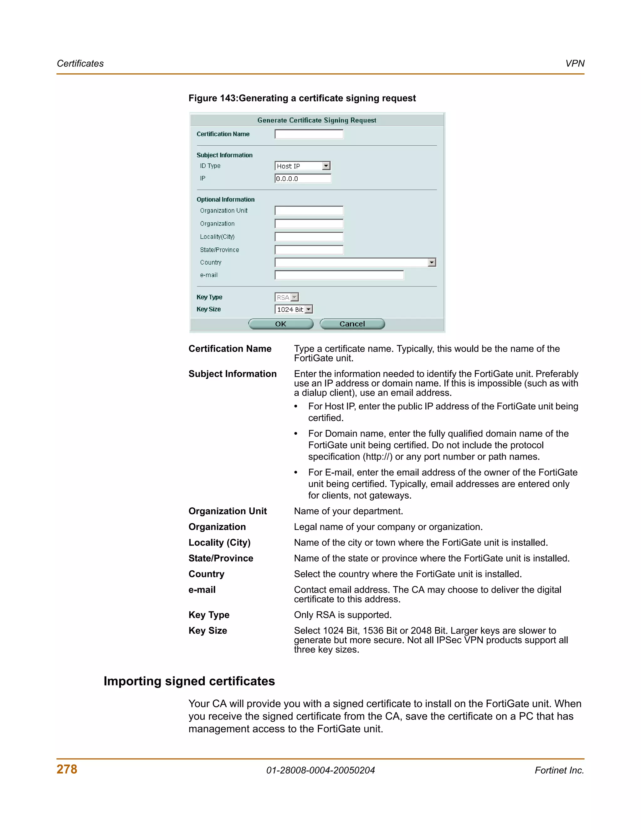
![Antivirus CLI configuration
config antivirus service smtp
Use this command to configure how the FortiGate unit handles antivirus scanning of
large files in SMTP traffic, what ports the FortiGate unit scans for SMTP, and how the
FortiGate unit handles interaction with an SMTP server for delivery of email with
infected email file attachments.
Command syntax pattern
config antivirus service smtp
set <keyword> <variable>
end
config antivirus service smtp
unset <keyword>
end
get antivirus service [smtp]
show antivirus service [smtp]
antivirus service smtp command keywords and variables
Keywords and Description Default Availability
variables
memfilesizelimit Set the maximum file size that can be 10 (MB) All models.
<MB_integer> buffered to memory for virus scanning.
The maximum file size allowed is 10% of the
FortiGate RAM size. For example, a
FortiGate unit with 256 MB of RAM could
have a threshold range of 1 MB to 25 MB.
Note: For email scanning, the
memfilesizelimit refers to the final size of the
email after encoding by the email client,
including attachments. Email clients may use
a variety of encoding types and some
encoding types translate into larger file sizes
than the original attachment. The most
common encoding, base64, translates 3
bytes of binary data into 4 bytes of base64
data. So a file may be blocked or logged as
oversized even if the attachment is several
megabytes less than the memfilesizelimit.
port Configure antivirus scanning on a 143 All models.
<port_integer> nonstandard port number or multiple port
numbers for SMTP. You can use ports from
the range 1-65535. You can add up to 20
ports.
uncompsizelimit Set the maximum uncompressed file size 10 (MB) All models.
<MB_integer> that can be buffered to memory for virus
scanning. Enter a value in megabytes
between 1 and the total memory size. Enter
0 for no limit (not recommended).
How file size limits work
See “How file size limits work” on page 315.
FortiGate-200 Administration Guide 01-28008-0004-20050204 321](https://image.slidesharecdn.com/01-28008-0004-20050204fortigate-200administrationguide-121225111736-phpapp02/75/01-28008-0004-20050204-forti-gate-200_administration-guide-321-2048.jpg)
![Using Perl regular expressions Spam filter
Regular expression vs. wildcard match pattern
In Perl regular expressions, ‘.’ character refers to any single character. It is similar to
the ‘?’ character in wildcard match pattern. As a result:
• fortinet.com not only matches fortinet.com but also matches fortinetacom,
fortinetbcom, fortinetccom and so on.
To match a special character such as '.' and ‘*’ use the escape character ‘’. For
example:
• To mach fortinet.com, the regular expression should be: fortinet.com
In Perl regular expressions, ‘*’ means match 0 or more times of the character before it,
not 0 or more times of any character. For example:
• forti*.com matches fortiiii.com but does not match fortinet.com
To match any character 0 or more times, use ‘.*’ where ‘.’ means any character and
the ‘*’ means 0 or more times. For example, the wildcard match pattern forti*.com
should therefore be fort.*.com.
Word boundary
In Perl regular expressions, the pattern does not have an implicit word boundary. For
example, the regular expression “test” not only matches the word “test” but also
matches any word that contains the “test” such as “atest”, “mytest”, “testimony”,
“atestb”. The notation “b” specifies the word boundary. To match exactly the word
“test”, the expression should be btestb.
Case sensitivity
Regular expression pattern matching is case sensitive in the Web and Spam filters. To
make a word or phrase case insensitive, use the regular expression /i For example,
/bad language/i will block all instances of “bad language” regardless of case.
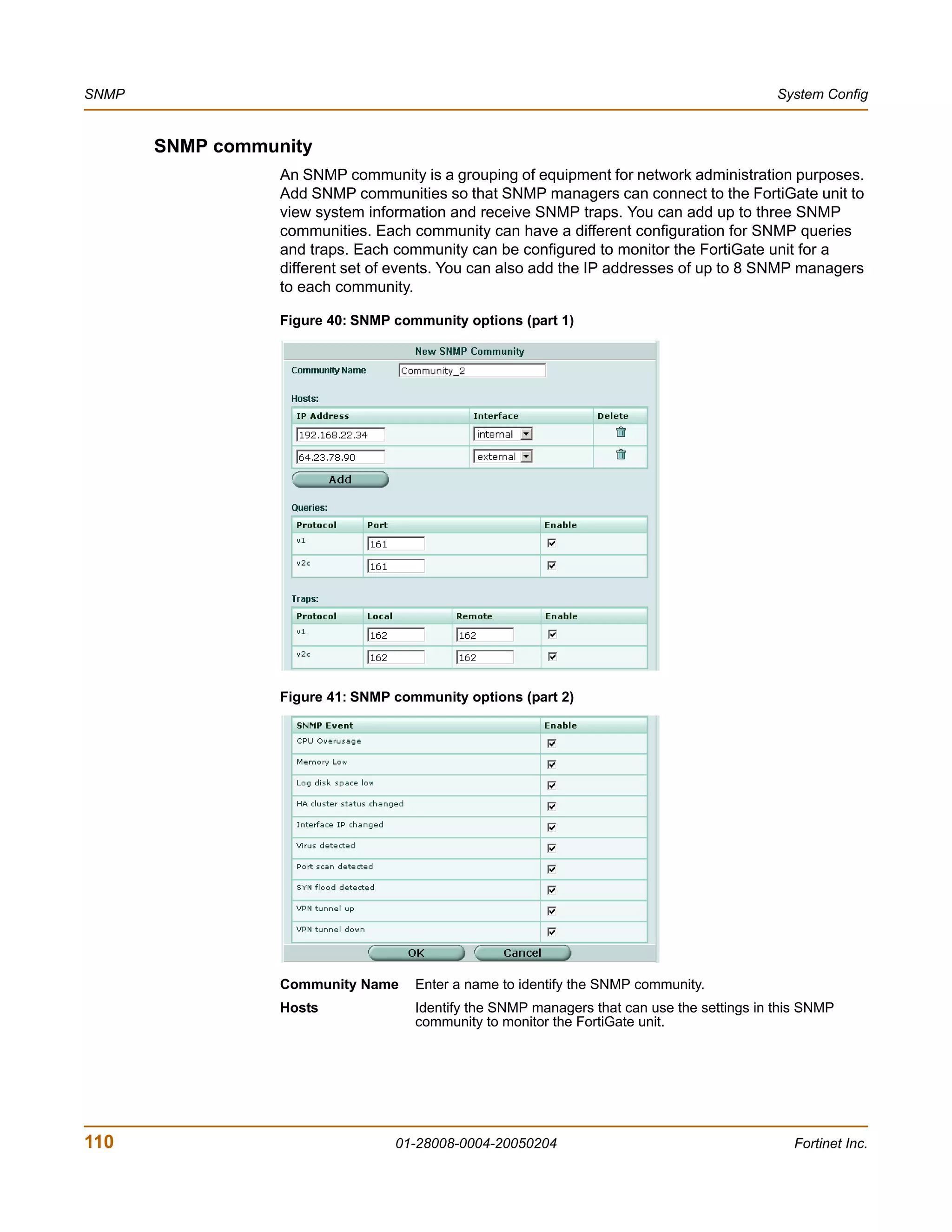
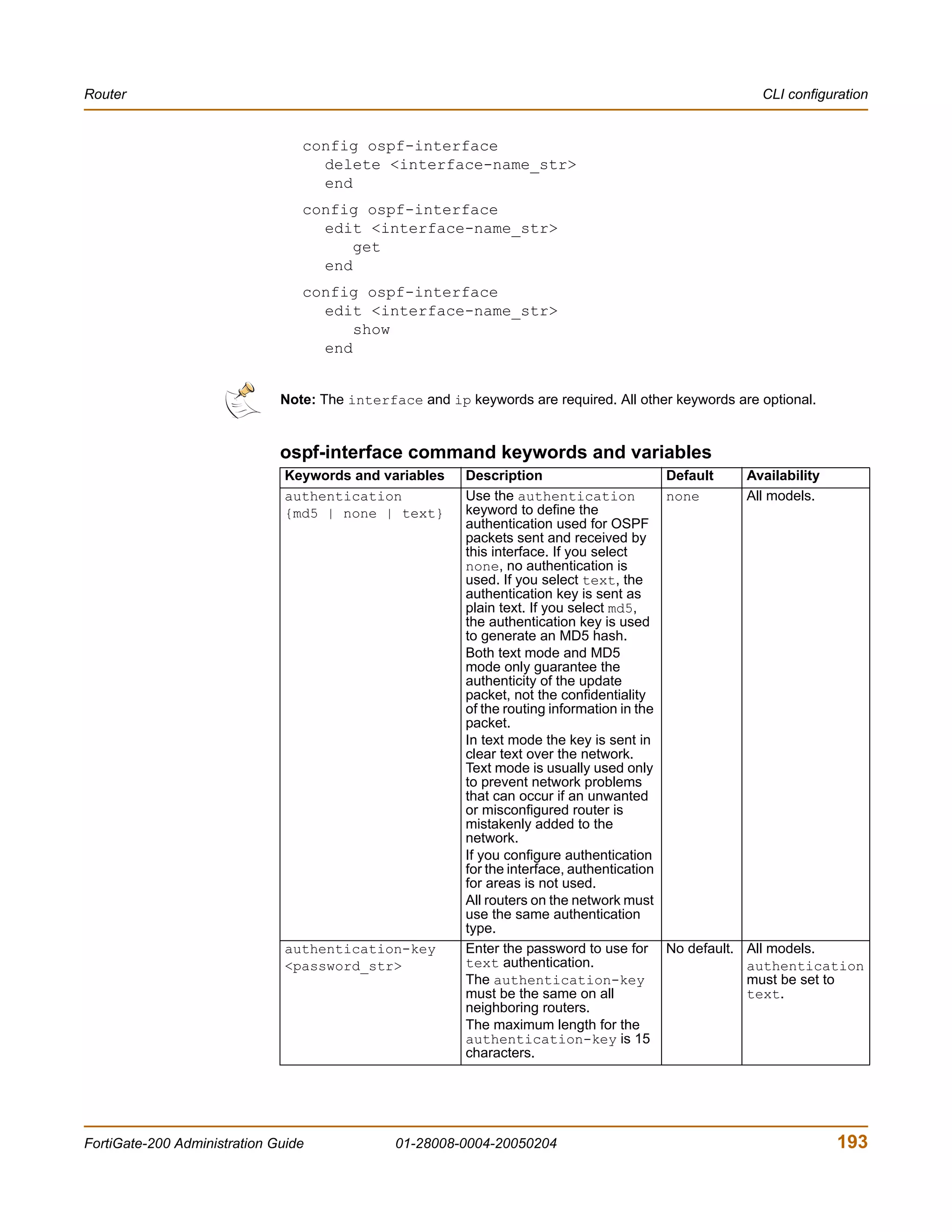
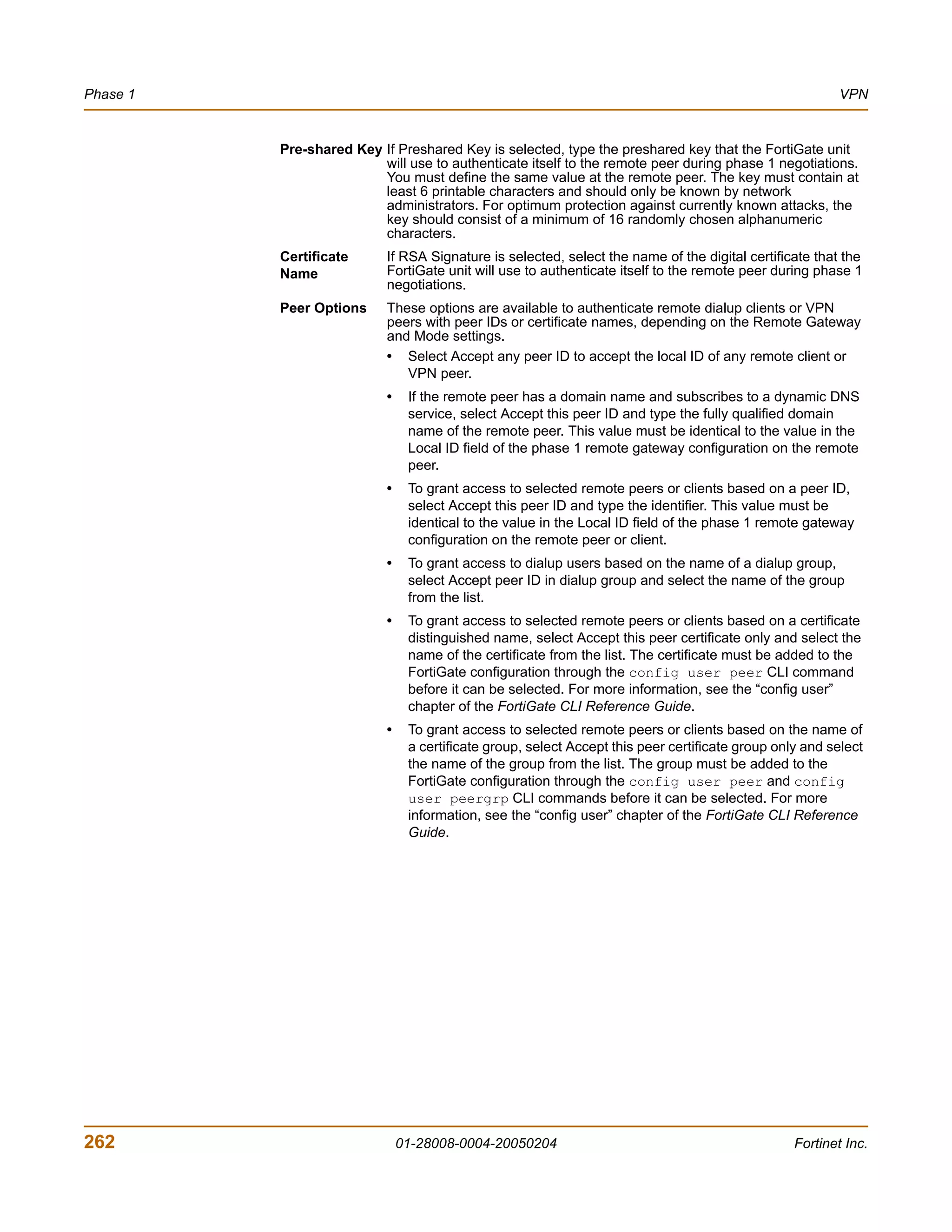
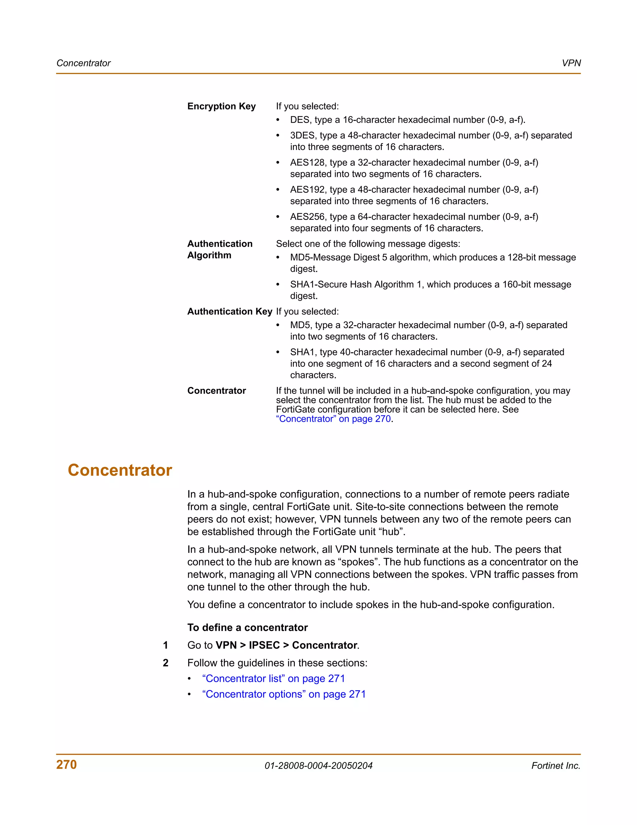
Table 32: Perl regular expression formats
Expression Matches
abc abc (that exact character sequence, but anywhere in the string)
^abc abc at the beginning of the string
abc$ abc at the end of the string
a|b either of a and b
^abc|abc$ the string abc at the beginning or at the end of the string
ab{2,4}c an a followed by two, three or four b's followed by a c
ab{2,}c an a followed by at least two b's followed by a c
ab*c an a followed by any number (zero or more) of b's followed by a c
ab+c an a followed by one or more b's followed by a c
ab?c an a followed by an optional b followed by a c; that is, either abc or ac
a.c an a followed by any single character (not newline) followed by a c
a.c a.c exactly
[abc] any one of a, b and c
352 01-28008-0004-20050204 Fortinet Inc.](https://image.slidesharecdn.com/01-28008-0004-20050204fortigate-200administrationguide-121225111736-phpapp02/75/01-28008-0004-20050204-forti-gate-200_administration-guide-352-2048.jpg)
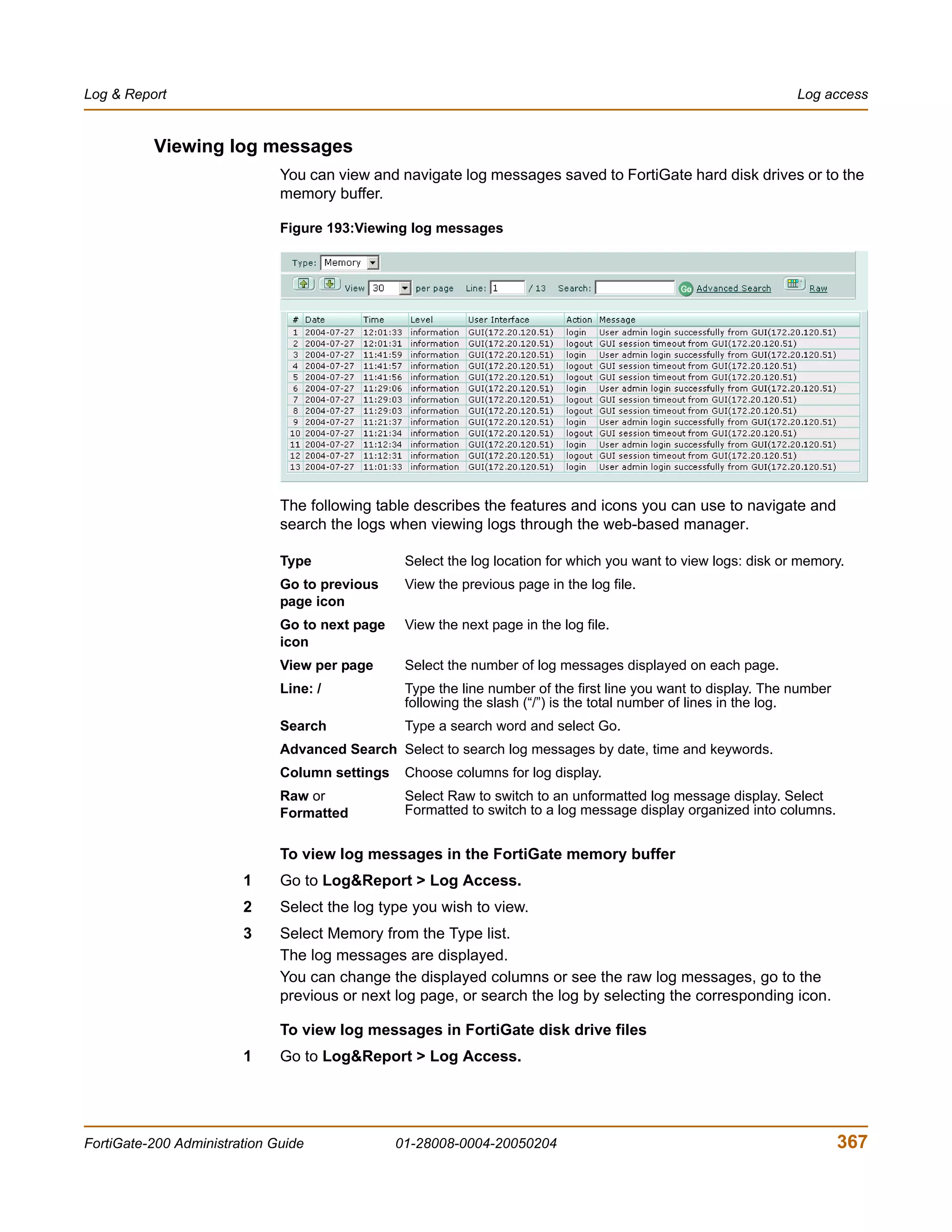
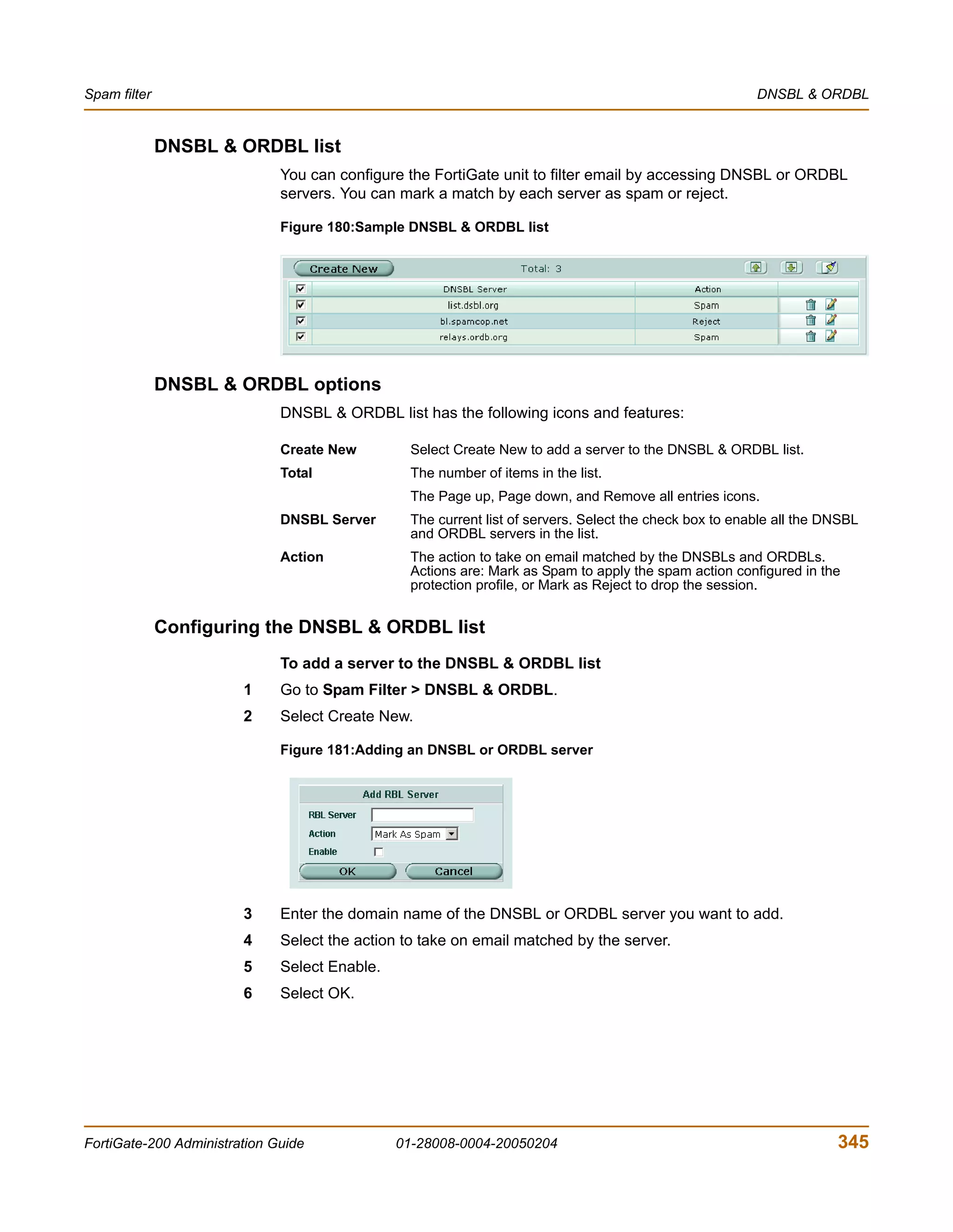
![Spam filter Using Perl regular expressions
Table 32: Perl regular expression formats
[Aa]bc either of Abc and abc
[abc]+ any (nonempty) string of a's, b's and c's (such as a, abba, acbabcacaa)
[^abc]+ any (nonempty) string which does not contain any of a, b and c (such as defg)
dd any two decimal digits, such as 42; same as d{2}
/i makes the pattern case insensitive. For example, /bad language/i blocks
any instance of bad language regardless of case.
w+ a “word”: a nonempty sequence of alphanumeric characters and low lines
(underscores), such as foo and 12bar8 and foo_1
100s*mk the strin](https://image.slidesharecdn.com/01-28008-0004-20050204fortigate-200administrationguide-121225111736-phpapp02/75/01-28008-0004-20050204-forti-gate-200_administration-guide-353-2048.jpg)