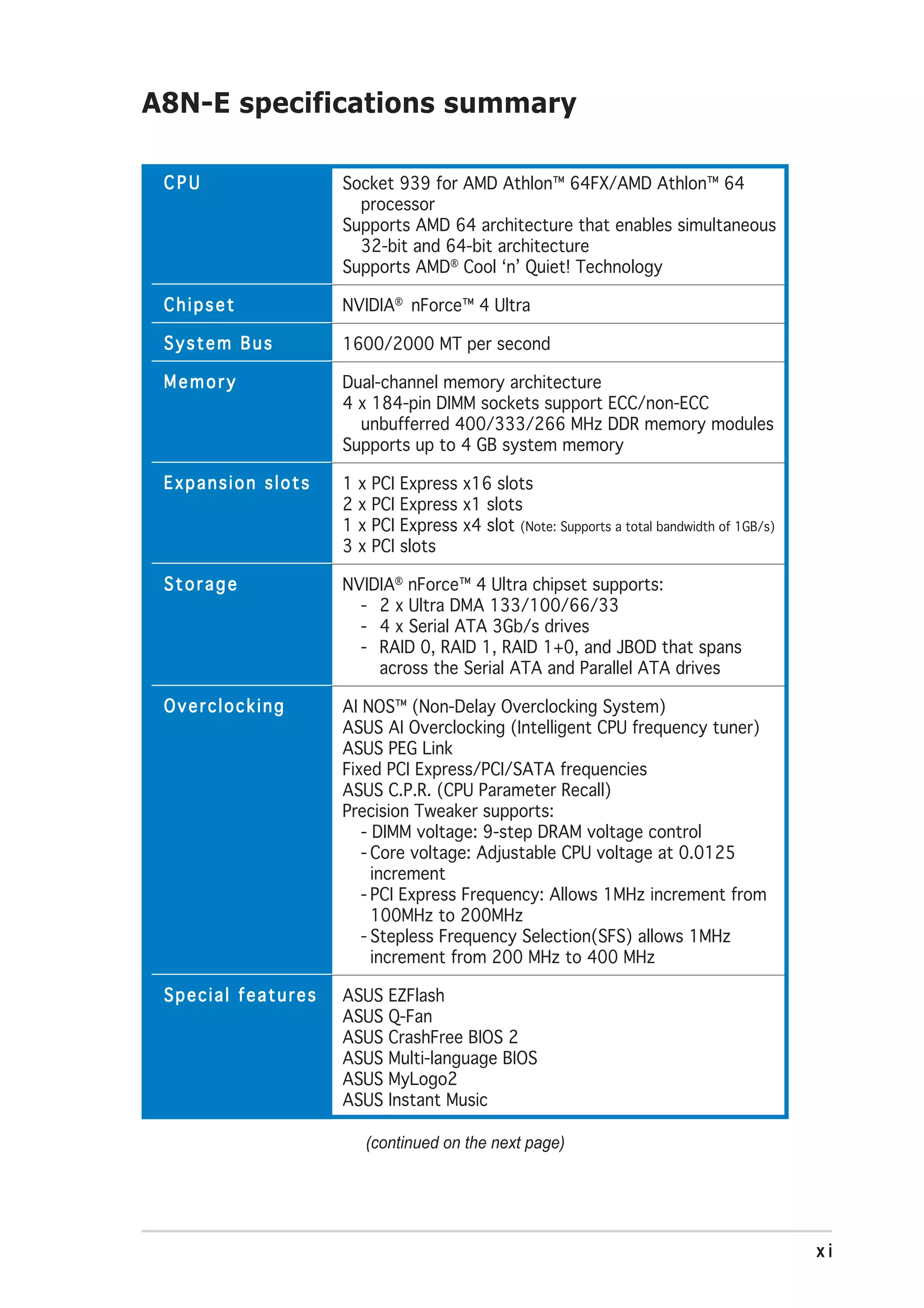
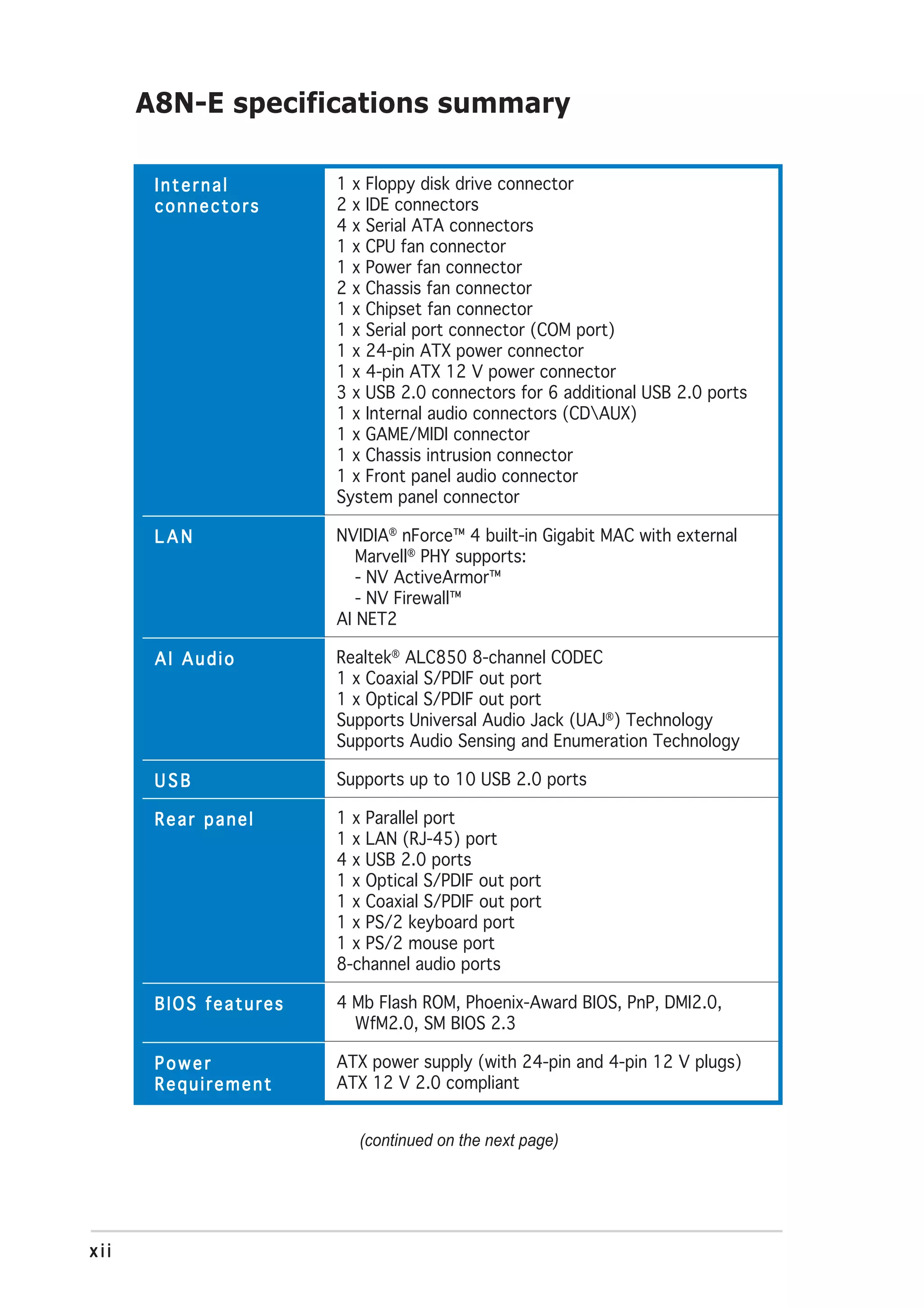
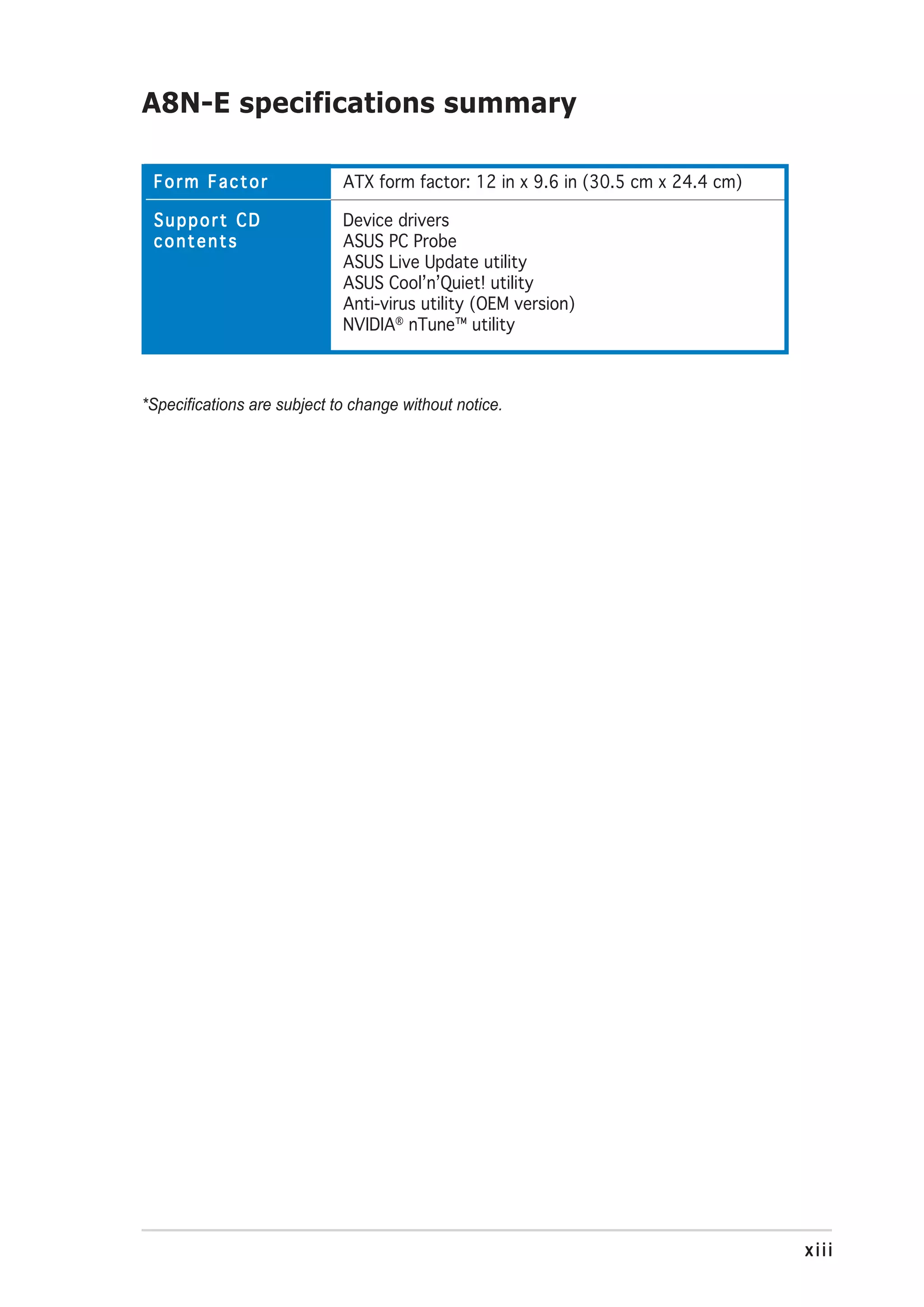
This document provides specifications for the A8N-E motherboard, including support for Socket 939 AMD Athlon 64 FX/Athlon 64 processors using the NVIDIA nForce 4 Ultra chipset. It has 4 DIMM slots supporting up to 4GB of DDR memory and dual-channel memory architecture. The motherboard utilizes 1600/2000 MT/s system bus and includes onboard audio and network features.


![2.2.1 BIOS menu screen
Menu items Menu bar Configuration fields General help
Phoenix-Award BIOS CMOS Setup Utility
Main Advanced Power Boot Exit
System Time 15 : 30 : 36 Select Menu
System Date Wed, Nov 5 2004
Language [English] Item Specific Help
Legacy Diskette A: [1.44M, 3.5 in.] Change the day, month,
year and century.
Primary IDE Master [ST321122A]
Primary IDE Slave [ASUS CDS520/A]
Secondary IDE Master [None]
Secondary IDE Slave [None]
First SATA Master [None]
Second SATA Slave [None]
Third SATA Master [None]
Fourth SATA Slave [None]
HDD SMART Monitoring [Disabled]
Installed Memory 256MB
F1:Help ↑↓ : Select Item -/+: Change Value F5: Setup Defaults
ESC: Exit →←: Select Menu Enter: Select Sub-menu F10: Save and Exit
Sub-menu items Legend bar
2.2.2 Menu bar
The menu bar on top of the screen has the following main items:
Main For changing the basic system configuration
Advanced For changing the advanced system settings
Power For changing the advanced power management (APM)
configuration
Boot For changing the system boot configuration
Exit For selecting the exit options and loading default settings
To select an item on the menu bar, press the right or left arrow key on the
keyboard until the desired item is highlighted.
• The BIOS setup screens shown in this chapter are for reference
purposes only, and may not exactly match what you see on your
screen.
• Visit the ASUS website (www.asus.com) to download the latest BIOS
information.
ASUS A8N-E 2-13](https://image.slidesharecdn.com/e1911a8n-e-130310080445-phpapp02/75/E1911-a8n-e-59-2048.jpg)
![2.2.7 Pop-up window
Select a menu item then press <Enter> to display a pop-up window with
the configuration options for that item.
Phoenix-Award BIOS CMOS Setup Utility
Main Advanced Power Boot Exit
System Time 15 : 30 : 36 Select Menu
System Date Wed, Nov 5 2004
Language [English] Item Specific Help
Legacy Diskette A: [1.44M, 3.5 in.] Specifies the capacity
Legacy Diskette A: and physical size of
Primary IDE Master [ST321122A] diskette drive A.
Primary IDE Slave Disabled ..... [ ]
[ASUS CDS520/A]
Secondary IDE Master 360K , 5.25 in.
[None] ..... [ ]
Secondary IDE Slave 1.2M , 5.25 in.
[None] ..... [ ]
First SATA Master 720K , 3.5 in.
[None] ..... [ ]
Second SATA Slave 1.44M, 3.5 in.
[None] ..... [ ]
Third SATA Master 2.88M, 3.5 in.
[None] ..... [ ]
Fourth SATA Slave [None]
HDD SMART Monitoring [Disabled]
↑↓ :Move ENTER:Accept ESC:Abort
Installed Memory 256MB
F1:Help ↑↓ : Select Item -/+: Change Value F5: Setup Defaults
ESC: Exit →←: Select Menu Enter: Select Sub-menu F10: Save and Exit
Pop-up menu
2.2.8 General help
At the top right corner of the menu screen is a brief description of the
selected item.
ASUS A8N-E 2-15](https://image.slidesharecdn.com/e1911a8n-e-130310080445-phpapp02/75/E1911-a8n-e-61-2048.jpg)
![2.3 Main menu
When you enter the BIOS Setup program, the Main menu screen appears,
giving you an overview of the basic system information.
Refer to section “2.2.1 BIOS menu screen” for information on the menu
screen items and how to navigate through them.
Phoenix-Award BIOS CMOS Setup Utility
Main Advanced Power Boot Exit
System Time 15 : 30 : 36 Select Menu
System Date Wed, Nov 5 2004
Language [English] Item Specific Help
Legacy Diskette A: [1.44M, 3.5 in.] Change the day, month,
year and century.
Primary IDE Master [ST321122A]
Primary IDE Slave [ASUS CDS520/A]
Secondary IDE Master [None]
Secondary IDE Slave [None]
First SATA Master [None]
Second SATA Slave [None]
Third SATA Master [None]
Fourth SATA Slave [None]
HDD SMART Monitoring [Disabled]
Installed Memory 256MB
F1:Help ↑↓ : Select Item -/+: Change Value F5: Setup Defaults
ESC: Exit →←: Select Menu Enter: Select Sub-menu F10: Save and Exit
2.3.1 System Time [xx:xx:xxxx]
Allows you to set the system time.
2.3.2 System Date [Day xx/xx/xxxx]
Allows you to set the system date.
2.3.3 Language [English]
Allows you to choose the BIOS language version from the options.
Configuration options: [Français] [German] [English]
2.3.4 Legacy Diskette A [1.44M, 3.5 in.]
Sets the type of floppy drive installed. Configuration options: [Disabled]
[360K, 5.25 in.] [1.2M , 5.25 in.] [720K , 3.5 in.] [1.44M, 3.5 in.]
[2.88M, 3.5 in.]
2-16 Chapter 2: BIOS setup](https://image.slidesharecdn.com/e1911a8n-e-130310080445-phpapp02/75/E1911-a8n-e-62-2048.jpg)
![2.3.5 Primary and Secondary IDE Master/Slave
While entering Setup, the BIOS automatically detects the presence of IDE
devices. There is a separate sub-menu for each IDE device. Select a device
item then press <Enter> to display the IDE device information.
Phoenix-Award BIOS CMOS Setup Utility
Main
Primary IDE Master Select Menu
PIO Mode [Auto] Item Specific Help
UDMA Mode [Auto]
Press [Enter] to
Primary IDE Master [Auto] select
Access Mode [Auto]
UDMA Mode [Auto]
Capacity 13579 MB
Cylinder 26310
Head 16
Sector 63
Transfer Mode UDMA 4
F1:Help ↑↓ : Select Item -/+: Change Value F5: Setup Defaults
ESC: Exit →←: Select Menu Enter: Select Sub-menu F10: Save and Exit
The BIOS automatically detects the values opposite the dimmed items
(Capacity, Cylinder, Head, Sector and Transfer Mode). These values are not
user-configurable. These items show N/A if no IDE device is installed in the
system.
PIO Mode
Sets the PIO mode for the IDE device.
Configuration options: [Auto] [Mode 0] [Mode 1] [Mode 2] [Mode 3]
[Mode 4]
UDMA Mode
Disables or sets the UDMA mode. Configuration options: [Disabled] [Auto]
IDE Primary Master/Slave [Auto]; IDE Secondary Master/
Slave [Auto]
Select [Auto] to automatically detect an IDE hard disk drive. If automatic
detection is successful, the BIOS automatically fills in the correct values for
the remaining fields on this sub-menu. If the hard disk was already
formatted on a previous system, the setup BIOS may detect incorrect
parameters. Select [Manual] to manually enter the IDE hard disk drive
parameters. If no drive is installed select [None].
Configuration options: [None] [Auto] [Manual]
ASUS A8N-E 2-17](https://image.slidesharecdn.com/e1911a8n-e-130310080445-phpapp02/75/E1911-a8n-e-63-2048.jpg)
![Access Mode [Auto]
The default [Auto] allows automatic detection of an IDE hard disk drive.
Select [CHS] for this item if you set the IDE Primary Master/Slave to
[Manual]. Configuration options: [CHS] [LBA] [Large] [Auto]
Before attempting to configure a hard disk drive, make sure you have
the correct configuration information supplied by the drive
manufacturer. Incorrect settings may cause the system to fail to
recognize the installed hard disk.
Capacity
Displays the auto-detected hard disk capacity. This item is not
configurable.
Cylinder
Shows the number of the hard disk cylinders. This item is not configurable.
Head
Shows the number of the hard disk read/write heads. This item is not
configurable.
Sector
Shows the number of sectors per track. This item is not configurable.
Transfer Mode
Shows the Transfer mode. This item is not configurable.
After entering the IDE hard disk drive information into BIOS, use a disk
utility, such as FDISK, to partition and format new IDE hard disk drives.
This is necessary so that you can write or read data from the hard disk.
Make sure to set the partition of the Primary IDE hard disk drives to
active.
2-18 Chapter 2: BIOS setup](https://image.slidesharecdn.com/e1911a8n-e-130310080445-phpapp02/75/E1911-a8n-e-64-2048.jpg)
![2.3.6 First, Second, Third, Fourth SATA Master
While entering Setup, the BIOS automatically detects the presence of Serial
ATA devices. There is a separate sub-menu for each SATA device. Select a
device item then press <Enter> to display the SATA device information.
Phoenix-Award BIOS CMOS Setup Utility
Main
Primary IDE Master Select Menu
Extended Drive [Auto] Item Specific Help
Access Mode [Auto]
Press [Enter] to
Capacity xxxxx MB select
Cylinder xxxxx
Head xx
Precomp xx
Landing Zone xx
Sector xx
F1:Help ↑↓ : Select Item -/+: Change Value F5: Setup Defaults
ESC: Exit →←: Select Menu Enter: Select Sub-menu F10: Save and Exit
The BIOS automatically detects the values opposite the dimmed items
(Capacity, Cylinder, Head, Precomp, Landing Zone and Sector). These
values are not user-configurable. These items show 0 if no SATA device is
installed in the system.
Extended Drive
Selects the type of fixed disk connected to the system.
Configuration options: [None] [Auto]
Access Mode
Sets the sector addressing mode. Configuration options: [Large] [Auto]
Before attempting to configure a hard disk drive, make sure you have
the correct configuration information supplied by the drive
manufacturer. Incorrect settings may cause the system to fail to
recognize the installed hard disk.
Capacity
Displays the auto-detected hard disk capacity. This item is not
configurable.
Cylinder
Shows the number of the hard disk cylinders. This item is not configurable.
ASUS A8N-E 2-19](https://image.slidesharecdn.com/e1911a8n-e-130310080445-phpapp02/75/E1911-a8n-e-65-2048.jpg)
![Head
Shows the number of the hard disk read/write heads. This item is not
configurable.
Precomp
Shows the number of precomp per track. This item is not configurable.
Landing Zone
Shows the number of landing zone per track. This item is not configurable.
Sector
Shows the number of sectors per track. This item is not configurable.
After entering the IDE hard disk drive information into BIOS, use a disk
utility, such as FDISK, to partition and format new IDE hard disk drives.
This is necessary so that you can write or read data from the hard disk.
Make sure to set the partition of the Primary IDE hard disk drives to
active.
2.3.7 HDD SMART Monitoring
Allows you to enable or disable the HDD Self-Monitoring Analysis and
Reporting Technology (SMART) feature.
Configuration options: [Disabled] [Enabled]
2.3.8 Installed Memory
Shows the size of installed memory.
2-20 Chapter 2: BIOS setup](https://image.slidesharecdn.com/e1911a8n-e-130310080445-phpapp02/75/E1911-a8n-e-66-2048.jpg)
![2.4 Advanced menu
The Advanced menu items allow you to change the settings for the CPU
and other system devices.
Take caution when changing the settings of the Advanced menu items.
Incorrect field values can cause the system to malfunction.
Phoenix-Award BIOS CMOS Setup Utility
Main Advanced Power Boot Exit
CPU Configuration Select Menu
PCIPnP
Onboard Device Configuration Item Specific Help
JumperFree Configuration
LAN Cable Status Press Enter to Set
PEG Link Mode
Instant Music
F1:Help ↑↓ : Select Item -/+: Change Value F5: Setup Defaults
ESC: Exit →←: Select Menu Enter: Select Sub-menu F10: Save and Exit
2.4.1 CPU Configuration
Phoenix-Award BIOS CMOS Setup Utility
Advanced
CPU Configuration Select Menu
CPU Type AMD Athlon(tm) 64 FX-55 Processor Item Specific Help
CPU Speed 3400MHz
Cache RAM 512K DRAM timing and
DRAM Configuration control
Hyper Transport Frequency [Auto]
AMD K8 Cool’n’Quiet control [Auto]
DRAM Configuration
The items in this sub-menu show the DRAM-related information
auto-detected by the BIOS.
Phoenix-Award BIOS CMOS Setup Utility
Advanced
DRAM Configuration Select Menu
Max Memclock (MHz) [Auto] Item Specific Help
1T/2T Memory Timing [Auto]
CAS# latency (Tcl) [Auto] Place an artificial
RAS# to CAS# delay (Trcd) [Auto] memory clock limit on
Min RAS# active time (Tras) [Auto]
Row precharge Time (Trp) [Auto] the system. Memory is
Master ECC Enabled [Disabled] prevented from
running faster than
this frequency.
ASUS A8N-E 2-21](https://image.slidesharecdn.com/e1911a8n-e-130310080445-phpapp02/75/E1911-a8n-e-67-2048.jpg)
![Max Memclock (MHz) [Auto]
Sets the maximum operating memory clock.
Configuration options: [Auto] [DDR200] [DDR266] [DDR333]
[DDR400] [DDR400] [DDR433] [DDR466] [DDR500] [DDR533]
[DDR550] [DDR600]
1T/2T Memory Timing [Auto]
Sets the memory timing. Configuration options: [Auto] [1T] [2T]
CAS# latency (Tcl) [Auto]
Sets the CAS# latency.
Configuration options: [Auto] [2.0] [2.5] [3.0]
RAS# to CAS# delay (Trcd) [Auto]
Sets the RAS# to CAS# delay to Rd/Wr command on the same bank.
Configuration options: [Auto] [2] [3] [4] [5] [6] [7]
Min RAS# active time (Tras) [Auto]
Sets the minimum RAS# active time.
Configuration options: [Auto] [5] [6] [7] [8] [9] [10] [11] [12] [13]
[14] [15]
Row precharge Time (Trp) [Auto]
Sets the Row precharge time. Precharge to Active or Auto-Refresh of
the same bank. Configuration options: [Auto] [2] [3] [4] [5] [6]
Master ECC Enable [Disabled]
Enables or disables the master ECC function.
Configuration options: [Disabled] [Enabled]
Hyper Transport Frequency [Auto]
Sets the Hyper Transport frequency.
Configuration options: [Auto] [1x] [2x] [3x] [4x] [5x] [Auto]
AMD K8 Cool’n’Quiet control [Auto]
Enables or disables the AMD Cool ‘n’ Quiet! technology.
Configuration options: [Disabled] [Enabled]
2-22 Chapter 2: BIOS setup](https://image.slidesharecdn.com/e1911a8n-e-130310080445-phpapp02/75/E1911-a8n-e-68-2048.jpg)
![2.4.2 PCIPnP
Phoenix-Award BIOS CMOS Setup Utility
Advanced
Frequency/Voltage control Select Menu
Plug & Play O/S [No] Item Specific Help
Init Display First [PCI Slot]
Resources Controlled By [Auto]
x IRQ Resources
PCI/VGA Palette Snoop [Disabled]
Plug & Play O/S [No]
When set to [No], the BIOS configures all the devices in the system. When
set to [Yes] and if you install a Plug and Play operating system, the
operating system configures the Plug and Play devices not required for
boot. Configuration options: [No] [Yes]
Resources Controlled By [Auto]
When set to [Auto], the BIOS automatically configures all the boot and
Plug and Play compatible devices. Set to [Manual] if you want to assign the
IRQ DMA and memory base address fields.
Configuration options: [Auto] [Manual]
When the item Resources Controlled By is set to [Auto], the item IRQ
Resources is grayed out and not user-configurable. Refer to the section
“IRQ Resources” for information on how to enable this item.
IRQ Resources
This sub-menu is activated only when the R e s o u r c e s C o n t r o l l e d B y
item is set to Manual.
Phoenix-Award BIOS CMOS Setup Utility
Advanced
IRQ Resources Select Menu
IRQ-3 assigned to [PCI Device] Item Specific Help
IRQ-4 assigned to [PCI Device]
IRQ-5 assigned to [PCI Device] Legacy ISA for devices
IRQ-7 assigned to [PCI Device] compliant with the
IRQ-9 assigned to [PCI Device]
IRQ-10 assigned to [PCI Device] original PC AT bus
IRQ-11 assigned to [PCI Device] specification, PCI/ISA
IRQ-12 assigned to [PCI Device] PnP for devices
IRQ-14 assigned to [PCI Device] compliant with the
IRQ-15 assigned to [PCI Device]
IRQ-xx assigned to
When set to [PCI Device], the specific IRQ is free for use of PCI/PnP
devices. When set to [Reserved], the IRQ is reserved for legacy ISA
devices. Configuration options: [PCI Device] [Reserved]
ASUS A8N-E 2-23](https://image.slidesharecdn.com/e1911a8n-e-130310080445-phpapp02/75/E1911-a8n-e-69-2048.jpg)
![PCI/VGA Palette Snoop [Disabled]
When set to [Enabled], the pallete snooping feature informs the PCI
devices that an ISA graphics device is installed in the system so that the
latter can function correctly. Configuration options: [Disabled] [Enabled]
2.4.3 Onboard Devices Configuration
Phoenix-Award BIOS CMOS Setup Utility
Advanced
Onboard Device Configuration Select Menu
IDE Function Setup Item Specific Help
NVRAID Configuration
USB Configuration
Onboard NV LAN [Enabled]
Onboard LAN Boot ROM [Disabled]
AC97 Audio [Enabled]
Serial Port1 Address [3F8/IRQ4]
Parallel Port Address [378/IRQ7]
Parallel Port Mode [ECP+EPP]
ECP MOde Use DMA [3]
Game Port Address [201]
Midi Port Address [Disabled]
x Midi Port IRQ 10
F1:Help ↑↓ : Select Item -/+: Change Value F5: Setup Defaults
ESC: Exit →←: Select Menu Enter: Select Sub-menu F10: Save and Exit
IDE Function Setup
This sub-menu contains IDE function-related items. Select an item then
press <Enter> to edit.
Phoenix-Award BIOS CMOS Setup Utility
Advanced
Onboard Device Configuration Select Menu
OnChip IDE Channel0 [Enabled] Item Specific Help
OnChip IDE Channel1 [Enabled]
IDE DMA transfer access [Enabled]
Serial Port 1, 2 [Enabled]
SATA DMA transfer [Enabled]
Serial Port 3, 4 [Enabled]
SATA2 DMA transfer [Enabled]
IDE Prefetch Mode [Enabled]
OnChip IDE Channel0 [Enabled]
Allows you to enable or disable the onchip IDE channel 0 controller .
Configuration options: [Disabled] [Enabled]
OnChip IDE Channel1 [Enabled]
Allows you to enable or disable the onchip IDE channel 1 controller .
Configuration options: [Disabled] [Enabled]
2-24 Chapter 2: BIOS setup](https://image.slidesharecdn.com/e1911a8n-e-130310080445-phpapp02/75/E1911-a8n-e-70-2048.jpg)
![IDE DMA transfer access [Enabled]
Allows you to enable or disable the IDE DMA transfer access.
Configuration options: [Disabled] [Enabled]
Serial Port 1, 2 [Enabled]
Allows you to enable or disable the SATA 1 and 2 ports.
Configuration options: [Disabled] [Enabled]
SATA DMA access [Enabled]
Allows you to enable or disable the SATA DMA transfer access.
Configuration options: [Disabled] [Enabled]
Serial Port 3, 4 [Enabled]
Allows you to enable or disable the SATA 3 and 4 ports.
Configuration options: [Disabled] [Enabled]
SATA2 DMA transfer [Enabled]
Allows you to enable or disable the SATA2 DMA transfer access.
Configuration options: [Disabled] [Enabled]
IDE Prefetch Mode [Enabled]
Allows you to enable or disable the IDE prefetch mode.
Configuration options: [Disabled] [Enabled]
NVRAID Configuration
This sub-menu contains NVRAID function-related items. Select an item then
press <Enter> to edit.
Phoenix-Award BIOS CMOS Setup Utility
Advanced
NVRAID Configuration Select Menu
RAID Enabled [Disabled] Item Specific Help
x IDE Primary Master RAID Disabled
x IDE Primary Slave RAID Disabled
x IDE Secondary Master RAID Disabled
x IDE Secondary Slave RAID Disabled
x First SATA Master RAID Disabled
x Second SATA Master RAID Disabled
x Third SATA Master RAID Disabled
x Fourth SATA Master RAID Disabled
RAID Enabled [Disabled]
Enables or disables the onboard RAID controller. When Enabled, the
succeeding items becomes user-configurable.
Configuration options: [Enabled] [Disabled]
ASUS A8N-E 2-25](https://image.slidesharecdn.com/e1911a8n-e-130310080445-phpapp02/75/E1911-a8n-e-71-2048.jpg)
![IDE Primary, Secondary Master/Slave RAID [Disabled]
Enables or disables the RAID function of the primary or secondary master
or slave IDE. Configuration options: [Enabled] [Disabled]
First, Second, Third, Fourth SATA Master RAID [Disabled]
Enables or disables the RAID function of the first, second, third or fourth
SATA master drive. Configuration options: [Enabled] [Disabled]
USB Configuration
The items in this menu allows you to change the USB-related features.
Select an item then press <Enter> to display the configuration options.
Phoenix-Award BIOS CMOS Setup Utility
Advanced
USB Configuration Select Menu
USB Controller [Enabled] Item Specific Help
USB2.0 Controller [Enabled]
USB Legacy support [Enabled]
USB Controller [Enabled]
Allows you to enable or disable the onchip USB controller.
Configuration options: [Disabled] [Enabled]
USB 2.0 Controller [Enabled]
Allows you to enable or disable the USB 2.0 controller.
Configuration options: [Disabled] [Enabled]
USB Legacy Support [Enabled]
Allows you to enable or disable support for USB devices on legacy
operating systems (OS). Configuration options: [Disabled] [Enabled]
Onboard NV LAN [Enabled]
Enables or disables the onboard NVIDIA® Gigabit LAN controller.
Configuration options: [Enabled] [Disabled]
OnBoard LAN Boot ROM [Disabled]
Allows you to enable or disable the onboard LAN boot ROM.
Configuration options: [Disabled] [Enabled]
AC97 Audio [Enabled]
Allows you to disable or enabled the onboard AC97 audio controller.
Configuration options: [Disabled] [Enabled]
2-26 Chapter 2: BIOS setup](https://image.slidesharecdn.com/e1911a8n-e-130310080445-phpapp02/75/E1911-a8n-e-72-2048.jpg)
![Serial Port1 Address [3F8/IRQ4]
Allows you to select the Serial Port1 base address.
Configuration options: [Disabled] [3F8/IRQ4] [3E8/IRQ4] [2E8/IRQ3]
Parallel Port Address [378/IRQ7]
Allows you to select the Parallel Port base addresses.
Configuration options: [Disabled] [378/IRQ7] [278/IRQ5] [3BC/IRQ7]
Parallel Port Mode [ECP+EPP]
Allows you to select the Parallel Port mode.
Configuration options: [Normal] [Bi-directional] [EPP] [ECP]
ECP Mode Use DMA [3]
Allows selection of ECP Mode. Configuration options: [1] [3]
Game Port Address [201]
Allows you to select the Game Port address or to disable the port.
Configuration options: [Disabled] [201] [209]
Midi Port Address [Disabled]
Allows you to select the Game Port address or to disable the port.
Configuration options: [Disabled] [330] [300]
Midi Port IRQ [10]
Allows you to set the Midi port IRQ address. Configuration options: [5] [10]
ASUS A8N-E 2-27](https://image.slidesharecdn.com/e1911a8n-e-130310080445-phpapp02/75/E1911-a8n-e-73-2048.jpg)
![2.4.4 JumperFree Configuration
Phoenix-Award BIOS CMOS Setup Utility
Advanced
JumperFree Configuration Select Menu
Overclock Profile [Auto] Item Specific Help
x Overclock Options Disable
x N.O.S. Option Disable
x CPU Frequency 200.00
x PCI Express Clock 100Mhz
x DDR Voltage Auto
x CPU Multiplier Auto
x CPU Voltage Auto
Overclock Profile [Auto]
Allows selection of CPU overclocking options to achieve desired CPU
internal frequency. Select either one of the preset overclocking
configuration options:
Manual Allows you to individually set overclocking
parameters.
Auto Loads the optimal settings for the system.
Standard Loads the standard settings for the system.
AI Overclock Loads overclocking profiles with optimal
parameters for stability when overclocking.
AI N.O.S. The ASUS AI Non-delay Overclocking System
feature intelligently determines the system
load and automatically boost the performance
for the most demanding tasks.
The following items are user-configurable only when the Overclock
Profile item is set to [Manual].
CPU Frequency [XXX] (value is auto-detected)
Indicates the frequency sent by the clock generator to the system bus and
PCI bus. The bus frequency (external frequency) multiplied by the bus
multiple equals the CPU speed. The value of this item is auto-detected by
BIOS. The values range from 200 to 400. Refer to the following table for
the correct Front Side Bus and CPU External Frequency settings.
Selecting a very high CPU frequency may cause the system to become
unstable! If this happens, revert to the default setting.
2-28 Chapter 2: BIOS setup](https://image.slidesharecdn.com/e1911a8n-e-130310080445-phpapp02/75/E1911-a8n-e-74-2048.jpg)
![PCI Express Clock [100MHz]
Allows you to set the PCI Express clock. Key-in a decimal value between
100-200 MHz. Configuration options: [100Mhz] [101Mhz~[145Mhz]
DDR Voltage [Auto]
Sets the operating DDR voltage. Configuration options: [Auto] [2.60V]
[2.65V] [2.70V] [2.75V] [2.80V] [2.85V] [2.90V] [2.95V] [3.00V]
CPU Multiplier [Auto]
Sets the operating CPU multiplier. The configuration options vary
depending on the type of CPU installed. Configuration options: [Auto] [x4]
[x4.5] [x5] [x5.5] [x6] [x6.5] [x7] [x7.5] [x7.5] [x8] [x8.5] [x9] [x9.5]
[x10] [x10.5] [x11] [x11.5] [x12] [x12.5] [x13] [x13.5] [x14] [x14.5]
[x15] [x15.5] [x16] [x16.5] [x17] [x17.5] [x18] [x18.5] [x19] [x19.5]
[x20]
CPU Voltage [Auto]
Sets the operating CPU voltage. Configuration options: [Auto]
[1.650V] [1.6375V] [1.625V] [1.6125V] [1.600V] [1.5875V]
[1.575V] [1.5625V] [1.550V] [1.5375V] [1.525V] [1.5125V]
[1.500V] [1.4875V] [1.475V] [1.4625V] [1.450V] [1.4375V]
[1.425V] [1.4125V] [1.400V] [1.3875V] [1.375V] [1.3625V]
[1.350V] [1.3375V] [1.325V] [1.3125V] [1.300V] [1.2875V]
[1.275V] [1.2625V] [1.250V] [1.2375V] [1.225V] [1.2125V]
[1.200V] [1.1875V] [1.175V] [1.1625V] [1.150V] [1.1375V]
[1.125V] [1.1125V] [1.100V] [1.0875V] [1.075V] [1.0625V]
[1.050V] [1.0375V] [1.025V] [1.0125V] [1.000V] [0.9875V]
[0.975V] [0.9625V] [0.950V] [0.9375V] [0.925V] [0.9125V]
[0.900V] [0.8875V] [0.875V] [0.8625V] [0.850V] [0.8375V]
[0.825V] [0.8125V] [0.800V]
The following item is user-configurable only when the AI Overclocking
item is set to [AI Overclock].
Overclock Options [Disable]
Allows you to set the oveclocking options.
Configuration options: [Disable] [Overclock 3%] [Overclock 5%]
[Overclock 8%] [Overclock 10%]
ASUS A8N-E 2-29](https://image.slidesharecdn.com/e1911a8n-e-130310080445-phpapp02/75/E1911-a8n-e-75-2048.jpg)
![The following item is user-configurable only when the AI Overclocking
item is set to [AI N.O.S.].
N.O.S. Option [Disable]
Sets the Non-Delay Overclocking System mode.
Configuration options: [Disable] [Overclock 3%] [Overclock 5%]
[Overclock 8%] [Overclock 10%]
2.4.5 LAN Cable Status
The items in this menu displays the status of the Local Area Network
(LAN) cable.
Phoenix-Award BIOS CMOS Setup Utility
Advanced
JumperFree Configuration Select Menu
POST Check LAN Cable [Disabled] Item Specific Help
Pair Status Length
1-2 Open N/A
3-6 Open N/A
4-5 Open N/A
7-8 Open N/A
POST Check LAN cable [Disabled]
Enables or disables checking of the LAN cable during the Power-On
Self-Test (POST). Configuration options: [Disabled] [Enabled]
2.4.6 PEG Link Mode
Phoenix-Award BIOS CMOS Setup Utility
Advanced
JumperFree Configuration Select Menu
PEG Link Mode [Auto] Item Specific Help
PEG Root Control [Auto]
PEG Buffer Length [Auto]
PEG Link Mode [Disabled]
Allows you to enhance the performance of your PCI Express graphics card.
Configuration options: [Auto] [Slow] [Normal] [Fast] [Faster]
PEG Root Control [Auto]
Allows you to enable or disable the PCI Express graphics root control.
Configuration options: [Auto] [Enabled] [Disabled]
2-30 Chapter 2: BIOS setup](https://image.slidesharecdn.com/e1911a8n-e-130310080445-phpapp02/75/E1911-a8n-e-76-2048.jpg)
![PEG Buffer Length [Auto]
Allows you to set the PCI Express graphics buffer length.
Configuration options: [Auto] [Long] [Short]
2.4.7 Instant Music
Phoenix-Award BIOS CMOS Setup Utility
Advanced
JumperFree Configuration Select Menu
Instant Music [Disabled] Item Specific Help
x Instant Music CD-ROM Drive Primary Master
If enabled, power up
by PS/2 keyboard
function will be
disabled.
Instant Music [Disabled]
Allows you to enable or disable the ASUS Instant Music feature.
Configuration options: [Disabled] [Enabled]
Enabling Instant Music automatically disables the PS/2 keyboard power
up feature.
Instant Music CD-ROM Drive [Primary Master]
Allows you to select the CD-ROM drive that you wish to use for the Instant
Music CD playback. Configuration options: [Primary Master] [Primary Slave]
[Secondary Master] [Secondary Slave]
ASUS A8N-E 2-31](https://image.slidesharecdn.com/e1911a8n-e-130310080445-phpapp02/75/E1911-a8n-e-77-2048.jpg)
![2.5 Power menu
The Power menu items allow you to change the settings for the Advanced
Configuration and Power Interface (ACPI) and the Advanced Power
Management (APM). Select an item then press <Enter> to display the
configuration options.
Phoenix-Award BIOS CMOS Setup Utility
Main Advanced Power Boot Exit
ACPI Suspend Type [S1&S3] Select Menu
ACPI APIC support [Enabled]
APM Configuration Item Specific Help
Hardware Monitor
Select the ACPI state
used for System
Suspend.
F1:Help ↑↓ : Select Item -/+: Change Value F5: Setup Defaults
ESC: Exit →←: Select Menu Enter: Select Sub-menu F10: Save and Exit
2.5.1 ACPI Suspend Type [S1&S3]
Allows you to select the Advanced Configuration and Power Interface
(ACPI) state to be used for system suspend.
Configuration options: [S1 (POS)] [S3(STR)] [S1&S3]
2.5.2 ACPI APIC Support [Enabled]
Allows you to enable or disable the Advanced Configuration and Power
Interface (ACPI) support in the Application-Specific Integrated Circuit
(ASIC). When set to Enabled, the ACPI APIC table pointer is included in the
RSDT pointer list. Configuration options: [Disabled] [Enabled]
2-32 Chapter 2: BIOS setup](https://image.slidesharecdn.com/e1911a8n-e-130310080445-phpapp02/75/E1911-a8n-e-78-2048.jpg)
![2.5.3 APM Configuration
Phoenix-Award BIOS CMOS Setup Utility
Power
APM Configuration Select Menu
Restore on AC Power Loss [Disabled] Item Specific Help
PWR Button < 4 secs [Instant Off]
Power On By PCI Devices [Disabled]
Power On By External Modems [Disabled] Press [ENTER] to
Power-On by RTC Alarm [Disabled] select whether or not
x Date (of Month) 0 to restart the system
x Resume Time (hh:mm:ss) 0 : 0 : 0 after AC power loss.
Power Up By PS/2 Mouse [Disabled]
Power Up By PS/2 Keyboard [Disabled]
F1:Help ↑↓ : Select Item -/+: Change Value F5: Setup Defaults
ESC: Exit →←: Select Menu Enter: Select Sub-menu F10: Save and Exit
Restore on AC Power Loss [Disabled]
Allows you to enable or disable the Restore on AC Power Loss function.
Configuration options: [Disabled] [Enabled]
PWR Button < 4 secs [Instant-Off]
Allows you to set the event after the power button is pressed for more
than 4 seconds. Configuration options: [Suspend] [Instant-Off]
Power On By PCI Devices [Disabled]
When set to [Enabled], this parameter allows you to turn on the system
through a PCI LAN or modem card. This feature requires an ATX power
supply that provides at least 1A on the +5VSB lead.
Configuration options: [Disabled] [Enabled]
Power On By External Modems [Disabled]
This allows either settings of [Enabled] or [Disabled] for powering up the
computer when the external modem receives a call while the computer is in
Soft-off mode. Configuration options: [Disabled] [Enabled]
The computer cannot receive or transmit data until the computer and
applications are fully running. Thus, connection cannot be made on the
first try. Turning an external modem off and then back on while the
computer is off causes an initialization string that turns the system
power on.
ASUS A8N-E 2-33](https://image.slidesharecdn.com/e1911a8n-e-130310080445-phpapp02/75/E1911-a8n-e-79-2048.jpg)
![Power On By RTC Alarm [Disabled]
Allows you to enable or disable RTC to generate a wake event. When this
item is set to Enabled, the items Date of Month Alarm and Time (hh:mm:ss)
Alarm items become user-configurable with set values.
Configuration options: [Disabled] [Enabled]
Day of Month Alarm [Disabled]
To set the date of alarm, highlight this item and press <Enter> to display
the Day of Month Alarm pop-up menu. Key-in a value within the specified
range then press <Enter>. Configuration options: [Min=0] [Max=31]
Time (hh:mm:ss) Alarm [Disabled]
To set the time of alarm:
1. Highlight this item and press <Enter> to display a pop-up menu for the
hour field.
2. Key-in a value (Min=0, Max=23), then press <Enter>.
3. Press <TAB> to move to the minutes field then press <Enter>.
4. Key-in a minute value (Min=0, Max=59), then press <Enter>.
5. Press <TAB> to move to the seconds field then press <Enter>.
6. Key-in a value (Min=0, Max=59), then press <Enter>.
Power Up By PS/2 Mouse [Disabled]
When set to [Enabled], this parameter allows you to use the PS/2 mouse
to turn on the system. This feature requires an ATX power supply that
provides at least 1A on the +5VSB lead.
Configuration options: [Disabled] [Enabled]
Power On By PS/2 Keyboard [Disabled]
Allows you to disable the Power On by PS/2 keyboard function or set
specific keys on the PS/2 keyboard to turn on the system. This feature
requires an ATX power supply that provides at least 1A on the +5VSB lead.
Configuration options: [Disabled] [Space Bar] [Ctrl-ESC] [Power Key]
2-34 Chapter 2: BIOS setup](https://image.slidesharecdn.com/e1911a8n-e-130310080445-phpapp02/75/E1911-a8n-e-80-2048.jpg)
![2.5.4 Hardware Monitor
The items in this sub-menu displays the hardware monitor values
automatically detected by the BIOS. It also allows you to change CPU Q-Fan
feature-related parameters. Select an item then press <Enter> to display
the configuration options.
Phoenix-Award BIOS CMOS Setup Utility
Power
Hardware Monitor Select Menu
Q-Fan Controller [Disabled] Item Specific Help
Vcore Voltage 1.50V
3.3V Voltage 3.31V
5V Voltage 4.94V Press [Enter] to
12V Voltage 11.26V enable or disable
CPU Temperature 48ºC
M/B Temperature 38ºC
CPU FAN Speed 4962 RPM
CHA1 FAN Speed 0 RPM
CHIP FAN Speed 5443 RPM
x CPU Target Temperature 72ºC
F1:Help ↑↓ : Select Item -/+: Change Value F5: Setup Defaults
ESC: Exit →←: Select Menu Enter: Select Sub-menu F10: Save and Exit
Q-Fan Controller [Disabled]
Allows you to enable or disable the Q-Fan controller.
Configuration options: [Disabled] [Enabled]
VCORE Voltage, +12V Voltage, 3.3V Voltage, 5VCC
Voltage
The onboard hardware monitor automatically detects the voltage output
through the onboard voltage regulators. These items are not
user-configurable.
CPU Temperature, M/B Temperature
The onboard hardware monitor automatically detects and displays the
motherboard and CPU temperatures. These items are not user-configurable.
CPU Fan Speed
CHA1 Fan Speed
CHIP Fan Speed
The onboard hardware monitor automatically detects and displays the
Chassis, CPU, and Chip fan speeds in rotations per minute (RPM). If the fan
is not connected to the motherboard, the field shows 0. These items are
not user-configurable.
ASUS A8N-E 2-35](https://image.slidesharecdn.com/e1911a8n-e-130310080445-phpapp02/75/E1911-a8n-e-81-2048.jpg)
![CPU Target Temperature
Allows you to set the temperature threshold before the CPU fan rotates at
full speed. Configuration options: [51ºC] [54ºC] [57ºC] [60ºC] [63ºC]
[66ºC] [69ºC] [72ºC] [75ºC] [78ºC] [81ºC]
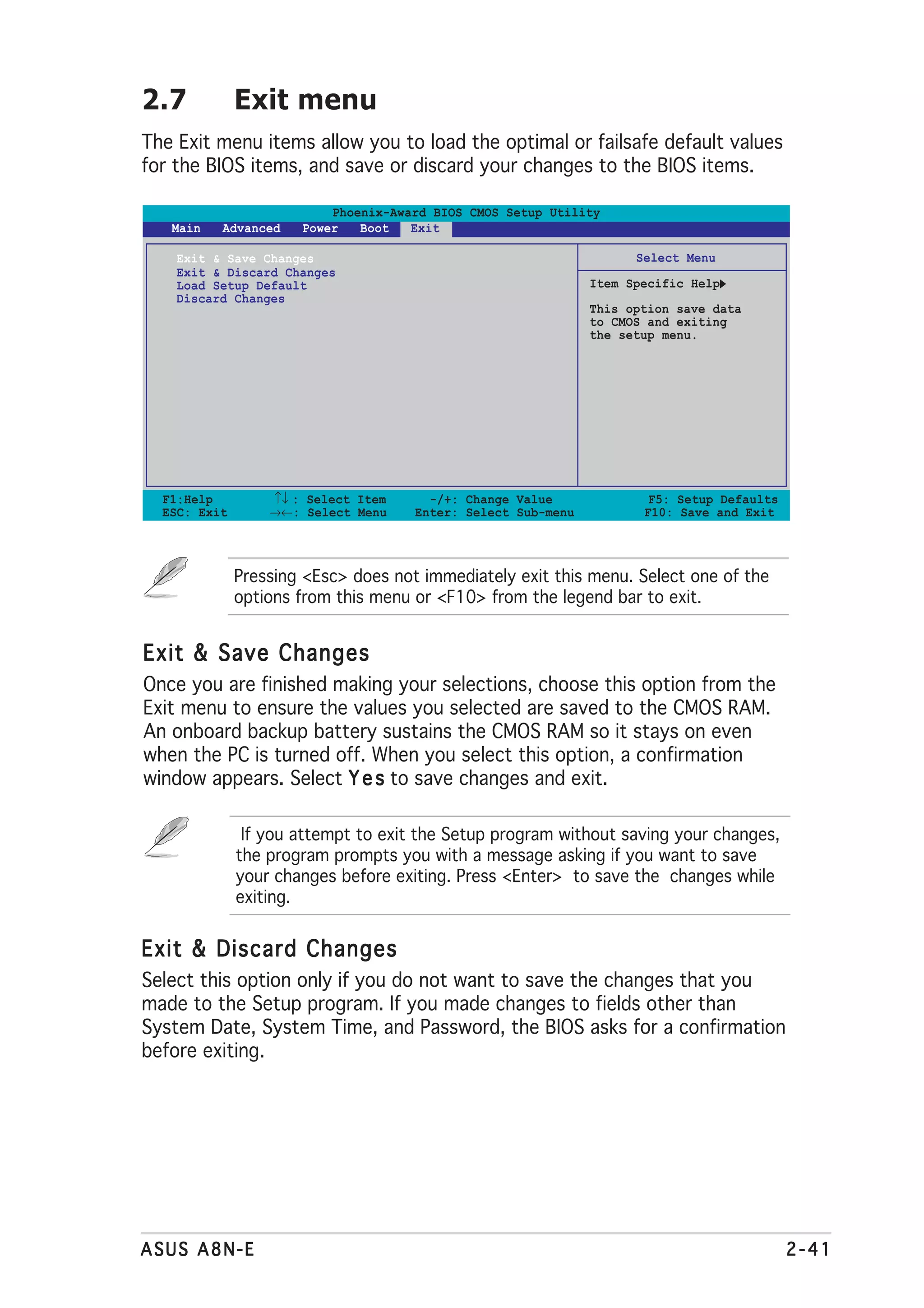
2.6 Boot menu
The Boot menu items allow you to change the system boot options. Select
an item then press <Enter> to display the sub-menu.
Phoenix-Award BIOS CMOS Setup Utility
Main Advanced Power Boot Exit
Boot Device Priority Select Menu
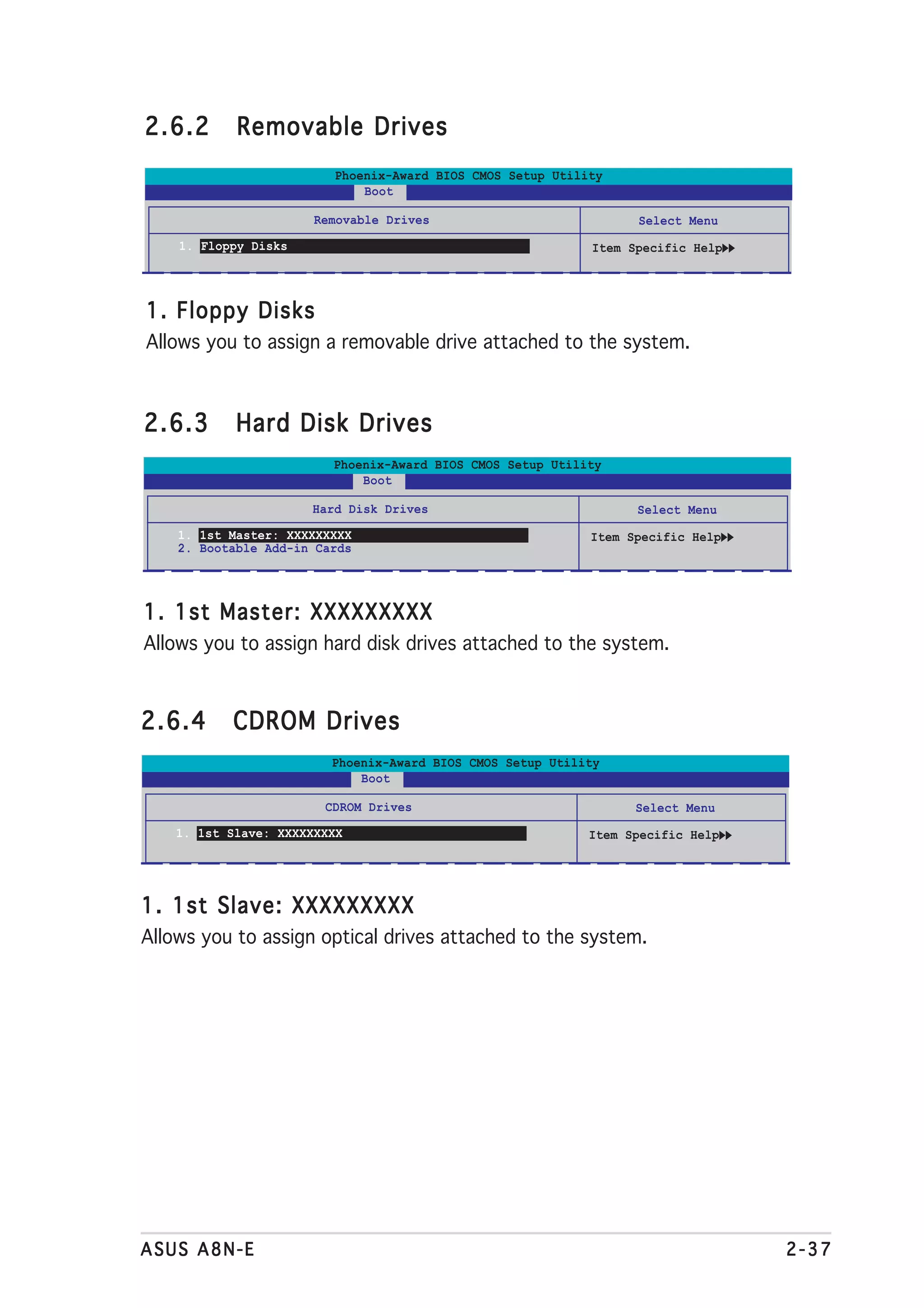
Removable Drives
Hard Disk Drives Item Specific Help
CDROM Drives
Boot Settings Configuration
Security
F1:Help ↑↓ : Select Item -/+: Change Value F5: Setup Defaults
ESC: Exit →←: Select Menu Enter: Select Sub-menu F10: Save and Exit
2.6.1 Boot Device Priority
Phoenix-Award BIOS CMOS Setup Utility
Power
Boot Device Priority Select Menu
1st Boot Device [Removable] Item Specific Help
2nd Boot Device [Hard Disk]
3rd Boot Device [CDROM]
4th Boot Device [Disabled] Select your boot
device priority
1st ~ xxth Boot Device [Removable]
These items specify the boot device priority sequence from the available
devices. The number of device items that appears on the screen depends
on the number of devices installed in the system.
Configuration options: [Removable] [Hard Disk] [CDROM] [Legacy LAN]
[Disabled]
2-36 Chapter 2: BIOS setup](https://image.slidesharecdn.com/e1911a8n-e-130310080445-phpapp02/75/E1911-a8n-e-82-2048.jpg)
![2.6.5 Boot Settings Configuration
Phoenix-Award BIOS CMOS Setup Utility
Boot
Boot Settings Configuration Select Menu
Case Open Warning [Enabled] Item Specific Help
Quick Boot [Enabled]
Boot Up Floppy Seek [Enabled]
Bootup Num-Lock [On] Press [Enter] to
Typematic Rate Setting [Disabled] enable or disable.
x Typematic Rate (Chars/Sec) 6
x Typematic Delay (Msec) 250
OS Select For DRAM > 64MB [Non-OS2]
Full Screen LOGO [Enabled]
Halt On [All Errors]
F1:Help ↑↓ : Select Item -/+: Change Value F5: Setup Defaults
ESC: Exit →←: Select Menu Enter: Select Sub-menu F10: Save and Exit
Case Open Warning [Enabled]
Enables or disables the chassis open status feature. Setting to Enabled,
clears the chassis open status. Refer to section “2.7 Internal connectors”
for setting details. Configuration options: [Disabled] [Enabled]
Quick Boot [Enabled]
Allows you to enable or disable the system quick boot feature. When
Enabled, the system skips certain tests while booting.
Configuration options: [Disabled] [Enabled]
Boot Up Floppy Seek [Enabled]
Enables or disables the chassis open status feature. Setting to Enabled,
clears the chassis open status. Configuration options: [Disabled] [Enabled]
Bootup Num-Lock [On]
Allows you to select the power-on state for the NumLock.
Configuration options: [Off] [On]
Typematic Rate Setting [Disabled]
Allows you to set the keystroke rate. Enable this item to configure the
T y p e m a t i c R a t e ( C h a r s / S e c ) and the T y p e m a t i c D e l a y ( M s e c )
).
Configuration options: [Disabled] [Enabled]
The items T y p e m a t i c R a t e ( C h a r s / S e c ) and T y p e m a t i c D e l a y
( M s e c ) becomes user-configurable only when the item Typematic Rate
Setting is enabled.
2-38 Chapter 2: BIOS setup](https://image.slidesharecdn.com/e1911a8n-e-130310080445-phpapp02/75/E1911-a8n-e-84-2048.jpg)
![Typematic Rate (Chars/Sec) [6]
Allows you to select the rate at which a character repeats when you hold a
key. Configuration options: [6] [8] [10] [12] [15] [20] [24] [30]
Typematic Delay (Msec) [250]
Allows you to set the delay before keystrokes begin to repeat.
Configuration options: [250] [500] [750] [1000]
OS Select for DRAM > 64MB [Non-OS2]
Set this item to OS2 only when you are running on an OS/2 operating
system with an installed RAM of greater than 64 KB.
Configuration options: [Non-OS2] [OS2]
Full Screen LOGO [Enabled]
Allows you to enable or disable the full screen logo display feature.
Configuration options: [Disabled] [Enabled]
• Make sure that the above item is set to [Enabled] if you want to use
the ASUS MyLogo2™ feature.
• See section “3.3.1 ASUS MyLogo2™” for details.
Halt On [All Errors]
Allows you to error report type.
Configuration options: [All Errors] [No Errors] [All, But Keyboard]
[All, But Diskette] [All, But Disk/Key]
2.6.6 Security
Phoenix-Award BIOS CMOS Setup Utility
Boot
Boot Settings Configuration Select Menu
Supervisor Password Clear Item Specific Help
User Password Clear
Password Check [Setup]
Supervisor Password
User Password
These fields allow you to set passwords:
To set a password:
1. Select an item then press <Enter>.
2. Type in a password using a combination of a maximum of eight (8)
alpha-numeric characters, then press <Enter>.
ASUS A8N-E 2-39](https://image.slidesharecdn.com/e1911a8n-e-130310080445-phpapp02/75/E1911-a8n-e-85-2048.jpg)
![3. When prompted, confirm the password by typing the exact characters
again, then press <Enter>. The password field setting is changed to
Set.
To clear the password:
1. Select the password field and press <Enter> twice. The following
message appears:
PASSWORD DISABLED !!!
Press any key to continue...
2. Press any key to continue. The password field setting is changed to
Clear.
A note about passwords
The Supervisor password is required to enter the BIOS Setup program
preventing unauthorized access. The User password is required to
boot the system preventing unauthorized use.
Forgot your password?
If you forget your password, you can clear it by erasing the CMOS Real
Time Clock (RTC) RAM. The RAM data containing the password
information is powered by the onboard button cell battery. If you need
to erase the CMOS RAM, refer to section “2.6 Jumpers” for
instructions.
Password Check
This field requires you to enter the password before entering the BIOS
setup or the system. Select [Setup] to require the password before
entering the BIOS Setup. Select [System] to require the password before
entering the system. Configuration options: [Setup] [System]
2-40 Chapter 2: BIOS setup](https://image.slidesharecdn.com/e1911a8n-e-130310080445-phpapp02/75/E1911-a8n-e-86-2048.jpg)
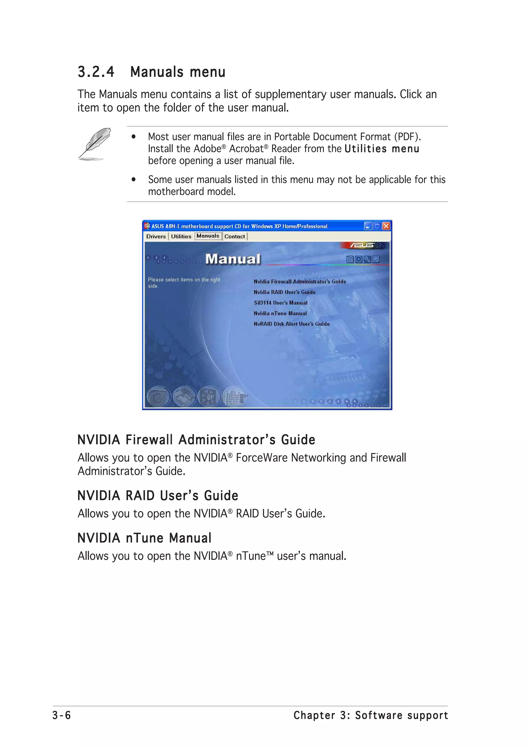
![3.3 Software information
Most of the applications in the support CD have wizards that will
conveniently guide you through the installation. View the online help or
readme file that came with the software application for more information.
3.3.1 ASUS MyLogo2™
The ASUS MyLogo2™ utility lets you customize the boot logo. The boot
logo is the image that appears on screen during the Power-On Self-Tests
(POST). The ASUS MyLogo2™ is automatically installed when you install the
A S U S U p d a t e utility from the support CD. See section “3.2.3 Utilities
menu” for details.
• Before using the ASUS MyLogo2™, use the Award BIOS Flash utility
to make a copy of your original BIOS file, or obtain the latest BIOS
version from the ASUS website. See section “2.1.2 Updating the
BIOS”.
• Make sure that the BIOS item F u l l S c r e e n L o g o is set to
[Enabled] if you wish to use ASUS MyLogo2. See section “2.6.2
Boot Settings Configuration”.
• You can create your own boot logo image in GIF, JPG, or BMP file
formats.
To launch the ASUS MyLogo2™:
1. Launch the ASUS Update utility. Refer to section “2.1.5 ASUS Update
utility” for details.
2. t.
Select O p t i o n s from the drop down menu, then click N e x t
3. Check the option L a u n c h M y L o g o t o r e p l a c e s y s t e m b o o t
l o g o b e f o r e f l a s h i n g B I O S then click N e x t
S, t.
4. Select U p d a t e B I O S f r o m a f i l e from the drop down menu, then
click N e x tt.
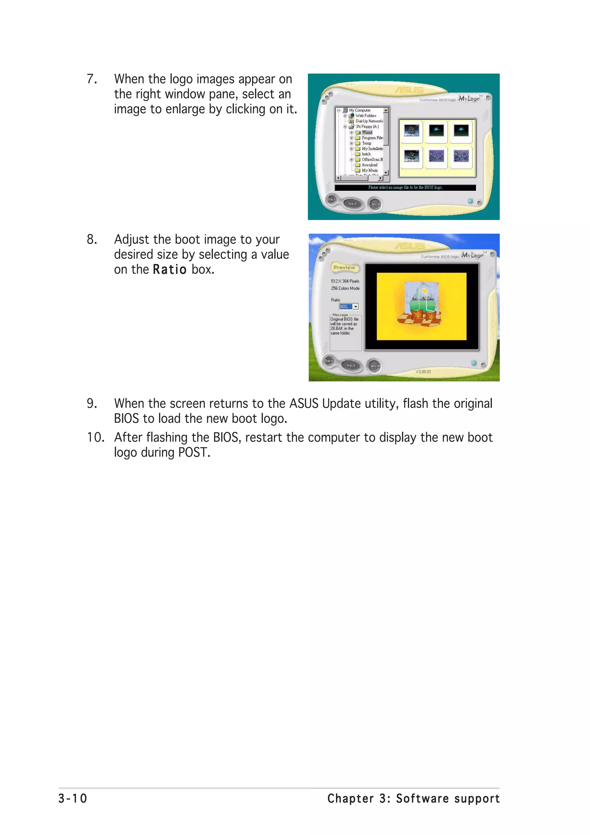
5. When prompted, locate the new
BIOS file, then click N e x t The t.
ASUS MyLogo2 window appears.
6. From the left window pane, select
the folder that contains the image
you intend to use as your boot
logo.
ASUS A8N-E 3-9](https://image.slidesharecdn.com/e1911a8n-e-130310080445-phpapp02/75/E1911-a8n-e-97-2048.jpg)
![Entering the NVIDIA® RAID utility
To enter the NVIDIA® RAID utility:
1. Boot up your computer.
2. During POST, press <F10> to display the main menu of the utility.
The RAID BIOS setup screens shown in this section are for reference
only, and may not exactly match the items on your screen.
NVIDIA RAID Utility Oct 5 2004
- Define a New Array -
RAID Mode: Striping Striping Block: Optimal
Free Disks Array Disks
Loc Disk Model Name Loc Disk Model Name
1.0.M XXXXXXXXXXXXXXXXXX
1.1.M XXXXXXXXXXXXXXXXXX [→] Add
2.0.M XXXXXXXXXXXXXXXXXX
2.1.M XXXXXXXXXXXXXXXXXX
[←] Del
[F6] Back [F7] Finish [TAB] Navigate [↑↓] Select [ENTER] Popup
At the bottom of the screen are the navigation keys. These keys allow you
to move through and select menu options.
Creating a RAID Volume
To create a RAID volume:
1. From the NVIDIA® RAID utility Define a New Array menu, select R A I D
M o d e then press <Enter>. The following submenu appears.
Use the up or down arrow keys to Mirroring
select a RAID mode then press Striping
<Enter>. Stripe Mirroring
Spanning
3-24 Chapter 3: Software support](https://image.slidesharecdn.com/e1911a8n-e-130310080445-phpapp02/75/E1911-a8n-e-112-2048.jpg)
![2. Press <TAB> select the Striping 8K ↑
Block then press <Enter>. The 16K
32K
following submenu appears: 64K
128K
Optim↓
If you selected Striping or Stripe Mirroring, use the up or down arrow
keys to select the stripe size for your RAID 0 array then press
<Enter>.The available values range from 8 KB to 128 KB. The default
selection is 128 KB. The strip value should be chosen based on the
planned drive usage.
• 8 /16 KB - low disk usage
• 64 KB - typical disk usage
• 128 KB - performance disk usage
T I P : For server systems, use of a lower array block size is
recommended. For multimedia computer systems used mainly for audio
and video editing, a higher array block size is recommended for optimum
performance.
3.` Press <TAB> to select the Free Disks area. Use the left or right arrow
keys to assign the array disks.
4. Press <F7> to create RAID set. The following message box appears.
Clear disk data?
[Y] YES [N]
5. Press <Y> to clear the selected disks or <N> to proceed without
clearing the disks. The following screen appears.
Take caution in using this option. All data on the RAID drives will be lost!
ASUS A8N-E 3-25](https://image.slidesharecdn.com/e1911a8n-e-130310080445-phpapp02/75/E1911-a8n-e-113-2048.jpg)
![NVIDIA RAID Utility Oct 5 2004
- Array List -
Boot Id Status Vendor Array Model Name
No 4 Healthy NVIDIA MIRROR XXX.XXG
[Ctrl-X]Exit [↑↓]Select [B]Set Boot [N]New Array [ENTER]Detail
A new set of navigation keys is displayed on the bottom of the
screen.
6. Press <Ctrl+X> to save settings and exit.
Rebuilding a RAID array
To rebuild a RAID array:
1. From the Array List menu, use the up or down arrow keys to select a
RAID array then press <Enter>. The RAID Array details appear.
Array 1 : NVIDIA MIRROR XXX.XXG
- Array Detail -
RAID Mode: Mirroring
Striping Width: 1 Striping Block: 64K
Adapt Channel M/S Index Disk Model Name Capacity
2 1 Master 0 XXXXXXXXXXXXXXXXX XXX.XXGB
1 0 Master 1 XXXXXXXXXXXXXXXXX XXX.XXGB
[R] Rebuild [D] Delete [C] Clear Disk [ENTER] Return
3-26 Chapter 3: Software support](https://image.slidesharecdn.com/e1911a8n-e-130310080445-phpapp02/75/E1911-a8n-e-114-2048.jpg)
![A new set of navigation keys is displayed on the bottom of the
screen.
2. Press <R> to rebuild a RAID array. The following screen appears.
Array 1 : NVIDIA MIRROR XXX.XXG
- Select Disk Inside Array -
RAID Mode: Mirroring
Striping Width: 1 Striping Block: 64K
Adapt Channel M/S Index Disk Model Name Capacity
2 1 Master 0 XXXXXXXXXXXXXXXXX XXX.XXGB
1 0 Master 1 XXXXXXXXXXXXXXXXX XXX.XXGB
[↑↓] Select [F6] Back [F7] Finish
3. Use the up or down arrow keys to select a RAID array to rebuild, then
press <F7>. The following confirmation message appears.
Rebuild array?
[ENTER] OK [ESC] Cancel
4. Press <Enter> to start rebuilding array or press <Esc> to cancel.
5. After the rebuild process, the Array list menu appears.
ASUS A8N-E 3-27](https://image.slidesharecdn.com/e1911a8n-e-130310080445-phpapp02/75/E1911-a8n-e-115-2048.jpg)
![Deleting a RAID array
To delete a RAID array:
1. From the Array List menu, use the up or down arrow keys to select a
RAID array then press <Enter>. The RAID Array details appear.
Array 1 : NVIDIA MIRROR XXX.XXG
- Array Detail -
RAID Mode: Mirroring
Striping Width: 1 Striping Block: 64K
Adapt Channel M/S Index Disk Model Name Capacity
2 1 Master 0 XXXXXXXXXXXXXXXXX XXX.XXGB
1 0 Master 1 XXXXXXXXXXXXXXXXX XXX.XXGB
[R] Rebuild [D] Delete [C] Clear Disk [ENTER] Return
A new set of navigation keys is displayed on the bottom of the
screen.
2. Press <D> to delete a RAID array. The following confirmation message
appears.
Delete this array?
[Y] YES [N] No
3. Press <Y> to delete array or press <N> to cancel.
Take caution in using this option. All data on the RAID drives will be lost!
4. If you selected Yes, the Define a New Array menu appears.
3-28 Chapter 3: Software support](https://image.slidesharecdn.com/e1911a8n-e-130310080445-phpapp02/75/E1911-a8n-e-116-2048.jpg)
![Clearing a disk data
To clear disk data:
1. From the Array List menu, use the up or down arrow keys to select a
RAID array then press <Enter>. The RAID Array details appear.
Array 1 : NVIDIA MIRROR XXX.XXG
- Array Detail -
RAID Mode: Mirroring
Striping Width: 1 Striping Block: 64K
Adapt Channel M/S Index Disk Model Name Capacity
2 1 Master 0 XXXXXXXXXXXXXXXXX XXX.XXGB
1 0 Master 1 XXXXXXXXXXXXXXXXX XXX.XXGB
[R] Rebuild [D] Delete [C] Clear Disk [ENTER] Return
A new set of navigation keys is displayed on the bottom of the
screen.
2. Press <C> to clear disk. The following confirmation message appears.
Clear disk data?
[Y] YES [N]
5. Press <Y> to clear the disk data or press <N> to cancel.
Take caution in using this option. All data on the RAID drives will be lost!
ASUS A8N-E 3-29](https://image.slidesharecdn.com/e1911a8n-e-130310080445-phpapp02/75/E1911-a8n-e-117-2048.jpg)