Downloaded 59 times


![SD 206-2.97
Page 23 of 62
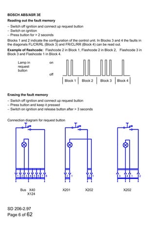
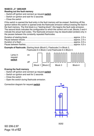
Type of fault Flashcode
Internal fault in control unit:
⇒ Control unit defective.........................................................................................................1
⇒ Cumulative test fault in calibration data, recalibrate displacement sensors......................2
⇒ Control unit defective.........................................................................................................3
⇒ Control unit defective.........................................................................................................4
⇒ Control unit defective.........................................................................................................5
⇒ Control unit defective.........................................................................................................6
⇒ Cumulative test fault in calibration data, recalibrate pressure sensor............................ (8)
⇒ Control unit or ECAS fuse, terminal 30, defective.............................................................9
Sensor fault, interruption or short-circuit to +UB:
⇒ Displacement sensor rear [front] right .............................................................................10
⇒ Displacement sensor rear [front] left ...............................................................................11
⇒ Displacement sensor front [centre]..................................................................................12
Pressure sensor, short-circuit to +UB ............................................................................... (15)
Anti-trap device contact strip, interruption or short-circuit to +UB..................................... (17)
Sensor fault, interruption or short-circuit to earth:
⇒ Displacement sensor rear [front] right .............................................................................20
⇒ Displacement sensor rear [front] left ...............................................................................21
⇒ Displacement sensor front [centre]..................................................................................22
Pressure sensor, short-circuit or interruption to earth ....................................................... (25)
Anti-trap device contact strip, short-circuit to earth........................................................... (27)
Fault in solenoid valve, interruption or short-circuit to +UB:
⇒ Central solenoid valve, reservoir A *...............................................................................30
⇒ Valve RA [FA] left C *......................................................................................................31
⇒ Valve RA [FA] right B *....................................................................................................32
⇒ Valve FA [CA] left F * ......................................................................................................33
⇒ Valve FA [CA] right E *....................................................................................................34
⇒ Bus-stop brake valve.................................................................................................... (35)
⇒ Valve for primary current throttle.................................................................................. (39)
⇒ Valve, transverse throttle D *........................................................................................ (70)
Solenoid valve fault, interruption or short-circuit to earth:
⇒ Central solenoid valve, reservoir A *...............................................................................40
⇒ Valve RA [FA] left C *......................................................................................................41
⇒ Valve RA [FA] right B *....................................................................................................42
⇒ Valve FA [CA] left F * ......................................................................................................43
⇒ Valve FA [CA] right E *....................................................................................................44
⇒ Bus-stop brake valve.................................................................................................... (45)
⇒ Valve, primary current throttle ...................................................................................... (49)
⇒ Valve, transverse throttle D *........................................................................................ (71)
[ ] For the forebody of articulated buses the data in the square brackets apply.
( ) For vehicles with this equipment.
* The letter is on the corrugated tube of the relevant valve.](https://image.slidesharecdn.com/manf2000codes-141206213922-conversion-gate01/85/Man-f2000-codes-23-320.jpg)
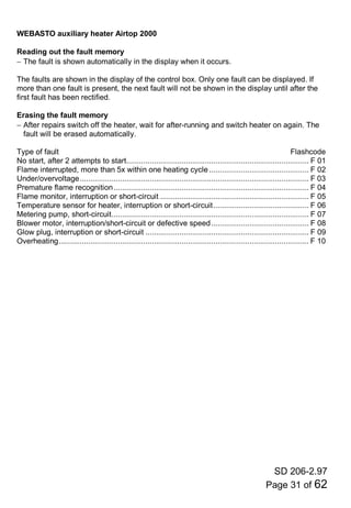
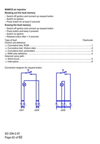
![SD 206-2.97
Page 24 of 62
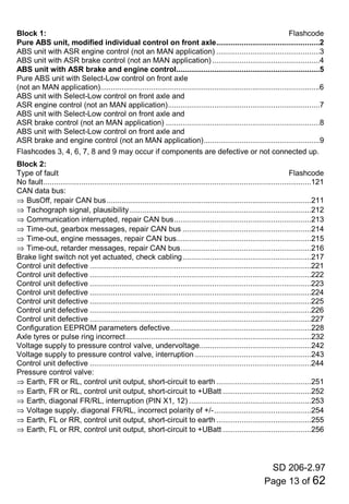
Type of fault Flashcode
Relay, door release:
⇒ Interruption or short-circuit to +UB ............................................................................... (36)
⇒ Short-circuit to earth..................................................................................................... (46)
Plausibility fault (mechanical fault) during raising:
⇒ Displacement sensor rear [front] right .............................................................................50
⇒ Displacement sensor rear [front] left ...............................................................................51
⇒ Displacement sensor front [centre]..................................................................................52
Plausibility fault (mechanical fault) during lowering:
⇒ Displacement sensor rear [front] right .............................................................................60
⇒ Displacement sensor rear [front] left ...............................................................................61
⇒ Displacement sensor front [centre]..................................................................................62
Control unit defective ...........................................................................................................80
Speed signal interruption or short-circuit to +UB .................................................................81
[ ] For the forebodies of articulated buses the data in square brackets apply.
( ) For vehicles with this equipment.
* The letter is on the corrugated tube of the relevant valve.](https://image.slidesharecdn.com/manf2000codes-141206213922-conversion-gate01/85/Man-f2000-codes-24-320.jpg)


This document provides flashcodes for fault memories for various vehicle systems, including ABS/ASR systems from Bosch, running gear controls, transmission systems, heating/air conditioning, engines, and other components. It includes tables of flashcodes for specific systems that indicate things like the control unit configuration, component faults, sensor issues, electrical problems, and other diagnostic information. The flashcodes are emitted in sets of lights or blocks during fault memory readings and can be cleared by pressing a request button for a certain duration while turning the ignition on.


![Jcb 210 e+sistema+hidráulico[1]](https://cdn.slidesharecdn.com/ss_thumbnails/jcb210esistemahidrulico1-220221233216-thumbnail.jpg?width=640&height=640&fit=bounds)


![[English Version]Maker-Ray Product Brochure V3 .pdf](https://cdn.slidesharecdn.com/ss_thumbnails/englishversionmaker-rayproductbrochurev3-260113094444-0156dbdc-thumbnail.jpg?width=640&height=640&fit=bounds)


