Downloaded 63 times
![Tutorial Series
! Lecture 1: Introduction to UML:
Structural and Use Case Modeling
! Lecture 2: Behavioral Modeling with
UML
! Lecture 3: Advanced Modeling with UML
[Note: This version of the tutorial series is based on OMG UML
Specification v. 1.4, OMG doc# ad/01-02-13, adopted in May 2001.]
Introduction to UML 3](https://image.slidesharecdn.com/01-1kobrynstructuralandusecasemodelingtutorial-120914042828-phpapp02/85/01-1-kobryn-structural_and_use_case_modeling_tutorial-3-320.jpg)
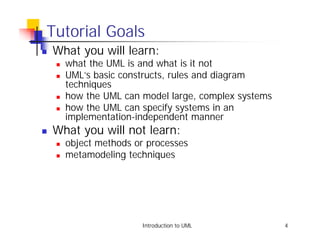

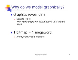
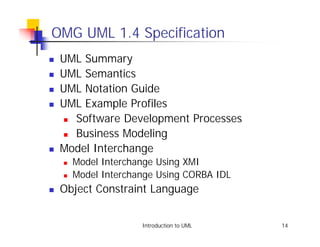
![OMG UML Evolution
2002
(planned)
<<document>>
UML 2.0
<<document>>
<<document>>
UML 2.0
UML 2.0
Diagram
Superstructure
<<document>> Interchange
<<document>>
UML 2.0
UML 2.0 OCL
Infrastructure
<<document>>
Q2 2001 UML 1.4
Editorial revision
without significant
technical changes.
<<document>>
1999 UML 1.3
<<document>>
1998 UML 1.2
<<document>>
1997 UML 1.1
Updated from
(adopted by OMG) [Kobryn 01a].
Introduction to UML 12](https://image.slidesharecdn.com/01-1kobrynstructuralandusecasemodelingtutorial-120914042828-phpapp02/85/01-1-kobryn-structural_and_use_case_modeling_tutorial-12-320.jpg)
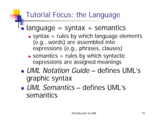
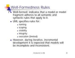
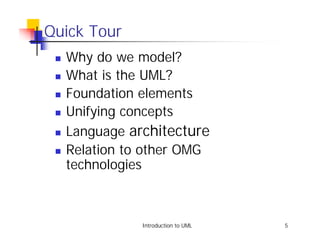
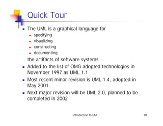
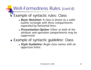
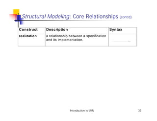
![Well-Formedness Rules (cont’d)
! Example of semantic rule: Class [1]
! English: If a Class is concrete, all the
Operations of the Class should have a realizing
Method in the full descriptor.
! OCL: not self.isAbstract implies
self.allOperations->
forAll (op | self.allMethods->
exists (m | m.specification-> includes(op)))
Introduction to UML 21](https://image.slidesharecdn.com/01-1kobrynstructuralandusecasemodelingtutorial-120914042828-phpapp02/85/01-1-kobryn-structural_and_use_case_modeling_tutorial-21-320.jpg)
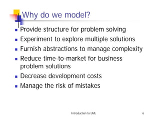
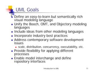
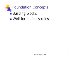
![Metamodel Architecture
<<metamodel>>
MOF Meta-Metamodel
«metaclass» «metaclass» «metaclass»
Attribute Class Operation
«instanceOf» «instanceOf»
<<use>>
«instanceOf»
<<metamodel>>
UML Metamodel
«metaclass» «metaclass» «metaclass»
Attribute Class Operation
«instanceOf»
<<use>>
Analysis Model The operation
issue of the
The attribute fare of
PassengerTicket
the PassengerTicket
PassengerTicket class is an
class is an instance of
instance of the
the metaclass
-issuedBy : Airline metaclass
Attribute.
-issuingAgent : TravelAgent Operation.
-fare : Currency
-tax : Currency
+total()
+issue()
+surrender()
+refund()
From [Kobryn 01b].
«instanceOf»
45723990550: PassengerTicket Represents the
User Object layer
of the 4-layer
-issuedBy : Airline = AcmeAirlines metamodel
-issuingAgent : TravelAgent = TerrificTravel architecture
-fare : Currency = 1050.00 pattern.
-tax : Currency = 57.56
Introduction to UML 25](https://image.slidesharecdn.com/01-1kobrynstructuralandusecasemodelingtutorial-120914042828-phpapp02/85/01-1-kobryn-structural_and_use_case_modeling_tutorial-25-320.jpg)
![UML Metamodel Layer
Behavioral Elements
Activity Graphs
package
Collaborations Use Cases State Machines Model Management
Common Behavior
dependency
Foundation
Core Extension Mechanisms
Data Types
From [Kobryn 01b].
Introduction to UML 26](https://image.slidesharecdn.com/01-1kobrynstructuralandusecasemodelingtutorial-120914042828-phpapp02/85/01-1-kobryn-structural_and_use_case_modeling_tutorial-26-320.jpg)
![Relationships to Other Modeling Technologies
Metadata layer Meta Object XMI
Facility Facility
<<document>>
UML XMI DTD
Unified
Specification
Modeling
layer
Language
<<document>>
UML CORBA IDL
Customization UML Profile UML Profile
layer for CORBA for Telecom
Platform Domain
technology technology
profiles profiles
From [Kobryn 01b].
Introduction to UML 27](https://image.slidesharecdn.com/01-1kobrynstructuralandusecasemodelingtutorial-120914042828-phpapp02/85/01-1-kobryn-structural_and_use_case_modeling_tutorial-27-320.jpg)
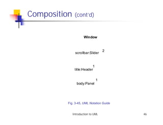
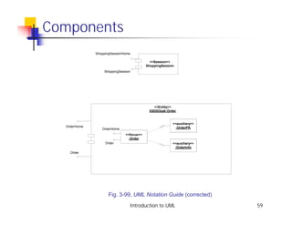
![Composition
Window
scrollbar [2]: Slider
title: Header
body: Panel
Window
1
1 1
scrollbar 2 title 1 body 1
Slider Header Panel
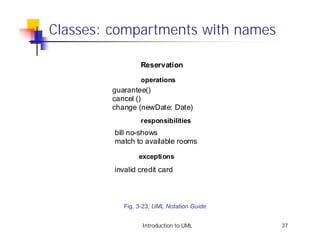
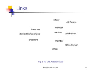
Fig. 3-45, UML Notation Guide
Introduction to UML 45](https://image.slidesharecdn.com/01-1kobrynstructuralandusecasemodelingtutorial-120914042828-phpapp02/85/01-1-kobryn-structural_and_use_case_modeling_tutorial-45-320.jpg)
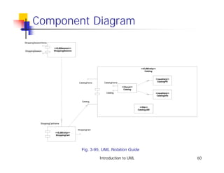
![Class Diagram Example
CreditCard
PMCreditCard
{abstract}
OrderBean
<<interface>> {abstract}
EntityBean
+getOrderStatus
+setOrderStatus
PMOrder
+getLineItems
+setLineItems
order +getCreditApproved
+setCreditApproved
* ...
1 order
buyer 1 * item
Customer LineItem
PMLineItem
{abstract}
*
* item
1 commodity
Product
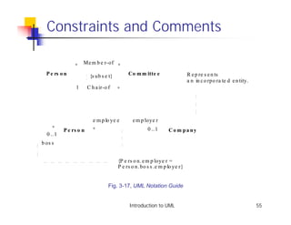
Adapted from Fig. 23 [EJB 2.0].
Introduction to UML 56](https://image.slidesharecdn.com/01-1kobrynstructuralandusecasemodelingtutorial-120914042828-phpapp02/85/01-1-kobryn-structural_and_use_case_modeling_tutorial-56-320.jpg)
![Example: Point-of-Sale
! The following example shows how UML can
model the interfaces for a Point of Sale
application originally specified in CORBA IDL.
From [Kobryn 01b].
Introduction to UML 67](https://image.slidesharecdn.com/01-1kobrynstructuralandusecasemodelingtutorial-120914042828-phpapp02/85/01-1-kobryn-structural_and_use_case_modeling_tutorial-67-320.jpg)
![Point-of-Sale Example
module POS
{
typedef long POSId;
typedef string Barcode;
interface InputMedia
{
typedef string OperatorCmd;
void BarcodeInput(in Barcode Item);
void KeypadInput(in OperatorCmd Cmd);
};
interface OutputMedia
{...};
interface POSTerminal
{...};
};
...
Ch. 26, CORBA Fundamentals and Programming (2nd ed.), [Siegel 00]
Introduction to UML 68](https://image.slidesharecdn.com/01-1kobrynstructuralandusecasemodelingtutorial-120914042828-phpapp02/85/01-1-kobryn-structural_and_use_case_modeling_tutorial-68-320.jpg)
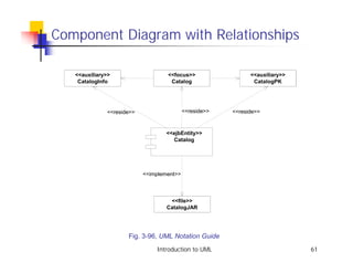
![POS Class Diagram
Point_Of_Sale
«CORBAInterface»
«CORBAInterface» IInputMedia
IPOSterminal -POSref : POSterminal
InputMedia
-storeRef : Store +initialization()
-storeAccessRef : StoreAccess +barcodeInput()
-outputMediaRef : OutputMedia +keypadInput()
-taxRef : Tax
«CORBAInterface»
-POSid : Integer
IOutputMedia
-itemBarcode : Integer
OutputMedia
-itemQuantity : Integer «CORBAInterface»
-itemInfo : ItemInfo IStore
+outputText()
-itemPrice : Currency
-itemTaxPrice : Currency -totals : Totals
-itemExtension : Currency -POSlist : List
-saleSubtotal : Currency +initialization()
-taxableSubtotal : Currency +login()
-saleTotal : Currency +getPOStotals()
POSterminal
-saleTax : Currency +updateStoreTotals()
-POSlist : List +getTotals()
+initialization() +getStoreId()
+login()
+printPOSsalesSummary()
+printStoreSalesSummary()
+setItemQuantity()
+sendBarcode() class longhand notation
+endSale() for interface Store
«CORBAInterface»
«CORBAInterface» IStoreAccess
ITax
-depotRef :
Tax -rate : float -taxRef : Tax
+initialization() -storeMarkup : float
+calculateTax() StoreAccess -storeId : Integer
+findTaxablePrice() +initialization()
+findPrice()
«CORBAInterface»
IDepot
Depot
+intialization()
+findItemInfo()
From [Kobryn 2001b]
Introduction to UML 69](https://image.slidesharecdn.com/01-1kobrynstructuralandusecasemodelingtutorial-120914042828-phpapp02/85/01-1-kobryn-structural_and_use_case_modeling_tutorial-69-320.jpg)
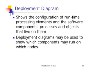
![POS Deployment Diagram
shorthand
node ("lollipop") component.
notation for
interface.
station3:POSStation :StoreServer
ITax
:InputMedia :Tax
IInputMedia
IStore
:POSterminal :Store
IPOSterminal
:OutputMedia :StoreAccess
IOutputMedia IStoreAccess
<<ethernet>> <<ethernet>>
<<network>>
:LocalAreaNetwork
<<ethernet>> <<ethernet>> <<ethernet>>
:POSstation :DBServer :POSstation
:Depot
IDepot
From [Kobryn 2001b]
Introduction to UML 70](https://image.slidesharecdn.com/01-1kobrynstructuralandusecasemodelingtutorial-120914042828-phpapp02/85/01-1-kobryn-structural_and_use_case_modeling_tutorial-70-320.jpg)
![Model Fragment from POS Example
«CORBAInterface»
ITax
Tax -rate : float
+initialization()
+calculateTax()
+findTaxablePrice()
From [Kobryn 2001b]
Introduction to UML 71](https://image.slidesharecdn.com/01-1kobrynstructuralandusecasemodelingtutorial-120914042828-phpapp02/85/01-1-kobryn-structural_and_use_case_modeling_tutorial-71-320.jpg)
![XML Generated by XMI Facility
<XMI xmi.version = '1.1' xmlns:UML='//org.omg/UML/1.3' ...>
<XMI.header>
<XMI.metamodel xmi.name = 'UML' xmi.version = '1.3'/>
</XMI.header>
<XMI.content>
<!-- POS_Example_R2 [Model] -->
<UML:Model xmi.id = 'G.0'
name = 'POS_Example_R2' visibility = 'public' isSpecification =
'false'
isRoot = 'false' isLeaf = 'false' isAbstract = 'false' >
<UML:Namespace.ownedElement>
<!-- POS_Example_R2::Tax [Class] -->
<UML:Class xmi.id = 'S.1'
name = 'Tax' visibility = 'public' isSpecification = 'false'
isRoot = 'true' isLeaf = 'true' isAbstract = 'false'
isActive = 'false' From [Kobryn 2001b]
namespace = 'G.0' clientDependency = 'G.1' />
... Introduction to UML 72](https://image.slidesharecdn.com/01-1kobrynstructuralandusecasemodelingtutorial-120914042828-phpapp02/85/01-1-kobryn-structural_and_use_case_modeling_tutorial-72-320.jpg)
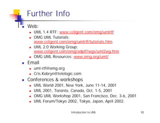
![References
! [UML 1.4] OMG UML Specification v. 1.4, UML Revision Task Force,
OMG doc# ad/01-02-13.
! [Kobryn 01a] C. Kobryn, “UML 2.0 Roadmap: Fast Track or Detours?,”
Software Development, April 2001.
! [Kobryn 01b] C. Kobryn, “Modeling Distributed Applications with UML,”
Part IV: Chapter 1 in [Siegel 01] Quick CORBA 3, Wiley, 2001.
! [Kobryn 00] “Modeling CORBA Applications with UML,” chapter 21 in
[Siegel 00] CORBA 3 Fundamentals and Programming (2nd ed.), Wiley,
2000.
! [Kobryn 99] UML 2001: A Standardization Odyssey, Communications of
the ACM, Oct. 1999.
! [EJB 2.0] Enterprise JavaBeans Specification v. 2.0, Sun Microsystems,
March 31, 2000.
Introduction to UML 91](https://image.slidesharecdn.com/01-1kobrynstructuralandusecasemodelingtutorial-120914042828-phpapp02/85/01-1-kobryn-structural_and_use_case_modeling_tutorial-91-320.jpg)

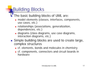
This document provides an introduction to structural and use case modeling with the Unified Modeling Language (UML). It outlines a tutorial series on UML that covers introduction, behavioral modeling, and advanced modeling. The document discusses why modeling is useful, provides an overview of UML's goals and evolution, and describes some of UML's foundational concepts including its building blocks, well-formedness rules, and unifying concepts.