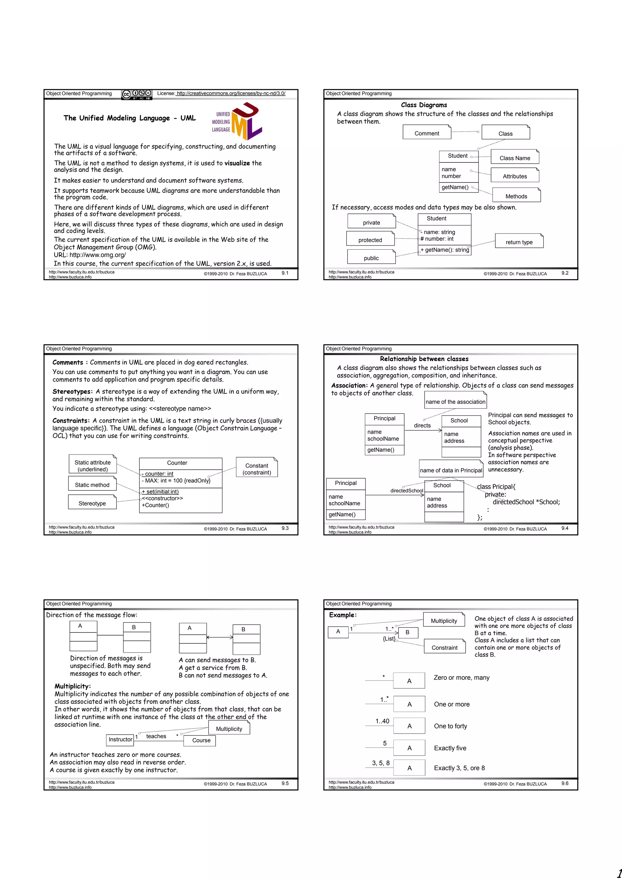
The document discusses object-oriented programming and Unified Modeling Language (UML) diagrams. It describes three types of UML diagrams: class diagrams, which show the structure of classes and relationships between them; communication diagrams, which illustrate object interactions; and sequence diagrams, which show the sequence and timing of messages between objects. It provides examples of different UML concepts like associations, aggregations, generalizations, conditional messages, and iteration.
![Object Oriented Programming License: http://creativecommons.org/licenses/by-nc-nd/3.0/ Object Oriented Programming
Sequence numbers of messages: msg1()
Messages to “self” or “this”:
The external message is not numbered.
Nested message A message can be sent from an object to itself.
It is sent in the :AnyClass
method of msg2
First Second
Creation of Instances:
Third Any message can be used to create an instance, but there
msg1() 1: msg2() 1: clear()
:ClassA :ClassB is a convention in the UML to use a message named create
for this purpose (some use new).
1.1: msg3()
If another message name is used, the message may be
2.1: msg5() A B C D annotated with a stereotype, like so: «create».
2: msg4() msg1()
:ClassC msg2() The create message may include parameters, indicating the
Fifth
msg3() passing of initial values. This indicates, a constructor call
1:
1.1:
with parameters.
Fourth 2.2: msg6()
1: create()
: School :Course {new}
msg4()
Sixth :ClassD
2:
msg5()
msg6() «create»
2.1: 1: make()
2.2: : School :Course {new}
http://www.faculty.itu.edu.tr/buzluca ©1999-2010 Dr. Feza BUZLUCA 9.13 http://www.faculty.itu.edu.tr/buzluca ©1999-2010 Dr. Feza BUZLUCA 9.14
http://www.buzluca.info http://www.buzluca.info
Object Oriented Programming Object Oriented Programming
Conditional Messages: Iteration or Looping:
The message is only sent if the clause evaluates to true.
iteration is indicated with a * and an optional
Conditional message
iteration clause following the sequence number
message1()
runSimulation ()
1 [ color = red ] : calculate()
:ClassA : ClassB 1 * [i:=1..N ] : num := nextInt()
: Simulator :Random
Mutually Exclusive Paths:
Message flows between objects may follow different paths according to some
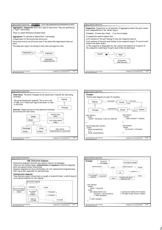
Iteration Over a Collection (Multiobject):
conditions.
A common algorithm is to iterate over all members of a collection (such as a list or
In the example there are two path according to condition "test" : a or b .
map), sending a message to each.
Unconditionally after :ClassE 1a and 1b are mutually
either msg2 or msg4 exclusive paths
In the UML, the term “multiobject” is used to denote a set of instances.
2: msg6()
This box represents one instance
msg1() 1a [test] : msg2() from a collection of many
:ClassA :ClassB Course objects
avg := getAverage ()
1 * [i:=1..N ] : grade := getGrade() courses[i]:
1b [not test] : msg4() 1a.1: msg3() : Student Course
1b.1: msg5()
:ClassD :ClassC optional
http://www.faculty.itu.edu.tr/buzluca ©1999-2010 Dr. Feza BUZLUCA 9.15 http://www.faculty.itu.edu.tr/buzluca ©1999-2010 Dr. Feza BUZLUCA 9.16
http://www.buzluca.info http://www.buzluca.info
Object Oriented Programming Object Oriented Programming
Sequence diagrams: Example: Object
Creates a new object
Sequence diagrams also illustrate the interactions between objects. Constructor call
Message
They clearly show sequence or time ordering of messages. : School :Teacher
Any instance Object nb New Object
(object) of ClassB openCourse(crn)
of Class A
openCourse(crn)
sd Example create(crn)
: Course
:ClassAInstance nb:ClassBInstance
message1()
Name of the diagram : ClassA : ClassB
sd: Sequence Illustrating Reply or Returns:
message2()
diagram A sequence diagram may optionally msg1()
show the return from a message as a reply := getSomething()
message3()
dashed open-arrowed line at the end
of an activation box. getSomething()
There are two ways to show the reply
return result from a message: msg4()
1. Using the message syntax:
Body (lifetime) Lifeline of the returnVar := message (parameter) msg5()
of the method object 2. Using a reply (return) message line.
http://www.faculty.itu.edu.tr/buzluca ©1999-2010 Dr. Feza BUZLUCA 9.17 http://www.faculty.itu.edu.tr/buzluca ©1999-2010 Dr. Feza BUZLUCA 9.18
http://www.buzluca.info http://www.buzluca.info
3](https://image.slidesharecdn.com/oop096-100415094827-phpapp02/85/Oop09-6-3-320.jpg)
![Object Oriented Programming License: http://creativecommons.org/licenses/by-nc-nd/3.0/ Object Oriented Programming
Conditional Messages:
Messages to “self” or “this”: :Counter To support conditional and looping constructs, the UML uses frames.
A message can be sent from an object to itself. msg1() Frames are regions or fragments of the diagrams; they have an operator or label
clear() (such as loop or opt) and a guard (conditional clause).
In order to illustrate conditional messages an opt frame is placed around one or
Object Destruction: more messages.
In some circumstances it is desirable to show explicit
destruction of an object (as in C++, which does not have
garbage collection). sd if-then
In this case delete operator is used and destructor of the :A :B
Label
target object is called.
msg1()
The «destroy» stereotyped msg x
:Admin message, with the large
X and short lifeline Frame opt [color = blue]
if condition is true calculate()
indicates explicit object
create(crn) destruction
:Course msg y
....
<<destroy>>
X
http://www.faculty.itu.edu.tr/buzluca ©1999-2010 Dr. Feza BUZLUCA 9.19 http://www.faculty.itu.edu.tr/buzluca ©1999-2010 Dr. Feza BUZLUCA 9.20
http://www.buzluca.info http://www.buzluca.info
Object Oriented Programming Object Oriented Programming
Mutually Exclusive Conditional Messages : Looping:
An alt frame is placed around the mutually exclusive alternatives.
:Simulator :Random :Programmer
runSimulation()
sd if-then-else
:A :B :C loop [i:=1..N]
msg1() hours := nextInt()
Guard
alt [x<10] Continuation condition work(hours)
calculate()
[else]
calculate() eat()
Borders of
The for loop
http://www.faculty.itu.edu.tr/buzluca ©1999-2010 Dr. Feza BUZLUCA 9.21 http://www.faculty.itu.edu.tr/buzluca ©1999-2010 Dr. Feza BUZLUCA 9.22
http://www.buzluca.info http://www.buzluca.info
Object Oriented Programming Object Oriented Programming
Iteration Over a Collection (Multiobject): Interaction of diagrams :
Reference frames are used to simplify a diagram and factor out a portion into another
A common algorithm is to iterate over all members of a collection (such as a list or diagram, or if there is a reusable interaction occurrence.
map), sending a message to each. It is like calling subroutines.
In the UML, the term “multiobject” is used to denote a set of instances. sd interaction
:A :B :C
myCourses[i]
:Student :Course msg1()
msg1()
avg := getAverage ()
ref
loop [i<myCourses.size] Operation
grade := getGrade()
i++ msg2()
sd Operation
:B :C
An optional activation box
may contain arbitrary msg x()
language statements
msg y()
msg z()
http://www.faculty.itu.edu.tr/buzluca ©1999-2010 Dr. Feza BUZLUCA 9.23 http://www.faculty.itu.edu.tr/buzluca ©1999-2010 Dr. Feza BUZLUCA 9.24
http://www.buzluca.info http://www.buzluca.info
4](https://image.slidesharecdn.com/oop096-100415094827-phpapp02/85/Oop09-6-4-320.jpg)