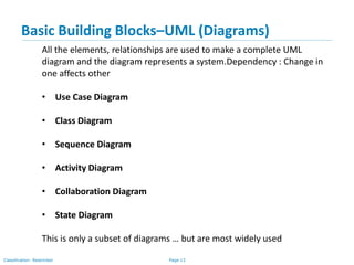
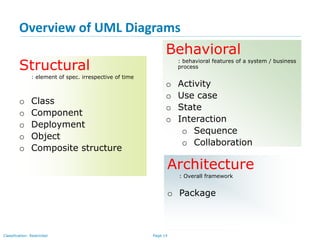
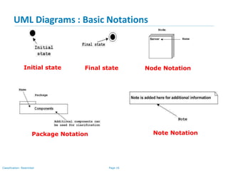
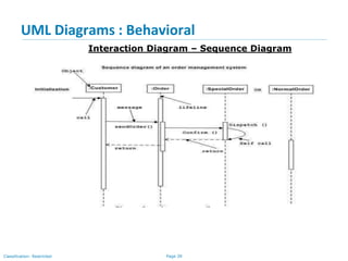
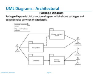
Business Analysis
Training
UML And Use Case Study
Page 2Classification: Restricted
Agenda
• UML - Unified Modeling Language
• Modeling
• Why UML for Modeling
• Object Oriented Concepts
• Object Oriented Modeling
• Basic Building blocks -UML
• Overview of UML Diagrams
• UML Diagrams - Basic Notations
• UML Diagrams - Relationships
• UML Diagrams - Structural diagram
• UML Diagrams - Behavioral diagram
• UML Diagrams - Architectural
Page 3Classification: Restricted
UML - Unified Modeling Language
• UML (Unified Modeling Language) is a standard language for
specifying, visualizing, constructing, and documenting the artifacts of
software systems.
• UML is a pictorial language used to make software blueprints.
• The UML uses mostly graphical notations to express the OO analysis
and design of software projects.
• UML can be described as the successor of object-oriented (OO)
analysis and design.
Page 4Classification: Restricted
Modeling
• Describing a system at a high level of abstraction
– A model of the system
– Used for requirements and specifications
• Is it necessary to model software systems?
Page 5Classification: Restricted
Why UML for Modeling
• Use graphical notation to communicate more clearly than natural
language (imprecise) and code(too detailed).
• Help acquire an overall view of a system.
• UML is not dependent on any one language or technology.
• UML moves us from fragmentation to standardization.
Page 6Classification: Restricted
Object Oriented Concepts
Following are some fundamental concepts of the object-oriented world
Objects − Objects represent an entity and the basic building block. An object
contains both data and methods that control the data.
Class − Class is the blue print of an object.
Abstraction − Abstraction represents the behaviour of an real world entity.
Encapsulation − Encapsulation is the mechanism of binding the data together
and hiding them from the outside world.
Inheritance − Inheritance is the mechanism of making new classes from
existing ones.
Polymorphism − It defines the mechanism to exists in different forms.
Page 7Classification: Restricted
Object Oriented Modeling
Page 8Classification: Restricted
Basic Building blocks -UML
The building blocks of UML can be defined as −
• Things
• Relationships
• Diagrams
Page 9Classification: Restricted
Basic Building Blocks – UML ( Things)
• Structural
• Behavioural
• Grouping
• Annotation
Structural : Static parts of UML models
Physical and conceptual models
Page 10Classification: Restricted
Basic Building Blocks – UML ( Things)
Behavioural : dynamic parts of UML models.
Interaction − Interaction is defined as a behaviour that consists of a group of
messages exchanged among elements to accomplish a specific task.
State machine − It defines the sequence of states an object goes through in
response to events. Events are external factors responsible for state change
Page 11Classification: Restricted
Basic Building Blocks–UML (Things)
Grouping : Group elements of a UML model together.
Package is the only one grouping thing available for gathering structural
and behavioral things.
Annotations : Mechanism to capture remarks, descriptions, and
comments of UML model elements.
Page 12Classification: Restricted
Basic Building Blocks–UML (Relationships)
Relationship reflects the association between the elements
• Dependency : Change in one affects other
------------------->
• Association : set of links that connects the elements of a UML model
• Generalizations : Representing inheritance
• Realization : Representing Interface. One element describes some
responsibility, which is not implemented and the other one
implements them
Page 13Classification: Restricted
Basic Building Blocks–UML (Diagrams)
All the elements, relationships are used to make a complete UML
diagram and the diagram represents a system.Dependency : Change in
one affects other
• Use Case Diagram
• Class Diagram
• Sequence Diagram
• Activity Diagram
• Collaboration Diagram
• State Diagram
This is only a subset of diagrams … but are most widely used
Page 14Classification: Restricted
Structural
: element of spec. irrespective of time
o Class
o Component
o Deployment
o Object
o Composite structure
Overview of UML Diagrams
Behavioral
: behavioral features of a system / business
process
o Activity
o Use case
o State
o Interaction
o Sequence
o Collaboration
Architecture
: Overall framework
o Package
Page 15Classification: Restricted
UML Diagrams : Basic Notations
Class Notation
Object Notation
Interface Notation Collaboration Notation
Actor
Page 16Classification: Restricted
UML Diagrams : Basic Notations
Initial state Node Notation
Package Notation Note Notation
Final state
Page 17Classification: Restricted
UML Diagrams - Relationships
• There are two kinds of Relationships
• Generalization (parent-child relationship)
• Association (student enrolls in course)
• Associations can be further classified as
• Aggregation
• Composition
Page 18Classification: Restricted
UML Diagrams - Structural Diagram
Class Diagram
• Used to model the static view of an application.
• Describing responsibilities of a system
• Provide a conceptual model of the system in terms of entities and their
relationships
• Used for requirement capture, end-user interaction
• Base for component and deployment diagrams
Page 19Classification: Restricted
UML Diagrams – Structural Diagram
The following points should be remembered while drawing a class diagram −
• The name of the class diagram should be meaningful to describe the
aspect of the system.
• Each element and their relationships should be identified in advance.
• Responsibility (attributes and methods) of each class should be clearly
identified
• For each class, minimum number of properties should be specified, as
unnecessary properties will make the diagram complicated.
• Use notes whenever required to describe some aspect of the diagram. At
the end of the drawing it should be understandable to the
developer/coder.
• Finally, before making the final version, the diagram should be drawn on
plain paper and reworked as many times as possible to make it correct.
Class Diagram
Page 20Classification: Restricted
UML Diagrams – Structural Diagram
• Each class is represented by a rectangle subdivided into three
compartments
• Name
• Attributes
• Operations
• Modifiers are used to indicate visibility of attributes and operations.
• ‘+’ is used to denote Public visibility (everyone)
• ‘#’ is used to denote Protected visibility (friends and derived)
• ‘-’ is used to denote Private visibility (no one)
• By default, attributes are hidden and operations are visible.
Class Diagram
Page 21Classification: Restricted
UML Diagrams – Structural Diagrams
Account_Name
- Customer_Name
- Balance
+addFunds( )
+withDraw( )
+transfer( )
Name
Attributes
Operations
Class Diagram
Representation of a Class
Page 22Classification: Restricted
UML Diagrams – Structural Diagram
Class Diagram
Page 23Classification: Restricted
UML Diagrams : Structural
Object Diagram
• Object diagrams represent an instance of a class diagram
• The purpose of the object diagram can be summarized as −
• Object relationships of a system
• Static view of an interaction.
• Understand object behaviour and their relationship from
practical perspective.
• Object diagrams are drawn in following manner:
• First, analyze the system and decide which instances have
important data and association.
• Second, consider only those instances, which will cover the
functionality.
• Third, make some optimization as the number of instances
are unlimited.
Page 24Classification: Restricted
UML Diagrams : Structural
Object Diagram
Page 25Classification: Restricted
UML Diagrams : Structural
Component Diagram
• Component diagrams are used to model the physical aspects of a
system such as files, libraries etc..
• It does not describe the functionality of the system but it describes the
components used to make those functionalities.
• Before drawing a component diagram, the following artifacts are to be
identified clearly −
• Files used in the system.
• Libraries and other artefacts relevant to the application.
• Relationships among the artefacts.
• After identifying the artefacts, the following points need to be kept in
mind.
• Use a meaningful name to identify the component for which the
diagram is to be drawn.
• Prepare a mental layout before producing the using tools.
• Use notes for clarifying important points.
Page 26Classification: Restricted
UML Diagrams : Structural
Component Diagram
Page 27Classification: Restricted
UML Diagrams : Structural
Deployment Diagram
The purpose of deployment diagrams can be described as −
• Visualize the hardware topology of a system.
• Describe the hardware components used to deploy software
components.
• Describe the runtime processing nodes.
Before drawing a deployment diagram, the following artefacts should
be identified −
• Nodes
• Relationships among nodes
Deployment diagrams can be used −
• To model the hardware topology of a system.
• To model the embedded system.
• To model the hardware details for a client/server system.
• To model the hardware details of a distributed application.
Page 28Classification: Restricted
UML Diagrams : Structural
Deployment Diagram
Page 29Classification: Restricted
UML Diagrams : Behavioral
Use Case Diagram
To model a system, the most important aspect is to capture the
dynamic behavior. Dynamic behavior means the behavior of the
system when it is running/operating.
The purposes of use case diagrams can be said to be as follows −
• Used to gather the requirements of a system.
• Used to get an outside view of a system.
• Identify the external and internal factors influencing the
system.
• Show the interaction among the requirements are actors.
When we are planning to draw a use case diagram, we should have
the following items identified.
• Functionalities to be represented as use case
• Actors
• Relationships among the use cases and act
Page 30Classification: Restricted
UML Diagrams : Behavioral
Use Case Diagram
Following guidelines to draw an efficient use case diagram
• The name of a use case is very important. The name should be
chosen in such a way so that it can identify the functionalities
performed.
• Give a suitable name for actors.
• Show relationships and dependencies clearly in the diagram.
• Do not try to include all types of relationships, as the main purpose
of the diagram is to identify the requirements.
• Use notes whenever required to clarify some important points.
** Use Case Diagrams are used to showcase the high level design of
the system.
Page 31Classification: Restricted
UML Diagrams : Behavioral
Use Case Diagram
Page 32Classification: Restricted
UML Diagrams : Behavioral
Use Case Diagram
Library System
Borrow
Order Title
Fine Remittance
Client
Employee
Supervisor
Boundary
Actor
Use Case
Page 33Classification: Restricted
UML Diagrams : Behavioral
Activity Diagram
Activity diagram is basically a flowchart to represent the flow from
one activity to another activity.
The purpose of an activity diagram can be described as −
• Draw the activity flow of a system.
• Describe the sequence from one activity to another.
• Describe the parallel, branched and concurrent flow of the
system.
Before drawing an activity diagram, we should identify the
following elements −
• Activities
• Association
• Conditions
• Constraints
Page 34Classification: Restricted
UML Diagrams : Behavioral
Activity Diagram
Page 35Classification: Restricted
UML Diagrams - Behavioral
State Diagrams show the sequences of states an object goes through during
its life cycle in response to stimuli, together with its responses and actions;
an abstraction of all possible behaviors.
Unpaid
Start End
Paid
Invoice created payin
g
Invoice destroying
State Diagram
Page 36Classification: Restricted
UML Diagrams – Behavioral
State Diagram
Page 37Classification: Restricted
UML Diagrams – Behavioral
Yellow
Red
Green
Traffic Light
State
Transition
Event
Star
t
State Diagram
Page 38Classification: Restricted
UML Diagrams : Behavioral
Interaction Diagram – Sequence Diagram
This interactive behavior is represented in UML by two diagrams known
as Sequence diagram and Collaboration diagram
The purpose of interaction diagram is −
• To capture the dynamic behaviour of a system.
• To describe the message flow in the system.
• To describe the structural organization of the objects.
• To describe the interaction among objects.
Following things are to be identified clearly before drawing the interaction
diagram
• Objects taking part in the interaction.
• Message flows among the objects.
• The sequence in which the messages are flowing.
• Object organization.
Page 39Classification: Restricted
UML Diagrams : Behavioral
Interaction Diagram – Sequence Diagram
Page 40Classification: Restricted
UML Diagram - Behavioral
Caller Phone Recipient
Picks up
Dial tone
Dial
Ring notification Ring
Picks up
Hello
Interaction Diagram – Sequence Diagram
Page 41Classification: Restricted
UML Diagrams : Behavioral
Interaction Diagram – Collaboration Diagram
Method calls are similar to that of a sequence diagram. However, difference
being the sequence diagram does not describe the object organization,
whereas the collaboration diagram shows the object organization.
Page 42Classification: Restricted
UML Diagrams : Architectural
Package Diagram
Package diagram is UML structure diagram which shows packages and
dependencies between the packages.
Page 43Classification: Restricted
Thank you

UML and Case study

  • 1.
  • 2.
    Page 2Classification: Restricted Agenda •UML - Unified Modeling Language • Modeling • Why UML for Modeling • Object Oriented Concepts • Object Oriented Modeling • Basic Building blocks -UML • Overview of UML Diagrams • UML Diagrams - Basic Notations • UML Diagrams - Relationships • UML Diagrams - Structural diagram • UML Diagrams - Behavioral diagram • UML Diagrams - Architectural
  • 3.
    Page 3Classification: Restricted UML- Unified Modeling Language • UML (Unified Modeling Language) is a standard language for specifying, visualizing, constructing, and documenting the artifacts of software systems. • UML is a pictorial language used to make software blueprints. • The UML uses mostly graphical notations to express the OO analysis and design of software projects. • UML can be described as the successor of object-oriented (OO) analysis and design.
  • 4.
    Page 4Classification: Restricted Modeling •Describing a system at a high level of abstraction – A model of the system – Used for requirements and specifications • Is it necessary to model software systems?
  • 5.
    Page 5Classification: Restricted WhyUML for Modeling • Use graphical notation to communicate more clearly than natural language (imprecise) and code(too detailed). • Help acquire an overall view of a system. • UML is not dependent on any one language or technology. • UML moves us from fragmentation to standardization.
  • 6.
    Page 6Classification: Restricted ObjectOriented Concepts Following are some fundamental concepts of the object-oriented world Objects − Objects represent an entity and the basic building block. An object contains both data and methods that control the data. Class − Class is the blue print of an object. Abstraction − Abstraction represents the behaviour of an real world entity. Encapsulation − Encapsulation is the mechanism of binding the data together and hiding them from the outside world. Inheritance − Inheritance is the mechanism of making new classes from existing ones. Polymorphism − It defines the mechanism to exists in different forms.
  • 7.
  • 8.
    Page 8Classification: Restricted BasicBuilding blocks -UML The building blocks of UML can be defined as − • Things • Relationships • Diagrams
  • 9.
    Page 9Classification: Restricted BasicBuilding Blocks – UML ( Things) • Structural • Behavioural • Grouping • Annotation Structural : Static parts of UML models Physical and conceptual models
  • 10.
    Page 10Classification: Restricted BasicBuilding Blocks – UML ( Things) Behavioural : dynamic parts of UML models. Interaction − Interaction is defined as a behaviour that consists of a group of messages exchanged among elements to accomplish a specific task. State machine − It defines the sequence of states an object goes through in response to events. Events are external factors responsible for state change
  • 11.
    Page 11Classification: Restricted BasicBuilding Blocks–UML (Things) Grouping : Group elements of a UML model together. Package is the only one grouping thing available for gathering structural and behavioral things. Annotations : Mechanism to capture remarks, descriptions, and comments of UML model elements.
  • 12.
    Page 12Classification: Restricted BasicBuilding Blocks–UML (Relationships) Relationship reflects the association between the elements • Dependency : Change in one affects other -------------------> • Association : set of links that connects the elements of a UML model • Generalizations : Representing inheritance • Realization : Representing Interface. One element describes some responsibility, which is not implemented and the other one implements them
  • 13.
    Page 13Classification: Restricted BasicBuilding Blocks–UML (Diagrams) All the elements, relationships are used to make a complete UML diagram and the diagram represents a system.Dependency : Change in one affects other • Use Case Diagram • Class Diagram • Sequence Diagram • Activity Diagram • Collaboration Diagram • State Diagram This is only a subset of diagrams … but are most widely used
  • 14.
    Page 14Classification: Restricted Structural :element of spec. irrespective of time o Class o Component o Deployment o Object o Composite structure Overview of UML Diagrams Behavioral : behavioral features of a system / business process o Activity o Use case o State o Interaction o Sequence o Collaboration Architecture : Overall framework o Package
  • 15.
    Page 15Classification: Restricted UMLDiagrams : Basic Notations Class Notation Object Notation Interface Notation Collaboration Notation Actor
  • 16.
    Page 16Classification: Restricted UMLDiagrams : Basic Notations Initial state Node Notation Package Notation Note Notation Final state
  • 17.
    Page 17Classification: Restricted UMLDiagrams - Relationships • There are two kinds of Relationships • Generalization (parent-child relationship) • Association (student enrolls in course) • Associations can be further classified as • Aggregation • Composition
  • 18.
    Page 18Classification: Restricted UMLDiagrams - Structural Diagram Class Diagram • Used to model the static view of an application. • Describing responsibilities of a system • Provide a conceptual model of the system in terms of entities and their relationships • Used for requirement capture, end-user interaction • Base for component and deployment diagrams
  • 19.
    Page 19Classification: Restricted UMLDiagrams – Structural Diagram The following points should be remembered while drawing a class diagram − • The name of the class diagram should be meaningful to describe the aspect of the system. • Each element and their relationships should be identified in advance. • Responsibility (attributes and methods) of each class should be clearly identified • For each class, minimum number of properties should be specified, as unnecessary properties will make the diagram complicated. • Use notes whenever required to describe some aspect of the diagram. At the end of the drawing it should be understandable to the developer/coder. • Finally, before making the final version, the diagram should be drawn on plain paper and reworked as many times as possible to make it correct. Class Diagram
  • 20.
    Page 20Classification: Restricted UMLDiagrams – Structural Diagram • Each class is represented by a rectangle subdivided into three compartments • Name • Attributes • Operations • Modifiers are used to indicate visibility of attributes and operations. • ‘+’ is used to denote Public visibility (everyone) • ‘#’ is used to denote Protected visibility (friends and derived) • ‘-’ is used to denote Private visibility (no one) • By default, attributes are hidden and operations are visible. Class Diagram
  • 21.
    Page 21Classification: Restricted UMLDiagrams – Structural Diagrams Account_Name - Customer_Name - Balance +addFunds( ) +withDraw( ) +transfer( ) Name Attributes Operations Class Diagram Representation of a Class
  • 22.
    Page 22Classification: Restricted UMLDiagrams – Structural Diagram Class Diagram
  • 23.
    Page 23Classification: Restricted UMLDiagrams : Structural Object Diagram • Object diagrams represent an instance of a class diagram • The purpose of the object diagram can be summarized as − • Object relationships of a system • Static view of an interaction. • Understand object behaviour and their relationship from practical perspective. • Object diagrams are drawn in following manner: • First, analyze the system and decide which instances have important data and association. • Second, consider only those instances, which will cover the functionality. • Third, make some optimization as the number of instances are unlimited.
  • 24.
    Page 24Classification: Restricted UMLDiagrams : Structural Object Diagram
  • 25.
    Page 25Classification: Restricted UMLDiagrams : Structural Component Diagram • Component diagrams are used to model the physical aspects of a system such as files, libraries etc.. • It does not describe the functionality of the system but it describes the components used to make those functionalities. • Before drawing a component diagram, the following artifacts are to be identified clearly − • Files used in the system. • Libraries and other artefacts relevant to the application. • Relationships among the artefacts. • After identifying the artefacts, the following points need to be kept in mind. • Use a meaningful name to identify the component for which the diagram is to be drawn. • Prepare a mental layout before producing the using tools. • Use notes for clarifying important points.
  • 26.
    Page 26Classification: Restricted UMLDiagrams : Structural Component Diagram
  • 27.
    Page 27Classification: Restricted UMLDiagrams : Structural Deployment Diagram The purpose of deployment diagrams can be described as − • Visualize the hardware topology of a system. • Describe the hardware components used to deploy software components. • Describe the runtime processing nodes. Before drawing a deployment diagram, the following artefacts should be identified − • Nodes • Relationships among nodes Deployment diagrams can be used − • To model the hardware topology of a system. • To model the embedded system. • To model the hardware details for a client/server system. • To model the hardware details of a distributed application.
  • 28.
    Page 28Classification: Restricted UMLDiagrams : Structural Deployment Diagram
  • 29.
    Page 29Classification: Restricted UMLDiagrams : Behavioral Use Case Diagram To model a system, the most important aspect is to capture the dynamic behavior. Dynamic behavior means the behavior of the system when it is running/operating. The purposes of use case diagrams can be said to be as follows − • Used to gather the requirements of a system. • Used to get an outside view of a system. • Identify the external and internal factors influencing the system. • Show the interaction among the requirements are actors. When we are planning to draw a use case diagram, we should have the following items identified. • Functionalities to be represented as use case • Actors • Relationships among the use cases and act
  • 30.
    Page 30Classification: Restricted UMLDiagrams : Behavioral Use Case Diagram Following guidelines to draw an efficient use case diagram • The name of a use case is very important. The name should be chosen in such a way so that it can identify the functionalities performed. • Give a suitable name for actors. • Show relationships and dependencies clearly in the diagram. • Do not try to include all types of relationships, as the main purpose of the diagram is to identify the requirements. • Use notes whenever required to clarify some important points. ** Use Case Diagrams are used to showcase the high level design of the system.
  • 31.
    Page 31Classification: Restricted UMLDiagrams : Behavioral Use Case Diagram
  • 32.
    Page 32Classification: Restricted UMLDiagrams : Behavioral Use Case Diagram Library System Borrow Order Title Fine Remittance Client Employee Supervisor Boundary Actor Use Case
  • 33.
    Page 33Classification: Restricted UMLDiagrams : Behavioral Activity Diagram Activity diagram is basically a flowchart to represent the flow from one activity to another activity. The purpose of an activity diagram can be described as − • Draw the activity flow of a system. • Describe the sequence from one activity to another. • Describe the parallel, branched and concurrent flow of the system. Before drawing an activity diagram, we should identify the following elements − • Activities • Association • Conditions • Constraints
  • 34.
    Page 34Classification: Restricted UMLDiagrams : Behavioral Activity Diagram
  • 35.
    Page 35Classification: Restricted UMLDiagrams - Behavioral State Diagrams show the sequences of states an object goes through during its life cycle in response to stimuli, together with its responses and actions; an abstraction of all possible behaviors. Unpaid Start End Paid Invoice created payin g Invoice destroying State Diagram
  • 36.
    Page 36Classification: Restricted UMLDiagrams – Behavioral State Diagram
  • 37.
    Page 37Classification: Restricted UMLDiagrams – Behavioral Yellow Red Green Traffic Light State Transition Event Star t State Diagram
  • 38.
    Page 38Classification: Restricted UMLDiagrams : Behavioral Interaction Diagram – Sequence Diagram This interactive behavior is represented in UML by two diagrams known as Sequence diagram and Collaboration diagram The purpose of interaction diagram is − • To capture the dynamic behaviour of a system. • To describe the message flow in the system. • To describe the structural organization of the objects. • To describe the interaction among objects. Following things are to be identified clearly before drawing the interaction diagram • Objects taking part in the interaction. • Message flows among the objects. • The sequence in which the messages are flowing. • Object organization.
  • 39.
    Page 39Classification: Restricted UMLDiagrams : Behavioral Interaction Diagram – Sequence Diagram
  • 40.
    Page 40Classification: Restricted UMLDiagram - Behavioral Caller Phone Recipient Picks up Dial tone Dial Ring notification Ring Picks up Hello Interaction Diagram – Sequence Diagram
  • 41.
    Page 41Classification: Restricted UMLDiagrams : Behavioral Interaction Diagram – Collaboration Diagram Method calls are similar to that of a sequence diagram. However, difference being the sequence diagram does not describe the object organization, whereas the collaboration diagram shows the object organization.
  • 42.
    Page 42Classification: Restricted UMLDiagrams : Architectural Package Diagram Package diagram is UML structure diagram which shows packages and dependencies between the packages.
  • 43.