Downloaded 1,558 times
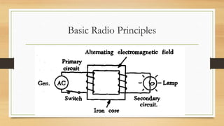
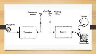
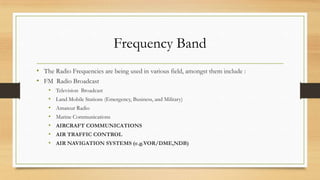
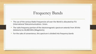
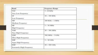
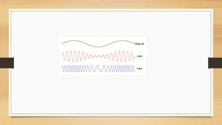
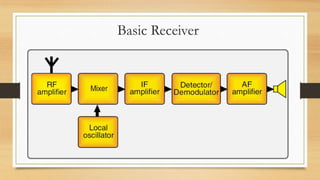
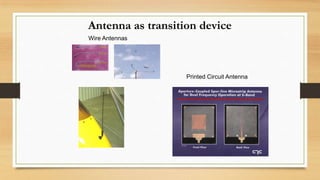
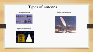
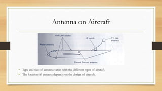
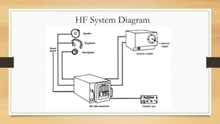
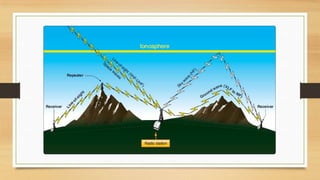


This document provides an overview of aircraft communication systems. It discusses the history of aircraft radio communication from World War I to modern times. It then describes the basic radio principles of transmission and reception using electromagnetic waves. It outlines the different frequency bands used for aircraft communication and navigation. It explains the main components and functions of transmitters and receivers. It also discusses different antenna types and their use on aircraft. Finally, it provides details on very high frequency (VHF) and high frequency (HF) communication systems, including system diagrams and their applications.


