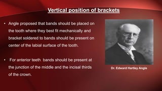
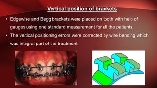
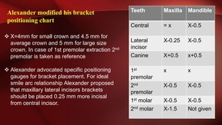
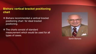
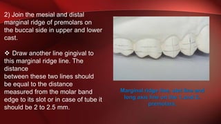
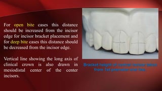
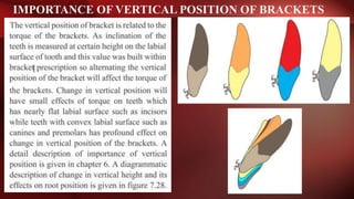
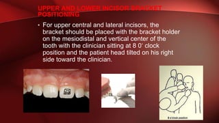
Supervision
Prof. Dr. Maher Fouda
Vertical position of brackets
From the time of bracket evolution till date,
orthodontists have much debated the vertical
position of the bracket but have failed to reach a
consensus to lay down a uniform protocol
• Angle proposed that bands should be placed on
the tooth where they best fit mechanically and
bracket soldered to bands should be present on
center of the labial surface of the tooth.
• For anterior teeth, bands should be present at
the junction of the middle and the incisal thirds
of the crown.
Vertical position of brackets
Dr. Edward Hartley Angle
• Edgewise and Begg brackets were placed on tooth with help of
gauges using one standard measurement for all the patients.
• The vertical positioning errors were corrected by wire bending which
was integral part of the treatment.
Vertical position of brackets
With the advent of straight wire Appliance, vertical
position of the bracket gained more importance. As
morphology of tooth is not uniform throughout its length
changing the vertical position of the bracket will result in
different expression of its builtin prescription.
Vertical position of brackets
Different guidelines for vertical position of the
brackets
Andrew Guidelines for bracket placement
1) It should be free of occlusal and
gingival interference.
2) The brackets siting site on a tooth
should have consistent angular
relationship with its occlusal plane and to
the occlusal plane of arch when all the
teeth are ideally placed.
3) When the teeth are ideally positioned, the middle of each bracket site must
be at the Andrew plane, where Andrew plane is a surface plane on which mid
transverse plane of every crown in an arch will fall when the teeth are optimally
positioned.
Andrew Guidelines for bracket placement
• In case gingival recession, Andrew quoted that
“1.8 mm should be subtracted from
anatomical crown to find the correct value of
clinical crown. This measurement must be
adjusted while placing bracket at FA point in
cases with gingival recession”.
• Andrew proposed that bracket must be
accurately placed within 2° of FACC and base
point or middle of the bracket should be within
0.5 mm of FA point.
Andrew Guidelines for bracket placement
• Where FA point (facial axis point) is
center of facial axis of clinical crown
(FACC) and it virtually divides the
clinical crown into occlusal half and
gingival half.
• The FACC on each tooth correspond
to mid-developmental ridge and in
case of molar it is dominant vertical
buccal groove.
Andrew Guidelines for bracket placement
Andrew also proposed using LA point (long axis point) for bracket
positioning, where LA point is the mid of long axis of clinical crown
(LACC).Though Andrew later disown LACC and LA point but amazingly
description of LACC or FACC remain the same in Andrew writings that was
mid developmental ridge and dominant vertical buccal groove in case of
molars.
Limitations of Andrew's Recommendations
• Placing brackets with only guessing the correct position will result in
vertical positioning errors. Not every orthodontist will place the bracket at
the same height. Even the same orthodontist, after accidental debonding
of bracket will rebond the bracket at a slightly different height
• Placing bracket is also troublesome in gingival recession and gingival
enlargement as vertical adjustment in bracket height in millimeters is again
a matter of guesswork.
• Also no consideration was given for incisal and occlusal edges
which are functional and esthetic units of teeth. Even an error of
0.5 mm in anterior teeth is noticed by esthetic conscious
patients.
• Eliades found out that positioning bracket at FA point results in
marginal ridge discrepancy and poor occlusal contacts.
Limitations of Andrew's Recommendations
Roth Guidelines
• Roth like Andrew also proposed
center of clinical crown for ideal
bracket placement to be used with
his prescription
• Roth advocated that for his
prescription anterior brackets should
be placed slightly more incisor than
Andrew proposed center of clinical
crown or FA point to level the curve
of spee.
Ronald H. Roth
• According to Roth the upper central and
lateral incisor should either be at the same
level or lateral incisor should be 0.5 mm less
prominent than central incisor.
• The central incisors will elongate 0.5 mm to
1mm more than the lateral incisor after
settling maxillary canine should be 1 to 1.5
mm below the occlusal plane while
mandibular canine should be 0.5 to 1 mm
above the occlusal plane.
•
• The upper and lower canines also should be
1mm more prominent than lateral incisors
and bicuspid.
Roth Guidelines
Most variation in bracket position are found in
bicuspids. In bicuspids the bracket should be
placed at area of maximum convexity which in
most cases is center of clinical crown.
In case of increase curve of spee the lower
canine brackets should be placed more occlusal
than the premolar brackets to avoid future wire
bending to level the curve of spee.
Roth Guidelines
• Roth recommendations are good to attain a
functional occlusion but merely guessing the
right height while placing brackets with such
accuracy in millimeters is usually not
possible
• According to Roth canine or premolar teeth
should be taken as reference while placing
brackets. A bracket positioning chart
advocated for speed brackets having Roth
prescription is given.
• No reference is found in literature whether
this chart is supported by Roth or it's just
manufacturer recommendation.
Limitations of Roth Guidelines
MandibleMaxillaTeeth
44Central
44Lateral
incisor
4.54.5Canine
4.54.51st
premolar
4.54.52nd
premolar
441st molar
43.52nd molar
Alexander Guidelines
• Alexander advocated individualizing
bracket positioning for each patient to
effectively use his bracket prescription.
• According to Alexander , the premolar
clinical crown height is the most
variable in the arch so premolar bracket
height (X) should be taken as
reference. All the other brackets are
placed with reference to premolar
bracket height (X). C. M. Alexander
Alexander Guidelines
• To find premolar bracket height,
premolar clinical crown height is taken
and is divided into half.
• The premolar normal bracket height
(X) is usually 4.5 mm. The chart for
bracket height measurement is given.
MandibleMaxillaTeeth
X-0.5= xCentral
X-0.5X-0.5Lateral
incisor
x+0.5X+0.5Canine
xx1st
premolar
xx2nd
premolar
X-0.5X-0.51st molar
Not givenX-12nd molar
Limitation of Alexander Guidelines
• Premolars in upper and lower arch were bonded at same height.
As 1st premolars cusps are longer than 2nd premolars especially
in lower arch so bonding all the premolar at the same height will
result in marginal ridges discrepancy and premature occlusal
contacts.
• Also no value was given for lower 2nd molars. To correct these
discrepancies , Alexander modified his bracket positioning chart.
Alexander modified his bracket
positioning chart
 X=4mm for small crown and 4.5 mm for
average crown and 5 mm for large size
crown. In case of 1st premolar extraction 2nd
premolar is taken as reference
 Alexander advocated specific positioning
gauges for bracket placement. For ideal
smile arc relationship Alexander proposed
that maxillary lateral incisors brackets
should be placed 0.25 mm more incisal
from central incisor.
MandibleMaxillaTeeth
X-0.5= xCentral
X-0.5X-0.25Lateral
incisor
x+0.5X+0.5Canine
xx1st
premolar
X-0.5X-0.52nd
premolar
X-0.5X-0.51st molar
Not givenX-1.52nd molar
Limitations of modified Alexander
Guidelines
• Alexander bracket positioning chart though
help to level incisor edges and give good
anterior aesthetics but taking premolar
clinical crown height as a reference mean
the clinician is denying all the variations in
other teeth clinical crown heights and
morphology.
• Taking half the height of clinical crowns in
premolars may result in marginal ridges
discrepancy and occlusal interferences.
• Wire bending is usually needed to
accommodate height differential and settle
down the occlusion
MandibleMaxillaTeeth
X-0.5= xCentral
X-0.5X-0.25Lateral
incisor
x+0.5X+0.5Canine
xx1st
premolar
X-0.5X-0.52nd
premolar
X-0.5X-0.51st molar
X-0.5X-1.52nd molar
 In modified chart the lateral incisor bracket
position was 0.25 mm more incisal than
central incisor. It is extremely difficult to
place bracket with 0.25 mm accuracy even
with the help of gauge because of the play
between slot supporting part of the gauge
and slot of the bracket.
 In modified Alexander bracket positioning
chart upper 2nd molar height is 1 mm greater
than 1st molar, this can create marginal r
idge idge discrepancy between the maxillary
molars in many cases
Limitations of modified Alexander Guidelines
MandibleMaxillaTeeth
X-0.5= xCentral
X-0.5X-0.25Lateral
incisor
x+0.5X+0.5Canine
xx1st
premolar
X-0.5X-0.52nd
premolar
X-0.5X-0.51st molar
X-0.5X-1.52nd molar
Bishara vertical bracket positioning
chart
 Bishara recommended a vertical bracket
positioning chart for ideal bracket
positioning.
 The charts consist of standard
measurement which would be used for all
types of cases.
Samir Bishara
Bishara vertical bracket positioning
chart
Bracket positioning gauges are
used to place the brackets.
Placing brackets from fixed
distance from incisors and
occlusal edges will give good
anterior aesthetics.
Mandible
maxilla
Teeth
3.54Central
incisor
3.53.5Lateral
incisor
4.54.5Canine
44Premolars
and molar
Limitations of Bishara vertical bracket positioning
• As the method contains a standard chart for all types of cases so it
fails to address individual variations. Also it's a matter of common
clinical experience that molars cusps are smaller than premolars.
Placing brackets at the same height will result poor marginal ridge
relations and opposing occlusal interferences.
• Gu ZX found that to level marginal ridges 2nd premolar bracket
height should be 0.5 mm greater than 1st molar and 1st premolar
bracket height should be at least 0.5 mm greater than 2nd premolar
so using Bishara chart will leave marginal ridge discrepancy.
McLaughlin or MBT vertical bracket
positioning
The method is given as follow:
1) Measure the clinical crown height of fully
erupted teeth on the upper and lower study
cast by dividers and millimeter rulers.
2) To obtain middle of clinical crown divide
the measured height of each crown into half
and round the obtained value to the nearest
0.5mm.For example if crown height is
10.75mm.Half the crown height would be
5.4 mm. Make this measurement to 5.5 mm
3) Create separate rows of measurements
for maxillary and mandibular teeth. Now
compare your values of maxillary and
mandibular teeth with that of proposed
charts. If your chart measurement don't
exactly tally with that of proposed MBT
charts then find a row on the chart which
matches most of your recorded
measurement .
McLaughlin or MBT vertical bracket
positioning
2nd molar1st molar2nd
premolar
1st
premolar
CanineLateralCentral
2455.565.56
23.54.555.555.5
2344.554.55
22.53.544.544.5
2233.543.54
McLaughlin or MBT vertical bracket positioning
Maxillary Arch (mm)
2nd molar1st molar2nd
premolar
1st
premolar
CanineLateralCentral
3.53.54.555.555
3344.554.54.5
2.52.53.544.544
2233.543,53.5
222.533.533
Mandibular Arch (mm)
McLaughlin or MBT vertical bracket positioning
2nd
molar
1st
molar
2nd
premolar
1st
premolar
Caninelateralcentral
2344.554.55
2.52.53.544.544
2nd
molar
1st
molar
2nd
premolar
1st
premolar
CaninelateralCentral
22.53.544.544.5
2233.543.53.5
Average values for bracket positioning chart in adults
Average values for bracket positioning chart in children
Limitations of McLaughlin or MBT vertical
bracket positioning chart
Due to individual variation of cusps height
in premolar region marginal ridges height
difference is seen in finished cases as posterior
bracketing is not optimum17 to level marginal
ridges.
Kalange method
• Kalange devised a practical method to level the
marginal ridges by bracket placement .
• Kalange though favors indirect bonding but his
technique of bracket positioning can be used in
direct bonding too.
Kalange method of ideal bracket
placement has the following steps.
1) Select a snugly fit 1st molar band in both
arches. Measure the distance from occlusal
edge of molar band to its slot.
In case tubes are placed on the molars instead
of bands then draw a line on the buccal side of
molars connecting its mesial and distal
marginal ridges. The slot of the tube lies 2 to
2.5 mm below molar marginal ridge line. The
lines are drawn on dental cast in case of
indirect bonding or on the natural teeth in case
of direct bonding with a thin pencil.
Horizontal lines drawn on the molars.
Lower line is the marginal ridge line while the
upper line is slot line for molar tube.
2) Join the mesial and distal
marginal ridge of premolars on
the buccal side in upper and lower
cast.
 Draw another line gingival to
this marginal ridge line. The
distance
between these two lines should
be equal to the distance
measured from the molar band
edge to its slot or in case of tube it
should be 2 to 2.5 mm.
Marginal ridge line, slot line and
long axis line on the 1st and 2nd
premolars.
• This second gingival line is called the
slot line.
• The bracket slot of premolar brackets
should be coinciding with this slot line.
• Mark a line in the mesiodistal center of
the tooth following long axis of clinical
crown.
• The wings and scribe line of the
brackets should be parallel to this line
for axial correction of bracket Marginal ridge line, slot line and
long axis line on the 1st and 2nd
premolars.
3) Measure the distance from cusp tip of
premolars, ideally from 1st premolars in both
arches and transfer it to respective arch
central incisors taking the incisor edge as
reference point. So the slot line of premolars
and central incisor are at same distance
from cusp tips or incisor edges.
This distance should ideally be 4 mm
for mandibular incisors and 4.5 mm for
maxillary incisors .
For open bite cases this distance
should be increased from the incisor
edge for incisor bracket placement and
for deep bite cases this distance should
be decreased from the incisor edge.
Vertical line showing the long axis of
clinical crown is also drawn in
mesiodistal center of the center
incisors.
Bracket height of central incisor taken
from 1st premolar slot line.
4) The maxillary lateral incisors slot
line should be decreased by 0.5 mm
from the incisor edge while for
mandibular lateral incisor slot line
distance should be same as central
incisors (Figure 7.23).
5) The maxillary and mandibular canines
slot line distance should be 1 mm more
from their respective central incisor slot
lines. In case of canines the canine tip
should be taken as reference
6) Vertical lines are also drawn on all the
teeth to mark the mesiodistal middle of
the crown.
Canine bracket slot line measured and
drawn on the tooth.
Limitations of Kalange method
• Kalange method is good to level marginal ridges and give
good anterior aesthetic by placing anterior tooth edges at
optimum level
• But this method ignores individual variation in crown
height of anterior teeth. Placing anterior brackets too
incisal or gingival will result in different torque expression
than builtin bracket torque due to morphological variations
of the teeth.
• In using Kalange method of
bracket positioning for direct
bonding lines are drawn by pencil
on the teeth.
• Some clinicians point out that
these pencil lines on the teeth will
interfere with bond strength. To
contour this problem slot line and
vertical line should not cross the
final bracket sitting area.
• Even if these lines don't cross the
bracket sitting area they give a
realistic guidance for correct
orientation of brackets.
Lines drawn on the labial surface of the teeth
can give good indication of bracket orientation
without passing through the bracket sitting area.
Limitations of Kalange method
Selecting the height from molar
band edge to slot can also result in
vertical positioning errors.
Most of the companies make molar bands
with occlusal proximal edges which lie
next to marginal ridges more gingival
than buccal and lingual edges. This is
variation is more pronounced in upper
arch.
Figure 7.26).
The proximal edges of the band which
correspond to the molar marginal ridge
are usually at different height than their
buccal counterparts
Limitations of Kalange method
The proximal edges of the band must be in level
with the marginal ridges so distance from buccal
edge will result in faulty bracket positioning.
Either height difference between buccal and
proximal edges should be accommodated in final
calculation or it is a better option to draw
marginal ridge line and slot line on molars too
even a band is to be placed on molars .
The proximal edges of the band which
correspond to the molar marginal ridge
are usually at different height than their
buccal counterparts
Limitations of Kalange method
Modified Kalange Method
• A modified method is devised in which molar and premolar
brackets are bonded with respect to marginal ridges and instead
of transferring 1st premolar height to central it transferred to
lateral incisor in maxillary arch.
• A MBT advocated gauge is used to transfer closet height from
1st premolar to lateral incisor. Central incisor and canines are
bonded at same height. In lower arch 1st premolar height is
transferred to both central and lateral incisors and canine tip are
kept 0.5 mm more prominent.
PLACEMENT OF ORTHODONTIC BRACKETS
• Vertical position of brackets
 Viazis guidelines
• Modifications in Vertical position of the brackets
• Importance of vertical position of brackets
VIAZIS GUIDELINES FOR BRACKET
PLACEMENT.
 Central incisors brackets are
taken as reference.
 maxillary central incisor bracket
(X)
 mandibular central incisor
bracket (Y)
 Both of them (x)(y) placed at FA
point which is center of clinical
crown.
VIAZIS GUIDELINES FOR BRACKET
PLACEMENT.
• The distance from the incisor edge
to FA point is measured. Rest of
the brackets are placed with
reference to these brackets at
proposed distance (Table 7.9) with
the help of bracket positioning
gauges.
MODIFICATIONS IN VERTICAL POSITION OF THE
BRACKETS
Bracket placement needed recommended alteration under certain
situations as in :
1. Open bite .
2. deep bite .
3. Irregular incisors edges.
4. Long canine tip .
5. Attrition of canine .
6. High buccally placed teeth .
7. Gingival recession .
8. Premolar extraction .
it is a critical in determining
what to do.
1-OPEN BITE :
This is done by placing the brackets more
gingival on the tooth which are in open
bite. In most case of open bite, only
maxillary anterior teeth are contributing to
open bite and so bracket position alteration
should be done in maxillary arch only.
But if mandibular arch has a reverse curve
of spee then bracket position alteration
should also be done in mandibular arch too.
1-OPEN BITE :
The Clinician advocate different rule for
bracket placement during treatment of open
bite:
Alexander proposed that the teeth which
are in open bite should be bonded .5 mm
more gingival while teeth in occlusion
should be .5 mm more occlusal .
MBT proposed that teeth which are in open
bite should be bonded .5 mm more gingival
than their prescribed position, and the rests
of brackets are bonded at their normal
height.
1-OPEN BITE :
Case Example 2 /
A n adult patient with skeletal open
bite. The case was to be treated non
extraction and surgically by differential
maxillary impaction and mandibular
setback.
No alteration in bracket position was
done but mechanics were changed.
In lower arch continuous arch wire
was used while in maxillary arch wire
bending was used to divide upper arch
into 3 segments. Canine to canine and
premolars to 2 molars on both sides.
In surgical cases no dental camouflage
of open bite is done by varying the
bracket position
1-OPEN BITE :
Case Example 3 :
An open bite case treated with upper
1st and lower 2nd premolar
extraction. In this case the upper
incisor were composite build up and
all the brackets from 2nd premolar in
upper and 1st premolar lower arch
were bonded 0.5mm more gingival,
while the 1 and 2 molar tube were
bonded 0.5 mm more occlusal in
accordance with Alexander guidelines.
If one follow McLaughlin guidelines
molars would be bonded according to
chart values while all other teeth
would be bonded 0.5 mm more
gingival.
2-DEEP BITE
In deep bite cases the rules of bonding brackets are
opposite that of open bite cases.
2-DEEP BITE :
In MBT system teeth which are in deep bite are bonded 0.5mm
more incisal while in Alexander discipline teeth which are in
deep bite are bonded 0.5 mm more incisal while other teeth are
bonded 0.5 mm more gingival
2-DEEP BITE :
Case example
A patient with class II div 2 having deep bite. The
case was planned with:
 extraction of upper 1stpremolars.
 initially only upper arch was bonded.
 instead of raising the bite maxillary incisors were initially
proclined to attain their normal inclination.
 By using MBT system chart Brackets on maxillary six
anterior teeth were bonded 0.5mm more incisal than
their advocated position .
 lower anterior six brackets were also bonded 0.5 mm
more incisal .
 All posterior brackets in both maxillary and mandibular
arches were bonded at their recommended height.
3-IRREGULAR INCISORS EDGES
Clinician suggest 3 options
for manage long cusp tip and
irregular edges :
1. Recontouring of the incisor
edges or cusp tips before
bracket placement.
2. Recontouring of the incisor
edges or cusp tips at end of
treatment.
3. Composite filling of the incisor
edges and cusp tips.
Recontouring
before or after
bracket
placement ??!!
3-IRREGULAR INCISORS EDGES
Ideally teeth should be recontoured
previous to bracket placement.
If teeth are recontoured previous to
orthodontic treatment so there is no
need to alter the bracket height.
But if it is planned to recontour at the
end of orthodontic treatment or
composite
filling is needed at the end of
treatment , then height modification of
bracket is done at the start of
treatment.
3-IRREGULAR INCISORS EDGES
Case example
A young patient presented with class II
div 1 was treated with twin block and fixed
braces. Incisor edges were irregular at
the start of treatment
 Brackets were bonded according to
MBT charts but upper incisors were
bonded 0.5mm more gingival.
 If the final overbite result are doubtful
,its better to leave incisal edge and
then will reshaped at the end of
treatment .
 at the end if this case have open bite or
minimal overbite the clinician have
been gone for composit build up to
the overbite .
Before After
3-IRREGULAR INCISORS EDGES
A young female beginning her orthodontic
treatment had central incisors with
numerous esthetic deficiencies:
1. Square shape: height to width ratios of
about 1:1 .
2. Greater width in the contact area than at the
incisal edge (inverted taper)
Case 2 /
3-IRREGULAR INCISORS EDGES
• 3. Excessive incisal embrasures
result in apically positioned,
relatively narrow contact areas:
connector <50%
4. Prominent mesial and distal
marginal ridges on the labial surface
(double shoveling)
5. IRREGULAR INCISAL EDGES
• 5. Irregular incisal edges
• Step 1
1- Only well aligned teeth are good
candidates for enameloplasty.
(investigate by x-ray )
2-Reshaping malposed teeth is not
recommended because it is difficult to
visualize the appropriate tooth shape
that will result in a desired final
alignment .
• Step 2: inter poroximal
reduction (IPR) .
5. IRREGULAR INCISAL EDGES
Enameloplasty Step By Step
The enamel reduction should be no
more than 0.5mm (0.25mm each side)
per tooth. yellow lines are references
for the axial inclination and width of
each labial surface .
Step 3:
Prominent marginal ridges
(double shoveling) were smoothed
with a flat-end high speed diamond
bur, and then the adjusted surface
was polished with a white stone
Step 4:
The incisor edges were smoothed
with a sandpaper disk
5. IRREGULAR INCISAL EDGES
Result Achieved
5. IRREGULAR INCISAL EDGES
The width to height ratio was about 0.8, and the
connector length between central incisors was
increased to the ideal of ~50%.
the labial surface of the central incisors
was smooth after marginal ridge
recontouring, but the palatal contours
required more reduction to avoid
interfering with the overbite, overjet
and interproximal alignment.
4-LONG CANINE TIP
In cases where canine tip is long, it's better
to place brackets 0.5mm more gingival
than standard values and reshape canine
tips at the end of treatment.
Another option is :
to reshape canine tip at the start of the
treatment and place bracket at its ideal
position. Long canine tips are usually
found in impacted canines or canine
placed out of occlusion.
buccally placed canine
lack of function and attrition
5. ATTRITION OF THE CANINE
In case of attrition of the canine the
brackets are placed 0.5-1 mm more
gingival, depending upon the severity of
attrition. The canine tip is reshaped at the
end of treatment.
6. HIGH BUCCALLY PLACED TEETH
7. GINGIVAL RECESSION
Individual teeth with up to 1.5mm gingival
recession can be bonded more gingival so
that at end of treatment their gingival
margins should be at the ideal height. But
incisor or occlusal edge needed to be
reshaped by equal amount.
In teeth with more than 1.5 mm of gingival
recession an expert opinion from periodontist
should be taken and many a time gingival
grafting is a viable option than bracket
position alteration.
8. PREMOLAR EXTRACTION CASES
IMPORTANCE OF VERTICAL POSITION OF BRACKETS
 BRACKET POSITIONING GAUGES
• Bracket positioning gauges
are used to ensure vertical
accuracy of brackets on the
teeth. Many different
instruments have been
recommended to check for
vertical accuracy of seated
brackets ranging from
periodontal probes to rulers
but.
• In contemporary
orthodontics two types of
gauges or their variations
are usually used. These
are:
1. Star shaped gauges or
Boone bracket gauges.
A Boone gauge
2. Straight rod shaped gauges or Dougherty
gauges.
Straight rod shaped gauges similar
to Alexander Wick stick for 0.22” and
0.018” slot.
 PARTS OF GAUGES
• All bracket positioning gauges have a holding
arm for holding the gauge with fingers during
bracket positioning, a tooth supporting arm
which rest on the incisor or occlusal surface of
the tooth and a slot supporting arm which is
seated in slot of the bracket.
PARTS OF GAUGES
• The holding arm is the longest part of gauges
while the slot supporting arm is the shortest part
of the gauges. Different slot supporting arms are
available for 0.018” and 0.022” slots.
 POSITION OF THE GAUGE DURING BRACKET
PLACEMENT
• Positioning the gauge for checking the vertical height is very
important. In an unpublished study it found out that a faulty
positioning of gauge can change bracket height up to 2mm.
• Varying the angle the gauge over tooth can change the
height of the bracket which is usually in the range of 2mm.
As the angle between the gauge and tooth decrease height
of the bracket on the tooth increases.
• As explained before variation in position of the bracket will result
in change in torque expression. Also variation of 2mm in brackets
height in anterior dentition has serious implication in terms of
anterior aesthetic and smile arc.
POSITION OF THE GAUGE DURING BRACKET
PLACEMENT
• For correct positioning the gauge should be held in hand at right
angle so that the orthodontist vision should also be at right angel to
the gauge. The gauge should always be placed perpendicular to
the labial or buccal surface of the teeth.
• This makes the gauges parallel to the occlusal surface in all the
teeth except incisors In lower arch if the incisors are upright the
gauge should be placed parallel to the occlusal plane.
• But if the lower incisors
are proclined the gauge
is placed below the
occlusal plane and if the
lower incisors are
retroclined the gauge is
directed from above the
occlusal plane.
• In case of upper
incisors the gauge is
placed slightly upward
angulated usually 15°
to 20° to the occlusal
plane to make it
perpendicular to the
labial surface of the
tooth as the upper
incisor are slightly
inclined forward over
basal bone.
• In case class II div 1 incisor relationship where the
upper incisors are proclined the gauge is
angulated more upward as compared to normal
incisor inclination.
• In case of class II div 2 the gauge lies below the
occlusal plane angulated at an angle depending
upon the severity of malocclusion.
 BRACKET PLACEMENT BY WIRE
GUIDANCE
• In this technique all the steps of conventional
bonding are done in usual way but before curing
the bracket a heavy wire is passed through the
bracket slot and its bonded neighboring brackets
and bands. The mesiodistal position of the
bracket is corrected manually while axial and
vertical positions are guided by the heavy wire.
 BRACKET PLACEMENT BY WIRE GUIDANCE
• Orthodontic brackets can be placed by wire guidance if brackets are debonded
when 0.016x0.022 inch or heavier wire is in place. If brackets are placed in usual
way then due to small human errors, mostly it is not possible to place the existing
working wire after bracket rebonding and clinician need to move back on lighter
wires.
 BRACKET PLACEMENT BY WIRE GUIDANCE
• Brackets can also be placed on wire guidance from the start of
treatment if clinician does not want to change the angulation of teeth
and want to do some specific mechanics without any time delay. Such
scenario is usually found in cases of impacted teeth where neighboring
teeth roots are close to impacted teeth and any delay may result in
increased risk of root resorption from impacted teeth.
 BRACKET PLACEMENT BY WIRE GUIDANCE
• Placing brackets on wire guidance is also helpful in adjunctive orthodontics when
only one tooth need up righting to create space for future prosthesis. In such
cases a heavy wire is selected and all the brackets are placed on its guidance
while the tooth needing uprighting is bonded in normal way without wire guidance.
 POSITION OF CLINICIAN DURING BRACKETS
PLACEMENT
• It is generally said that while
placing brackets orthodontist
should maintain a single
position at which he can see
the teeth at right angle. Also
the head of the patient
should not be moved again
and again as this is not
comfortable for the patient.
• Before placing the brackets the position of the dental unit should
be properly adjusted.
• Usually a dental unit is adjusted between 140° to 150. At this
position the clinician can easily see the brackets at right angle.
• This setting also helps to see axial position of some brackets from 12
o' clock position. The clinician position for bracket placement given
here are for right handed orthodontist. For left handed orthodontist
similar positions would be used from the left side.
UPPER AND LOWER INCISOR BRACKET
POSITIONING
• For upper central and lateral incisors, the
bracket should be placed with the bracket holder
on the mesiodistal and vertical center of the
tooth with the clinician sitting at 8 0‘ clock
position and the patient head tilted on his right
side toward the clinician.
• After the bracket is
placed, the height of
the bracket is checked
with bracket positioner.
The patient head is
mad straight and
orthodontist check it
from 9 o'clock
positions with the
gauge at right angle to
his vision.
• To check the mesiodistal and axial position of the
bracket the orthodontist moves to 12 o‘ clock
position and place a diagnostic mouth mirror at
the incisor edge to indirectly check the
mesiodistal position of the bracket.
• This indirect vision also help to correct the axial or long axis position of the
bracket to some extent but direct vision will give an excellent picture
whether the wings of the bracket and the bracket scribe line is parallel to
long axis of clinical crown. While checking axial inclination of maxillary
lateral incisors brackets it is a good practice to tilt the head of the patient to
opposite side. For right maxillary lateral the patient head should be tilted
toward left side and versa.
• The lower incisors brackets are placed in a
similar fashion as upper incisors brackets.
Vertical height is checked from 9 o' clock
position while 12 o'clock position is used to
check to mesiodistal and axial position of
brackets.
• Diagnostic mouth mirror can be placed gingival to the bracket to
check mesiodistal position of the bracket. Some clinician prefer to
check mesiodistal and axial position of lower incisor bracket from 8
o‘ clock position under direct vision with patients head tilted towards
the orthodontist.
UPPER AND LOWER CANINES
• Positioning of right upper and lower canines brackets is done at 9
o' clock position with the mesiodistal and axial placement checked
from the same position while the vertical height of the bracket is
checked with gauge from 11 o‘clock position.
9 o’clock position
11 o’clock position
UPPER AND LOWER CANINES
• For left side upper and lower canines the
brackets are placed from 9 o' clock position with
the patient head tilted toward right. The
mesiodistal and axial positions of brackets are
checked under direct vision from the same 9
o'clock position.
9 o’clock position
UPPER AND LOWER BICUSPIDS
• Upper right bicuspids brackets are placed at 9 o' clock positions and its
vertical height is checked with gauge from 11 o' clock position with
patients head slightly tilted toward left Many a time the cheek retractor
hinders the correct positioning of the bracket positioning gauge.
9 o’clock position 11 o’clock position
UPPER AND LOWER BICUSPIDS
• Check the mesiodistal position of the bracket from 11 or 12 o' clock
position with diagnostic mirror using indirect vision. This vision also
gives some hint about axial position of the bracket but the correct
axial position is checked from 9 o' clock position under direct vision
with patient head tilted toward left.
UPPER AND LOWER BICUSPIDS
• Right lower bicuspids brackets are placed on the tooth at 9
o'clock position. The vertical height is checked and adjusted
from 11o'clock position.
9 o’clock position
UPPER AND LOWER BICUSPIDS
• The clinician check axial and mesiodistal position of the bracket at 10
o'clock position under direct vision. Some clinician can recheck the
mesiodistal position of the bracket under indirect vision by placing
diagnostic mirror on occlusal surface of bracket.
UPPER AND LOWER BICUSPIDS
• Upper left bicuspids are placed at 9 o' clock position with the patient
head tilted toward right. The mesiodistal position is checked under
indirect vision with diagnostic mirror from 12 o' clock with the patient
head tilted toward right.
9 o’clock position
UPPER AND LOWER BICUSPIDS
• The 12 o'clock position also give a good view for axial position of
bracket under indirect vision but it's better to see axial position of
bracket from 8 o'clock position under direct vision with the patients
head tilted toward right.
UPPER AND LOWER BICUSPIDS
• Lower left bicuspid brackets are placed from 9 o'clock positions with
the patient head tilted toward right. The mesiodistal and axial
position of the brackets are confirmed at 8 o'clock position under
direct vision.
9 o’clock position
Bracket positioning

Bracket positioning

  • 1.
  • 3.
    Vertical position ofbrackets From the time of bracket evolution till date, orthodontists have much debated the vertical position of the bracket but have failed to reach a consensus to lay down a uniform protocol
  • 4.
    • Angle proposedthat bands should be placed on the tooth where they best fit mechanically and bracket soldered to bands should be present on center of the labial surface of the tooth. • For anterior teeth, bands should be present at the junction of the middle and the incisal thirds of the crown. Vertical position of brackets Dr. Edward Hartley Angle
  • 5.
    • Edgewise andBegg brackets were placed on tooth with help of gauges using one standard measurement for all the patients. • The vertical positioning errors were corrected by wire bending which was integral part of the treatment. Vertical position of brackets
  • 7.
    With the adventof straight wire Appliance, vertical position of the bracket gained more importance. As morphology of tooth is not uniform throughout its length changing the vertical position of the bracket will result in different expression of its builtin prescription. Vertical position of brackets
  • 8.
    Different guidelines forvertical position of the brackets Andrew Guidelines for bracket placement 1) It should be free of occlusal and gingival interference. 2) The brackets siting site on a tooth should have consistent angular relationship with its occlusal plane and to the occlusal plane of arch when all the teeth are ideally placed.
  • 9.
    3) When theteeth are ideally positioned, the middle of each bracket site must be at the Andrew plane, where Andrew plane is a surface plane on which mid transverse plane of every crown in an arch will fall when the teeth are optimally positioned. Andrew Guidelines for bracket placement
  • 10.
    • In casegingival recession, Andrew quoted that “1.8 mm should be subtracted from anatomical crown to find the correct value of clinical crown. This measurement must be adjusted while placing bracket at FA point in cases with gingival recession”. • Andrew proposed that bracket must be accurately placed within 2° of FACC and base point or middle of the bracket should be within 0.5 mm of FA point. Andrew Guidelines for bracket placement
  • 11.
    • Where FApoint (facial axis point) is center of facial axis of clinical crown (FACC) and it virtually divides the clinical crown into occlusal half and gingival half. • The FACC on each tooth correspond to mid-developmental ridge and in case of molar it is dominant vertical buccal groove. Andrew Guidelines for bracket placement
  • 12.
    Andrew also proposedusing LA point (long axis point) for bracket positioning, where LA point is the mid of long axis of clinical crown (LACC).Though Andrew later disown LACC and LA point but amazingly description of LACC or FACC remain the same in Andrew writings that was mid developmental ridge and dominant vertical buccal groove in case of molars.
  • 13.
    Limitations of Andrew'sRecommendations • Placing brackets with only guessing the correct position will result in vertical positioning errors. Not every orthodontist will place the bracket at the same height. Even the same orthodontist, after accidental debonding of bracket will rebond the bracket at a slightly different height • Placing bracket is also troublesome in gingival recession and gingival enlargement as vertical adjustment in bracket height in millimeters is again a matter of guesswork.
  • 14.
    • Also noconsideration was given for incisal and occlusal edges which are functional and esthetic units of teeth. Even an error of 0.5 mm in anterior teeth is noticed by esthetic conscious patients. • Eliades found out that positioning bracket at FA point results in marginal ridge discrepancy and poor occlusal contacts. Limitations of Andrew's Recommendations
  • 15.
    Roth Guidelines • Rothlike Andrew also proposed center of clinical crown for ideal bracket placement to be used with his prescription • Roth advocated that for his prescription anterior brackets should be placed slightly more incisor than Andrew proposed center of clinical crown or FA point to level the curve of spee. Ronald H. Roth
  • 16.
    • According toRoth the upper central and lateral incisor should either be at the same level or lateral incisor should be 0.5 mm less prominent than central incisor. • The central incisors will elongate 0.5 mm to 1mm more than the lateral incisor after settling maxillary canine should be 1 to 1.5 mm below the occlusal plane while mandibular canine should be 0.5 to 1 mm above the occlusal plane. • • The upper and lower canines also should be 1mm more prominent than lateral incisors and bicuspid. Roth Guidelines
  • 17.
    Most variation inbracket position are found in bicuspids. In bicuspids the bracket should be placed at area of maximum convexity which in most cases is center of clinical crown. In case of increase curve of spee the lower canine brackets should be placed more occlusal than the premolar brackets to avoid future wire bending to level the curve of spee. Roth Guidelines
  • 18.
    • Roth recommendationsare good to attain a functional occlusion but merely guessing the right height while placing brackets with such accuracy in millimeters is usually not possible • According to Roth canine or premolar teeth should be taken as reference while placing brackets. A bracket positioning chart advocated for speed brackets having Roth prescription is given. • No reference is found in literature whether this chart is supported by Roth or it's just manufacturer recommendation. Limitations of Roth Guidelines MandibleMaxillaTeeth 44Central 44Lateral incisor 4.54.5Canine 4.54.51st premolar 4.54.52nd premolar 441st molar 43.52nd molar
  • 19.
    Alexander Guidelines • Alexanderadvocated individualizing bracket positioning for each patient to effectively use his bracket prescription. • According to Alexander , the premolar clinical crown height is the most variable in the arch so premolar bracket height (X) should be taken as reference. All the other brackets are placed with reference to premolar bracket height (X). C. M. Alexander
  • 20.
    Alexander Guidelines • Tofind premolar bracket height, premolar clinical crown height is taken and is divided into half. • The premolar normal bracket height (X) is usually 4.5 mm. The chart for bracket height measurement is given. MandibleMaxillaTeeth X-0.5= xCentral X-0.5X-0.5Lateral incisor x+0.5X+0.5Canine xx1st premolar xx2nd premolar X-0.5X-0.51st molar Not givenX-12nd molar
  • 21.
    Limitation of AlexanderGuidelines • Premolars in upper and lower arch were bonded at same height. As 1st premolars cusps are longer than 2nd premolars especially in lower arch so bonding all the premolar at the same height will result in marginal ridges discrepancy and premature occlusal contacts. • Also no value was given for lower 2nd molars. To correct these discrepancies , Alexander modified his bracket positioning chart.
  • 22.
    Alexander modified hisbracket positioning chart  X=4mm for small crown and 4.5 mm for average crown and 5 mm for large size crown. In case of 1st premolar extraction 2nd premolar is taken as reference  Alexander advocated specific positioning gauges for bracket placement. For ideal smile arc relationship Alexander proposed that maxillary lateral incisors brackets should be placed 0.25 mm more incisal from central incisor. MandibleMaxillaTeeth X-0.5= xCentral X-0.5X-0.25Lateral incisor x+0.5X+0.5Canine xx1st premolar X-0.5X-0.52nd premolar X-0.5X-0.51st molar Not givenX-1.52nd molar
  • 23.
    Limitations of modifiedAlexander Guidelines • Alexander bracket positioning chart though help to level incisor edges and give good anterior aesthetics but taking premolar clinical crown height as a reference mean the clinician is denying all the variations in other teeth clinical crown heights and morphology. • Taking half the height of clinical crowns in premolars may result in marginal ridges discrepancy and occlusal interferences. • Wire bending is usually needed to accommodate height differential and settle down the occlusion MandibleMaxillaTeeth X-0.5= xCentral X-0.5X-0.25Lateral incisor x+0.5X+0.5Canine xx1st premolar X-0.5X-0.52nd premolar X-0.5X-0.51st molar X-0.5X-1.52nd molar
  • 24.
     In modifiedchart the lateral incisor bracket position was 0.25 mm more incisal than central incisor. It is extremely difficult to place bracket with 0.25 mm accuracy even with the help of gauge because of the play between slot supporting part of the gauge and slot of the bracket.  In modified Alexander bracket positioning chart upper 2nd molar height is 1 mm greater than 1st molar, this can create marginal r idge idge discrepancy between the maxillary molars in many cases Limitations of modified Alexander Guidelines MandibleMaxillaTeeth X-0.5= xCentral X-0.5X-0.25Lateral incisor x+0.5X+0.5Canine xx1st premolar X-0.5X-0.52nd premolar X-0.5X-0.51st molar X-0.5X-1.52nd molar
  • 25.
    Bishara vertical bracketpositioning chart  Bishara recommended a vertical bracket positioning chart for ideal bracket positioning.  The charts consist of standard measurement which would be used for all types of cases. Samir Bishara
  • 26.
    Bishara vertical bracketpositioning chart Bracket positioning gauges are used to place the brackets. Placing brackets from fixed distance from incisors and occlusal edges will give good anterior aesthetics. Mandible maxilla Teeth 3.54Central incisor 3.53.5Lateral incisor 4.54.5Canine 44Premolars and molar
  • 27.
    Limitations of Bisharavertical bracket positioning • As the method contains a standard chart for all types of cases so it fails to address individual variations. Also it's a matter of common clinical experience that molars cusps are smaller than premolars. Placing brackets at the same height will result poor marginal ridge relations and opposing occlusal interferences. • Gu ZX found that to level marginal ridges 2nd premolar bracket height should be 0.5 mm greater than 1st molar and 1st premolar bracket height should be at least 0.5 mm greater than 2nd premolar so using Bishara chart will leave marginal ridge discrepancy.
  • 28.
    McLaughlin or MBTvertical bracket positioning The method is given as follow: 1) Measure the clinical crown height of fully erupted teeth on the upper and lower study cast by dividers and millimeter rulers. 2) To obtain middle of clinical crown divide the measured height of each crown into half and round the obtained value to the nearest 0.5mm.For example if crown height is 10.75mm.Half the crown height would be 5.4 mm. Make this measurement to 5.5 mm
  • 29.
    3) Create separaterows of measurements for maxillary and mandibular teeth. Now compare your values of maxillary and mandibular teeth with that of proposed charts. If your chart measurement don't exactly tally with that of proposed MBT charts then find a row on the chart which matches most of your recorded measurement . McLaughlin or MBT vertical bracket positioning
  • 30.
  • 31.
  • 32.
  • 33.
    Limitations of McLaughlinor MBT vertical bracket positioning chart Due to individual variation of cusps height in premolar region marginal ridges height difference is seen in finished cases as posterior bracketing is not optimum17 to level marginal ridges.
  • 34.
    Kalange method • Kalangedevised a practical method to level the marginal ridges by bracket placement . • Kalange though favors indirect bonding but his technique of bracket positioning can be used in direct bonding too.
  • 35.
    Kalange method ofideal bracket placement has the following steps. 1) Select a snugly fit 1st molar band in both arches. Measure the distance from occlusal edge of molar band to its slot. In case tubes are placed on the molars instead of bands then draw a line on the buccal side of molars connecting its mesial and distal marginal ridges. The slot of the tube lies 2 to 2.5 mm below molar marginal ridge line. The lines are drawn on dental cast in case of indirect bonding or on the natural teeth in case of direct bonding with a thin pencil. Horizontal lines drawn on the molars. Lower line is the marginal ridge line while the upper line is slot line for molar tube.
  • 36.
    2) Join themesial and distal marginal ridge of premolars on the buccal side in upper and lower cast.  Draw another line gingival to this marginal ridge line. The distance between these two lines should be equal to the distance measured from the molar band edge to its slot or in case of tube it should be 2 to 2.5 mm. Marginal ridge line, slot line and long axis line on the 1st and 2nd premolars.
  • 37.
    • This secondgingival line is called the slot line. • The bracket slot of premolar brackets should be coinciding with this slot line. • Mark a line in the mesiodistal center of the tooth following long axis of clinical crown. • The wings and scribe line of the brackets should be parallel to this line for axial correction of bracket Marginal ridge line, slot line and long axis line on the 1st and 2nd premolars.
  • 38.
    3) Measure thedistance from cusp tip of premolars, ideally from 1st premolars in both arches and transfer it to respective arch central incisors taking the incisor edge as reference point. So the slot line of premolars and central incisor are at same distance from cusp tips or incisor edges. This distance should ideally be 4 mm for mandibular incisors and 4.5 mm for maxillary incisors .
  • 39.
    For open bitecases this distance should be increased from the incisor edge for incisor bracket placement and for deep bite cases this distance should be decreased from the incisor edge. Vertical line showing the long axis of clinical crown is also drawn in mesiodistal center of the center incisors. Bracket height of central incisor taken from 1st premolar slot line.
  • 40.
    4) The maxillarylateral incisors slot line should be decreased by 0.5 mm from the incisor edge while for mandibular lateral incisor slot line distance should be same as central incisors (Figure 7.23).
  • 41.
    5) The maxillaryand mandibular canines slot line distance should be 1 mm more from their respective central incisor slot lines. In case of canines the canine tip should be taken as reference 6) Vertical lines are also drawn on all the teeth to mark the mesiodistal middle of the crown. Canine bracket slot line measured and drawn on the tooth.
  • 42.
    Limitations of Kalangemethod • Kalange method is good to level marginal ridges and give good anterior aesthetic by placing anterior tooth edges at optimum level • But this method ignores individual variation in crown height of anterior teeth. Placing anterior brackets too incisal or gingival will result in different torque expression than builtin bracket torque due to morphological variations of the teeth.
  • 43.
    • In usingKalange method of bracket positioning for direct bonding lines are drawn by pencil on the teeth. • Some clinicians point out that these pencil lines on the teeth will interfere with bond strength. To contour this problem slot line and vertical line should not cross the final bracket sitting area. • Even if these lines don't cross the bracket sitting area they give a realistic guidance for correct orientation of brackets. Lines drawn on the labial surface of the teeth can give good indication of bracket orientation without passing through the bracket sitting area. Limitations of Kalange method
  • 44.
    Selecting the heightfrom molar band edge to slot can also result in vertical positioning errors. Most of the companies make molar bands with occlusal proximal edges which lie next to marginal ridges more gingival than buccal and lingual edges. This is variation is more pronounced in upper arch. Figure 7.26). The proximal edges of the band which correspond to the molar marginal ridge are usually at different height than their buccal counterparts Limitations of Kalange method
  • 45.
    The proximal edgesof the band must be in level with the marginal ridges so distance from buccal edge will result in faulty bracket positioning. Either height difference between buccal and proximal edges should be accommodated in final calculation or it is a better option to draw marginal ridge line and slot line on molars too even a band is to be placed on molars . The proximal edges of the band which correspond to the molar marginal ridge are usually at different height than their buccal counterparts Limitations of Kalange method
  • 46.
    Modified Kalange Method •A modified method is devised in which molar and premolar brackets are bonded with respect to marginal ridges and instead of transferring 1st premolar height to central it transferred to lateral incisor in maxillary arch. • A MBT advocated gauge is used to transfer closet height from 1st premolar to lateral incisor. Central incisor and canines are bonded at same height. In lower arch 1st premolar height is transferred to both central and lateral incisors and canine tip are kept 0.5 mm more prominent.
  • 48.
    PLACEMENT OF ORTHODONTICBRACKETS • Vertical position of brackets  Viazis guidelines • Modifications in Vertical position of the brackets • Importance of vertical position of brackets
  • 49.
    VIAZIS GUIDELINES FORBRACKET PLACEMENT.  Central incisors brackets are taken as reference.  maxillary central incisor bracket (X)  mandibular central incisor bracket (Y)  Both of them (x)(y) placed at FA point which is center of clinical crown.
  • 50.
    VIAZIS GUIDELINES FORBRACKET PLACEMENT. • The distance from the incisor edge to FA point is measured. Rest of the brackets are placed with reference to these brackets at proposed distance (Table 7.9) with the help of bracket positioning gauges.
  • 51.
    MODIFICATIONS IN VERTICALPOSITION OF THE BRACKETS Bracket placement needed recommended alteration under certain situations as in : 1. Open bite . 2. deep bite . 3. Irregular incisors edges. 4. Long canine tip . 5. Attrition of canine . 6. High buccally placed teeth . 7. Gingival recession . 8. Premolar extraction .
  • 52.
    it is acritical in determining what to do.
  • 53.
    1-OPEN BITE : Thisis done by placing the brackets more gingival on the tooth which are in open bite. In most case of open bite, only maxillary anterior teeth are contributing to open bite and so bracket position alteration should be done in maxillary arch only. But if mandibular arch has a reverse curve of spee then bracket position alteration should also be done in mandibular arch too.
  • 54.
    1-OPEN BITE : TheClinician advocate different rule for bracket placement during treatment of open bite: Alexander proposed that the teeth which are in open bite should be bonded .5 mm more gingival while teeth in occlusion should be .5 mm more occlusal . MBT proposed that teeth which are in open bite should be bonded .5 mm more gingival than their prescribed position, and the rests of brackets are bonded at their normal height.
  • 55.
    1-OPEN BITE : CaseExample 2 / A n adult patient with skeletal open bite. The case was to be treated non extraction and surgically by differential maxillary impaction and mandibular setback. No alteration in bracket position was done but mechanics were changed. In lower arch continuous arch wire was used while in maxillary arch wire bending was used to divide upper arch into 3 segments. Canine to canine and premolars to 2 molars on both sides. In surgical cases no dental camouflage of open bite is done by varying the bracket position
  • 56.
    1-OPEN BITE : CaseExample 3 : An open bite case treated with upper 1st and lower 2nd premolar extraction. In this case the upper incisor were composite build up and all the brackets from 2nd premolar in upper and 1st premolar lower arch were bonded 0.5mm more gingival, while the 1 and 2 molar tube were bonded 0.5 mm more occlusal in accordance with Alexander guidelines. If one follow McLaughlin guidelines molars would be bonded according to chart values while all other teeth would be bonded 0.5 mm more gingival.
  • 57.
    2-DEEP BITE In deepbite cases the rules of bonding brackets are opposite that of open bite cases.
  • 58.
    2-DEEP BITE : InMBT system teeth which are in deep bite are bonded 0.5mm more incisal while in Alexander discipline teeth which are in deep bite are bonded 0.5 mm more incisal while other teeth are bonded 0.5 mm more gingival
  • 59.
    2-DEEP BITE : Caseexample A patient with class II div 2 having deep bite. The case was planned with:  extraction of upper 1stpremolars.  initially only upper arch was bonded.  instead of raising the bite maxillary incisors were initially proclined to attain their normal inclination.  By using MBT system chart Brackets on maxillary six anterior teeth were bonded 0.5mm more incisal than their advocated position .  lower anterior six brackets were also bonded 0.5 mm more incisal .  All posterior brackets in both maxillary and mandibular arches were bonded at their recommended height.
  • 60.
    3-IRREGULAR INCISORS EDGES Cliniciansuggest 3 options for manage long cusp tip and irregular edges : 1. Recontouring of the incisor edges or cusp tips before bracket placement. 2. Recontouring of the incisor edges or cusp tips at end of treatment. 3. Composite filling of the incisor edges and cusp tips. Recontouring before or after bracket placement ??!!
  • 61.
    3-IRREGULAR INCISORS EDGES Ideallyteeth should be recontoured previous to bracket placement. If teeth are recontoured previous to orthodontic treatment so there is no need to alter the bracket height. But if it is planned to recontour at the end of orthodontic treatment or composite filling is needed at the end of treatment , then height modification of bracket is done at the start of treatment.
  • 62.
    3-IRREGULAR INCISORS EDGES Caseexample A young patient presented with class II div 1 was treated with twin block and fixed braces. Incisor edges were irregular at the start of treatment  Brackets were bonded according to MBT charts but upper incisors were bonded 0.5mm more gingival.  If the final overbite result are doubtful ,its better to leave incisal edge and then will reshaped at the end of treatment .  at the end if this case have open bite or minimal overbite the clinician have been gone for composit build up to the overbite . Before After
  • 63.
    3-IRREGULAR INCISORS EDGES Ayoung female beginning her orthodontic treatment had central incisors with numerous esthetic deficiencies: 1. Square shape: height to width ratios of about 1:1 . 2. Greater width in the contact area than at the incisal edge (inverted taper) Case 2 /
  • 64.
    3-IRREGULAR INCISORS EDGES •3. Excessive incisal embrasures result in apically positioned, relatively narrow contact areas: connector <50% 4. Prominent mesial and distal marginal ridges on the labial surface (double shoveling)
  • 65.
    5. IRREGULAR INCISALEDGES • 5. Irregular incisal edges
  • 66.
    • Step 1 1-Only well aligned teeth are good candidates for enameloplasty. (investigate by x-ray ) 2-Reshaping malposed teeth is not recommended because it is difficult to visualize the appropriate tooth shape that will result in a desired final alignment . • Step 2: inter poroximal reduction (IPR) . 5. IRREGULAR INCISAL EDGES Enameloplasty Step By Step The enamel reduction should be no more than 0.5mm (0.25mm each side) per tooth. yellow lines are references for the axial inclination and width of each labial surface .
  • 67.
    Step 3: Prominent marginalridges (double shoveling) were smoothed with a flat-end high speed diamond bur, and then the adjusted surface was polished with a white stone Step 4: The incisor edges were smoothed with a sandpaper disk 5. IRREGULAR INCISAL EDGES
  • 68.
    Result Achieved 5. IRREGULARINCISAL EDGES The width to height ratio was about 0.8, and the connector length between central incisors was increased to the ideal of ~50%. the labial surface of the central incisors was smooth after marginal ridge recontouring, but the palatal contours required more reduction to avoid interfering with the overbite, overjet and interproximal alignment.
  • 69.
    4-LONG CANINE TIP Incases where canine tip is long, it's better to place brackets 0.5mm more gingival than standard values and reshape canine tips at the end of treatment. Another option is : to reshape canine tip at the start of the treatment and place bracket at its ideal position. Long canine tips are usually found in impacted canines or canine placed out of occlusion. buccally placed canine lack of function and attrition
  • 71.
    5. ATTRITION OFTHE CANINE In case of attrition of the canine the brackets are placed 0.5-1 mm more gingival, depending upon the severity of attrition. The canine tip is reshaped at the end of treatment.
  • 72.
    6. HIGH BUCCALLYPLACED TEETH
  • 73.
    7. GINGIVAL RECESSION Individualteeth with up to 1.5mm gingival recession can be bonded more gingival so that at end of treatment their gingival margins should be at the ideal height. But incisor or occlusal edge needed to be reshaped by equal amount. In teeth with more than 1.5 mm of gingival recession an expert opinion from periodontist should be taken and many a time gingival grafting is a viable option than bracket position alteration.
  • 74.
  • 75.
    IMPORTANCE OF VERTICALPOSITION OF BRACKETS
  • 79.
     BRACKET POSITIONINGGAUGES • Bracket positioning gauges are used to ensure vertical accuracy of brackets on the teeth. Many different instruments have been recommended to check for vertical accuracy of seated brackets ranging from periodontal probes to rulers but.
  • 80.
    • In contemporary orthodonticstwo types of gauges or their variations are usually used. These are: 1. Star shaped gauges or Boone bracket gauges. A Boone gauge
  • 81.
    2. Straight rodshaped gauges or Dougherty gauges. Straight rod shaped gauges similar to Alexander Wick stick for 0.22” and 0.018” slot.
  • 82.
     PARTS OFGAUGES • All bracket positioning gauges have a holding arm for holding the gauge with fingers during bracket positioning, a tooth supporting arm which rest on the incisor or occlusal surface of the tooth and a slot supporting arm which is seated in slot of the bracket.
  • 83.
    PARTS OF GAUGES •The holding arm is the longest part of gauges while the slot supporting arm is the shortest part of the gauges. Different slot supporting arms are available for 0.018” and 0.022” slots.
  • 84.
     POSITION OFTHE GAUGE DURING BRACKET PLACEMENT • Positioning the gauge for checking the vertical height is very important. In an unpublished study it found out that a faulty positioning of gauge can change bracket height up to 2mm.
  • 85.
    • Varying theangle the gauge over tooth can change the height of the bracket which is usually in the range of 2mm. As the angle between the gauge and tooth decrease height of the bracket on the tooth increases.
  • 86.
    • As explainedbefore variation in position of the bracket will result in change in torque expression. Also variation of 2mm in brackets height in anterior dentition has serious implication in terms of anterior aesthetic and smile arc.
  • 87.
    POSITION OF THEGAUGE DURING BRACKET PLACEMENT • For correct positioning the gauge should be held in hand at right angle so that the orthodontist vision should also be at right angel to the gauge. The gauge should always be placed perpendicular to the labial or buccal surface of the teeth.
  • 88.
    • This makesthe gauges parallel to the occlusal surface in all the teeth except incisors In lower arch if the incisors are upright the gauge should be placed parallel to the occlusal plane.
  • 89.
    • But ifthe lower incisors are proclined the gauge is placed below the occlusal plane and if the lower incisors are retroclined the gauge is directed from above the occlusal plane.
  • 90.
    • In caseof upper incisors the gauge is placed slightly upward angulated usually 15° to 20° to the occlusal plane to make it perpendicular to the labial surface of the tooth as the upper incisor are slightly inclined forward over basal bone.
  • 91.
    • In caseclass II div 1 incisor relationship where the upper incisors are proclined the gauge is angulated more upward as compared to normal incisor inclination.
  • 92.
    • In caseof class II div 2 the gauge lies below the occlusal plane angulated at an angle depending upon the severity of malocclusion.
  • 94.
     BRACKET PLACEMENTBY WIRE GUIDANCE • In this technique all the steps of conventional bonding are done in usual way but before curing the bracket a heavy wire is passed through the bracket slot and its bonded neighboring brackets and bands. The mesiodistal position of the bracket is corrected manually while axial and vertical positions are guided by the heavy wire.
  • 95.
     BRACKET PLACEMENTBY WIRE GUIDANCE • Orthodontic brackets can be placed by wire guidance if brackets are debonded when 0.016x0.022 inch or heavier wire is in place. If brackets are placed in usual way then due to small human errors, mostly it is not possible to place the existing working wire after bracket rebonding and clinician need to move back on lighter wires.
  • 96.
     BRACKET PLACEMENTBY WIRE GUIDANCE • Brackets can also be placed on wire guidance from the start of treatment if clinician does not want to change the angulation of teeth and want to do some specific mechanics without any time delay. Such scenario is usually found in cases of impacted teeth where neighboring teeth roots are close to impacted teeth and any delay may result in increased risk of root resorption from impacted teeth.
  • 97.
     BRACKET PLACEMENTBY WIRE GUIDANCE • Placing brackets on wire guidance is also helpful in adjunctive orthodontics when only one tooth need up righting to create space for future prosthesis. In such cases a heavy wire is selected and all the brackets are placed on its guidance while the tooth needing uprighting is bonded in normal way without wire guidance.
  • 98.
     POSITION OFCLINICIAN DURING BRACKETS PLACEMENT • It is generally said that while placing brackets orthodontist should maintain a single position at which he can see the teeth at right angle. Also the head of the patient should not be moved again and again as this is not comfortable for the patient.
  • 99.
    • Before placingthe brackets the position of the dental unit should be properly adjusted. • Usually a dental unit is adjusted between 140° to 150. At this position the clinician can easily see the brackets at right angle.
  • 100.
    • This settingalso helps to see axial position of some brackets from 12 o' clock position. The clinician position for bracket placement given here are for right handed orthodontist. For left handed orthodontist similar positions would be used from the left side.
  • 101.
    UPPER AND LOWERINCISOR BRACKET POSITIONING • For upper central and lateral incisors, the bracket should be placed with the bracket holder on the mesiodistal and vertical center of the tooth with the clinician sitting at 8 0‘ clock position and the patient head tilted on his right side toward the clinician.
  • 102.
    • After thebracket is placed, the height of the bracket is checked with bracket positioner. The patient head is mad straight and orthodontist check it from 9 o'clock positions with the gauge at right angle to his vision.
  • 103.
    • To checkthe mesiodistal and axial position of the bracket the orthodontist moves to 12 o‘ clock position and place a diagnostic mouth mirror at the incisor edge to indirectly check the mesiodistal position of the bracket.
  • 104.
    • This indirectvision also help to correct the axial or long axis position of the bracket to some extent but direct vision will give an excellent picture whether the wings of the bracket and the bracket scribe line is parallel to long axis of clinical crown. While checking axial inclination of maxillary lateral incisors brackets it is a good practice to tilt the head of the patient to opposite side. For right maxillary lateral the patient head should be tilted toward left side and versa.
  • 105.
    • The lowerincisors brackets are placed in a similar fashion as upper incisors brackets. Vertical height is checked from 9 o' clock position while 12 o'clock position is used to check to mesiodistal and axial position of brackets.
  • 106.
    • Diagnostic mouthmirror can be placed gingival to the bracket to check mesiodistal position of the bracket. Some clinician prefer to check mesiodistal and axial position of lower incisor bracket from 8 o‘ clock position under direct vision with patients head tilted towards the orthodontist.
  • 107.
    UPPER AND LOWERCANINES • Positioning of right upper and lower canines brackets is done at 9 o' clock position with the mesiodistal and axial placement checked from the same position while the vertical height of the bracket is checked with gauge from 11 o‘clock position. 9 o’clock position 11 o’clock position
  • 108.
    UPPER AND LOWERCANINES • For left side upper and lower canines the brackets are placed from 9 o' clock position with the patient head tilted toward right. The mesiodistal and axial positions of brackets are checked under direct vision from the same 9 o'clock position. 9 o’clock position
  • 109.
    UPPER AND LOWERBICUSPIDS • Upper right bicuspids brackets are placed at 9 o' clock positions and its vertical height is checked with gauge from 11 o' clock position with patients head slightly tilted toward left Many a time the cheek retractor hinders the correct positioning of the bracket positioning gauge. 9 o’clock position 11 o’clock position
  • 110.
    UPPER AND LOWERBICUSPIDS • Check the mesiodistal position of the bracket from 11 or 12 o' clock position with diagnostic mirror using indirect vision. This vision also gives some hint about axial position of the bracket but the correct axial position is checked from 9 o' clock position under direct vision with patient head tilted toward left.
  • 111.
    UPPER AND LOWERBICUSPIDS • Right lower bicuspids brackets are placed on the tooth at 9 o'clock position. The vertical height is checked and adjusted from 11o'clock position. 9 o’clock position
  • 112.
    UPPER AND LOWERBICUSPIDS • The clinician check axial and mesiodistal position of the bracket at 10 o'clock position under direct vision. Some clinician can recheck the mesiodistal position of the bracket under indirect vision by placing diagnostic mirror on occlusal surface of bracket.
  • 113.
    UPPER AND LOWERBICUSPIDS • Upper left bicuspids are placed at 9 o' clock position with the patient head tilted toward right. The mesiodistal position is checked under indirect vision with diagnostic mirror from 12 o' clock with the patient head tilted toward right. 9 o’clock position
  • 114.
    UPPER AND LOWERBICUSPIDS • The 12 o'clock position also give a good view for axial position of bracket under indirect vision but it's better to see axial position of bracket from 8 o'clock position under direct vision with the patients head tilted toward right.
  • 115.
    UPPER AND LOWERBICUSPIDS • Lower left bicuspid brackets are placed from 9 o'clock positions with the patient head tilted toward right. The mesiodistal and axial position of the brackets are confirmed at 8 o'clock position under direct vision. 9 o’clock position