Downloaded 578 times

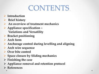

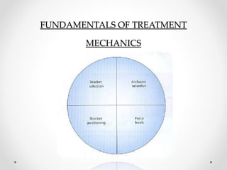

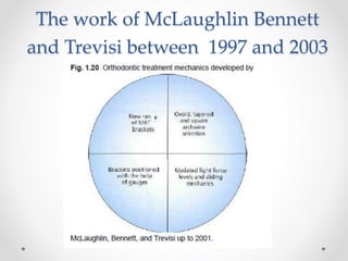
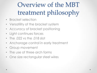
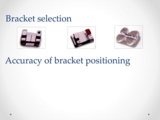


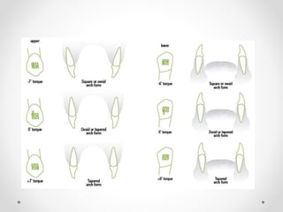
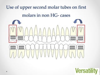
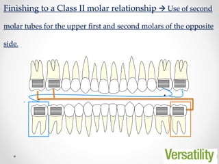
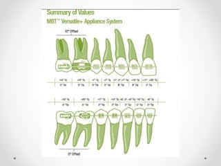

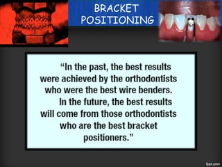

This document provides an overview of orthodontic treatment mechanics using the McLaughlin, Bennett and Trevisi (MBT) bracket system. It discusses the history and development of the MBT system, variations in appliance specifications including bracket selection and torque specifications. It also covers important aspects of treatment including bracket positioning, arch forms, anchorage control, archwire sequences and finishing the case.


