
Recommended
More Related Content
What's hot
What's hot (20)
Similar to Photogyammetry-Notes2.pdf
Similar to Photogyammetry-Notes2.pdf (20)
Recently uploaded
Recently uploaded (20)
Photogyammetry-Notes2.pdf
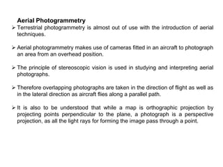
- 1. Aerial Photogrammetry Terrestrial photogrammetry is almost out of use with the introduction of aerial techniques. Aerial photogrammetry makes use of cameras fitted in an aircraft to photograph an area from an overhead position. The principle of stereoscopic vision is used in studying and interpreting aerial photographs. Therefore overlapping photographs are taken in the direction of flight as well as in the lateral direction as aircraft flies along a parallel path. It is also to be understood that while a map is orthographic projection by projecting points perpendicular to the plane, a photograph is a perspective projection, as all the light rays for forming the image pass through a point.
- 2. 1.0.1 Basic Terminology Altitude: Height of the aircraft above the ground. Flying height: Height of the aircraft above a chosen datum. Exposure station: Position of the aircraft at the time of exposure of the film. It is essentially the position of the optical centre of the camera lens when film is exposed. Air base: Distance between two consecutive exposure stations. Tilt and tip: Tilt is an angle produced by the rotation of aerial camera about line of flight (or vertical axis). It is also the angle which the plane of tilted photograph makes with the plane of vertical photograph. Tip is angle produced by the rotation of aerial camera about horizontal axis which is perpendicular to the line of flight. Tip is also called as swing.
- 3. Picture plane: The plane that contains the image at the time of camera exposure. Ground plane: Horizontal surface from which heights can be measured and which can be used as datum surface. Perspective centre: Optical centre of the camera through which all rays of light pass. Principal point: Point of intersection of the optical axis of the camera with
- 4. the photographic plane. O is the optical centre and O´ is the principal point. When the optical axis is extended downwards, the point of intersection with the ground surface is known as principal ground point. Isocentre: Point on the photograph at which the bisector of the angle of tilt meets the photographic plane. In the fig shown on the previous slide ‘i’ is the isocentre, at a distance of f cos along the principal line, where f is the focal length of the camera. Plumb points: The points at which the vertical line through the optical centre meets the photographic plane and the ground surface are the plumb points. The plumb point on the ground surface is also known as ground nadir point and that on the photograph is known as nadir point. Homologous points: Points on the ground and their representations in the photograph in perspective projection. Vertical photograph: Photograph obtained with an aerial camera when the ground is perfectly flat and the optical axis is vertical. This rarely obtained. Tilted photograph: Photograph obtained when the optical axis is inclined unintentionally to the vertical at an angle not greater than 3°.
- 5. Oblique photograph: Photograph taken with the optical axis inclined to the vertical at a large angle. This is done because the view as seen in a vertical photograph is generally unfamiliar to the human eye. The inclination makes the view more familiar. 1.0.2 Equipment for Aerial Surveys: Aircraft fitted cameras is required for aerial surveys. The method is expensive but viable for large projects. Taking photographs is only one part of the job to be done. A lot more work is to be done for stereo plotting in the office with proper equipment.
- 6. Aerial Camera: There is no basic difference in working principle between an ordinary camera and aerial camera. There are several types of cameras in use in aerial photography including digital cameras. The basic principle of working is explained in the fig. below. Aperture: It is opening of the shutter at the time of exposure, which can be adjusted, also called f-stop. The f-stop numbers are given as f/8, f/11 etc. which is focal length divided by effective diameter of the lens opening. Shutter speed: It is the time the shutter remains open to allow the light to fall on the film. This can vary from 1/2000 to 1 or more seconds. Film speed: It is indicated by a number as 100, 200 etc. and means the amount of radiation required for the film response. Larger number indicates large speed, less aperture and small shutter speeds for a given response. Focus: It is the operation for bringing the image clear and is done by varying the distance between the lens and the image plane. When the camera is focused, a clear image of the object will be formed on the plane of the film.
- 7. 1.0.3 Procedure for Aerial Surveying The procedure for aerial surveying includes reconnaissance of the area, establishing ground controls, flight planning, photography and paperwork including computation and plotting. Reconnaissance is undertaken to study the important features of the ground for reference purposes. Ground control points are required in order to obtain a set of points of known positions based on which other points are located or plotted. The number of ground control points depends upon the extent of area covered, scale of the map, flight plan and the process of preparing the map. A minimum three control points must appear in each photograph. In the earlier days of aerial photography, triangulation or precise traverse survey was required to establish control points. These points should be seen prominent and identifiable in the photographs. Both horizontal and vertical control points must be established. Thus the ground coordinates and elevations of these points are known. In modern methods of aerial photography, a number of new technologies are available with total stations and satellite GPS navigators. The ground control points can be established to great accuracy using these new devices. Coordinates in terms of latitude, longitude and elevations can easily be established by these instruments.
- 8. Flight planning includes the decision on the speed of the aircraft, altitude, area covered by each exposure and the overlaps in the direction of flight and in the traverse direction, number of flights, number of exposures and scale of photographs. For the above, the fight plan considers the type of camera and its focal length, scale of the photograph, altitude, speed of aircraft, overlaps of the photographs, area covered by each photograph, time interval between exposures and the number of photographs required. Overlaps are required to ensure complete coverage of the area. Stereoscopic vision is possible only with overlapped parts of the photographs (parts common to two photographs). Overlaps also ensure that the central part of the photograph is less distorted than the outer edges. The photographs are made to overlap longitudinally as well as laterally. Lateral overlap ensures that no area is left without being photographed. Longitudinal overlap is generally 60% while lateral overlap is about 30%. To obtain overlaps, the aircraft flies in a straight line to the extent possible and camera provides exposures as per desired time intervals. The interval between the exposures must be such that the desired longitudinal overlap of the area covered is attained. The next flight is undertaken in parallel line such that the required lateral overlap is obtained.
- 9. Fig below shows how longitudinal and lateral overlaps are obtained. Scale of photographs The representation of any object in the photograph depends upon the distance of the object from the camera. In aerial surveying this distance is represented by flying height. As all the ground features do not have the same elevation, it is obvious the scale representation will be different for features lying at different elevations. A photograph unlike a map (based on orthographic projection) does not have uniform scale. The scale can be varied by changing the flying height. To account for changes in scale due to ground relief (differing elevation), an average elevation and average scale can be worked out.
- 10. Vertical photographs: If the ground is perfectly plane, the photograph obtained will be similar to a map having uniform scale. Referring to the fig. below, the length AB (on plane ground) on the ground is represented by ab in the photograph. So, the scale S of the photograph is ab/AB and from similar triangles abO and ABO; S=ab/ AB = f/(H-h) where f is the focal length of the camera, H is the flying height and h is the elevation of line AB. H and h are measured from the same datum. If A and B are at different levels [Fig (b)] with elevations ha and hb an average elevation for the datum can be used; hav =(ha + hb)/2. Scale for line AB in the photograph can be taken as f/ (H – hav). In case of an area, the elevations of large number of points can be averaged [hav = (h1+h2+h3+……+ hn)/n]
- 11. If the flying height also changes during the coverage of an area, an average flying height can also be worked out and used in the formula for the scale. A vertical photograph, thus, does not have a uniform real scale owing to ground relief. The length of line can be determined using the coordinates on the photograph and on the ground. The ground coordinates are determined with reference to the ground plumb point. The photograph coordinates are determined from the principal point of the photograph. If (X, Y) are the ground coordinates and (x, y) are the photographic coordinates then, (x/ X) = (y/ Y) = f/ (H-h). If PQ is a line, (Xp, Yp) are the ground coordinates of P and (xp, yp) are the photographic coordinates of P and (Xq, Yq and xq, yq) represents the similar terms for Q. X p (H hp )xp f Yp (H hp ) yp f Xq (H hq )xq f Yq (H hq )yq f Length PQ (X X )2 (Y Y )2 p q p q
- 12. Tilted photographs In case of tilted photographs, the scale factor is more difficult to derive. If ground relief is also to be taken into account, the determination of scale becomes very complex. Fig. shows a tilted photograph with angle of tilt ‘t’. Let k = the principal point; n = nadir point; and a = the image point of ground point A nk is the principal line. Draw perpendicular am to the Principal line and mm´ perpendicular to the plumb line. Since the lines am and mm´ are horizontal, the plane amm´ is a horizontal plane. Since Oma is similar to ONA, then ma Om Mapdistance S (scale) NA ON Ground distance But, Om On mn f sect mnsin t where, f is the focal length Ok. If the ground point A is at height h above datum, ON ON0 NN0 H h S f sect mn sin t H h
- 13. Let the photographic coordinates of the image a be x and y as shown in the fig. Now, mn is on the principal axes y which makes clockwise angle with y-axis. x mb ab kd ab x cos and y sin y km kn ed eb kn xsin y cos f tan S f sect ysin t H h From the above equation, it may be observed that the scale is same for all the points along the line ma since the value of y´ is the same. To find the scale at a given point on tilted photograph, the following data is required: (i) focal length f (ii) tilt t (iii) height of flight H (iv) height of point h (v) swing angle θ. Ground Coordinates and Length The coordinates x’ and y’ may be measured on the photograph. The calculation is done as: x am X AM x scale H h x f sec t ysin t
- 14. mm mncost ycost Y NM ycost scale H h ycost f sect ysin t Thus, from photograph coordinates, the ground coordinates can be found. If the photograph coordinates of two points A and B are known, the ground distance between A and B is given by, L Practice Problem The reading on a photograph with 1° tilt on point A and B having elevations of 600 m and 200 m above datum with a camera of focal length 220 mm and flying altitude of 2500 m above the datum are shown below. Point Angle between y-axis and principal line Photographic coordinates x (mm) y (mm) A 20° 42.5 28.2 B 25° -24.0 54.0 Determine the ground length AB. (X X )2 (Y Y )2 a b a b
- 15. Number of photographs to cover a given area Let Pl Longitudinal overlap Pw Side overlap L Ground Length W Width of ground l Length of photograph in flight direction w Width of photograph S Scale (photo to ground) Then, L (1 Pl )Sl W (1 Pw )Sw Ground area covered by each photograph LW (1 Pl )(1 Pw )S 2 lw Number of photographs required to cover the area Area of ground Area covered by a photograph
- 16. Number of photographs required to cover a given area of size L×B Net length covered byeach photograph (1 Pl )Sl Number of photographs requird along a strip N1 L 1 (1 Pl )Sl Similarly net width covered byeach photograph (1 Pw )Sw N2 B (1 Pw 1 )Sw Totalnumber of photographs required Interval between exposure Let v km/h be the uniform velocityof theaircraft Air base beLkm N1N2 Then time required tocover air base L, i.e., the distance between twoexposureis T L hours 3600 L sec onds v v
- 17. Altitude of Aircraft The selection of height above ground depends upon the desired contour intervals of the finished map. Defining C-factor as the number by which the contour interval is multiplied to obtain the maximum height above the ground, Flying height = Contour Interval × C-factor C-factor vary from 500 to 1500 depending upon the conditions surrounding the map compilation operation. Practice Problems 1. The scale of a photograph is 1: 10000 and the size of the photograph is 200 × 200 mm2. Determine the number of photographs required to cover an area of 12 km ×16 km, if the longitudinal lap is 60% and the side lap is 30%. 2. Determine the scale of the photograph and the length of the air base for the data given below: Focal length of camera = 200mm; Flying height = 2000 m above datum; Height of the ground above datum = 500 m; Overlap = 60%; Print size = 250 × 250 mm2. 3. An area of 100 ×100 km2 is to be surveyed by aerial photographs. The following data is available: Focal length of camera= 200 mm; least count of interval meter=0.5 s; size of photograph = 200 mm ×200 mm; average scale of photograph=1:15000; average elevation of terrain = 400m; longitudinal overlap = 60%; side overlap = 30%; velocity of aircraft = 300 km/h. Determine (i) Flying height; (ii) Spacing of flight lines; (iii) Ground distance between exposure; (iv) Exposure interval; (v) Number of photographs required.
- 18. 1.1 Distortions in Aerial Photographs The photographic positions of objects as taken from cameras differ from their orthographic positions, due to the tilt of the camera axis as well as ground relief. These displacements are corrected to some extent before maps are prepared from photographs. Displacement due to tilt Fig. beside shows the displacement Due to tilt, where O is the optical centre, points A and B on the ground are seen as a’ and b’ in the tilted photograph; a and b are the points which would have been obtained in a vertical photograph. The isocentre ‘i’ is obtained by bisecting the angle of tilt passing through O. p is the principal point. pO is a line perpendicular to the picture plane. The angle of tilt is θ. With i as centre Draw two arcs with ia’ and ib’ as radii. These intersect the vertical photograph plane at a” and b”.
- 19. 2 2 2 f Since ib’=ib” by construction, ∆ib’b” is isosceles. In ib’b”, angle at I=, the tilt angle. The remaining two angles at b’ and b” will be equal, i.e., 90- /2. Thus, ib’b” = ib”b’= 90- /2 Also , piO = 90- /2 (As angle at p is 90°) If the lines b’b” and Oi are cut by the line b’a’, then piO and ib’b” are alternate and equal angles, hence the lines b’b” and Oi are parallel. Thus ∆ iOb and ∆b”b’b are similar triangles. Therefore, bb bb ib Oi Oi cos / 2 f sec From ibb, bib ; ibb ib b 90 / 2 Applying sine rule, Ib sin 90 bb sin 2 bb Ibsin 2ibsin( / 2) sin 90 2 [sin(90 / 2) cos / 2 and sin 2sin cos ] From earlier equation for similar triangles bb bb ib 2ibsin( / 2) ib b b Oi f sec / 2 bb ibsin (ib b b) f sec / 2 1/ cos / 2 and 2sin / 2 cos / 2 sin ibsin (ib)2 sin bb 1 f f (ib)2 sin bb f ibsin
- 20. A similar expression can be derived for aa”. The displacement due to tilt can thus be calculated. The distortion due to tilt are radial. The fig shows how a rectangle will be seen in a photograph due to such distortion. Displacement due to ground relief Displacement due to ground relief refers to the displacement of points on the vertical line with respect to each other. Fig shows that the vertical line AB on the ground is seen in the photograph as ab, displaced radially instead of being superimposed as in map. The radial shift may be worked out as below. H is the flying height, f is the focal length, h is the height of B over A. From triangles PbO and OBB; Pb BB where h h h . Similarly from PaO and OAA; f H h b a Pa BB f H Now, Pb H Pa H h or Pb Pa h [the displacement ab Pb Pa] Pa H h the displacement ab h Pa H h It is assumed that the photograph is vertical.
- 21. Problems for practice: 1. Aerial photographs were taken with a camera having a focal length of 180 mm. The average elevation of the ground in the photograph is 160 m. Find (a) the scale of the map if the flying height was 2500 m and (b) the flying height required to have a photo scale of 1 in 6000. 2. On an aerial photograph taken with a camera having a focal length of 150 mm, 1800 m long line PQ had a length of 125 mm. The average elevation of the line PQ was 290 m. Find the scale of another area in the same photograph with an average elevation of 950 m. 3. Find the number of photographs (size 250 mm × 250 mm) required to cover an area of 20 km × 16 km if the longitudinal overlap is 60% and the side overlap is 30%. Scale of the photograph is 1 cm = 150 m. 4. The scale of a photograph of size 250 mm × 250 mm is 1/12000. Determine the number of photographs required to cover an area of 250 km2 if the longitudinal and side overlaps have to be 60% and 30% respectively. 5. In a photograph taken with an aerial camera having a focal length of 200 mm, a line PQ measures 108 mm. If the same line has a length of 40 mm on a map drawn to a scale of 1:40000, find the flying height of the aircraft if the average elevation is 400 m.
- 22. 6.In a vertical photograph, a line 2100 m long measures 110 mm. If the average elevation of the line is 480 m, find the scale of an area in the same photograph with an average elevation of 1200 m. The focal length of the camera used is 210 mm. 7.Points P and Q have elevations of 600 m and 300 m respectively. The photographic coordinates of points P and Q were measured as P(35, 25) and Q(20, 50) in millimeters. The photograph was taken with a camera having a focal length of 210 mm and from an altitude of 2500 m. Find the length of line PQ. 8.The height of a chimney is 110 m. In a vertical photograph taken from an altitude of 2800 m, the chimney appears at a distance of 70 mm from the principal point. Determine the displacement of the top of the chimney from the bottom if the elevation of the base is 1200 m. 9.The image of the base and top of a 200 m tower is seen in a photograph of scale 1:15000. If the base point is 65 mm from the principal point, find coordinate of the top from the principal point. The focal length of the camera was 200 mm and assume that the base of the tower is datum plane. 10. An aerial photo 250 mm × 250 mm was taken with a camera having a focal length of 200 mm. At the time of exposure, the tilt was assumed to be 1.5°. Find the displacement of a point lying at 70 mm on a line passing through the principal point.
- 23. 1.2 Mosaics An assemblage of aerial photographs whose edges have usually been cut and matched to form a continuous photographic representation of the particular area is called a mosaic. Generally the mosaic contains the centre portion of the photograph which has generally an average scale. If this assemblage is made without any control, then it is called uncontrolled mosaic. If, before being laid, the prints have been properly rectified, i.e., enlarged or reduced and fitted on adequate ground control, i.e., to fit pre-determined locations of certain important features, the mosaic is said to be a controlled mosaic. The controlled mosaic, though more accurate, retains the changes in scale and displacements due to differences in relief within the individual prints. A contoured mosaic shows the relief by means of contours, and may be either controlled or uncontrolled. A semi controlled mosaic may be prepared from unrectified photograph assembled to have ground control; alternatively rectified photographs may be used with no ground control. Semi-controlled mosaics are a compromise between economy and accuracy.
- 24. 1.5.1 Photographs and maps: An aerial photograph is a two dimensional view of an area at an instant of time. Maps, on the other hand, are made with data collected at some point of time. It takes time to prepare the map and some of the measured data may be outdated by the time the map gets prepared. Aerial photographs do not have uniform scale over the whole area. The image is also distorted due to tilt and ground relief. Maps are drawn to a uniform scale. A photograph is a perspective projection whereas a map is an orthogonal projection. A photograph gives full details of landscape, including the insignificant details. Maps, on the other hand, can be made to exact details the customer wants, i.e., important features required for the project. An air photograph shows details as seen by the camera. A map on the other hand, shows details using conventional symbols. 1.3 Stereoscopic Vision Stereoscopic vision essentially lends height or depth to the object in the photograph as it would have been seen by the human eye. If photographs are available in stereo-pairs, it is possible to get a three dimensional view of the object. Stereoscopic or binocular vision The human brain receives two images of the same object through the two eyes as seen from slightly different angles and fuses them into a 3-d view.
- 25. The base length for vision by human eyes is about 65 mm. As shown in the fig. beside PQ is the object. Each eye sees the object but from slightly different angle: 1 and 2 known as parallax angles. The two images received by the retina are fused into a single image giving depth to the vision. When the distance between eyes and object is very large, the parallax angles become smaller and at about 600 m the relative depth is no longer perceived by the eye. Stereoscopic pairs To enable stereoscopic vision, it is essential to have photographs in pairs covering common areas. In aerial photography, photographs are taken from two camera positions with sufficient overlap in the photographs. Only the areas seen in both the photographs are amenable to stereoscopic vision. The common part of the photographs give us two views of the same object from slightly different angles, as seen by human eyes. When the photographs are suitably placed and the left eye views one and the right eye views the other, the common area comes in relief or in three dimensions due to stereoscopic fusion. Stereoscopic vision enables one to view the depth or height of points on the photograph.
- 26. Stereoscope There are many types of stereoscopes: mirror stereoscope, lens stereoscope, scanning mirror and zoom stereoscope. Mirror and lens stereoscopes are handy and commonly used. Mirror Stereoscope The schematic diagram of mirror stereoscope is shown in the fig. beside. It consists of two viewing eyepieces. A stereoscopic pair of photographs is placed at a distance from the stereoscope. The photographs are adjusted so that one photograph is seen through one eyepiece. As the viewer looks through the stereoscope, he sees the image of the same object (the overlapping part) on the two photographs, the viewer gets a stereoscopic view by fusion. The terrain is seen in three dimensional view. Lens stereoscope A lens stereoscope has two eyepieces through which the observer sees the photographs, providing the experience of stereoscopic or spatial view. The lenses help to magnify the image as seen by each eye. The distances between the eyepieces is adjustable and can be set by the observer as required.
- 27. This distance is approximately equal to human eyes. The lenses tend to magnify the object and its height. Lens stereoscope are more compact than mirror stereoscopes. 1.4 Photo-interpretation Photo-interpretation refers to the accurate identification of features seen in the photographs. It is more difficult to identify objects in vertical photographs than in tilted photographs owing to familiarity of view in oblique photographs. Colour photographs are easier to interpret than black and white photographs due to tonal variations. A stereoscopic pair is easier to interpret due to depth available in photographs when seen through a stereoscope. Interpretation of aerial photographs is required extensively in developmental project design and execution. Considerable amount of practice and experience is required to correctly interpret the photographs. General Features of Photographic Images Some of the basic features of photographs that help in identification are discussed here. (i)Size: The size of an object in the photograph is sometimes helpful in interpretation. Knowing the photograph scale, it is possible to have an idea about the size. The size distinguishes the objects of similar shape in photograph such as a river, road, canal or drain.
- 28. (ii) Shape: The shape of an object is helpful in identifying an object. Regular shaped objects are generally man-made. Shape relates to the general outline of the object. A railway line and a roadway can be distinguished from their form. Objects of same size can be distinguished from their shape. (iii)Texture: It is simply variation in tone of the photograph. It is produced by a combination of factors such as size, shape, tone pattern and shadow. Vegetation and other ground features can be distinguished by the tonal changes. (iv) Pattern: It is spatial arrangement of objects in a particular set. A habitat can easily be distinguished by the arrangement of roads, houses etc. because of the pattern. (v) Shadow: The shadow of an object formed during photography is sometimes helpful in identification, as it shows the outline of the object. (vi) Tone: It produced by the amount of light reflected back by the object to the camera. If the particular tone associated with specific objects are known, it is easy to identify them. (vii)Location: The location of an object in the photograph helps in identifying the object itself. Knowing the objects or areas surrounding the object, one can identify the main object.
- 29. 1.5 Parallax Parallax of a point is the displacement of the image of the point on two successive exposures. a1 is the position of ground point A in photograph at O1. a2 is the position of ground point A in photograph at O2. Taking the line of flight as x-coordinate, let xa be the coordinate of a1 in photograph at O1 and x'a the coordinate of a2 in photograph at O2. Then Parallax of A p = xa - x'a (Algebraic sign of xa and x'a should be taken into consideration, e.g., if xa=32.5 mm and x'a=-28.4 mm, p = 32.5 – (-28.4) = 60.9 mm)
- 30. 1.6 Errors in Aerial Survey Failure to maintain altitude of aircraft. Inaccuracies in locating and transferring the principal points. Failure to see the floating mark correctly on the point. Inaccurate orientation of photographs while preparing maps. Neglecting the tilt of camera. Failure to provide proper control points. Reading the scales incorrectly.