TataKelola dan KamSiber Kecerdasan Buatan v022.pdf
Rf power amplifier
1. RF power amplifier
A RF amplifier is a device for electrically amplifying the power of an electrical signal,
typically, but not exclusively, radio frequency signals.
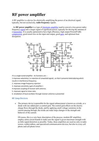
An RF power amplifier is a type of electronic amplifier used to convert a low-power radio-
frequency signal into a larger signal of significant power, typically for driving the antenna of
a transmitter. It is usually optimized to have high efficiency, high output Power(P1dB)
compression, good return loss on the input and output, good gain, and optimum heat
dissipation.
rf is a single tuned amplifier . Its functions are :-
1.improves selectivity ( i.e rejection of unwanted signal) , so that it prevents heterodyning which
results in interference frequency.
2. improves image frequency rejection
3. improves sensitivity ( gain of amplifier )
4.improves coupling of receiver with antenna .
5. improves signal to noise ratio.
6. reradiation of local oscillator through receiver antenna is prevented
RF Amp Devices
The primary device responsible for the signal enhancement is known as a triode, or a
diode with one added part--a control grid. The control grid affects on the electric
charge flows through the diode, and by applying small voltage variations in the
current passing through, the triode can make large changes in the strength and
behavior of the current.
Of course, this is a very basic description of the process: modern RF amplifiers
employ entire circuit boards to make sure the signal is given maximum strength with
as little signal distortion as possible. Today, these amplifiers are used no only in radio
towers, walkie-talkies, and specialized communication devices, but also in every cell
phone and cell phone tower.
2. Service Data Chart For Troubleshooting the RF Amplifier Stage
Symptom Abnormal Reading Possible Cause
RF Stage
Inoperative
Plate voltage = 0. Other
voltages normal
Open primary (L4) of interstage transformer T-2.
Open plate resistor R-4.
Plate de-coupling capacitor C-4 shorted
Screen voltage = 0. Other
voltages normal
Screen by-pass capacitor C-14 shorted.
Screen resistor R-14 open
All voltages normal Check for short in gang tuning capacitor C-2.
Defective tube
Cathode high Open cathode resistor R-1
Cathode voltage = 0 Shorted cathode by-pass capacitor C-1
Dead tube
Weak signal All voltages normal Weak tube.
Check for open winding (L1-L2) on antenna
transformer T-1.
Open plate by-pass capacitor C-4.
Open AVC by-pass capacitor C-30.
RF stage out of alignment
Oscillation All voltages normal Open screen by-pass capacitor C-14.
Tube shield not making good ground
connection.
Noisy operation All voltages normal Open or corroded antenna transformer T-1.
Open AVC by-pass capacitor C-30.
Corrosion in the interstage transformer T-2.
Defective tube.
Defective gang tuning capacitor C-2 (check for
grounding wipers making poor contact).
Dirty trimmer capacitor C-2A
Poor tone
quality
All voltages normal Shorted AVC by-pass capacitor C-30.
3. Ground waves
In physics, a surface wave is a mechanical wave that propagates along the interface between
differing media, usually two fluids with different densities. A surface wave can also be an
electromagnetic wave guided by a refractive indexgradient. In radiotransmission, a ground wave is a
surface wave that propagates close to the surface of the Earth
Ground waves refer to the propagation of radio waves parallel to and adjacent to the surface of the
Earth, following the curvature of the Earth. These surface waves are also known loosely as the
Norton surface wave, the Zenneck surface wave, Sommerfeld waves, and gliding waves.