Production of Electrical Energy by Vertical Axis Maglev Windmill
•
3 likes•102 views

This paper deals with wind power generation by elimination of gear system. Using magnetic levitation frictional losses will be avoided and power generated will be improved. Comparing with conventional type vertical axis wind turbine is more efficient that will capture the wind in all directions. Due to maglev, it will be able to rotate in minimum speed of 1m/s and produce alternating voltage. By using permanent magnet (Neodymium) repulsion effect replaces the bearings to reduce the frictional losses and produce power more than conventional type with cost effective.

Recommended
Recommended
More Related Content
What's hot
What's hot (19)
Similar to Production of Electrical Energy by Vertical Axis Maglev Windmill
Similar to Production of Electrical Energy by Vertical Axis Maglev Windmill (20)
More from Premier Publishers
More from Premier Publishers (20)
Recently uploaded
Recently uploaded (20)
Production of Electrical Energy by Vertical Axis Maglev Windmill
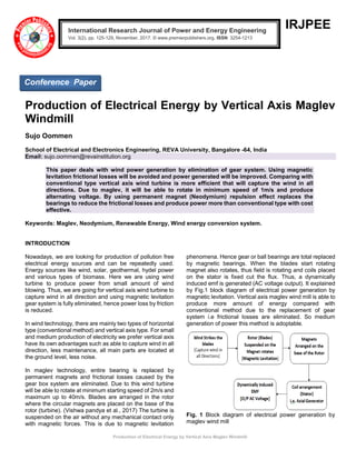
- 1. Production of Electrical Energy by Vertical Axis Maglev Windmill IRJPEE Production of Electrical Energy by Vertical Axis Maglev Windmill Sujo Oommen School of Electrical and Electronics Engineering, REVA University, Bangalore -64, India Email: sujo.oommen@revainstitution.org This paper deals with wind power generation by elimination of gear system. Using magnetic levitation frictional losses will be avoided and power generated will be improved. Comparing with conventional type vertical axis wind turbine is more efficient that will capture the wind in all directions. Due to maglev, it will be able to rotate in minimum speed of 1m/s and produce alternating voltage. By using permanent magnet (Neodymium) repulsion effect replaces the bearings to reduce the frictional losses and produce power more than conventional type with cost effective. Keywords: Maglev, Neodymium, Renewable Energy, Wind energy conversion system. INTRODUCTION Nowadays, we are looking for production of pollution free electrical energy sources and can be repeatedly used. Energy sources like wind, solar, geothermal, hydel power and various types of biomass. Here we are using wind turbine to produce power from small amount of wind blowing. Thus, we are going for vertical axis wind turbine to capture wind in all direction and using magnetic levitation gear system is fully eliminated, hence power loss by friction is reduced. In wind technology, there are mainly two types of horizontal type (conventional method) and vertical axis type. For small and medium production of electricity we prefer vertical axis have its own advantages such as able to capture wind in all direction, less maintenance, all main parts are located at the ground level, less noise. In maglev technology, entire bearing is replaced by permanent magnets and frictional losses caused by the gear box system are eliminated. Due to this wind turbine will be able to rotate at minimum starting speed of 2m/s and maximum up to 40m/s. Blades are arranged in the rotor where the circular magnets are placed on the base of the rotor (turbine). (Vishwa pandya et al., 2017) The turbine is suspended on the air without any mechanical contact only with magnetic forces. This is due to magnetic levitation phenomena. Hence gear or ball bearings are total replaced by magnetic bearings. When the blades start rotating magnet also rotates, thus field is rotating and coils placed on the stator is fixed cut the flux. Thus, a dynamically induced emf is generated (AC voltage output). It explained by Fig.1 block diagram of electrical power generation by magnetic levitation. Vertical axis maglev wind mill is able to produce more amount of energy compared with conventional method due to the replacement of gear system i.e frictional losses are eliminated. So medium generation of power this method is adoptable. Fig. 1 Block diagram of electrical power generation by maglev wind mill International Research Journal of Power and Energy Engineering Vol. 3(2), pp. 125-129, November, 2017. © www.premierpublishers.org, ISSN: 3254-1213x Conference Paper
- 2. Production of Electrical Energy by Vertical Axis Maglev Windmill Oommen S. 126 A. Power Calculation For the sufficient generation of power there are some factors have to consider such as the wind availability in an area and the velocity of the wind. (Minu John et al., 2014) The wind power increases as the cube of velocity of the wind (speed) with respect to area. (Harshal Vaidyal et al., 2016) The motion of the wind is considered as the kinetic energy (Piyush Gulve, and Dr. S.B.Barve, 2014). Kinetic Energy K.E = ½ ρAV3 To convert into Power in kilowatt, a proportionality constant is added, K= 2.14 x 10⁻³ Therefore, Power on kilowatt (KW) = 2.14 ρAV3 x10-3 Where, ρ is Air density = 1.2Kg/3/2.33 x10-3 slugs/f3 A is Area swept out by the blades V is wind speed velocity in m/s We can use only a portion of overall wind power, that cannot exceed 59% of the overall wind. Magnetic Levitation Magnetic Levitation means repulsive force characteristics between the permanent magnets and able to suspends the object without any contact only with magnetic forces (Minu John, 2014). We are using neodymium magnets (Nd- Fe- B) have placed like polarities on the top of each other. Compared with other permanent magnets repulsive force is that much strong enough to carry the weight of the turbine. As the grade of the magnet increases the repulsive forces also increases. Due to levitation gaer system is completely replaced by magnetic bearings hence frictional losses are eliminated and power generation can be increased by 20%. Hence the starting speed is reduced, output power will be obtained for lower speed also. As the mechanical bearing is eliminated lubrication also is not required and is reliable. Fig 2: Magnetic Levitation B. Selection of magnets & Arrangement From Fig 3. (Minu John et al., 2014) B-H curve of different magnets, neodymium (Nd-Fe-B) have maximum magnetic flux density so able to produce maximum flux for the generation of voltage. We selected two different shapes of Neodymium magnet N35 grade in which 14 circular magnets and 2 centre magnets. Fig.3 B-H curve of Various Permanent Magnets The dimension of the magnets is outside diameter of 40mm, inside diameter of 20mm and width of 10mm. these permanent magnets are plated with nickel to protect and strengthen the magnet. The magnets used in this design N- 35 grade Nd-Fe-B having a flux density of 2100 Gauss(green colour) from the Fig.4. We are used 2 ring shaped magnets and 14 circular magnets. The ring shaped magnets placed on the shaft with like poles repel each other and circular shaped arranged in N-S N-S like that shown in Fig.5. Fig.4 Flux lines around Permanent Magnet
- 3. Production of Electrical Energy by Vertical Axis Maglev Windmill Int. Res. J. Power Energy Engin. 127 Fig.5 Arrangement of Circular Neodymium Magnets on the base of the Rotor C. Coil Arrangement Coils used for power generation is 46-gauge wires of 5000 turns each and have four sets of coils. They are arranged in the periphery of the stator which is in a line to disc magnets and raised to certain height for maximum utilization of magnetic flux. Coils are connected in series over parallel to obtain more amounts of output voltage and current. As the magnet fixed to the turbine rotates, a rotating field is developed and the coils are fixed at bottom base cut the magnetic flux a dynamically induced emf is generated in the coil (axial generator). The coils are arranged near to it for getting flux changes and produce more output voltages. Fig 6 Coil Arrangement D. Blades Design Details The blades design details are given in the TABLE. I. (Vishal D Dhareppgoal and Maheshwari M Konagutti, 2013) The number of blades used is 8 and angle should be in the range of 300 to 450 with the disc. As to capture maximum amount of wind, angle of the blades should be 450 will makes to rotate the turbine faster. If the no. of blades increases, it will create turbulence to the system and if it is less, it may not be able to capture maximum amount of wind. Side view and top view of the blades arrangement is shown below Fig.7 & Fig.8 respectively. Due to this deign even in very less wind it will be able to rotate and produce energy. Table I Type Specification Cylindrical Outer Diameter of Blade 400 mm Cylindrical inner Diameter of Blade 80 mm Wings 600 * 120 mm Angle Cutting 450 Blade Cuttings 97/100/298.5/301.5/500/503/600 Fig.7 Side View of Blades arrangement Fig.8 Top View of Blades arrangement
- 4. Production of Electrical Energy by Vertical Axis Maglev Windmill Oommen S. 128 Hardware Implentation The overall structure of the maglev wind mill designed is shown in the Fig.9 and output obtained using w.r.t speed is given in the TABLE II. The output produced (4-6V) from the wind mill is alternating current (AC) is converted into DC using rectifier circuit. DC obtained from the rectifier module is doubled by a voltage doubler circuit. This output from doubler is fed to the inverter module to get AC and connect to the load (as here CFL). Fig.9 Experimental setup of maglev wind mill E. Rectifier Module & Voltage Doubler Circuit A full wave diode bridge module is used for to obtain pulsing DC (4-6V) shown in Fig.10 helps to increase the average output voltage. Capacitor of 500 µF is used for remove harmonics. This filtered voltage is doubles input voltage of 5V to 10V using 555 timer IC, 0.01mF & 22mF capacitor for charging & discharging form a voltage doubler circuit and maintains the constant voltage shown in Fig.11 Fig. 10 Rectifier Module Fig.11 Voltage Doubler Circuit F. Inverter Module It aims to convert DC to AC power by using PWM to get complete the desired output and boost up the voltage by a step up transformer to 110V. Fig.12 Inverter Module Table. II Sl.No. Speed Vs Output Power Speed in RPM Output Voltages(V) Current(mA) Power(mW) 1. 19 1.8 0.1 0.18 2. 38 2.5 0.2 0.50 3. 57 3.6 0.5 1.80 4. 105 4.8 0.9 4.32 5. 124 6.5 1.3 8.45 6. 171 10.7 1.8 19.26
- 5. Production of Electrical Energy by Vertical Axis Maglev Windmill Int. Res. J. Power Energy Engin. 129 CONCLUSION This type of turbine can be used for moderate production of electrical energy. The wind turbine rotor and stator levitated properly using Neodymium magnet N35 grade which help the smooth rotation without any friction. We can able to produce moderate amount of power even with less wind speed of 2m/s. as the grade of the magnet increases magnetic levitation also will be more stable, life of the magnet increases. For the increase of current, gauge of the wire as well as the number of turns also should increases. As we are going for vertical axis type it is best to implement for domestic purpose less expensive compared with solar. REFERENCES Dinesh N Nagarkar and Khan Z. J. (2013). Wind Power Plant Using Magnetic Levitation Wind Turbine. International-Journal of Engineering and Innovative Technology (IJEIT) Volume 3, Issue 1. Minu John, Rohit John, Syamily P.S, and Vyshak P.A (2014). Maglev Windmill. International Journal of Research in Engineering and Technology, Volume: 03, Issue: 05. Harshal Vaidya, Pooja Chandodkar, Bobby Khobragade, R.K. Kharat (2016). Power Generation using Maglev Windmill. International Journal of Research in Engineering and Technology, Volume: 05 Issue: 06, eISSN: 2319-1163 | pISSN: 2321-7308 Piyush Gulve, and Dr. S.B.Barve (2014). Design And Construction Of Vertical Axis Wind Turbine. International Journal of Mechanical Engineering and Technology (IJMET), Volume 5, Issue 10, pp. 148-155. Vishal D Dhareppgoal and Maheshwari M Konagutti (2013). REGENEDYNE Maglev Wind Power Generation. SARCIRAJ International Conference, Pune, India. Vishwa pandya, Devanshi Vyas, Ashwini Yadav (2017). Electricity production by Magnet(Maglev Mill). National Conference on Emerging Trends, Challenges & Opportunities in Power Sector(IJSRD), ISSN: 2321- 0613. Accepted 23 October, 2017 Citation: Oommen S (2017). Production of Electrical Energy by Vertical Axis Maglev Windmill. International Research Journal of Power and Energy Engineering, 3(2): 125-129. Copyright: © 2017. Oommen S. This is an open-access article distributed under the terms of the Creative Commons Attribution License, which permits unrestricted use, distribution, and reproduction in any medium, provided the original author and source are cited.