There are many aims for this paper such as to apply renewable energy for everyone in Myanmar, to supply electricity to rural areas not only offgrid but also ongrid and to construct wind turbines widely in costal region starting from this research. The proposed wind power system is 450W in Pyay. This proposed system may be costed around US $1700. As Bago Mountainuous Region is also situated in Pyay District, wind power can produce electricity. Moreover, 49 villages is no electricity among 567 villages. In this paper, five main components is expressed such as wind turbine, permagnet generator, rectifier, battery and inverter. Dr. Zarchi San | Daw Yin Aye Mon | Daw Lin Lin Phyu ""Proposed Wind Power System in Pyay District in Myanmar"" Published in International Journal of Trend in Scientific Research and Development (ijtsrd), ISSN: 2456-6470, Volume-3 | Issue-3 , April 2019, URL: https://www.ijtsrd.com/papers/ijtsrd22782.pdf
Paper URL: https://www.ijtsrd.com/engineering/electrical-engineering/22782/proposed-wind-power-system-in-pyay-district-in-myanmar/dr-zarchi-san
2. International Journal of Trend in Scientific Research and Development (IJTSRD) @ www.ijtsrd.com eISSN: 2456-6470
@ IJTSRD | Unique Paper ID - IJTSRD22782 | Volume – 3 | Issue – 3 | Mar-Apr 2019 Page: 348
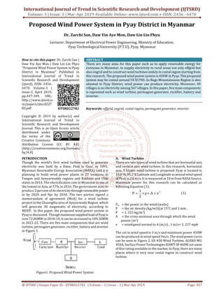
Figure2. Wind Power Curve
The required tower height can get from Equation (2).
α
oo
)
H
H
(
v
v
= (2)
v = the windspeed at height H ,
v0 = the windspeed at height H0 (reference height of
10 m),
α = the friction coefficient
This wind turbine can produce the maximum power at the
height of tower 650 m.
B. Generator Consideration of Wind Power System
In comparison to induction generator, the use of
synchronous generator is advantageous since they are self-
excited machines and the pole pitch of the machine can be
smaller. It is generallyfavoredin newer smallerscaleturbine
designs, since it allowsforhigher efficiency andsmaller wind
turbine blade diameter. The primary advantage of
permanent magnet synchronous generator (PMSG) is that
they do not require any external excitation current. To
calculate the speed of generator and gear ratio, Equation 3
and 4 are expressed.
Dπ
v60TSR
rpm
×
××
= (3)
rpm = the rotor speed, revolutions per minute
D = the rotor diameter (m)
v = the wind speed (m/s) upwind of the turbine
rpmRotor
rpmGenerator
ratioGear = (4)
The speed of generator is 600 rpm because of tip speed ratio
is 3.4 and the result of gear ratio is 1.25.
C. LM 317 Voltage Regulator
The output of generator is the input of voltage regulator and
the output of voltage regulator goes to battery. There is an
input, an output, and an adjustment terminal in LM317. The
external fixed resistor R1 and the external variable resistor
R2 provide the output voltage adjustment. VOUT can be varied
from 1.2 V to 37 V depending on the resistor values. The
LM317 can provide over 1.5 A of output current to a load.
The LM 317 voltage regulator is shown in Figure 3. The
output voltage can be get by solving Equation (5).
Figure3. The LM317 three-terminal adjustable positive
voltage regulator
2RADJI)
1R
2R
1.25(1outV ++= (5)
The output voltage of LM 317 is 12 V by substituting R1 =
1kΩ and R2 = 10 kΩ .
D. Battery
The overall cost of the lead-acid battery is low compared to
Nickel-cadmium (NiCd), Nickel-metal hydride (NiMH) and
Lithium-ion (Li-ion) batteries. Because of its least cost per
Wh delivered over the life, the lead-acid batteryhasbeenthe
workhorse of the industry. Battery capacity, voltage and
current ofcharging and discharging state are calculated as
follows.
Charging voltage=charging voltage per cell x number of cell
=2.25 x 6 =13.5V (fully charged)
Discharging Voltage
= discharging voltage per cell x number of cell
=1.75 x 6 =10.5V (fully discharged)
Battery capacity = Whr/voltage = 400/12 = 30 Ah
Choose two parallel 12V 14Ah lead-acid battery.
Charge or discharge current, I = Ah/hr = 28Ah/7h = 4A
E. Inverter
An inverter is an electronic device or circuitry that changes
direct current (DC) to alternating current (AC). The square
wave inverter is one of the simplest waveforms among
others such as pure sine wave inverter, modified sine wave
inverter and is best suited to low-sensitivity applications
such as lighting and heating. Square wave" is the term used
when the electricity has a constant force, such as it has with
DC but switches direction more or less instantly at the same
kind of frequency as the normal grid supply (at 50 times per
second). Component of the inverter circuit
1. Transistor (2N 3636 & 3055) 4nos
2. Capacitor 2nos
3. Resistor 2nos
4. Center tapped Transformer (12-12/230V) 1nos
The following Figure 4 is used to change battery 12 V DC to
230 V AC load. In this Figure, Q1 and Q2 are used for
oscillation. Q3 and Q4 are used to getthepositivepolarityand
negative polarity. R1 and R2 are used for basing theQ1 and Q2
and R3 and R4 are used for basing the Q3 and Q4.
Figure4. 12 V DC to 230 V AC Inverter Circuit
3. International Journal of Trend in Scientific Research and Development (IJTSRD) @ www.ijtsrd.com eISSN: 2456-6470
@ IJTSRD | Unique Paper ID - IJTSRD22782 | Volume – 3 | Issue – 3 | Mar-Apr 2019 Page: 349
Result
The proposed wind power system in Pyay is 450 W with cut
in 3m/s and rated wind speed 9 m/s. For this wind turbine,
the number of blade is 5 and tower height is required to be
650m. Due to wind, generator can produce electricity with
maximum power 450W. The primary advantage of
permanent magnet synchronous generator (PMSG) is that
they do not require any external excitation current. LM 317
voltage regulator is applied togetoutput voltagetobestable.
Two numbers of 12 V, 14 Ah battery is needed to back up
supply while no wind blows. AC load can connect to 12 V –
230 V, 450W inverter.
Table1. Main Components and Specifications
Main Components Specification
Wind Speed 3 m/s ~ 9 m/s
No: of Blade 5
Height of Wind Turbine 650 m
Generator 450W , 12V
Voltage Regulator Circuit LM 317
Battery 12 V , 14 Ah ( 2 No: )
Inverter 450W , 12V-230 V
In Pyay, there are many mountains so wind turbine can be
constructed. From NASA source, the annual wind speed is
about 2.6 m/s. In this paper, 450W wind turbine is
disscussed and the rated wind speed is 9 m/s. As wind is not
steady, the output is notconstant. LM 317 voltage regulator
can regulate the output voltage. The following Figure 5 is
simulation result of LM 317. The output voltageisabout10.2
V when the input is 12 V. The resistors R1 and R2 are
calculated.
Figure5. Simulation Result of LM 317
To supply AC load, inverter is required and Figure 6 is
simulation result of square wave output of inverter. The
straight line with blue color is DC 12 V and the square wave
with red color is for output 230 V. Square wav is used when
the electricity has a constant force, such as it haswithDC but
switches direction more or less instantly at the same kind of
frequency as the normal grid supply (at 50 times per
second).
Figure6. Simulation Result of Square Wave Output of
Inverter
Recommendations
Our research group needsto have connectiontoGovernment
Society for practical works. The simulation results and
experience results should compare and note to give
conclusion. Another software as MATLABcanbechecked for
this proposed system. Moreover, battery charging circuit
that can protect over charging and under charging can be
further added in the original circuit.Hybrid with solar can be
connected for this system. If so, more power beyond 450W
can be drawn.
Conclusion
Though the electrification rate in Myanmar is one of the
lowest in Asia, at 57% in 2016, Myanmar Government aims
to produce 2 percent of its electricity through renewable
power in by 2020 and 9 percent by 2030. In this paper, 450
W wind power system in Pyay is discussed. The simulation
results of voltage regulator and inverter are expressed.
Though maximum supplied load of Pyay is now 72.06MW in
2018-19, it can be increased to 109.56MW in 2021-22.
Renewable energy using isoneof simplesolutions. Rules and
regulations should be limited in time before all projects that
do not begin. Starting only one wind turbineshould continue
big wind farm for tourists’ attraction in ancient town Pyay.
References
[1] Control of Wind Energy Output by using Impedance
Source Inverter, Ph.D thesis, Zarchi San, 2017
[2] Floyd, Thomas L. Electronic devices : conventional
current version / Thomas L. Floyd.— 9th ed.
[3] Google search
[4] J. L. Rodriguez-Amenedo, S. Arnalte, and J. C. Burgos,
“Automatic generation control of a wind farm with
variable speed wind turbines,”IEEE Transaction on
Energy Conversion, vol. 17, no. 2, pp. 279–284, Jun.
2002.
[5] Renewable and Efficient Electric Power Systems,
Gilbert M. Masters, Stanford University
[6] X. Wei, X. Qiu, J. Xu, and X. Li, “Reactive Power
Optimization in Smart Grid With Wind Power
Generator,” in 2010 Asia-Pacific Power and Energy
Engineering Conference, 2010, no. 2, pp. 1–4.
[7] Z. Chen, J. M. Guerrero, F. Blaabjerg, "A review of the
state of the art of power electronics for wind turbines,"
IEEE Trans. Power Electronics, vol.24,no.8,pp.1859-
1875, Aug 2009