Download to read offline

![6
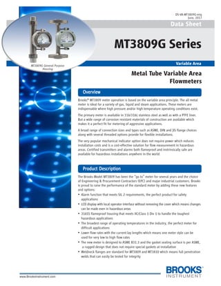
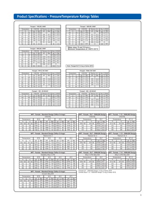
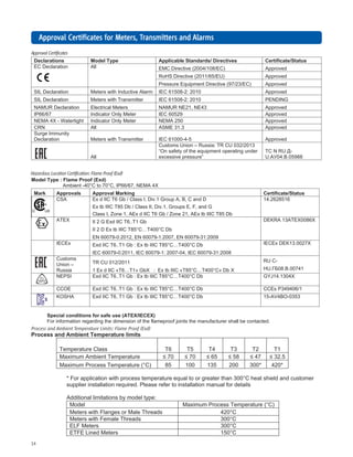
PrPrPrPrProduct Dimensions - Generoduct Dimensions - Generoduct Dimensions - Generoduct Dimensions - Generoduct Dimensions - General Purpose Housingal Purpose Housingal Purpose Housingal Purpose Housingal Purpose Housing
141 5.57
137 5.40
B
98 3.85
D
C
A 1.5[1/16]
141 5.57
B
137 5.40
A 1.5[1/16]
C
98 3.85
D
Model 3809 & 3810 General Purpose Indicator Housing with
Flanged Connections mm [inches]
Model 3809 & 3810 General Purpose Indicator Housing with
Threaded Female St'd Connections mm [inches]
* Dimensions apply to threaded female standard connections only.
** Weights shown for aluminum indicator. Add 1.8 kg [4 lbs.] for steel indicator housing.
Meter
Size
Connection A B C D Weight (Approx.)**
0-5
7 & 8
10
12
13
1/2" Threaded Female St'd
1/2" Threaded Female St'd
1" Threaded Female St'd
1-1/2" Threaded Female St'd
2" Threaded Female St'd
225 [8.85]*
225 [8.85]*
300 [11.81]*
300 [11.81]*
300 [11.81]*
99 [3.90]
99 [3.90]
107 [4.21]
116 [4.57]
122 [4.78]
63 [2.48]
63 [2.48]
71 [2.80]
80 [3.15]
86 [3.39]
76 [2.98]
76 [2.98]
76 [2.98]
76 [2.98]
76 [2.98]
2.7 kg [6 lbs. ]
2.7 kg [6 lbs. ]
4.5 kg [10 lbs. ]
6.8 kg [15 lbs. ]
7.7 kg [17 lbs. ]
0-5
7 & 8
10
12
13
15
16
1/2" Flange
1/2" Flange
1" Flange
1-1/2" Flange
2" Flange
3" Flange
4" Flange
250 [9.84]
250 [9.84]
250 [9.84]
250 [9.84]
250 [9.84]
250 [9.84]
350 [13.78]
99 [3.90]
99 [3.90]
106 [4.18]
115 [4.54]
121 [4.63]
139 [5.46]
152 [5.98]
63 [2.48]
63 [2.48]
70 [2.76]
79 [3.12]
85 [3.36]
103 [4.05]
118 [4.65]
76 [2.98]
76 [2.98]
76 [2.98]
76 [2.98]
76 [2.98]
76 [2.98]
126 [4.95]
4.1 kg [9 lbs. ]
4.1 kg [9 lbs. ]
7.7 kg [17 lbs. ]
12.2 kg [27 lbs. ]
14.1 kg [31 lbs. ]
20.0 kg [44 lbs. ]
37.6 kg [83 lbs. ]](https://image.slidesharecdn.com/variable-area-flow-meter-data-sheet-mt3809g-mt3809elf-mt3809tfe-mt3810-170626184524/85/Metal-Tube-Variable-Area-Flow-Meter-6-320.jpg)
![7
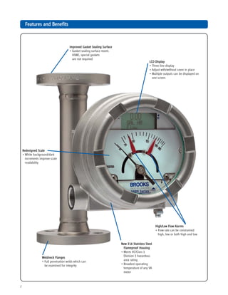
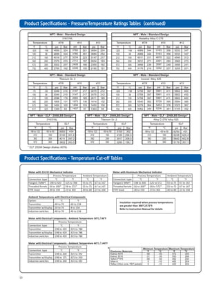
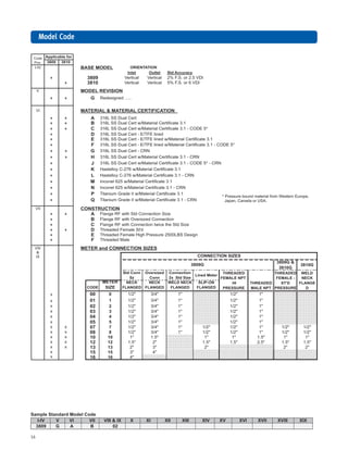
PrPrPrPrProduct Dimensions - Inoduct Dimensions - Inoduct Dimensions - Inoduct Dimensions - Inoduct Dimensions - Intrinsically Safe Housingtrinsically Safe Housingtrinsically Safe Housingtrinsically Safe Housingtrinsically Safe Housing
B
160 6.29
A 1.5[1/16] 160 6.29
D
C
160 6.28
B
A 1.5[1/16]
160 6.29
D
C
Model 3809 Intrinsically Safe Indicator Housing with
Threaded Female St'd Connections mm [inches]
Model 3809 Intrinsically Safe Indicator Housing with
Flanged Connections mm [inches]
* Dimensions apply to threaded female standard connections only.
Meter
Size
Connection A B C D Weight (Approx.)
0-5
7 & 8
10
12
13
1/2" Threaded Female St'd
1/2" Threaded Female St'd
1" Threaded Female St'd
1-1/2" Threaded Female St'd
2" Threaded Female St'd
225 [8.85]*
225 [8.85]*
300 [11.81]*
300 [11.81]*
300 [11.81]*
104 [4.09]
104 [4.09]
112 [4.41]
121 [4.76]
127 [5.00]
182 [7.17]
182 [7.17]
182 [7.17]
182 [7.17]
182 [7.17]
52 [2.04]
52 [2.04]
52 [2.04]
52 [2.04]
52 [2.04]
5.4 kg [12 lbs. ]
5.4 kg [12 lbs. ]
7.3 kg [16 lbs. ]
9.5 kg [21 lbs. ]
10.4 kg [23 lbs. ]
0-5
7 & 8
10
12
13
15
16
1/2" Flange
1/2" Flange
1" Flange
1-1/2" Flange
2" Flange
3" Flange
4" Flange
250 [9.84]
250 [9.84]
250 [9.84]
250 [9.84]
250 [9.84]
250 [9.84]
350 [13.78]
104 [4.09]
104 [4.09]
111 [4.37]
120 [4.73]
126 [4.97]
144 [5.67]
159 [6.26]
182 [7.17]
182 [7.17]
182 [7.17]
182 [7.17]
182 [7.17]
182 [7.17]
182 [7.17]
52 [2.04]
52 [2.04]
52 [2.04]
52 [2.04]
52 [2.04]
52 [2.04]
102 [4.00]
6.8 kg [15 lbs. ]
6.8 kg [15 lbs. ]
10.4 kg [23 lbs. ]
15.0 kg [33 lbs. ]
16.8 kg [37 lbs. ]
22.7 kg [50 lbs. ]
40.4 kg [89 lbs. ]](https://image.slidesharecdn.com/variable-area-flow-meter-data-sheet-mt3809g-mt3809elf-mt3809tfe-mt3810-170626184524/85/Metal-Tube-Variable-Area-Flow-Meter-7-320.jpg)
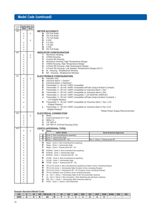
![8
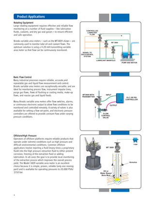
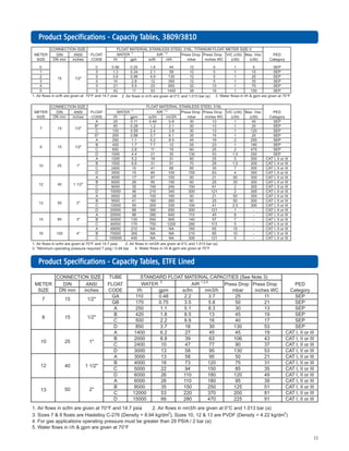
PrPrPrPrProduct Dimensions - Explosion Product Dimensions - Explosion Product Dimensions - Explosion Product Dimensions - Explosion Product Dimensions - Explosion Proof Housingoof Housingoof Housingoof Housingoof Housing
165 6.50
B
A 1.5[1/16]
D
172 6.75
C
165 6.50
B
A 1.5[1/16] 172 6.75
D
C
Model 3809 Explosion Proof Indicator Housing with
Flanged Connections mm [inches]
Model 3809 Explosion Proof Indicator Housing with
Threaded Female St'd Connections mm [inches]
* Dimensions apply to threaded female standard connections only.
Meter
Size
Connection A B C D Weight (Approx.)
0-5
7 & 8
10
12
13
1/2" Threaded Female St'd
1/2" Threaded Female St'd
1" Threaded Female St'd
1-1/2" Threaded Female St'd
2" Threaded Female St'd
225 [8.85]*
225 [8.85]*
300 [11.81]*
300 [11.81]*
300 [11.81]*
112 [4.41]
112 [4.41]
120 [4.73]
129 [5.08]
135 [5.31]
218 [8.57]
218 [8.57]
218 [8.57]
218 [8.57]
218 [8.57]
44 [1.72]
44 [1.72]
44 [1.72]
44 [1.72]
44 [1.72]
11.8 kg [26 lbs. ]
11.8 kg [26 lbs. ]
13.6 kg [30 lbs. ]
15.9 kg [35 lbs. ]
16.8 kg [37 lbs. ]
0-5
7 & 8
10
12
13
15
16
1/2" Flange
1/2" Flange
1" Flange
1-1/2" Flange
2" Flange
3" Flange
4" Flange
250 [9.84]
250 [9.84]
250 [9.84]
250 [9.84]
250 [9.84]
250 [9.84]
350 [13.78]
113 [4.45]
113 [4.45]
120 [4.73]
129 [5.08]
135 [5.31]
153 [6.02]
168 [6.61]
218 [8.57]
218 [8.57]
218 [8.57]
218 [8.57]
218 [8.57]
218 [8.57]
218 [8.57]
44 [1.72]
44 [1.72]
44 [1.72]
44 [1.72]
44 [1.72]
44 [1.72]
94 [3.69]
13.2 kg [29 lbs. ]
13.2 kg [29 lbs. ]
16.8 kg [37 lbs. ]
21.3 kg [47 lbs. ]
23.1 kg [51 lbs. ]
29.0 kg [64 lbs. ]
46.7 kg [103 lbs. ]](https://image.slidesharecdn.com/variable-area-flow-meter-data-sheet-mt3809g-mt3809elf-mt3809tfe-mt3810-170626184524/85/Metal-Tube-Variable-Area-Flow-Meter-8-320.jpg)


The Brooks MT3809 meter utilizes a variable area principle and is suitable for gas, liquid, and steam applications under high pressure and temperature conditions. It features a robust 316 stainless steel construction and offers versatile options like an LCD display, alarm functions, and various connection types for flexible installations. This meter is highly regarded for its reliability and performance in industrial applications, especially in hazardous environments.


