SlideShare a Scribd company logo
1 of 32
Download to read offline
1
Data Sheet
Brooks
Flow Controllers
Variable Area
DescriptionDescriptionDescriptionDescriptionDescription
PrPrPrPrProduct Featuroduct Featuroduct Featuroduct Featuroduct Featureseseseses
Flow Controllers for Gas & Liquid Service
Model FC 8744, Series FC 8800 & FC 8900
Model 1350G with FC 8800
DS-VA-FC-eng
October, 2015
Brooks®
flow controllers are designed to maintain a constant differential pressure across
an integral manual flow regulating valve. The incoming fluid pressure on one side of
the diaphragm, and outlet pressure plus spring action on the other side, position an
integral diaphragm-actuated control valve. Variations in the supply or discharge
pressure disturb the balance of forces on the diaphragm, causing the internal control
valve to open or close, thus maintaining a fixed differential pressure across the integral,
manual flow regulating valve resulting in constant flow. (Refer to Figure 1)
Model FC 8744Model FC 8744Model FC 8744Model FC 8744Model FC 8744 controllers are used for accurately adjusting and maintaining small gas
and liquid flows with variable downstream pressures.
Series FC 8800Series FC 8800Series FC 8800Series FC 8800Series FC 8800 controllers are used for accurately adjusting and maintaining liquid and
gas flows with variable upstream pressures.
Series FC 8900Series FC 8900Series FC 8900Series FC 8900Series FC 8900 controllers are used for accurately adjusting and maintaining liquid and
gas flows with variable downstream pressures.
• Flow controllers for high pressure or low flow rates to handle demanding applications
• Integral mounting to flowmeter to save space and improve installation
• High-resolution valves provide precise flow control for many applications
• Many different materials of construction that provides process immunity and flexibility
FC 8800/ FC 8900 FC 8744
PrPrPrPrProduct Specificationsoduct Specificationsoduct Specificationsoduct Specificationsoduct Specifications
SpecificationsSpecificationsSpecificationsSpecificationsSpecifications FC Series Flow ControllersFC Series Flow ControllersFC Series Flow ControllersFC Series Flow ControllersFC Series Flow Controllers
Flow Ranges (Refer to Table 1)Flow Ranges (Refer to Table 1)Flow Ranges (Refer to Table 1)Flow Ranges (Refer to Table 1)Flow Ranges (Refer to Table 1) Water - up to 480 GPH / 1820 l/h
Air - up to 2130 SCFH / 56000 ln
/h
Pressure and Temperature RatingsPressure and Temperature RatingsPressure and Temperature RatingsPressure and Temperature RatingsPressure and Temperature Ratings Up to 1000 psig / 69 Bar. Refer to Table 2a or 2b
Minimum Operating Temperature: -40°F/C
Maximum Operating Temprature: Refer to Tables 2a or 2b.
Pressure DropPressure DropPressure DropPressure DropPressure Drop Refer to Table 2a.
Pressure Equipment DirectivePressure Equipment DirectivePressure Equipment DirectivePressure Equipment DirectivePressure Equipment Directive (97/23/EC)(97/23/EC)(97/23/EC)(97/23/EC)(97/23/EC) Equipment falls under Sound Engineering Practice (SEP) according to the directive.
(Specifications continued on next page)
2
PrPrPrPrProduct Specifications (conoduct Specifications (conoduct Specifications (conoduct Specifications (conoduct Specifications (continued)tinued)tinued)tinued)tinued)
SpecificationsSpecificationsSpecificationsSpecificationsSpecifications FC Series Flow ControllersFC Series Flow ControllersFC Series Flow ControllersFC Series Flow ControllersFC Series Flow Controllers
Materials of ConstructionMaterials of ConstructionMaterials of ConstructionMaterials of ConstructionMaterials of Construction
Controller BodyController BodyController BodyController BodyController Body 316 Stainless Steel, Brass or Aluminum (FC 8744 only). Refer to Table 3
Controller DiaphragmController DiaphragmController DiaphragmController DiaphragmController Diaphragm Buna-N, Teflon®
or Viton®
fluoroelastomers. Refer to Table 3.
Needle ValveNeedle ValveNeedle ValveNeedle ValveNeedle Valve 316 Stainless Steel Cartridge Valve. Refer to Figure 3. Refer to data sheet DS-VA-CART-eng.
316 Stainless Steel NRSTM
Valve. Refer to Figure 2. Refer to data sheet DS-VA-8503-eng.
316 Stainless Steel high flow needle valve type. Refer to Table 3.
O-ringsO-ringsO-ringsO-ringsO-rings Viton® fluoroelastomers, Buna-N, Kalrez® (SS body only), EPR (SS body only),
Kalrez/Teflon (SS body only). Refer to Table 3.
DimensionsDimensionsDimensionsDimensionsDimensions Refer to Figure 4
SizingSizingSizingSizingSizing Refer to Table 4.
Material CertificationMaterial CertificationMaterial CertificationMaterial CertificationMaterial Certification Certification to NACE MR-01-75;
(Stainless Steel body only)(Stainless Steel body only)(Stainless Steel body only)(Stainless Steel body only)(Stainless Steel body only) Certification to EN 10204-2.2; Certification to EN 10204-3.1
Ordering Information / Model CodesOrdering Information / Model CodesOrdering Information / Model CodesOrdering Information / Model CodesOrdering Information / Model Codes Refer to Model Code
Figure 3 Cutaway View, Cartridge Valve
Figure 1 Cutaway View, Principle of Operation
Figure 2 Cutaway View, NRS Valve
3
PrPrPrPrProduct Specifications - Flow Ranges, Product Specifications - Flow Ranges, Product Specifications - Flow Ranges, Product Specifications - Flow Ranges, Product Specifications - Flow Ranges, Pressuressuressuressuressure /e /e /e /e / TTTTTemperemperemperemperemperaturaturaturaturature Ratings & Pre Ratings & Pre Ratings & Pre Ratings & Pre Ratings & Pressuressuressuressuressure Dre Dre Dre Dre Dropopopopop
Table 1 FC Series Flow Ranges
Table 2a FC Series Pressure / Temperature Ratings and Pressure Drop
Table 2b FC Series Pressure / Temperature Ratings CRN
4
PrPrPrPrProduct Specifications (conoduct Specifications (conoduct Specifications (conoduct Specifications (conoduct Specifications (continued)tinued)tinued)tinued)tinued)
Table 3 FC Series Materials of Construction / Connection / Valve Option
Table 4 Sizing Chart
5
PrPrPrPrProduct Dimensionsoduct Dimensionsoduct Dimensionsoduct Dimensionsoduct Dimensions
Figure 4 Flow Controller Dimensional Drawings
Model FC 8744
Model FC 8830
Series FC 8800/8900
6
Model CodeModel CodeModel CodeModel CodeModel Code
Code DescriptionCode DescriptionCode DescriptionCode DescriptionCode Description Code OptionCode OptionCode OptionCode OptionCode Option Option DescriptionOption DescriptionOption DescriptionOption DescriptionOption Description
I.I.I.I.I. Base Model Number FCA87FCA87FCA87FCA87FCA87 Low flow gases and liquids with variable downstream pressure
FCA88FCA88FCA88FCA88FCA88 Gases and liquids with variable upstream pressure
FCA89FCA89FCA89FCA89FCA89 Gases and liquids with variable downstream pressure
II.II.II.II.II. Type of Use 0000000000 General use, standard operating pressure, integral connection to Models 1350 & 1355
0202020202 General use, standard operating pressure, integral NPT connections
0505050505 General use, high operating pressure, integral NPT connections
1212121212 High flow rates, standard operating pressure, integral NPT connections
1515151515 High flow rates, high operating pressure, integral NPT connections
30*30*30*30*30* Very high flow rates, standard operating pressure, integral NPT connections
4040404040 Precise control, standard operating pressure, integral connection to Models 1350 & 1355
4242424242 Precise control, standard operating pressure, integral NPT connections
4545454545 Precise control, high operating pressure, integral NPT connections
44*44*44*44*44* Very precise control, low operating pressure, adapters required
III.III.III.III.III. Body Material A*A*A*A*A* Brass
BBBBB 316 Stainless Steel
C*C*C*C*C* Aluminum - FC 8744 only
DDDDD 316 Stainless Steel - CRN
IV.IV.IV.IV.IV. Diaphragm Material 11111 Viton
22222 Teflon
3*3*3*3*3* Buna
V.V.V.V.V. O-ringMaterial AAAAA Viton
BBBBB Buna
CCCCC Kalrez - Stainless Steel body only
DDDDD Kalrez/Teflon - Stainless Steel body only
EEEEE EPR - Stainless Steel body only
YYYYY Not applicable
VI.VI.VI.VI.VI. Process Connection Size & Type 11111 1/4” FNPT
22222 1/8 FNPT
33333 1/8” Tube Compression
44444 1/4” Tube Compression
5*5*5*5*5* 1/4” I. D. Hose
6*6*6*6*6* 3/4” FNPT
77777 Integral 5/16-24 UNF Thd
VII.VII.VII.VII.VII. Valve Configuration AAAAA Cartridge Valve, Low Flow
BBBBB Cartridge Valve, Medium Flow
CCCCC Cartridge Valve, High Flow
DDDDD NRS Needle Valve, Size #1 (316 SS only)
EEEEE NRS Needle Valve, Size #2 (316 SS only)
FFFFF NRS Needle Valve, Size #3 (316 SS only)
GGGGG NRS Needle Valve, Size #4 (316 SS only)
HHHHH NRS Needle Valve, Size #5 (316 SS only)
JJJJJ NRS Needle Valve, Size #6 (316 SS only)
LLLLL High Flow Needle Valve
YYYYY No Valve
VIII.VIII.VIII.VIII.VIII. Valve Option 00000 Knob only
IX.IX.IX.IX.IX. Filter AAAAA None
BBBBB Filter on Inlet
CCCCC Filters on Inlet & Outlet
X.X.X.X.X. Mounting Configuration 00000 None
11111 Mounting Bracket, Plated Steel (standard) Note: N/A FC 8744
22222 Mounting Bracket, Stainless Steel Note: N/A FC 8744
* CRN NOT AVAILABLE
Sample Standard Model Code (Fields incomplete )Sample Standard Model Code (Fields incomplete )Sample Standard Model Code (Fields incomplete )Sample Standard Model Code (Fields incomplete )Sample Standard Model Code (Fields incomplete )
IIIII IIIIIIIIII IIIIIIIIIIIIIII IVIVIVIVIV VVVVV VIVIVIVIVI VIIVIIVIIVIIVII VIIIVIIIVIIIVIIIVIII IXIXIXIXIX XXXXX XIXIXIXIXI XIIXIIXIIXIIXII
FCA88FCA88FCA88FCA88FCA88 0000000000 BBBBB 11111 AAAAA 11111 DDDDD 00000 AAAAA 00000
(Model Code continued on next page)
7
Model Code (ConModel Code (ConModel Code (ConModel Code (ConModel Code (Continued)tinued)tinued)tinued)tinued)
Sample Standard Model Code (Fields complete)Sample Standard Model Code (Fields complete)Sample Standard Model Code (Fields complete)Sample Standard Model Code (Fields complete)Sample Standard Model Code (Fields complete)
IIIII IIIIIIIIII IIIIIIIIIIIIIII IVIVIVIVIV VVVVV VIVIVIVIVI VIIVIIVIIVIIVII VIIIVIIIVIIIVIIIVIII IXIXIXIXIX XXXXX XIXIXIXIXI XIIXIIXIIXIIXII
FCA88FCA88FCA88FCA88FCA88 0000000000 BBBBB 11111 AAAAA 11111 DDDDD 00000 AAAAA 00000 AAAAA 11111
Code DescriptionCode DescriptionCode DescriptionCode DescriptionCode Description Code OptionCode OptionCode OptionCode OptionCode Option Option DescriptionOption DescriptionOption DescriptionOption DescriptionOption Description
XI.XI.XI.XI.XI. Material Certifications AAAAA None
BBBBB Certification to NACE MR-010-75
CCCCC Material Certification EN 10204-2.2
DDDDD Material Certification EN 10204-3.1
EEEEE Certification to NACE & Material Certification EN 10204-2.2
FFFFF Certification to NACE & Material Certification EN 10204-3.1
XII.XII.XII.XII.XII. Additional Cleaning 11111 Standard Cleaning Process
22222 Degrease and Clean for Oxygen Service
* CRN NOT AVAILABLE
8
BrBrBrBrBrooks Service and Supportooks Service and Supportooks Service and Supportooks Service and Supportooks Service and Support
Brooks is committed to assuring all of our customers receive the ideal flow solution for their application, along with outstanding service and
support to back it up. We operate first class repair facilities located around the world to provide rapid response and support. Each location
utilizes primary standard calibration equipment to ensure accuracy and reliability for repairs and recalibration and is certified by our local
Weights and Measures Authorities and traceable to the relevant International Standards.
Visit www.BrooksInstrument.com to locate the service location nearest to you.
STSTSTSTSTARARARARARTTTTT-UP SERVICE-UP SERVICE-UP SERVICE-UP SERVICE-UP SERVICE AND IN-SITU CALIBRAAND IN-SITU CALIBRAAND IN-SITU CALIBRAAND IN-SITU CALIBRAAND IN-SITU CALIBRATIONTIONTIONTIONTION
Brooks Instrument can provide start-up service prior to operation when required. For some process applications, where ISO-9001 Quality
Certification is important, it is mandatory to verify and/or (re)calibrate the products periodically. In many cases this service can be provided under
in-situ conditions, and the results will be traceable to the relevant international quality standards.
CUSTCUSTCUSTCUSTCUSTOMER SEMINARSOMER SEMINARSOMER SEMINARSOMER SEMINARSOMER SEMINARS ANDANDANDANDAND TRAININGTRAININGTRAININGTRAININGTRAINING
Brooks Instrument can provide customer seminars and dedicated training to engineers, end users, and maintenance persons.
Please contact your nearest sales representative for more details.
HELP DESKHELP DESKHELP DESKHELP DESKHELP DESK
In case you need technical assistance:
Americas 1 888 554 FLOW
Europe +31 (0) 318 549 290
Asia +81 3 (0) 5633 7100
Due to Brooks Instrument's commitment to continuous improvement of our products, all specifications are subject to change without notice.
TRADEMARKS
Brooks ............................................................. Brooks Instrument, LLC
All other trademarks are the property of their respective owners.
1
The Brooks®
SolidSense II®
Pressure Transducers are designed for stable, accurate, and
reliable pressure monitoring in high purity and ultra-high purity (UHP) applications. A
combination of optimum design and materials improves both signal stability and
reliability in numerous pressure measurement applications.
Pressure transducers are widely used in high purity and ultra-high purity fluid storage
and delivery systems in many industries. Unfortunately, a number of current transducers
rely on technologies that have problems with zero and span drift, thermal shift, and case
stress. Adjusting the transducer to rectify errors requires ongoing maintenance that
increases downtime and cost of ownership.
The third generation SolidSense II pressure transducers by Brooks Instrument utilize
glass-fused strain gauge technology enabling a new level of performance for micro
electronics and industrial applications.
SolidSense II pressure transducers employ ultra stable, micro machined silicon strain
gauges that are matched and fused to the metal diaphragm at high temperature to
relieve manufacturing induced stress. The process reduces drift or lack of zero stability
commonly associated with competitive products. Consequently, down time for zero
adjustment to compensate for drift is significantly reduced. In addition, the unique
mechanical design eliminates torque effects during installation.
SolidSense II digital architecture enables automated software driven calibration and a
wide range of thermal compensation routines, unlike the passive compensation used in
competitive devices. This enhances measurement repeatability regardless of changes to
the operational environment.
SolidSense II devices feature 316L stainless steel wetted surfaces electropolished to
5- and 10-micro in. (5- and 10-Ra) to maintain the purity of the measured fluid.
Data Sheet
Pressure Transducers
OverviewOverviewOverviewOverviewOverview
Superior stability and reliability
for demanding pressure
measurement applications
SolidSense II®
Pressure Transducers
SolidSense II®
Pressure
Transducers
DS-PR-SolidSenseII-PT-eng
April, 2016
2
PrPrPrPrProduct Descriptionoduct Descriptionoduct Descriptionoduct Descriptionoduct Description
Industry StandarIndustry StandarIndustry StandarIndustry StandarIndustry Standard Ind Ind Ind Ind Interfaceterfaceterfaceterfaceterface
Options and outputs
DigitalDigitalDigitalDigitalDigital ThermalThermalThermalThermalThermal
CompensationCompensationCompensationCompensationCompensation
Multi-point temperature
compensation
Digital LinearizationDigital LinearizationDigital LinearizationDigital LinearizationDigital Linearization
Consistency of performance
StrStrStrStrStress Isolation Stageess Isolation Stageess Isolation Stageess Isolation Stageess Isolation Stage
To reduce stress introduced
during mounting
SensorSensorSensorSensorSensor AAAAAttacttacttacttacttachmenhmenhmenhmenhmenttttt
Glass fusion bonding
to relieve stress
Sensor ConstructionSensor ConstructionSensor ConstructionSensor ConstructionSensor Construction
Paired strain gauges to reduce
stress induced drift
WWWWWetted Materialsetted Materialsetted Materialsetted Materialsetted Materials
316L meets SEMI F20Fully Swept FlowpathFully Swept FlowpathFully Swept FlowpathFully Swept FlowpathFully Swept Flowpath
Complete removal of
residual gas
FeaturFeaturFeaturFeaturFeatureseseseses BenefitsBenefitsBenefitsBenefitsBenefits
Two pairs of strain gauge sensors Precision matched sensors for improved performance
Glass fusion process to High temperature glass bonding drives off any mechanically induced build up of stress
bond strain gauge from sensor manufacturing process
Stress isolation stage Minimizes stress introduced during installation of the transducer
Digital temperature compensation Improved thermal stability over entire range of temperature
Digital linearization and calibration Consistency of performance, improved reproducibility
Fully swept flowpath Ensures contamination-free pressure measurement
Integrated fully rotatable display option Local indication of process pressure for safe system maintenance
Compact with no special wiring for easy system integration/installation
3
Sensor ConstructionSensor ConstructionSensor ConstructionSensor ConstructionSensor Construction
SolidSense II utilizes proprietary micro machined silicon strain
gauges that are ultra stable and suitable for high purity and
ultra-high purity requirements.
A design feature for controlling stress is the use of dual paired
gauges. By using two paired gauges in Wheatstone bridge
circuitry, pressure signal is maximized enhancing stability.
Sensor AttachmentSensor AttachmentSensor AttachmentSensor AttachmentSensor Attachment
A key step for eliminating machining stress in the diaphragm is
the glass fusion process used to bond the strain gauges to the
sensor diaphragm. This process occurs at 600O
C and drives off
any mechanically induced build up of stress resulting in a
highly stable and accurate sensor.
By using silicon strain gauge technology and the glass fusion
bonding method for SolidSense II, there is no stress induced
from thermal gradients between structural materials. In some
competitive designs, different thermal expansion coefficients
between the metal casing and ceramic electrode (upon which
the sensor is mounted) allow for flexing of the sensor which is
interpreted as a false pressure change.
Stress Isolation StageStress Isolation StageStress Isolation StageStress Isolation StageStress Isolation Stage
SolidSense II incorporates an isolation stage shown at right that
minimizes stress from: (1) thermal heating during any adjacent
welding and (2) torque during installation in gas panels, gas
interface boxes, valve manifold boxes, etc. By preventing stress
during these two scenarios, creep (drift) is eliminated during
subsequent usage.
Wetted MaterialsWetted MaterialsWetted MaterialsWetted MaterialsWetted Materials
Made from 316L that meets SEMI F20. Surface finish complies
with SEMI F19. Product is assembled in clean environment
compliant with ASTM F1374-92 - meets requirement for ultra-
high purity application.
PrPrPrPrProduct Descriptionoduct Descriptionoduct Descriptionoduct Descriptionoduct Description
Ground
VIn
5V
R1, Tension R2, Comp.
R3, Comp. R4, Tension
Pressure
Tension CompressionCompression
Stress
Isolation
Groove
Diaphragm
Strain Gauges
(bonded on
diaphragm)
Reference
Volume
Fully rotatable displayFully rotatable displayFully rotatable displayFully rotatable displayFully rotatable display
This integrated display option reduces gas panel overall size
constraints by eliminating the requirement for a standalone
pressure gauge and reduces height by 2-6 inches. The display is
fully rotatable - covering 4 quadrants - and no tools are required
to set/secure the position. A bright LED display ensures readability
in typical compact installation conditions. It provides exact visual
feedback and verification of line pressure and an over pressure
indication (roughly at 110% FS). The fully integrated display
combined with the SSII high performance provides exact pressure
measurement choice for field upgrades and new gas processing
system designs.
4
Digital Linearization and CalibrationDigital Linearization and CalibrationDigital Linearization and CalibrationDigital Linearization and CalibrationDigital Linearization and Calibration
SolidSense II is calibrated with automated software which uses
about 200 linearization points compared with 2 for some
competing units. This results in consistency of performance
from one transducer to the next (reproducibility). Due to
automation, operator induced differences are eliminated.
Digital Thermal CompensationDigital Thermal CompensationDigital Thermal CompensationDigital Thermal CompensationDigital Thermal Compensation
SolidSense II uses multi-point digital temperature compensation. Some competitive devices rely on single or two point
compensation to optimize device performance over the operating temperature range. For example, device performance might be
checked at -10o
C and 60o
C to determine the dZ/dT and dS/dT (rate of zero/span change per temperature change) with the
temperature compensation interpolated for other values. SolidSense II can incorporate five separate data points, which are typically
taken at -10o
C, -5o
C, 20o
C, 40o
C and 60o
C, giving the temperature compensation algorithm far better resolution.
Fully swept flowpathFully swept flowpathFully swept flowpathFully swept flowpathFully swept flowpath
The SolidSense II incorporates an all-swept flowpath and very small internal volume allowing complete removal of residual fluid
during the purge cycle. As a result inert, dry and clean surfaces are available at the end of the purge cycle.
ASTM F1397 establishes a dry-down requirement to 20 ppbv H20 within 30 minutes. As accompanying data shows, the dead end
configuration of the SolidSense II recovered to desired level within 11.5 minutes and the flow thru configuration recovered in 9.5
minutes, both well below the requirement indicated in standard.
PrPrPrPrProduct Descriptionoduct Descriptionoduct Descriptionoduct Descriptionoduct Description
Pulse Test Dry Down SolidSense-II Transducer
GFD01A3DCS Model
-50
0
50
100
150
200
250
300
350
400
450
0 5 10 15 20 25
Time (min)
Water(ppb)
Water Contribution Surface Mount Spool Piece
Water Contribution Surface Mount Transducer
Subtracted
Pulse Test Dry Down SolidSense-II Transducer
GFF01A30FS Model
-100
-50
0
50
100
150
200
250
300
350
400
0 5 10 15 20 25
Time (min)
Water(ppb)
Water Contribution VCR Spool Piece
Water Contribution VCR Mount Transducer
Subtracted
Thermal Zero
0.07
(0.23)(0.22)
(0.04)
(0.18)
(0.45)
(1.00)
2.68
2.86
0.57
0.52
(1.00)
(0.50)
‐
0.50
1.00
1.50
2.00
2.50
3.00
‐30 ‐20 ‐10 0 10 20 30 40 50 60 70
Temperature (deg C)
ZeroDeviation(%FS/100degF)
Brooks 1
Brooks 2
Comp A 1
Comp A 2
Comp B 1
Comp B 2
Thermal Span
(0.14)
0.020.10
0.29
(0.66)
(0.44)
1.83
(2.07)
1.43
0.76
0.91
(2.01)
(2.50)
(2.00)
(1.50)
(1.00)
(0.50)
‐
0.50
1.00
1.50
2.00
‐25 ‐5 15 35 55 75
Temperature (deg C)
ZeroDeviation(%FS/100degF)
Brooks 1
Brooks 2
Comp A1
Comp A2
Comp B1
Comp B2
5
RobustnessRobustnessRobustnessRobustnessRobustness
The SolidSense II design incorporates a stress isolation stage. This prevents stresses built up during installation of transducers from
being transmitted to diaphragm. As a result, SolidSense II will not require frequent resetting of zero after installation and in
operation.
A number of applications involve subjecting the pressure transducer to rapid pressure cycling in a purge cycle. As shown in test
results, SolidSense II will not temporarily indicate inaccurate pressure readings due to the Joule-Thompson effect. In some
competitive devices this may cause false alarms and shut down the gas distribution system.
PrPrPrPrProduct Descriptionoduct Descriptionoduct Descriptionoduct Descriptionoduct Description
Zero StabilityZero StabilityZero StabilityZero StabilityZero Stability
Minimal drift, creep and shifts during installation and service life.
Stabilty - 2,000,000 pressure cycles without failure
MetrologyMetrologyMetrologyMetrologyMetrology
Calibration system that is traceable to international primary standards with minimal uncertainty - precise dependable pressure
measurements.
Accurate pressure readings during purge cycle
Solid Sense II Pressure Cycle (0 psig - 2000 psig)
3000 psig device (0-5Vdc output)
0.0
0.5
1.0
1.5
2.0
2.5
3.0
3.5
4.0
4.5
52:39 53:46 54:59 56:12 57:25 58:38 59:51
Time (minutes)
TransducerOutput(VDC)
6
PrPrPrPrProductoductoductoductoduct ApplicationsApplicationsApplicationsApplicationsApplications
Semiconductor ManufacturingSemiconductor ManufacturingSemiconductor ManufacturingSemiconductor ManufacturingSemiconductor Manufacturing
Ultra-high purity gases and liquids are at the heart of
semiconductor manufacturing operations. Their safe storage
and distribution is vital to uninterrupted production. Gas
cabinets, gas panels, valve manifold boxes and distribution
valve boxes all require reliable pressure measurement of these
fluids.
Several design features and manufacturing processes described
in more detail elsewhere in this data sheet enable superior
accuracy and long-term stability. Two are emphasized here:
The sensor isolation stage minimizes stress coupled from
adjacent welding operations and torque from installation. By
isolating stress during these two scenarios, stress-related creep
or drift is eliminated.
All gas cabinets are designed to handle purge cycles to
facilitate safe changeover of cylinders. Whether these are
automatic or manual, it is common to introduce a big surge in
pressure followed by vacuum over very short period of time.
Test results show that SolidSense II will not temporarily indicate
inaccurate readings during purge cycles due to Joule-Thompson
effect.
7
PrPrPrPrProductoductoductoductoduct ApplicationsApplicationsApplicationsApplicationsApplications
Measure build-up across filtersMeasure build-up across filtersMeasure build-up across filtersMeasure build-up across filtersMeasure build-up across filters
Many sanitary processes use filters to ensure product quality. As
the load on the filter increases, a pressure differential between
the inlet and outlet sides of the filter can be measured using
SolidSense II. Once an established differential limit is reached,
the filter can be preventively replaced before throughput goes
down.
8
PrPrPrPrProduct Specificationsoduct Specificationsoduct Specificationsoduct Specificationsoduct Specifications
PerformancePerformancePerformancePerformancePerformance Non-Display VersionNon-Display VersionNon-Display VersionNon-Display VersionNon-Display Version Display VersionDisplay VersionDisplay VersionDisplay VersionDisplay Version
Temperature:
Operating: -20O
F to 180O
F (-29O
C to 82O
C) -20°F to 140°F (-29°C to 60°C)
Storage: -40O
F to 180O
F (-40O
C to 82O
C) -40°F to 167°F (-40°C to 75°C)
Compensated: -4O
F to 140O
F (-20O
C to 60O
C) / 68O
F to 140O
F (20O
C to 60O
C) 0-10 Vdc version
Burst Pressure: 400% full scale
Proof Pressure: 200% full scale up to 2,000 psi, 150% full scale for higher ranges
Accuracy: 0.25% full scale (BFSL)
Response Time: < 5 msec
Zero and Span Temperature
Coefficient (each):
>100 PSI Ranges Full Scale: +0.02% full scale/O
F (-4O
F to 140O
F, -20O
C to 60O
C)
+0.50% full scale (68O
F to 140O
F, 20O
C to 60O
C) 0 to 10 Vdc version
<100 PSI Ranges Full Scale: +0.04% full scale/O
F (-4O
F to 140O
F, -20O
C to 60O
C)
+1.00% full scale (68O
F to 140O
F, 20O
C to 60O
C) 0 to 10 Vdc version
MechanicalMechanicalMechanicalMechanicalMechanical
Housing: Stainless steel, polymer plastics
Wetted Parts: VIM-VAR 316L stainless steel, SEMI F20
Surface Finish: Compliant with SEMI F19
Cleanliness: Compliant to ASTM F1374-92 (2005)
Internal Volume: 1.79cc
Process Connections: (See Product Configurations for available options)
Approximate Shipping Weight: 0.70 lb. (0.32 kg)
ElectricalElectricalElectricalElectricalElectrical Non-Display VersionNon-Display VersionNon-Display VersionNon-Display VersionNon-Display Version Display VersionDisplay VersionDisplay VersionDisplay VersionDisplay Version
Supply Current: Max. 10 mA Max. 30 mA
Power Requirements: 10 to 30 Vdc for 4 to 20 mA output 15 to 30 Vdc for 4 to 20 mA output and no signal output
11 to 30 Vdc for 0 to 5 Vdc output 11 to 30 Vdc for 0 to 5 Vdc output
13 to 32 Vdc for 0 to 10 Vdc output 13 to 30 Vdc for 0 to 10 Vdc output
Electrical Connections: Code B Bendix®
connector
(See page 11 for Code P Pigtail 6 ft long
full list) Code D 15-pin HD D-sub connector
Code K 9-pin D-sub
Code A 4 ft pigtail with AMP®
connector (3 pin)
Code G 4 ft pigtail with AMP®
connector (4 pin)
Code H 6 inch pigtail with Molex®
connector
Electrical Protection: Reverse polarity for power connections
Optional DisplayOptional DisplayOptional DisplayOptional DisplayOptional Display
Digits: N/A -xxx to 1xxx
Type: N/A 7 Segment Red LED
Polarity: N/A Automatic (-) Display
Over Pressure Reading Trigger: N/A 110% full scale ± 5% full scale (Display reading: 1---)
Display Accuracy: N/A ±-0.25% of Rdg ± 1 Count for psi
(excluding transducer output) N/A ± - 0.25% of Rdg ± 5 Count for kPa
Character Size: N/A 0.30” height
kPa/psi Switch: N/A Yes
Rotatable: N/A Continuous rotation covering 4 quadrants
Zero Pot: N/A Yes
Zero Pot Adj. Screwdriver: N/A 1-1.2 mm flat type
Approvals and ComplianceApprovals and ComplianceApprovals and ComplianceApprovals and ComplianceApprovals and Compliance
FM Approval: Non-Incendive for use in Class I, Div II Groups A, B, C and D Hazardous Applications
Excludes 0 to 10 Vdc and 15-pin HD D-Sub connector configurations, GI/integrated display pending
EMC: Compliant to EU Directive 2004/108/EC
RoHS: Compliant to EU Directive 2002/95/EC
9
PrPrPrPrProduct Dimensions (Standaroduct Dimensions (Standaroduct Dimensions (Standaroduct Dimensions (Standaroduct Dimensions (Standard Cond Cond Cond Cond Configurfigurfigurfigurfigurations)ations)ations)ations)ations)
Shown are just a few of the most common configurations of the SolidSense II®
pressure transducers.
The SolidSense II pressure transducers are available in over 40 configurations.
For more information and a complete selection of configurations available see the Brooks Instrument Installation and Operation Manual
“XXXXX-PR-PR-PR-PR-PR-SolidSense II-PT-SolidSense II-PT-SolidSense II-PT-SolidSense II-PT-SolidSense II-PT-eng-eng-eng-eng-eng” by visiting our website at www.BrooksInstrument.com or contact your nearest Brooks customer service
representative for assistance.
NO. 4
VCR SWIVEL FEMALE PIGTAIL
GFDXXXXPSF
FITTING A333124002
CABLE ME0521302-001
PIGTAIL
.84 [21.33]
3.40 [86.36]
PIGTAIL
NO. 4
VCR SWIVEL MALE PIGTAIL
GFDXXXXPSM
FITTING A333124001
CABLE ME0521302-001
.84 [21.33]
4.00 [101.6]
W-SEAL Pigtail
GFDXXXXP5W
FITTING A333366001
1.53 [38.97]
3.88 [98.55]
.84 [21.33]
CABLE ME0521302-001
PIGTAIL
.84 [21.33]
VCR FIXED MALE
THRUTUBE PIGTAIL
GFFXXXXPVM
FITTING A333125004
2.24 [56.90]
3.36 [85.40]
CABLE ME0521302-001
BENDIX
TUBE STUB/TUBE STUB
THRUTUBE BENDIX
GFFXXXXB4T
FITTING A333125001
.84 [21.33]
1.85 [46.98]
3.23 [82.04]
.31 [7.92]
2X .42 [10.79]
2X .25 [6.35]
TUBE STUB/TUBE STUB
THRUTUBE PIGTAIL
GFFXXXXP4T
FITTING A333125001
PIGTAIL
1.85 [46.98]
.84 [21.33]
3.36 [85.40]
.31 [7.92]
2X .42 [10.79]
2X .25 [6.35]
CABLE ME0521302-001
VCR SWIVEL FEMALE BENDIX
GFDXXXXBSF
FITTING A333124002
NO. 4
BENDIX
.84 [21.33]
3.30 [83.86]
1 1/8" C-SEAL W/AMP ON PIGTAIL
GFDXXXXMCS
FITTING A333127001
CABLE ME0521302-001
.84 [21.33]
1.12 [28.57]
3.51 [89.15]
PIGTAIL
VCR SWIVEL MALE BENDIX
GFDXXXXBSM
FITTING A333124001
BENDIX
NO. 4
.84 [21.33]
3.89 [98.84]
10
Optional CablesOptional CablesOptional CablesOptional CablesOptional Cables AAAAAvailable for the SolidSense II Prvailable for the SolidSense II Prvailable for the SolidSense II Prvailable for the SolidSense II Prvailable for the SolidSense II Pressuressuressuressuressureeeee TTTTTrrrrransducersansducersansducersansducersansducers
CableCableCableCableCable CableCableCableCableCable Transducer ElectricalTransducer ElectricalTransducer ElectricalTransducer ElectricalTransducer Electrical TransducerTransducerTransducerTransducerTransducer
Part NumberPart NumberPart NumberPart NumberPart Number DescriptionDescriptionDescriptionDescriptionDescription Cable lengthCable lengthCable lengthCable lengthCable length Connector RequiredConnector RequiredConnector RequiredConnector RequiredConnector Required OutputOutputOutputOutputOutput
EL0001965104 Cable w/ four pin female Bendix connector to connect to transducer;
flying leads on opposite end for power connection 10ft. 4 pin male Bendix 4-20 mA
EL0001965105 Cable w/ four pin female Bendix connector to connect to transducer;
flying leads on opposite end for power connection 25ft. 4 pin male Bendix 4-20 mA
PrPrPrPrProduct Dimensions (Optional Display LR056)oduct Dimensions (Optional Display LR056)oduct Dimensions (Optional Display LR056)oduct Dimensions (Optional Display LR056)oduct Dimensions (Optional Display LR056)
The SolidSense II pressure transducer is available with an optional display: Model LR056, for details on this display
see DS-PR-LR056-eng
Visit the Brooks Instrument website for product documentation at: www.BrooksInstrument.com/Manuals.
LR056
Pressure
Transducer
Display
Dimensions
Local display option for SolidSense II with Bendix connector and 4-20 mA output
9999
PrPrPrPrProduct Dimensions (GID/GIF Options)oduct Dimensions (GID/GIF Options)oduct Dimensions (GID/GIF Options)oduct Dimensions (GID/GIF Options)oduct Dimensions (GID/GIF Options)
11
Model CodeModel CodeModel CodeModel CodeModel Code
SampleSampleSampleSampleSample
Model CodeModel CodeModel CodeModel CodeModel Code
Code DescriptionCode DescriptionCode DescriptionCode DescriptionCode Description Code OptionCode OptionCode OptionCode OptionCode Option Option DescriptionOption DescriptionOption DescriptionOption DescriptionOption Description
I.I.I.I.I. Base Model Code GFGFGFGFGF Pressure Transducer
GIGIGIGIGI Pressure Transducer with integrated display
II.II.II.II.II. Body Type DDDDD Dead End
FFFFF Flow Through
III.III.III.III.III. PSI 0000000000 30
0101010101 100
0202020202 250
X2X2X2X2X2 235
0505050505 500
1010101010 1000
2525252525 2500
3030303030 3000
4545454545 45
6060606060 60
1515151515 1500 Torr
IV.IV.IV.IV.IV. Pressure Reference AAAAA Absolute, psi
CCCCC Compound, psi
GGGGG Gauge, psi
EEEEE Absolute, mPa/kPa
RRRRR Compound, mPa/kPa
DDDDD Gauge, mPa/kPa
BBBBB Absolute, Bar
PPPPP Compound, Bar
SSSSS Gauge, Bar
TTTTT Absolute Torr
V.V.V.V.V. Output 33333 0.00 to 10.00 Vdc
44444 4 to 20 mA
55555 0.05 to 5.05 Vdc
66666 0.2 to 5.2 Vdc
77777 2 to 10 Vdc
88888 No signal output (GI model with display only)
VI.VI.VI.VI.VI. Electrical Connection BBBBB Bendix®
Connector
PPPPP 6 ft (2m) Pigtail
DDDDD 15 Pin HD D-Sub Connector
EEEEE 9 inch Pigtail with 15 Pin (Standard) D-Sub Connector
M+M+M+M+M+ 5 inch (0.127m) Pigtail with AMP®
Connector (4-pin)
JJJJJ Bendix®
with Jumper B-D (Offered with 4-20 mA only)
LLLLL 10 ft (3m) Pigtail
RRRRR 8 inch Pigtail with AMP®
Connector (4-pin)
NNNNN 16.5 ft cable with Bendix®
Type (Bayonet)
V+V+V+V+V+ 18 inch Pigtail with 6-pin Molex®
Connector
CCCCC 6 ft (2m) Pigtail with 9-pin D Connector
G+G+G+G+G+ 4 ft Pigtail with AMP®
Connector (4-pin)
H+H+H+H+H+ 6 inch Pigtail with Molex®
Connector
KKKKK 9-pin D-Sub
A+A+A+A+A+ 4 ft Pigtail with AMP®
Connector (3-pin)
F+F+F+F+F+ 8 inch Pigtail with AMP®
Connector (3-pin)
Q+Q+Q+Q+Q+ M12 4-pin Male Connector
SSSSS 2m (79”) Pigtail with 9-Pin D Connector
Z+Z+Z+Z+Z+ 36 inch Pigtail ith Bendix®
Connector (Bayonet)
VII.VII.VII.VII.VII. Fittings 4S4S4S4S4S Tube Weld Stub 1/4” O.D. (GFD Only)*
CS+CS+CS+CS+CS+ Surface Mount, 1.125” C-Seal, Standard (GFD & GID Only)
CHCHCHCHCH Surface Mount, 1.5” C-Seal, High Flow K1H (GFD Only)
SCSCSCSCSC Surface Mount, 1.5” C-Seal (GFD Only)
5W5W5W5W5W Surface Mount, 1.5” W-Seal (GFD Only)
4W4W4W4W4W Surface Mount, 1.125” W-Seal (GFD Only)
CD+CD+CD+CD+CD+ Surface Mount, 1.125” C-Seal, 0.5” longer gland (GFD & GID Only)
NTNTNTNTNT 1/4” NPT (GFD only)
VM+VM+VM+VM+VM+ Face Seal, fixed male (x2 on Duncan T for GFF) (GFF & GIF Only)
VSVSVSVSVS Face Seal, fixed male/swivel female on Duncan T (GFF Only)
SM+SM+SM+SM+SM+ Face Seal, swivel male (x2 on Duncan T for GFF)
SFSFSFSFSF Face Seal, swivel female (x2 on Duncan T for GFF)
4T4T4T4T4T Duncan T, 1/4” Tube Weld Stub (GFF Only)*
3T3T3T3T3T Duncan T, 3/8” Tube Weld Stub (GFF Only)*
3M3M3M3M3M Duncan T, 3/8” with Face Seal, swivel male (GFF Only)
2T2T2T2T2T Duncan T, 1/2” Tube Weld Stub (GFF Only)*
CTCTCTCTCT Tube Stub, 3/8” OD (Suitable for compression joint) (x2 on Union T for GFF)(GFD & GFF)
VIII.VIII.VIII.VIII.VIII. Special Option RRRRR Integrated Display Removed (For base model GI only)
* Tube stubs (4S, 4T, 3T and 2T) are not suitable for compression joint. Use CT for compression joint.
GID/GIF Integrated Display options are only available with the fittings and connectors noted with “+”.
IIIII IIIIIIIIII IIIIIIIIIIIIIII IVIVIVIVIV VVVVV VIVIVIVIVI VIIVIIVIIVIIVII VIIIVIIIVIIIVIIIVIII
GFGFGFGFGF FFFFF 0202020202 CCCCC 44444 PPPPP SFSFSFSFSF
12
BrBrBrBrBrooks Service and Supportooks Service and Supportooks Service and Supportooks Service and Supportooks Service and Support
TRADEMARKS
AMP ......................................................................................... Tyco Electronics
Bendix ..................................................................................... Amphenol Corp.
Brooks ........................................................................... Brooks Instrument, LLC
Molex ............................................................................................... Molex Inc.
SolidSense II .................................................................. Brooks Instrument, LLC
Brooks is committed to assuring all of our customers receive the ideal flow solution for their application, along with outstanding
service and support to back it up. We operate first class repair facilities located around the world to provide rapid response and
support. Each location utilizes primary standard calibration equipment to ensure accuracy and reliability for repairs and
recalibration and is certified by our local Weights and Measures Authorities and traceable to the relevant International Standards.
Visit www.BrooksInstrument.com to locate the service location nearest to you.
STSTSTSTSTARARARARARTTTTT-UP SERVICE-UP SERVICE-UP SERVICE-UP SERVICE-UP SERVICE AND IN-SITU CALIBRAAND IN-SITU CALIBRAAND IN-SITU CALIBRAAND IN-SITU CALIBRAAND IN-SITU CALIBRATIONTIONTIONTIONTION
Brooks Instrument can provide start-up service prior to operation when required. For some process applications, where ISO-9001
Quality Certification is important, it is mandatory to verify and/or (re)calibrate the products periodically. In many cases this service
can be provided under in-situ conditions, and the results will be traceable to the relevant international quality standards.
CUSTCUSTCUSTCUSTCUSTOMER SEMINARSOMER SEMINARSOMER SEMINARSOMER SEMINARSOMER SEMINARS ANDANDANDANDAND TRAININGTRAININGTRAININGTRAININGTRAINING
Brooks Instrument can provide customer seminars and dedicated training to engineers, end users, and maintenance persons.
Please contact your nearest sales representative for more details.
HELP DESKHELP DESKHELP DESKHELP DESKHELP DESK
In case you need technical assistance:
Americas 1 888 554 FLOW
Europe +31 (0) 318 549 290
Asia +81 (0) 3 5633 7100
Due to Brooks Instrument's commitment to continuous improvement of our products, all specifications are subject to change without notice.
1
The Brooks®
Sho-RateTM
Series glass tube variable area flow meter has been the industry
standard glass tube variable area meter for decades. This glass tube meter is ideal for a
variety of gas and liquid applications. These meters are particularly suited for purge
applications. The base configuration uses a borosilicate glass tube installed in an
aluminum frame with 316SS end blocks, adaptors, and valve. Additional material
options, valve options, and flow controllers are available to provide the appropriate
configuration for a wide variety of applications.
• Standard direct read scales on tube for all fluids and fluid conditions (user selected)
• Standard millimeter scales with flow curves for all fluids and fluid conditions (user
selected)
• Scale length (approximate) 65mm, 150mm
• Magnifier built into front shield
• Flowmeter options:
Multiple fitting adapters for all world areas
No valve, cartridge valve and precision control valve
Inlet & outlet valves
Integral flow controller, upstream & downstream
Multiple connection fittings to fit all applications
Multiple approval certifications for world wide usage
Data Sheet
Sho-RateTM
Models 1350G & 1355G
Variable Area
OverviewOverviewOverviewOverviewOverview
PrPrPrPrProduct Featuroduct Featuroduct Featuroduct Featuroduct Featureseseseses
DS-VA-1350G-eng
April, 2016
Sho-RateTM
1350G & 1355G Series
Low Flow Glass Tube
Flowmeters
2
FeaturFeaturFeaturFeaturFeatures and Benefitses and Benefitses and Benefitses and Benefitses and Benefits
OptionalOptionalOptionalOptionalOptional VVVVValves for Inlet or Outletalves for Inlet or Outletalves for Inlet or Outletalves for Inlet or Outletalves for Inlet or Outlet
• Cartridge III Valves
• NRSTM
(Non-Rising Stem)
• Integral Flow Controllers
ThrThrThrThrThreadedeadedeadedeadedeaded JacJacJacJacJack Scrk Scrk Scrk Scrk Screwewewewew
• Tubes sealed on compression gasket
MeteringMeteringMeteringMeteringMetering TTTTTubesubesubesubesubes
• Heavy-wall, precision bore
• Borosilicate glass
• Removeable without
disconnnecting instrument
InInInInInterterterterterccccchangeablehangeablehangeablehangeablehangeable TTTTTubes and Floatsubes and Floatsubes and Floatsubes and Floatsubes and Floats
with Dirwith Dirwith Dirwith Dirwith Direct Reading (DR) Scales onect Reading (DR) Scales onect Reading (DR) Scales onect Reading (DR) Scales onect Reading (DR) Scales on
thethethethethe TTTTTubeubeubeubeube
• Allows users to change ranges as
the application dictates
• DR Scale on Tube is determined
by the user; based on specific
application needs
• Eliminates reading errors
introduced by detached scales;
resulting in a more accurate
indication of flow
Rugged, Single Piece FrRugged, Single Piece FrRugged, Single Piece FrRugged, Single Piece FrRugged, Single Piece Frame Constructioname Constructioname Constructioname Constructioname Construction
InInInInIntegrtegrtegrtegrtegral Float Stopsal Float Stopsal Float Stopsal Float Stopsal Float Stops
• Prevent loss of float during tube
removal
Clear PClear PClear PClear PClear Polycarbonateolycarbonateolycarbonateolycarbonateolycarbonate
FFFFFaceshieldaceshieldaceshieldaceshieldaceshield
• Built-in magnifier for easier
float and scale reading
SelfSelfSelfSelfSelf Aligning BlocAligning BlocAligning BlocAligning BlocAligning Blocksksksksks
• Allows for easier tube alignment and
replacement
3
1350G1350G1350G1350G1350G 1355G1355G1355G1355G1355G
PrPrPrPrProduct Specificationsoduct Specificationsoduct Specificationsoduct Specificationsoduct Specifications
PerformancePerformancePerformancePerformancePerformance
AccuracyAccuracyAccuracyAccuracyAccuracy ±5% at reference conditions ± 3% at reference conditions
RepeatabilityRepeatabilityRepeatabilityRepeatabilityRepeatability 0.25% F.S.
Pressure/TemperaturePressure/TemperaturePressure/TemperaturePressure/TemperaturePressure/Temperature 200 psig (33°F - 250°F) / 13.8 bar (1°C-121°C)
Materials of ConstructionMaterials of ConstructionMaterials of ConstructionMaterials of ConstructionMaterials of Construction Borosilicate glass, Brass, Aluminum, 316 Stainless Steel, Clear Polycarbonate,
Milk White Polycarbonate, Teflon®
End Block OptionsEnd Block OptionsEnd Block OptionsEnd Block OptionsEnd Block Options Stainless Steel and Brass
Elastomer SealsElastomer SealsElastomer SealsElastomer SealsElastomer Seals Viton®
fluoroelastomers, Teflon®
, Buna, Kalrez®
perfluoroelastomers
Float MaterialsFloat MaterialsFloat MaterialsFloat MaterialsFloat Materials Glass, Sapphire, Stainless Steel, Carboloy®
, Tantalum
Connection MaterialsConnection MaterialsConnection MaterialsConnection MaterialsConnection Materials Stainless Steel
Connection OptionsConnection OptionsConnection OptionsConnection OptionsConnection Options 1/8” NPT (w/wo locknuts)
1/4” NPT (w/wo locknuts)
1/8” Compression (w/wo locknuts)
1/4” Compression (w/wo locknuts)
6 mm Compression (w/wo locknuts)
1/4” RC (w/wo locknuts)
3/8” RC (w/wo locknuts)
1/4” VCR®
1/4” ID Hose
Swagelok®
Converters
DimensionsDimensionsDimensionsDimensionsDimensions See Dimension Drawings
Alarm AvailabilityAlarm AvailabilityAlarm AvailabilityAlarm AvailabilityAlarm Availability (coming soon)
Valve OptionsValve OptionsValve OptionsValve OptionsValve Options Cartridge III Valve and NRSTM
Valve MaterialsValve MaterialsValve MaterialsValve MaterialsValve Materials Stainless Steel
Flow ControllerFlow ControllerFlow ControllerFlow ControllerFlow Controller Yes
CertificationsCertificationsCertificationsCertificationsCertifications International Calibration Certificate (ICC)
CRN
Pressure Equipment Directive (97/23/EC)
RoHS (II)
REACH (coming soon)
Materials (2.2)
4
PrPrPrPrProduct Specifications - Capacities; 1350G, Rib Guided, Spherical Floatsoduct Specifications - Capacities; 1350G, Rib Guided, Spherical Floatsoduct Specifications - Capacities; 1350G, Rib Guided, Spherical Floatsoduct Specifications - Capacities; 1350G, Rib Guided, Spherical Floatsoduct Specifications - Capacities; 1350G, Rib Guided, Spherical Floats
Models 1350G/1355GModels 1350G/1355GModels 1350G/1355GModels 1350G/1355GModels 1350G/1355G TTTTTube and Float Code; Decaled Scale Option, 7th, 8th & 9th Digitsube and Float Code; Decaled Scale Option, 7th, 8th & 9th Digitsube and Float Code; Decaled Scale Option, 7th, 8th & 9th Digitsube and Float Code; Decaled Scale Option, 7th, 8th & 9th Digitsube and Float Code; Decaled Scale Option, 7th, 8th & 9th Digits
SevenSevenSevenSevenSeventh Digit in Model Code, for Scale Conth Digit in Model Code, for Scale Conth Digit in Model Code, for Scale Conth Digit in Model Code, for Scale Conth Digit in Model Code, for Scale Configurfigurfigurfigurfigurationationationationation
CodeCodeCodeCodeCode Model 1350Model 1350Model 1350Model 1350Model 1350 TTTTTubeubeubeubeube Model 1355Model 1355Model 1355Model 1355Model 1355 TTTTTubeubeubeubeube
A R-2-15-A G
B R-2-15-B G
C R-2-15-C G
D R-2-15-D G
F R-6-15-B G
G R-2-65-A G R-2-15-AAAA G
H R-2-65-B G
J R-2-65-C G
K R-2-65-D G
L R-6-65-A G
M R-6-65-B G
N No Tube No Tube
Eighth and NinEighth and NinEighth and NinEighth and NinEighth and Ninth Digit in Model Code, for Scale Conth Digit in Model Code, for Scale Conth Digit in Model Code, for Scale Conth Digit in Model Code, for Scale Conth Digit in Model Code, for Scale Configurfigurfigurfigurfigurationationationationation
Decal Scale InscriptionDecal Scale InscriptionDecal Scale InscriptionDecal Scale InscriptionDecal Scale Inscription
MeterMeterMeterMeterMeter FloatFloatFloatFloatFloat MMMMMMMMMM LinearLinearLinearLinearLinear CustomCustomCustomCustomCustom PPPPPererererercencencencencenttttt
AccurAccurAccurAccurAccuracyacyacyacyacy MaterialMaterialMaterialMaterialMaterial ScaleScaleScaleScaleScale ScaleScaleScaleScaleScale DecalDecalDecalDecalDecal ScaleScaleScaleScaleScale
StandarStandarStandarStandarStandarddddd Glass 1A 2A 3A 4A
(1350-10%) Stainless Steel 1B 2B 3B 4B
(1355-5%) Sapphire 1C 2C 3C 4C
Carboloy 1D 2D 3D 4D
Tantalum 1E 2E 3E 4E
CalibrCalibrCalibrCalibrCalibratedatedatedatedated Glass 1G 2G 3G 4G
(1350-5%) Stainless Steel 1H 2H 3H 4H
(1355-2% Sapphire 1J 2J 3J 4J
Carboloy 1K 2K 3K 4K
Tantalum 1L 2L 3L 4L
*Note: Code for No Float/No Scale = “ZZ”
Capacities - Rib GuideCapacities - Rib GuideCapacities - Rib GuideCapacities - Rib GuideCapacities - Rib Guide TTTTTubes, Spherical Floats for use with 1350G Series Onlyubes, Spherical Floats for use with 1350G Series Onlyubes, Spherical Floats for use with 1350G Series Onlyubes, Spherical Floats for use with 1350G Series Onlyubes, Spherical Floats for use with 1350G Series Only
MeterMeterMeterMeterMeter TTTTTubeubeubeubeube FloatFloatFloatFloatFloat WWWWWateraterateraterater AirAirAirAirAir
SizeSizeSizeSizeSize No.No.No.No.No. MaterialMaterialMaterialMaterialMaterial GPHGPHGPHGPHGPH LPHLPHLPHLPHLPH SCFHSCFHSCFHSCFHSCFH NLPHNLPHNLPHNLPHNLPH
Glass 0.010 0.041 0.12 3.2
Sapphire 0.021 0.079 0.19 5.0
R-2-65-A G Stainless Steel 0.049 0.18 0.37 9.8
Carboloy 0.10 0.36 0.65 17
Tantalum 0.10 0.40 0.71 18
Glass 0.014 0.06 0.16 4.4
Sapphire 0.028 0.10 0.25 6.7
R-2-65-B G Stainless Steel 0.07 0.25 0.48 12
Carboloy 0.12 0.48 0.80 21
2 Tantalum 0.14 0.53 0.87 22
Glass 0.12 0.47 0.99 26
Sapphire 0.22 0.83 1.3 35
R-2-65-C G Stainless Steel 0.41 1.5 2.1 55
Carboloy 0.65 2.4 3.1 81
Tantalum 0.70 2.6 3.3 87
Glass 0.68 2.5 3.9 100
Sapphire 0.99 3.7 5.1 130
R-2-65-D G Stainless Steel 1.6 6.3 7.9 200
Carboloy 2.5 9.5 11 290
Tantalum 2.7 10.0 12 310
Glass 2.4 9.2 14 370
Sapphire 3.6 13 18 480
R-6-65-A G Stainless Steel 6.0 22 27 710
Carboloy 8.9 33 38 1000
Tantalum 9.5 36 41 1000
6 Glass 9.9 37 52 1300
Sapphire 14.0 53 67 1700
R-6-65-B G Stainless Steel 22.0 85 97 2500
Carboloy 32.0 120 130 3500
Tantalum 34.0 130 140 3700
Air flows are at 14.7 psia and 70 Degrees F/1.01 Bar and 21.1 Degrees C
5
PrPrPrPrProduct Specifications - Capacities; 1355G, Rib Guided, Spherical Floatsoduct Specifications - Capacities; 1355G, Rib Guided, Spherical Floatsoduct Specifications - Capacities; 1355G, Rib Guided, Spherical Floatsoduct Specifications - Capacities; 1355G, Rib Guided, Spherical Floatsoduct Specifications - Capacities; 1355G, Rib Guided, Spherical Floats
Capacities - Rib Guide Tubes, Spherical Floats for use with 1355G Series Only
Meter Tube Float Maximum Flow Rate*
Size No. Material Water (CC/Min) Air
Glass 0.59 50 SCC/M
Sapphire 1.1 79 SCC/M
R-2-15-AAAA Stainless Steel 2.6 150 SCC/M
Carboloy 5.2 280 SCC/M
Tantalum 5.8 310 SCC/M
Glass 5.5 370 SCC/M
Sapphire 10 520 SCC/M
R-2-15-D Stainless Steel 20 830 SCC/M
Carboloy 34 1200 SCC/M
Tantalum 36 1300 SCC/M
Glass 17 0.82 SLPM
Sapphire 26 1.0 SLPM
2 R-2-15-A Stainless Steel 46 1.6 SLPM
Carboloy 70 2.4 SLPM
Tantalum 75 2.5 SLPM
Glass 53 2.3 SLPM
Sapphire 80 3.0 SLPM
R-2-15-B Stainless Steel 130 4.6 SLPM
Carboloy 200 6.7 SLPM
Tantalum 210 7.1 SLPM
Glass 90 4.0 SLPM
Sapphire 130 5.2 SLPM
R-2-15-C Stainless Steel 220 7.9 SLPM
Carboloy 340 11 SLPM
Tantalum 360 11 SLPM
Glass 210 9.5 SLPM
Sapphire 320 12 SLPM
R-6-15-A Stainless Steel 540 18 SLPM
Carboloy 790 25 SLPM
Tantalum 840 26 SLPM
6 Glass 560 23 SLPM
Sapphire 820 29 SLPM
R-6-15-B Stainless Steel 1300 43 SLPM
Carboloy 1900 60 SLPM
Tantalum 2000 63 SLPM
Air flows are at 14.7 psia and 70 Degrees F/1.01 Bar and 21.1 Degrees C
6
PrPrPrPrProduct Dimensions - Model 1350G and 1355Goduct Dimensions - Model 1350G and 1355Goduct Dimensions - Model 1350G and 1355Goduct Dimensions - Model 1350G and 1355Goduct Dimensions - Model 1350G and 1355G
Model 1350G
Model 1355G
7
PrPrPrPrProduct Dimensions - Model 1350G/1355G with Flow Conoduct Dimensions - Model 1350G/1355G with Flow Conoduct Dimensions - Model 1350G/1355G with Flow Conoduct Dimensions - Model 1350G/1355G with Flow Conoduct Dimensions - Model 1350G/1355G with Flow Contrtrtrtrtrollerollerollerolleroller
Model 1350G/1355G with
Model 8800 Flow Controller on Inlet
Model 1350G/1355G with
Model 8900 Flow Controller on Outlet
8
1. Model
2. Size, connections, type
3. Quantity required
4. Fluid
5. Minimum, normal and maximum operating temperature
6. Minimum, normal and maximum operating pressure (inlet and outlet)
7. Minimum, normal and maximum flow rate
8. Materials of construction
a. End fittings
b. Side plates
c. Bezel
d. Elastomers
9. Fluid
10. Fluid specific gravity
11. Fluid viscosity
12. Unusual system conditions (For ranges and pressure drops other than those listed, consult factory).
13. Optional equipment
a. Valve type and location
b. Flow controller and type
OrOrOrOrOrdering Indering Indering Indering Indering Information - Referformation - Referformation - Referformation - Referformation - Reference Model Codeence Model Codeence Model Codeence Model Codeence Model Code TTTTTablesablesablesablesables
9
Model CodeModel CodeModel CodeModel CodeModel Code
Code DescriptionCode DescriptionCode DescriptionCode DescriptionCode Description Code OptionCode OptionCode OptionCode OptionCode Option Option DescriptionOption DescriptionOption DescriptionOption DescriptionOption Description
I.I.I.I.I. Basic Model Number 13501350135013501350 65mm Sho-Rate Size 1-6 Flow Indicator
13551355135513551355 150mm Sho-Rate Size 1-6 Flow Indicator
II.II.II.II.II. Model Revision Level GGGGG Revision G
III.III.III.III.III. End Block Material AAAAA 316 stainless steel
BBBBB Brass
IV.IV.IV.IV.IV. Tube 1350 1355
AAAAA - R-2-15-A G
BBBBB - R-2-15-B G
CCCCC - R-2-15-C G
DDDDD - R-2-15-D G
EEEEE - R-6-15-A G
FFFFF - R-6-15-B G
GGGGG R-2-65-A G R-2-15-AAAA G
HHHHH R-2-65-B G
JJJJJ R-2-65-C G
KKKKK R-2-65-D G
LLLLL R-6-65-A G
MMMMM R-6-65-B G
N*N*N*N*N* No Tube
*Notes: The options indicated are not available with a CRN certification.
V.V.V.V.V. Float & Direct Read Scale Float Accuracy Scale Inscription
Selection ZZ**ZZ**ZZ**ZZ**ZZ** None N/A N/A
1A1A1A1A1A *GLASS STD-50(10%), 55(5%) MM
1B1B1B1B1B *ST.STL STD-50(10%), 55(5%) MM
1C1C1C1C1C *SAPPHIRE STD-50(10%), 55(5%) MM
1D1D1D1D1D *CARBOLOY STD-50(10%), 55(5%) MM
1E1E1E1E1E *TANTALUM STD-50(10%), 55(5%) MM
1G1G1G1G1G GLASS CALIB-50(5%), 55(3%) MM
1H1H1H1H1H ST.STL CALIB-50(5%), 55(3%) MM
1J1J1J1J1J SAPPHIRE CALIB-50(5%), 55(3%) MM
1K1K1K1K1K CARBOLOY CALIB-50(5%), 55(3%) MM
1L1L1L1L1L TANTALUM CALIB-50(5%), 55(3%) MM
2A2A2A2A2A *GLASS STD-50(10%), 55(5%) LINEAR
2B2B2B2B2B *ST.STL STD-50(10%), 55(5%) LINEAR
2C2C2C2C2C *SAPPHIRE STD-50(10%), 55(5%) LINEAR
2D2D2D2D2D *CARBOLOY STD-50(10%), 55(5%) LINEAR
2E2E2E2E2E *TANTALUM STD-50(10%), 55(5%) LINEAR
2G2G2G2G2G GLASS CALIB-50(5%), 55(3%) LINEAR
2H2H2H2H2H ST.STL CALIB-50(5%), 55(3%) LINEAR
2J2J2J2J2J SAPPHIRE CALIB-50(5%), 55(3%) LINEAR
2K2K2K2K2K CARBOLOY CALIB-50(5%), 55(3%) LINEAR
2L2L2L2L2L TANTALUM CALIB-50(5%), 55(3%) LINEAR
3A3A3A3A3A *GLASS STD-50(10%), 55(5%) CUSTOM DECAL
3B3B3B3B3B *ST.STL STD-50(10%), 55(5%) CUSTOM DECAL
3C3C3C3C3C *SAPPHIRE STD-50(10%), 55(5%) CUSTOM DECAL
3D3D3D3D3D *CARBOLOY STD-50(10%), 55(5%) CUSTOM DECAL
3E3E3E3E3E *TANTALUM STD-50(10%), 55(5%) CUSTOM DECAL
3G3G3G3G3G GLASS CALIB-50(5%), 55(3%) CUSTOM DECAL
3H3H3H3H3H ST.STL CALIB-50(5%), 55(3%) CUSTOM DECAL
3J3J3J3J3J SAPPHIRE CALIB-50(5%), 55(3%) CUSTOM DECAL
3K3K3K3K3K CARBOLOY CALIB-50(5%), 55(3%) CUSTOM DECAL
3L3L3L3L3L TANTALUM CALIB-50(5%), 55(3%) CUSTOM DECAL
4A4A4A4A4A *GLASS STD-50(10%), 55(5%) PERCENT SCALE
4B4B4B4B4B *ST.STL STD-50(10%), 55(5%) PERCENT SCALE
4C4C4C4C4C *SAPPHIRE STD-50(10%), 55(5%) PERCENT SCALE
4D4D4D4D4D *CARBOLOY STD-50(10%), 55(5%) PERCENT SCALE
4E4E4E4E4E *TANTALUM STD-50(10%), 55(5%) PERCENT SCALE
4G4G4G4G4G GLASS CALIB-50(5%), 55(3%) PERCENT SCALE
4H4H4H4H4H ST.STL CALIB-50(5%), 55(3%) PERCENT SCALE
4J4J4J4J4J SAPPHIRE CALIB-50(5%), 55(3%) PERCENT SCALE
4K4K4K4K4K CARBOLOY CALIB-50(5%), 55(3%) PERCENT SCALE
4L4L4L4L4L TANTALUM CALIB-50(5%), 55(3%) PERCENT SCALE
*Accuracy for air and water in the preceding capacity tables will be STD-50(5%), 55(3%).
** Use this code (ZZ) only when Tube Code above is “N”
10
Model Code (ConModel Code (ConModel Code (ConModel Code (ConModel Code (Continued)tinued)tinued)tinued)tinued)
Code DescriptionCode DescriptionCode DescriptionCode DescriptionCode Description Code OptionCode OptionCode OptionCode OptionCode Option Option DescriptionOption DescriptionOption DescriptionOption DescriptionOption Description
VI.VI.VI.VI.VI. Tube Packing and Tube Packing O-ring Meter/Valve
O-ring Materials AAAAA Buna Buna
BBBBB Viton Viton
DDDDD Viton EPR
EEEEE Viton Kalrez
FFFFF Teflon Buna
GGGGG Teflon Viton
JJJJJ Teflon EPR
KKKKK Teflon Kalrez
LLLLL EPR EPR
MMMMM Butyl Butyl
NNNNN No Packing Buna
PPPPP No Packing Viton
RRRRR No Packing EPR
SSSSS No Packing Kalrez
TTTTT No Packing Butyl
Note: If valve assy is not required for a specific model number, select the proper code for the O-ring material of the Sho-Rate.
VII.VII.VII.VII.VII. End Fitting Composition Fitting Material Connection Size and Type
CCCCC 316SS 1/8" NPT
*F*F*F*F*F 316SS 1/8" Thd.W/Locknut
JJJJJ 316SS 1/4" NPT
* / ***K* / ***K* / ***K* / ***K* / ***K KYNAR 1/4" NPT
*N*N*N*N*N 316SS 1/4" Thd.W/Locknut
RRRRR 316SS 1/8" Compression
*U*U*U*U*U 316SS 1/8" Compression w/locknut (2 pc design)
WWWWW 316SS 1/4" F-Rc Thd w/Locknut
XXXXX 316SS 1/4" Compression
*1*1*1*1*1 316SS 1/4" Compression w/locknut (2 pc design)
33333 316SS 3/8" F-Rc Thd w/Locknut
***4***4***4***4***4 316SS 1/4" I.D.Hose
*6*6*6*6*6 316SS Integral 5/16-24 thd.
*7*7*7*7*7 316SS 1/4" VCR
***8***8***8***8***8 316SS 6mm thd
*Not valid for controllers
***The options indicated are not available with a CRN certification.
VIII.VIII.VIII.VIII.VIII. Valve Type AAAAA Valve Plug
BBBBB NRS-316SS #1
CCCCC NRS-316SS #2
DDDDD NRS-316SS #3
EEEEE NRS-316SS #4
FFFFF NRS-316SS #5
GGGGG NRS-316SS #6
HHHHH NRS-316SS #7
JJJJJ To Integrally Mounted 88/8900 316SS Flow Controller - Cartridge II/III Valve - Viton Diaphragm
KKKKK To Integrally Mounted 88/8940 316SS Flow Controller - Cartridge II/III Valve - Viton Diaphragm
LLLLL To Integrally Mounted 88/8900 Brass Flow Controller - Cartridge II/III Valve - Viton Diaphragm
MMMMM To Integrally Mounted 88/8940 Brass Flow Controller - Cartridge II/III Valve - Viton Diaphragm
NNNNN To Integrally Mounted 88/8900 316SS Flow Controller - Cartridge II/III Valve - Teflon Diaphragm
PPPPP To Integrally Mounted 88/8940 316SS Flow Controller - Cartridge II/III Valve - Teflon Diaphragm
QQQQQ To Integrally Mounted 88/8900 Brass Flow Controller - Cartridge II/III Valve - Buna Diaphragm
RRRRR To Integrally Mounted 88/8940 Brass Flow Controller - Cartridge II/III Valve - Buna Diaphragm
11111 To Integrally Mounted 88/8900 316SS Flow Controller - NRS - Viton Diaphragm
22222 To Integrally Mounted 88/8940 316SS Flow Controller - NRS - Viton Diaphragm
33333 To Integrally Mounted 88/8900 Brass Flow Controller - NRS - Viton Diaphragm
44444 To Integrally Mounted 88/8940 Brass Flow Controller - NRS - Viton Diaphragm
55555 To Integrally Mounted 88/8900 316SS Flow Controller - NRS - Teflon Diaphragm
66666 To Integrally Mounted 88/8940 316SS Flow Controller - NRS - Teflon Diaphragm
77777 To Integrally Mounted 88/8900 Brass Flow Controller - NRS - Buna Diaphragm
88888 To Integrally Mounted 88/8940 Brass Flow Controller - NRS - Buna Diaphragm
SSSSS Std. Valve Cavity - no valve assy or plug
TTTTT Cartridge II/III Valve - Low Flow - 316SS
UUUUU Cartridge II/III Valve - Med Flow - 316SS
VVVVV Cartridge II/III Valve - HighFlow - 316SS
11
Model Code (ConModel Code (ConModel Code (ConModel Code (ConModel Code (Continued)tinued)tinued)tinued)tinued)
Code DescriptionCode DescriptionCode DescriptionCode DescriptionCode Description Code OptionCode OptionCode OptionCode OptionCode Option Option DescriptionOption DescriptionOption DescriptionOption DescriptionOption Description
IX.IX.IX.IX.IX. Valve Cavity/Controller Location Valve/Controller Connection Orientation
& Connection Orientation Location Inlet Outlet
11111 Inlet Back Back
55555 Outlet Back Back
99999 n/a Back Back
X.X.X.X.X. Accessories AAAAA None
B*B*B*B*B* Bistable Alarm 1 Initiator
C*C*C*C*C* Bistable Alarm 2 Initiators
D*D*D*D*D* Bistable Alarm 1 Initiator with I.S. Relays 240V
E*E*E*E*E* Bistable Alarm 2 Initiators with I.S. Double Relays 240V
F*F*F*F*F* Bistable Alarm 1 Initiator with I.S. Relay 120V
G*G*G*G*G* Bistable Alarm 2 Initiators with I.S. Double Relays 120V
HHHHH Aluminum Flush Bezel for Stainless Meters
KKKKK Panel Mount Screws
*Notes: Not yet available. Release TBD
XI.XI.XI.XI.XI. Options AAAAA None
BBBBB 316 Stainless Steel Frame
CCCCC Baseplate (Aluminum)
DDDDD No Brooks Identification
EEEEE 316SS Frame & No Brooks ID
FFFFF Baseplate & No Brooks ID
GGGGG 316SS Frame & Baseplate
HHHHH 316SS Frame & Baseplate & No Brooks ID
JJJJJ Stainless Steel Tag & 316SS Frame
KKKKK Stainless Steel Tag & Baseplate (Aluminum)
LLLLL Stainless Steel Tag & no Brooks ID
MMMMM Stainless Steel Tag & 316SS Frame & No Brooks ID
NNNNN Stainless Steel Tag & Baseplate & No Brooks ID
PPPPP Stainless Steel Tag & 316SS Frame & Baseplate
QQQQQ Stainless Steel Tag & 316SS Frame & Baseplate & No Brooks ID
RRRRR Stainless Steel Tag
S*S*S*S*S* Stainless Steel Float Stops
T*T*T*T*T* 316SS Frame & Stainless Steel Float Stops
U*U*U*U*U* 316SS Frame & Stainless Steel Float Stops & Stainless Steel Tag
*Notes: Not yet available. Release TBD
XII.XII.XII.XII.XII. Certifications AAAAA None
BBBBB CRN Certification
CCCCC International Calibration Certification (10%-1350, 5%-1355)
DDDDD Degrease for Oxygen Service (not MIL Spec)
EEEEE CRN Cert & ICC
FFFFF CRN Cert & Degrease for O2
GGGGG Degrease for O2 & ICC
Sample Standard Model CodeSample Standard Model CodeSample Standard Model CodeSample Standard Model CodeSample Standard Model Code
IIIII IIIIIIIIII IIIIIIIIIIIIIII IVIVIVIVIV VVVVV VIVIVIVIVI VIIVIIVIIVIIVII VIIIVIIIVIIIVIIIVIII IXIXIXIXIX XXXXX XIXIXIXIXI XIIXIIXIIXIIXII
13501350135013501350 GGGGG GGGGG 1B1B1B1B1B FFFFF AAAAA CCCCC 22222 11111 AAAAA AAAAA AAAAA
12
BrBrBrBrBrooks Service and Supportooks Service and Supportooks Service and Supportooks Service and Supportooks Service and Support
Brooks is committed to assuring all of our customers receive the ideal flow solution for their application, along with outstanding service and
support to back it up. We operate first class repair facilities located around the world to provide rapid response and support. Each location
utilizes primary standard calibration equipment to ensure accuracy and reliability for repairs and recalibration and is certified by our local
Weights and Measures Authorities and traceable to the relevant International Standards.
Visit www.BrooksInstrument.com to locate the service location nearest to you.
STSTSTSTSTARARARARARTTTTT-UP SERVICE-UP SERVICE-UP SERVICE-UP SERVICE-UP SERVICE AND IN-SITU CALIBRAAND IN-SITU CALIBRAAND IN-SITU CALIBRAAND IN-SITU CALIBRAAND IN-SITU CALIBRATIONTIONTIONTIONTION
Brooks Instrument can provide start-up service prior to operation when required. For some process applications, where ISO-9001 Quality
Certification is important, it is mandatory to verify and/or (re)calibrate the products periodically. In many cases this service can be provided under
in-situ conditions, and the results will be traceable to the relevant international quality standards.
CUSTCUSTCUSTCUSTCUSTOMER SEMINARSOMER SEMINARSOMER SEMINARSOMER SEMINARSOMER SEMINARS ANDANDANDANDAND TRAININGTRAININGTRAININGTRAININGTRAINING
Brooks Instrument can provide customer seminars and dedicated training to engineers, end users, and maintenance persons.
Please contact your nearest sales representative for more details.
HELP DESKHELP DESKHELP DESKHELP DESKHELP DESK
In case you need technical assistance:
Americas 1 888 554 FLOW
Europe +31 (0) 318 549 290
Asia +81 3 (0) 5633 7100
Due to Brooks Instrument's commitment to continuous improvement of our products, all specifications are subject to change without notice.
TRADEMARKS
Brooks, NRS, Sho-Rate ..................................... Brooks Instrument, LLC
All other trademarks are the property of their respective owners.

More Related Content

What's hot

API Specification 6D Quality Specification Level (QSL)
API Specification 6D Quality Specification Level (QSL)API Specification 6D Quality Specification Level (QSL)
API Specification 6D Quality Specification Level (QSL)Murdani Achmad Sirajo
 
Ashcroft Gauges - Instrumentation For Water & Waste Water Treatment Industries
Ashcroft Gauges - Instrumentation For Water & Waste Water Treatment IndustriesAshcroft Gauges - Instrumentation For Water & Waste Water Treatment Industries
Ashcroft Gauges - Instrumentation For Water & Waste Water Treatment IndustriesThorne & Derrick International
 
Ashcroft Pressure Gauges - Air Conditioning, Heating & Refridgeration Industr...
Ashcroft Pressure Gauges - Air Conditioning, Heating & Refridgeration Industr...Ashcroft Pressure Gauges - Air Conditioning, Heating & Refridgeration Industr...
Ashcroft Pressure Gauges - Air Conditioning, Heating & Refridgeration Industr...Thorne & Derrick UK
 
Flame Arrester Application Questionnaire
Flame Arrester Application QuestionnaireFlame Arrester Application Questionnaire
Flame Arrester Application QuestionnaireCTi Controltech
 
Flame control products for industrial fluid operations
Flame control products for industrial fluid operationsFlame control products for industrial fluid operations
Flame control products for industrial fluid operationsCTi Controltech
 
Groth Corporation Industrial Product Selection Guide
Groth Corporation Industrial Product Selection GuideGroth Corporation Industrial Product Selection Guide
Groth Corporation Industrial Product Selection GuideCTi Controltech
 
Specialized Transmitter Isolation Valve
Specialized Transmitter Isolation ValveSpecialized Transmitter Isolation Valve
Specialized Transmitter Isolation ValveCTi Controltech
 
Sanitrx HPX & Sanitrx HPX II Rupture Discs
Sanitrx HPX & Sanitrx HPX II Rupture DiscsSanitrx HPX & Sanitrx HPX II Rupture Discs
Sanitrx HPX & Sanitrx HPX II Rupture DiscsCTi Controltech
 

What's hot (20)

Wellhead Valves Technical Data
Wellhead Valves Technical DataWellhead Valves Technical Data
Wellhead Valves Technical Data
 
Rotor Insertion Flow Meter Technical Information
Rotor Insertion Flow Meter Technical InformationRotor Insertion Flow Meter Technical Information
Rotor Insertion Flow Meter Technical Information
 
Back pressure valves for industrial process control
Back pressure valves for industrial process controlBack pressure valves for industrial process control
Back pressure valves for industrial process control
 
Ashcroft Inc - Product Overview
Ashcroft Inc - Product OverviewAshcroft Inc - Product Overview
Ashcroft Inc - Product Overview
 
API Specification 6D Quality Specification Level (QSL)
API Specification 6D Quality Specification Level (QSL)API Specification 6D Quality Specification Level (QSL)
API Specification 6D Quality Specification Level (QSL)
 
ISTEC Aquametro Chemical Flowmeter - Domino Series
ISTEC Aquametro Chemical Flowmeter - Domino SeriesISTEC Aquametro Chemical Flowmeter - Domino Series
ISTEC Aquametro Chemical Flowmeter - Domino Series
 
JRDL Low Flow Pressure Regulator Valve
JRDL Low Flow Pressure Regulator ValveJRDL Low Flow Pressure Regulator Valve
JRDL Low Flow Pressure Regulator Valve
 
Ashcroft Gauges - Instrumentation For Water & Waste Water Treatment Industries
Ashcroft Gauges - Instrumentation For Water & Waste Water Treatment IndustriesAshcroft Gauges - Instrumentation For Water & Waste Water Treatment Industries
Ashcroft Gauges - Instrumentation For Water & Waste Water Treatment Industries
 
Heaters for process air and gases
Heaters for process air and gasesHeaters for process air and gases
Heaters for process air and gases
 
Ashcroft Pressure Gauges - Air Conditioning, Heating & Refridgeration Industr...
Ashcroft Pressure Gauges - Air Conditioning, Heating & Refridgeration Industr...Ashcroft Pressure Gauges - Air Conditioning, Heating & Refridgeration Industr...
Ashcroft Pressure Gauges - Air Conditioning, Heating & Refridgeration Industr...
 
As 4303-mini-valves-and-rupture-disc-holders-letter-en
As 4303-mini-valves-and-rupture-disc-holders-letter-enAs 4303-mini-valves-and-rupture-disc-holders-letter-en
As 4303-mini-valves-and-rupture-disc-holders-letter-en
 
Flame Arrester Application Questionnaire
Flame Arrester Application QuestionnaireFlame Arrester Application Questionnaire
Flame Arrester Application Questionnaire
 
Flowseal MS Series - Triple Offset Butterfly Valves
Flowseal MS Series - Triple Offset Butterfly ValvesFlowseal MS Series - Triple Offset Butterfly Valves
Flowseal MS Series - Triple Offset Butterfly Valves
 
Steam Tracing Temperature Regulator
Steam Tracing Temperature RegulatorSteam Tracing Temperature Regulator
Steam Tracing Temperature Regulator
 
As 0201-gauge-valves-and-pressure-gauge-accessories-en
As 0201-gauge-valves-and-pressure-gauge-accessories-enAs 0201-gauge-valves-and-pressure-gauge-accessories-en
As 0201-gauge-valves-and-pressure-gauge-accessories-en
 
Flame control products for industrial fluid operations
Flame control products for industrial fluid operationsFlame control products for industrial fluid operations
Flame control products for industrial fluid operations
 
Groth Corporation Industrial Product Selection Guide
Groth Corporation Industrial Product Selection GuideGroth Corporation Industrial Product Selection Guide
Groth Corporation Industrial Product Selection Guide
 
Specialized Transmitter Isolation Valve
Specialized Transmitter Isolation ValveSpecialized Transmitter Isolation Valve
Specialized Transmitter Isolation Valve
 
Sanitrx HPX & Sanitrx HPX II Rupture Discs
Sanitrx HPX & Sanitrx HPX II Rupture DiscsSanitrx HPX & Sanitrx HPX II Rupture Discs
Sanitrx HPX & Sanitrx HPX II Rupture Discs
 
Granzow Magnetic Level Indicator for Industrial Process Measurement
Granzow Magnetic Level Indicator for Industrial Process MeasurementGranzow Magnetic Level Indicator for Industrial Process Measurement
Granzow Magnetic Level Indicator for Industrial Process Measurement
 

Similar to Bubbler Method Liquid Tank Level Measurement Instruments

Agvbagvm control valve
Agvbagvm control valveAgvbagvm control valve
Agvbagvm control valvetambosg
 
Accesorios Ingersoll Rand- Aro
Accesorios Ingersoll Rand- AroAccesorios Ingersoll Rand- Aro
Accesorios Ingersoll Rand- AroAlmacenes JJ S.A.
 
Flowline Equipment - Worldwide Oilfield Machine
Flowline Equipment - Worldwide Oilfield MachineFlowline Equipment - Worldwide Oilfield Machine
Flowline Equipment - Worldwide Oilfield Machinewomgroup
 
Integral Connections, Integral Connections Oilfield Equipment - WOM Group
Integral Connections, Integral Connections Oilfield Equipment - WOM GroupIntegral Connections, Integral Connections Oilfield Equipment - WOM Group
Integral Connections, Integral Connections Oilfield Equipment - WOM Groupwomgroup
 
Swivel Joints, Swivel Joints Oilfield Equipment - WOM Group
Swivel Joints, Swivel Joints Oilfield Equipment - WOM GroupSwivel Joints, Swivel Joints Oilfield Equipment - WOM Group
Swivel Joints, Swivel Joints Oilfield Equipment - WOM Groupwomgroup
 
Hose Loops, Hose Loops Equipment - Worldwide Oilfield Machine
Hose Loops, Hose Loops Equipment - Worldwide Oilfield MachineHose Loops, Hose Loops Equipment - Worldwide Oilfield Machine
Hose Loops, Hose Loops Equipment - Worldwide Oilfield Machinewomgroup
 
Pups Joints - Worldwide Oilfield Machine
Pups Joints - Worldwide Oilfield MachinePups Joints - Worldwide Oilfield Machine
Pups Joints - Worldwide Oilfield Machinewomgroup
 
Turbine Flowmeters for Liquids
Turbine Flowmeters for LiquidsTurbine Flowmeters for Liquids
Turbine Flowmeters for LiquidsArjay Automation
 
Yuken A series Single Piston pump
Yuken A series Single Piston pumpYuken A series Single Piston pump
Yuken A series Single Piston pumpA&S hydraulic
 
3800 series -prv-installation-and-maint-instructions_-802_t_-r2
3800 series -prv-installation-and-maint-instructions_-802_t_-r23800 series -prv-installation-and-maint-instructions_-802_t_-r2
3800 series -prv-installation-and-maint-instructions_-802_t_-r2roberto de la cruz
 
Valvulas globo - Globe valves
Valvulas globo - Globe valvesValvulas globo - Globe valves
Valvulas globo - Globe valvesJLX Valve
 

Similar to Bubbler Method Liquid Tank Level Measurement Instruments (20)

Catalogo dorot
Catalogo dorotCatalogo dorot
Catalogo dorot
 
Section02 check valves
Section02 check valvesSection02 check valves
Section02 check valves
 
Control Valves (THINKTANK®️)
Control Valves (THINKTANK®️)Control Valves (THINKTANK®️)
Control Valves (THINKTANK®️)
 
COMPOSITE
COMPOSITECOMPOSITE
COMPOSITE
 
Piston Isolation Valves For Steam and Condensate
Piston Isolation Valves For Steam and CondensatePiston Isolation Valves For Steam and Condensate
Piston Isolation Valves For Steam and Condensate
 
Agvbagvm control valve
Agvbagvm control valveAgvbagvm control valve
Agvbagvm control valve
 
Accesorios Ingersoll Rand- Aro
Accesorios Ingersoll Rand- AroAccesorios Ingersoll Rand- Aro
Accesorios Ingersoll Rand- Aro
 
Flowline Equipment - Worldwide Oilfield Machine
Flowline Equipment - Worldwide Oilfield MachineFlowline Equipment - Worldwide Oilfield Machine
Flowline Equipment - Worldwide Oilfield Machine
 
Integral Connections, Integral Connections Oilfield Equipment - WOM Group
Integral Connections, Integral Connections Oilfield Equipment - WOM GroupIntegral Connections, Integral Connections Oilfield Equipment - WOM Group
Integral Connections, Integral Connections Oilfield Equipment - WOM Group
 
Swivel Joints, Swivel Joints Oilfield Equipment - WOM Group
Swivel Joints, Swivel Joints Oilfield Equipment - WOM GroupSwivel Joints, Swivel Joints Oilfield Equipment - WOM Group
Swivel Joints, Swivel Joints Oilfield Equipment - WOM Group
 
Hose Loops, Hose Loops Equipment - Worldwide Oilfield Machine
Hose Loops, Hose Loops Equipment - Worldwide Oilfield MachineHose Loops, Hose Loops Equipment - Worldwide Oilfield Machine
Hose Loops, Hose Loops Equipment - Worldwide Oilfield Machine
 
Pups Joints - Worldwide Oilfield Machine
Pups Joints - Worldwide Oilfield MachinePups Joints - Worldwide Oilfield Machine
Pups Joints - Worldwide Oilfield Machine
 
6A CAT-M.PDF
6A CAT-M.PDF6A CAT-M.PDF
6A CAT-M.PDF
 
6A CAT-M
6A CAT-M6A CAT-M
6A CAT-M
 
Catalog flow straighner
Catalog flow straighnerCatalog flow straighner
Catalog flow straighner
 
Turbine Flowmeters for Liquids
Turbine Flowmeters for LiquidsTurbine Flowmeters for Liquids
Turbine Flowmeters for Liquids
 
Yuken A series Single Piston pump
Yuken A series Single Piston pumpYuken A series Single Piston pump
Yuken A series Single Piston pump
 
3800 series -prv-installation-and-maint-instructions_-802_t_-r2
3800 series -prv-installation-and-maint-instructions_-802_t_-r23800 series -prv-installation-and-maint-instructions_-802_t_-r2
3800 series -prv-installation-and-maint-instructions_-802_t_-r2
 
Valvulas globo - Globe valves
Valvulas globo - Globe valvesValvulas globo - Globe valves
Valvulas globo - Globe valves
 
44 5800
44 580044 5800
44 5800
 

More from Miller Energy, Inc.

Flow & Pressure Instrumentation for Biopharmaceuticals & Life Sciences
Flow & Pressure Instrumentation for Biopharmaceuticals & Life SciencesFlow & Pressure Instrumentation for Biopharmaceuticals & Life Sciences
Flow & Pressure Instrumentation for Biopharmaceuticals & Life SciencesMiller Energy, Inc.
 
One Series Safety Transmitter - Pressure and Temperature Transmitter-Switch
One Series Safety Transmitter - Pressure and Temperature Transmitter-SwitchOne Series Safety Transmitter - Pressure and Temperature Transmitter-Switch
One Series Safety Transmitter - Pressure and Temperature Transmitter-SwitchMiller Energy, Inc.
 
Magnetrol Guide Wave Radar Level Transmitter For Hygienic Applications
Magnetrol Guide Wave Radar Level Transmitter For Hygienic ApplicationsMagnetrol Guide Wave Radar Level Transmitter For Hygienic Applications
Magnetrol Guide Wave Radar Level Transmitter For Hygienic ApplicationsMiller Energy, Inc.
 
Solenoid Valves for Water Conditioning and Purification Systems and Equipment
Solenoid Valves for Water Conditioning and Purification Systems and EquipmentSolenoid Valves for Water Conditioning and Purification Systems and Equipment
Solenoid Valves for Water Conditioning and Purification Systems and EquipmentMiller Energy, Inc.
 
Special RTD Temperature Sensor Configuration for Heat Trace Applications
Special RTD Temperature Sensor Configuration for Heat Trace ApplicationsSpecial RTD Temperature Sensor Configuration for Heat Trace Applications
Special RTD Temperature Sensor Configuration for Heat Trace ApplicationsMiller Energy, Inc.
 
Maintenance Procedures for Yokogawa ADMAG TI Series AXW Magnetic Flow Meter
Maintenance Procedures for Yokogawa ADMAG TI Series AXW Magnetic Flow MeterMaintenance Procedures for Yokogawa ADMAG TI Series AXW Magnetic Flow Meter
Maintenance Procedures for Yokogawa ADMAG TI Series AXW Magnetic Flow MeterMiller Energy, Inc.
 
Asco Safety Systems Solenoid Valve Selection Guide
Asco Safety Systems Solenoid Valve Selection GuideAsco Safety Systems Solenoid Valve Selection Guide
Asco Safety Systems Solenoid Valve Selection GuideMiller Energy, Inc.
 
Eclipse Model 706 High Performance Guided Wave Radar Level Transmitter
Eclipse Model 706 High Performance Guided Wave Radar Level TransmitterEclipse Model 706 High Performance Guided Wave Radar Level Transmitter
Eclipse Model 706 High Performance Guided Wave Radar Level TransmitterMiller Energy, Inc.
 
Schubert & Salzer Product Overview
Schubert & Salzer Product OverviewSchubert & Salzer Product Overview
Schubert & Salzer Product OverviewMiller Energy, Inc.
 
Mass Flow Controller - Quantim Series
Mass Flow Controller - Quantim SeriesMass Flow Controller - Quantim Series
Mass Flow Controller - Quantim SeriesMiller Energy, Inc.
 
RACO Verbation Alarm Monitoring System Schematic
RACO Verbation Alarm Monitoring System SchematicRACO Verbation Alarm Monitoring System Schematic
RACO Verbation Alarm Monitoring System SchematicMiller Energy, Inc.
 
Quick Coupling Products Guide - Commercial & Industrial
Quick Coupling Products Guide - Commercial & IndustrialQuick Coupling Products Guide - Commercial & Industrial
Quick Coupling Products Guide - Commercial & IndustrialMiller Energy, Inc.
 
Temperature, Pressure, Vacuum, and Differential Switches
Temperature, Pressure, Vacuum, and Differential SwitchesTemperature, Pressure, Vacuum, and Differential Switches
Temperature, Pressure, Vacuum, and Differential SwitchesMiller Energy, Inc.
 
WirelessHART Gas Detector for Toxic and Combustible Gas
WirelessHART Gas Detector for Toxic and Combustible GasWirelessHART Gas Detector for Toxic and Combustible Gas
WirelessHART Gas Detector for Toxic and Combustible GasMiller Energy, Inc.
 
Life Science Applications and Products - Magnetrol
Life Science Applications and Products - MagnetrolLife Science Applications and Products - Magnetrol
Life Science Applications and Products - MagnetrolMiller Energy, Inc.
 
Pump Protection Using Thermal Dispersion Switches
Pump Protection Using Thermal Dispersion SwitchesPump Protection Using Thermal Dispersion Switches
Pump Protection Using Thermal Dispersion SwitchesMiller Energy, Inc.
 
Metal Tube Variable Area Flow Meter
Metal Tube Variable Area Flow MeterMetal Tube Variable Area Flow Meter
Metal Tube Variable Area Flow MeterMiller Energy, Inc.
 
Industrial Valves for Gas Distribution, CNG, LNG
Industrial Valves for Gas Distribution, CNG, LNGIndustrial Valves for Gas Distribution, CNG, LNG
Industrial Valves for Gas Distribution, CNG, LNGMiller Energy, Inc.
 
Magnetrol Non-Contact Radar Level Transmitter Pulsar R86
Magnetrol Non-Contact Radar Level Transmitter Pulsar R86Magnetrol Non-Contact Radar Level Transmitter Pulsar R86
Magnetrol Non-Contact Radar Level Transmitter Pulsar R86Miller Energy, Inc.
 

More from Miller Energy, Inc. (20)

Flow & Pressure Instrumentation for Biopharmaceuticals & Life Sciences
Flow & Pressure Instrumentation for Biopharmaceuticals & Life SciencesFlow & Pressure Instrumentation for Biopharmaceuticals & Life Sciences
Flow & Pressure Instrumentation for Biopharmaceuticals & Life Sciences
 
One Series Safety Transmitter - Pressure and Temperature Transmitter-Switch
One Series Safety Transmitter - Pressure and Temperature Transmitter-SwitchOne Series Safety Transmitter - Pressure and Temperature Transmitter-Switch
One Series Safety Transmitter - Pressure and Temperature Transmitter-Switch
 
Magnetrol Guide Wave Radar Level Transmitter For Hygienic Applications
Magnetrol Guide Wave Radar Level Transmitter For Hygienic ApplicationsMagnetrol Guide Wave Radar Level Transmitter For Hygienic Applications
Magnetrol Guide Wave Radar Level Transmitter For Hygienic Applications
 
Solenoid Valves for Water Conditioning and Purification Systems and Equipment
Solenoid Valves for Water Conditioning and Purification Systems and EquipmentSolenoid Valves for Water Conditioning and Purification Systems and Equipment
Solenoid Valves for Water Conditioning and Purification Systems and Equipment
 
Special RTD Temperature Sensor Configuration for Heat Trace Applications
Special RTD Temperature Sensor Configuration for Heat Trace ApplicationsSpecial RTD Temperature Sensor Configuration for Heat Trace Applications
Special RTD Temperature Sensor Configuration for Heat Trace Applications
 
Maintenance Procedures for Yokogawa ADMAG TI Series AXW Magnetic Flow Meter
Maintenance Procedures for Yokogawa ADMAG TI Series AXW Magnetic Flow MeterMaintenance Procedures for Yokogawa ADMAG TI Series AXW Magnetic Flow Meter
Maintenance Procedures for Yokogawa ADMAG TI Series AXW Magnetic Flow Meter
 
Asco Safety Systems Solenoid Valve Selection Guide
Asco Safety Systems Solenoid Valve Selection GuideAsco Safety Systems Solenoid Valve Selection Guide
Asco Safety Systems Solenoid Valve Selection Guide
 
Eclipse Model 706 High Performance Guided Wave Radar Level Transmitter
Eclipse Model 706 High Performance Guided Wave Radar Level TransmitterEclipse Model 706 High Performance Guided Wave Radar Level Transmitter
Eclipse Model 706 High Performance Guided Wave Radar Level Transmitter
 
Schubert & Salzer Product Overview
Schubert & Salzer Product OverviewSchubert & Salzer Product Overview
Schubert & Salzer Product Overview
 
Mass Flow Controller - Quantim Series
Mass Flow Controller - Quantim SeriesMass Flow Controller - Quantim Series
Mass Flow Controller - Quantim Series
 
RACO Verbation Alarm Monitoring System Schematic
RACO Verbation Alarm Monitoring System SchematicRACO Verbation Alarm Monitoring System Schematic
RACO Verbation Alarm Monitoring System Schematic
 
Quick Coupling Products Guide - Commercial & Industrial
Quick Coupling Products Guide - Commercial & IndustrialQuick Coupling Products Guide - Commercial & Industrial
Quick Coupling Products Guide - Commercial & Industrial
 
Temperature, Pressure, Vacuum, and Differential Switches
Temperature, Pressure, Vacuum, and Differential SwitchesTemperature, Pressure, Vacuum, and Differential Switches
Temperature, Pressure, Vacuum, and Differential Switches
 
Current to Pneumatic Converter
Current to Pneumatic ConverterCurrent to Pneumatic Converter
Current to Pneumatic Converter
 
WirelessHART Gas Detector for Toxic and Combustible Gas
WirelessHART Gas Detector for Toxic and Combustible GasWirelessHART Gas Detector for Toxic and Combustible Gas
WirelessHART Gas Detector for Toxic and Combustible Gas
 
Life Science Applications and Products - Magnetrol
Life Science Applications and Products - MagnetrolLife Science Applications and Products - Magnetrol
Life Science Applications and Products - Magnetrol
 
Pump Protection Using Thermal Dispersion Switches
Pump Protection Using Thermal Dispersion SwitchesPump Protection Using Thermal Dispersion Switches
Pump Protection Using Thermal Dispersion Switches
 
Metal Tube Variable Area Flow Meter
Metal Tube Variable Area Flow MeterMetal Tube Variable Area Flow Meter
Metal Tube Variable Area Flow Meter
 
Industrial Valves for Gas Distribution, CNG, LNG
Industrial Valves for Gas Distribution, CNG, LNGIndustrial Valves for Gas Distribution, CNG, LNG
Industrial Valves for Gas Distribution, CNG, LNG
 
Magnetrol Non-Contact Radar Level Transmitter Pulsar R86
Magnetrol Non-Contact Radar Level Transmitter Pulsar R86Magnetrol Non-Contact Radar Level Transmitter Pulsar R86
Magnetrol Non-Contact Radar Level Transmitter Pulsar R86
 

Recently uploaded

Past, Present and Future of Generative AI
Past, Present and Future of Generative AIPast, Present and Future of Generative AI
Past, Present and Future of Generative AIabhishek36461
 
Decoding Kotlin - Your guide to solving the mysterious in Kotlin.pptx
Decoding Kotlin - Your guide to solving the mysterious in Kotlin.pptxDecoding Kotlin - Your guide to solving the mysterious in Kotlin.pptx
Decoding Kotlin - Your guide to solving the mysterious in Kotlin.pptxJoão Esperancinha
 
Call Us ≽ 8377877756 ≼ Call Girls In Shastri Nagar (Delhi)
Call Us ≽ 8377877756 ≼ Call Girls In Shastri Nagar (Delhi)Call Us ≽ 8377877756 ≼ Call Girls In Shastri Nagar (Delhi)
Call Us ≽ 8377877756 ≼ Call Girls In Shastri Nagar (Delhi)dollysharma2066
 
Electronically Controlled suspensions system .pdf
Electronically Controlled suspensions system .pdfElectronically Controlled suspensions system .pdf
Electronically Controlled suspensions system .pdfme23b1001
 
main PPT.pptx of girls hostel security using rfid
main PPT.pptx of girls hostel security using rfidmain PPT.pptx of girls hostel security using rfid
main PPT.pptx of girls hostel security using rfidNikhilNagaraju
 
Software and Systems Engineering Standards: Verification and Validation of Sy...
Software and Systems Engineering Standards: Verification and Validation of Sy...Software and Systems Engineering Standards: Verification and Validation of Sy...
Software and Systems Engineering Standards: Verification and Validation of Sy...VICTOR MAESTRE RAMIREZ
 
IVE Industry Focused Event - Defence Sector 2024
IVE Industry Focused Event - Defence Sector 2024IVE Industry Focused Event - Defence Sector 2024
IVE Industry Focused Event - Defence Sector 2024Mark Billinghurst
 
Biology for Computer Engineers Course Handout.pptx
Biology for Computer Engineers Course Handout.pptxBiology for Computer Engineers Course Handout.pptx
Biology for Computer Engineers Course Handout.pptxDeepakSakkari2
 
Heart Disease Prediction using machine learning.pptx
Heart Disease Prediction using machine learning.pptxHeart Disease Prediction using machine learning.pptx
Heart Disease Prediction using machine learning.pptxPoojaBan
 
OSVC_Meta-Data based Simulation Automation to overcome Verification Challenge...
OSVC_Meta-Data based Simulation Automation to overcome Verification Challenge...OSVC_Meta-Data based Simulation Automation to overcome Verification Challenge...
OSVC_Meta-Data based Simulation Automation to overcome Verification Challenge...Soham Mondal
 
Introduction-To-Agricultural-Surveillance-Rover.pptx
Introduction-To-Agricultural-Surveillance-Rover.pptxIntroduction-To-Agricultural-Surveillance-Rover.pptx
Introduction-To-Agricultural-Surveillance-Rover.pptxk795866
 
chaitra-1.pptx fake news detection using machine learning
chaitra-1.pptx  fake news detection using machine learningchaitra-1.pptx  fake news detection using machine learning
chaitra-1.pptx fake news detection using machine learningmisbanausheenparvam
 
Concrete Mix Design - IS 10262-2019 - .pptx
Concrete Mix Design - IS 10262-2019 - .pptxConcrete Mix Design - IS 10262-2019 - .pptx
Concrete Mix Design - IS 10262-2019 - .pptxKartikeyaDwivedi3
 
Oxy acetylene welding presentation note.
Oxy acetylene welding presentation note.Oxy acetylene welding presentation note.
Oxy acetylene welding presentation note.eptoze12
 
complete construction, environmental and economics information of biomass com...
complete construction, environmental and economics information of biomass com...complete construction, environmental and economics information of biomass com...
complete construction, environmental and economics information of biomass com...asadnawaz62
 

Recently uploaded (20)

Past, Present and Future of Generative AI
Past, Present and Future of Generative AIPast, Present and Future of Generative AI
Past, Present and Future of Generative AI
 
Decoding Kotlin - Your guide to solving the mysterious in Kotlin.pptx
Decoding Kotlin - Your guide to solving the mysterious in Kotlin.pptxDecoding Kotlin - Your guide to solving the mysterious in Kotlin.pptx
Decoding Kotlin - Your guide to solving the mysterious in Kotlin.pptx
 
Call Us ≽ 8377877756 ≼ Call Girls In Shastri Nagar (Delhi)
Call Us ≽ 8377877756 ≼ Call Girls In Shastri Nagar (Delhi)Call Us ≽ 8377877756 ≼ Call Girls In Shastri Nagar (Delhi)
Call Us ≽ 8377877756 ≼ Call Girls In Shastri Nagar (Delhi)
 
Electronically Controlled suspensions system .pdf
Electronically Controlled suspensions system .pdfElectronically Controlled suspensions system .pdf
Electronically Controlled suspensions system .pdf
 
★ CALL US 9953330565 ( HOT Young Call Girls In Badarpur delhi NCR
★ CALL US 9953330565 ( HOT Young Call Girls In Badarpur delhi NCR★ CALL US 9953330565 ( HOT Young Call Girls In Badarpur delhi NCR
★ CALL US 9953330565 ( HOT Young Call Girls In Badarpur delhi NCR
 
main PPT.pptx of girls hostel security using rfid
main PPT.pptx of girls hostel security using rfidmain PPT.pptx of girls hostel security using rfid
main PPT.pptx of girls hostel security using rfid
 
Software and Systems Engineering Standards: Verification and Validation of Sy...
Software and Systems Engineering Standards: Verification and Validation of Sy...Software and Systems Engineering Standards: Verification and Validation of Sy...
Software and Systems Engineering Standards: Verification and Validation of Sy...
 
IVE Industry Focused Event - Defence Sector 2024
IVE Industry Focused Event - Defence Sector 2024IVE Industry Focused Event - Defence Sector 2024
IVE Industry Focused Event - Defence Sector 2024
 
Biology for Computer Engineers Course Handout.pptx
Biology for Computer Engineers Course Handout.pptxBiology for Computer Engineers Course Handout.pptx
Biology for Computer Engineers Course Handout.pptx
 
🔝9953056974🔝!!-YOUNG call girls in Rajendra Nagar Escort rvice Shot 2000 nigh...
🔝9953056974🔝!!-YOUNG call girls in Rajendra Nagar Escort rvice Shot 2000 nigh...🔝9953056974🔝!!-YOUNG call girls in Rajendra Nagar Escort rvice Shot 2000 nigh...
🔝9953056974🔝!!-YOUNG call girls in Rajendra Nagar Escort rvice Shot 2000 nigh...
 
Heart Disease Prediction using machine learning.pptx
Heart Disease Prediction using machine learning.pptxHeart Disease Prediction using machine learning.pptx
Heart Disease Prediction using machine learning.pptx
 
OSVC_Meta-Data based Simulation Automation to overcome Verification Challenge...
OSVC_Meta-Data based Simulation Automation to overcome Verification Challenge...OSVC_Meta-Data based Simulation Automation to overcome Verification Challenge...
OSVC_Meta-Data based Simulation Automation to overcome Verification Challenge...
 
Call Us -/9953056974- Call Girls In Vikaspuri-/- Delhi NCR
Call Us -/9953056974- Call Girls In Vikaspuri-/- Delhi NCRCall Us -/9953056974- Call Girls In Vikaspuri-/- Delhi NCR
Call Us -/9953056974- Call Girls In Vikaspuri-/- Delhi NCR
 
Introduction-To-Agricultural-Surveillance-Rover.pptx
Introduction-To-Agricultural-Surveillance-Rover.pptxIntroduction-To-Agricultural-Surveillance-Rover.pptx
Introduction-To-Agricultural-Surveillance-Rover.pptx
 
young call girls in Green Park🔝 9953056974 🔝 escort Service
young call girls in Green Park🔝 9953056974 🔝 escort Serviceyoung call girls in Green Park🔝 9953056974 🔝 escort Service
young call girls in Green Park🔝 9953056974 🔝 escort Service
 
chaitra-1.pptx fake news detection using machine learning
chaitra-1.pptx  fake news detection using machine learningchaitra-1.pptx  fake news detection using machine learning
chaitra-1.pptx fake news detection using machine learning
 
Concrete Mix Design - IS 10262-2019 - .pptx
Concrete Mix Design - IS 10262-2019 - .pptxConcrete Mix Design - IS 10262-2019 - .pptx
Concrete Mix Design - IS 10262-2019 - .pptx
 
Oxy acetylene welding presentation note.
Oxy acetylene welding presentation note.Oxy acetylene welding presentation note.
Oxy acetylene welding presentation note.
 
9953056974 Call Girls In South Ex, Escorts (Delhi) NCR.pdf
9953056974 Call Girls In South Ex, Escorts (Delhi) NCR.pdf9953056974 Call Girls In South Ex, Escorts (Delhi) NCR.pdf
9953056974 Call Girls In South Ex, Escorts (Delhi) NCR.pdf
 
complete construction, environmental and economics information of biomass com...
complete construction, environmental and economics information of biomass com...complete construction, environmental and economics information of biomass com...
complete construction, environmental and economics information of biomass com...
 

Bubbler Method Liquid Tank Level Measurement Instruments

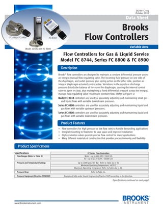
  • 1. 1 Data Sheet Brooks Flow Controllers Variable Area DescriptionDescriptionDescriptionDescriptionDescription PrPrPrPrProduct Featuroduct Featuroduct Featuroduct Featuroduct Featureseseseses Flow Controllers for Gas & Liquid Service Model FC 8744, Series FC 8800 & FC 8900 Model 1350G with FC 8800 DS-VA-FC-eng October, 2015 Brooks® flow controllers are designed to maintain a constant differential pressure across an integral manual flow regulating valve. The incoming fluid pressure on one side of the diaphragm, and outlet pressure plus spring action on the other side, position an integral diaphragm-actuated control valve. Variations in the supply or discharge pressure disturb the balance of forces on the diaphragm, causing the internal control valve to open or close, thus maintaining a fixed differential pressure across the integral, manual flow regulating valve resulting in constant flow. (Refer to Figure 1) Model FC 8744Model FC 8744Model FC 8744Model FC 8744Model FC 8744 controllers are used for accurately adjusting and maintaining small gas and liquid flows with variable downstream pressures. Series FC 8800Series FC 8800Series FC 8800Series FC 8800Series FC 8800 controllers are used for accurately adjusting and maintaining liquid and gas flows with variable upstream pressures. Series FC 8900Series FC 8900Series FC 8900Series FC 8900Series FC 8900 controllers are used for accurately adjusting and maintaining liquid and gas flows with variable downstream pressures. • Flow controllers for high pressure or low flow rates to handle demanding applications • Integral mounting to flowmeter to save space and improve installation • High-resolution valves provide precise flow control for many applications • Many different materials of construction that provides process immunity and flexibility FC 8800/ FC 8900 FC 8744 PrPrPrPrProduct Specificationsoduct Specificationsoduct Specificationsoduct Specificationsoduct Specifications SpecificationsSpecificationsSpecificationsSpecificationsSpecifications FC Series Flow ControllersFC Series Flow ControllersFC Series Flow ControllersFC Series Flow ControllersFC Series Flow Controllers Flow Ranges (Refer to Table 1)Flow Ranges (Refer to Table 1)Flow Ranges (Refer to Table 1)Flow Ranges (Refer to Table 1)Flow Ranges (Refer to Table 1) Water - up to 480 GPH / 1820 l/h Air - up to 2130 SCFH / 56000 ln /h Pressure and Temperature RatingsPressure and Temperature RatingsPressure and Temperature RatingsPressure and Temperature RatingsPressure and Temperature Ratings Up to 1000 psig / 69 Bar. Refer to Table 2a or 2b Minimum Operating Temperature: -40°F/C Maximum Operating Temprature: Refer to Tables 2a or 2b. Pressure DropPressure DropPressure DropPressure DropPressure Drop Refer to Table 2a. Pressure Equipment DirectivePressure Equipment DirectivePressure Equipment DirectivePressure Equipment DirectivePressure Equipment Directive (97/23/EC)(97/23/EC)(97/23/EC)(97/23/EC)(97/23/EC) Equipment falls under Sound Engineering Practice (SEP) according to the directive. (Specifications continued on next page)
  • 2. 2 PrPrPrPrProduct Specifications (conoduct Specifications (conoduct Specifications (conoduct Specifications (conoduct Specifications (continued)tinued)tinued)tinued)tinued) SpecificationsSpecificationsSpecificationsSpecificationsSpecifications FC Series Flow ControllersFC Series Flow ControllersFC Series Flow ControllersFC Series Flow ControllersFC Series Flow Controllers Materials of ConstructionMaterials of ConstructionMaterials of ConstructionMaterials of ConstructionMaterials of Construction Controller BodyController BodyController BodyController BodyController Body 316 Stainless Steel, Brass or Aluminum (FC 8744 only). Refer to Table 3 Controller DiaphragmController DiaphragmController DiaphragmController DiaphragmController Diaphragm Buna-N, Teflon® or Viton® fluoroelastomers. Refer to Table 3. Needle ValveNeedle ValveNeedle ValveNeedle ValveNeedle Valve 316 Stainless Steel Cartridge Valve. Refer to Figure 3. Refer to data sheet DS-VA-CART-eng. 316 Stainless Steel NRSTM Valve. Refer to Figure 2. Refer to data sheet DS-VA-8503-eng. 316 Stainless Steel high flow needle valve type. Refer to Table 3. O-ringsO-ringsO-ringsO-ringsO-rings Viton® fluoroelastomers, Buna-N, Kalrez® (SS body only), EPR (SS body only), Kalrez/Teflon (SS body only). Refer to Table 3. DimensionsDimensionsDimensionsDimensionsDimensions Refer to Figure 4 SizingSizingSizingSizingSizing Refer to Table 4. Material CertificationMaterial CertificationMaterial CertificationMaterial CertificationMaterial Certification Certification to NACE MR-01-75; (Stainless Steel body only)(Stainless Steel body only)(Stainless Steel body only)(Stainless Steel body only)(Stainless Steel body only) Certification to EN 10204-2.2; Certification to EN 10204-3.1 Ordering Information / Model CodesOrdering Information / Model CodesOrdering Information / Model CodesOrdering Information / Model CodesOrdering Information / Model Codes Refer to Model Code Figure 3 Cutaway View, Cartridge Valve Figure 1 Cutaway View, Principle of Operation Figure 2 Cutaway View, NRS Valve
  • 3. 3 PrPrPrPrProduct Specifications - Flow Ranges, Product Specifications - Flow Ranges, Product Specifications - Flow Ranges, Product Specifications - Flow Ranges, Product Specifications - Flow Ranges, Pressuressuressuressuressure /e /e /e /e / TTTTTemperemperemperemperemperaturaturaturaturature Ratings & Pre Ratings & Pre Ratings & Pre Ratings & Pre Ratings & Pressuressuressuressuressure Dre Dre Dre Dre Dropopopopop Table 1 FC Series Flow Ranges Table 2a FC Series Pressure / Temperature Ratings and Pressure Drop Table 2b FC Series Pressure / Temperature Ratings CRN
  • 4. 4 PrPrPrPrProduct Specifications (conoduct Specifications (conoduct Specifications (conoduct Specifications (conoduct Specifications (continued)tinued)tinued)tinued)tinued) Table 3 FC Series Materials of Construction / Connection / Valve Option Table 4 Sizing Chart
  • 5. 5 PrPrPrPrProduct Dimensionsoduct Dimensionsoduct Dimensionsoduct Dimensionsoduct Dimensions Figure 4 Flow Controller Dimensional Drawings Model FC 8744 Model FC 8830 Series FC 8800/8900
  • 6. 6 Model CodeModel CodeModel CodeModel CodeModel Code Code DescriptionCode DescriptionCode DescriptionCode DescriptionCode Description Code OptionCode OptionCode OptionCode OptionCode Option Option DescriptionOption DescriptionOption DescriptionOption DescriptionOption Description I.I.I.I.I. Base Model Number FCA87FCA87FCA87FCA87FCA87 Low flow gases and liquids with variable downstream pressure FCA88FCA88FCA88FCA88FCA88 Gases and liquids with variable upstream pressure FCA89FCA89FCA89FCA89FCA89 Gases and liquids with variable downstream pressure II.II.II.II.II. Type of Use 0000000000 General use, standard operating pressure, integral connection to Models 1350 & 1355 0202020202 General use, standard operating pressure, integral NPT connections 0505050505 General use, high operating pressure, integral NPT connections 1212121212 High flow rates, standard operating pressure, integral NPT connections 1515151515 High flow rates, high operating pressure, integral NPT connections 30*30*30*30*30* Very high flow rates, standard operating pressure, integral NPT connections 4040404040 Precise control, standard operating pressure, integral connection to Models 1350 & 1355 4242424242 Precise control, standard operating pressure, integral NPT connections 4545454545 Precise control, high operating pressure, integral NPT connections 44*44*44*44*44* Very precise control, low operating pressure, adapters required III.III.III.III.III. Body Material A*A*A*A*A* Brass BBBBB 316 Stainless Steel C*C*C*C*C* Aluminum - FC 8744 only DDDDD 316 Stainless Steel - CRN IV.IV.IV.IV.IV. Diaphragm Material 11111 Viton 22222 Teflon 3*3*3*3*3* Buna V.V.V.V.V. O-ringMaterial AAAAA Viton BBBBB Buna CCCCC Kalrez - Stainless Steel body only DDDDD Kalrez/Teflon - Stainless Steel body only EEEEE EPR - Stainless Steel body only YYYYY Not applicable VI.VI.VI.VI.VI. Process Connection Size & Type 11111 1/4” FNPT 22222 1/8 FNPT 33333 1/8” Tube Compression 44444 1/4” Tube Compression 5*5*5*5*5* 1/4” I. D. Hose 6*6*6*6*6* 3/4” FNPT 77777 Integral 5/16-24 UNF Thd VII.VII.VII.VII.VII. Valve Configuration AAAAA Cartridge Valve, Low Flow BBBBB Cartridge Valve, Medium Flow CCCCC Cartridge Valve, High Flow DDDDD NRS Needle Valve, Size #1 (316 SS only) EEEEE NRS Needle Valve, Size #2 (316 SS only) FFFFF NRS Needle Valve, Size #3 (316 SS only) GGGGG NRS Needle Valve, Size #4 (316 SS only) HHHHH NRS Needle Valve, Size #5 (316 SS only) JJJJJ NRS Needle Valve, Size #6 (316 SS only) LLLLL High Flow Needle Valve YYYYY No Valve VIII.VIII.VIII.VIII.VIII. Valve Option 00000 Knob only IX.IX.IX.IX.IX. Filter AAAAA None BBBBB Filter on Inlet CCCCC Filters on Inlet & Outlet X.X.X.X.X. Mounting Configuration 00000 None 11111 Mounting Bracket, Plated Steel (standard) Note: N/A FC 8744 22222 Mounting Bracket, Stainless Steel Note: N/A FC 8744 * CRN NOT AVAILABLE Sample Standard Model Code (Fields incomplete )Sample Standard Model Code (Fields incomplete )Sample Standard Model Code (Fields incomplete )Sample Standard Model Code (Fields incomplete )Sample Standard Model Code (Fields incomplete ) IIIII IIIIIIIIII IIIIIIIIIIIIIII IVIVIVIVIV VVVVV VIVIVIVIVI VIIVIIVIIVIIVII VIIIVIIIVIIIVIIIVIII IXIXIXIXIX XXXXX XIXIXIXIXI XIIXIIXIIXIIXII FCA88FCA88FCA88FCA88FCA88 0000000000 BBBBB 11111 AAAAA 11111 DDDDD 00000 AAAAA 00000 (Model Code continued on next page)
  • 7. 7 Model Code (ConModel Code (ConModel Code (ConModel Code (ConModel Code (Continued)tinued)tinued)tinued)tinued) Sample Standard Model Code (Fields complete)Sample Standard Model Code (Fields complete)Sample Standard Model Code (Fields complete)Sample Standard Model Code (Fields complete)Sample Standard Model Code (Fields complete) IIIII IIIIIIIIII IIIIIIIIIIIIIII IVIVIVIVIV VVVVV VIVIVIVIVI VIIVIIVIIVIIVII VIIIVIIIVIIIVIIIVIII IXIXIXIXIX XXXXX XIXIXIXIXI XIIXIIXIIXIIXII FCA88FCA88FCA88FCA88FCA88 0000000000 BBBBB 11111 AAAAA 11111 DDDDD 00000 AAAAA 00000 AAAAA 11111 Code DescriptionCode DescriptionCode DescriptionCode DescriptionCode Description Code OptionCode OptionCode OptionCode OptionCode Option Option DescriptionOption DescriptionOption DescriptionOption DescriptionOption Description XI.XI.XI.XI.XI. Material Certifications AAAAA None BBBBB Certification to NACE MR-010-75 CCCCC Material Certification EN 10204-2.2 DDDDD Material Certification EN 10204-3.1 EEEEE Certification to NACE & Material Certification EN 10204-2.2 FFFFF Certification to NACE & Material Certification EN 10204-3.1 XII.XII.XII.XII.XII. Additional Cleaning 11111 Standard Cleaning Process 22222 Degrease and Clean for Oxygen Service * CRN NOT AVAILABLE
  • 8. 8 BrBrBrBrBrooks Service and Supportooks Service and Supportooks Service and Supportooks Service and Supportooks Service and Support Brooks is committed to assuring all of our customers receive the ideal flow solution for their application, along with outstanding service and support to back it up. We operate first class repair facilities located around the world to provide rapid response and support. Each location utilizes primary standard calibration equipment to ensure accuracy and reliability for repairs and recalibration and is certified by our local Weights and Measures Authorities and traceable to the relevant International Standards. Visit www.BrooksInstrument.com to locate the service location nearest to you. STSTSTSTSTARARARARARTTTTT-UP SERVICE-UP SERVICE-UP SERVICE-UP SERVICE-UP SERVICE AND IN-SITU CALIBRAAND IN-SITU CALIBRAAND IN-SITU CALIBRAAND IN-SITU CALIBRAAND IN-SITU CALIBRATIONTIONTIONTIONTION Brooks Instrument can provide start-up service prior to operation when required. For some process applications, where ISO-9001 Quality Certification is important, it is mandatory to verify and/or (re)calibrate the products periodically. In many cases this service can be provided under in-situ conditions, and the results will be traceable to the relevant international quality standards. CUSTCUSTCUSTCUSTCUSTOMER SEMINARSOMER SEMINARSOMER SEMINARSOMER SEMINARSOMER SEMINARS ANDANDANDANDAND TRAININGTRAININGTRAININGTRAININGTRAINING Brooks Instrument can provide customer seminars and dedicated training to engineers, end users, and maintenance persons. Please contact your nearest sales representative for more details. HELP DESKHELP DESKHELP DESKHELP DESKHELP DESK In case you need technical assistance: Americas 1 888 554 FLOW Europe +31 (0) 318 549 290 Asia +81 3 (0) 5633 7100 Due to Brooks Instrument's commitment to continuous improvement of our products, all specifications are subject to change without notice. TRADEMARKS Brooks ............................................................. Brooks Instrument, LLC All other trademarks are the property of their respective owners.
  • 9. 1 The Brooks® SolidSense II® Pressure Transducers are designed for stable, accurate, and reliable pressure monitoring in high purity and ultra-high purity (UHP) applications. A combination of optimum design and materials improves both signal stability and reliability in numerous pressure measurement applications. Pressure transducers are widely used in high purity and ultra-high purity fluid storage and delivery systems in many industries. Unfortunately, a number of current transducers rely on technologies that have problems with zero and span drift, thermal shift, and case stress. Adjusting the transducer to rectify errors requires ongoing maintenance that increases downtime and cost of ownership. The third generation SolidSense II pressure transducers by Brooks Instrument utilize glass-fused strain gauge technology enabling a new level of performance for micro electronics and industrial applications. SolidSense II pressure transducers employ ultra stable, micro machined silicon strain gauges that are matched and fused to the metal diaphragm at high temperature to relieve manufacturing induced stress. The process reduces drift or lack of zero stability commonly associated with competitive products. Consequently, down time for zero adjustment to compensate for drift is significantly reduced. In addition, the unique mechanical design eliminates torque effects during installation. SolidSense II digital architecture enables automated software driven calibration and a wide range of thermal compensation routines, unlike the passive compensation used in competitive devices. This enhances measurement repeatability regardless of changes to the operational environment. SolidSense II devices feature 316L stainless steel wetted surfaces electropolished to 5- and 10-micro in. (5- and 10-Ra) to maintain the purity of the measured fluid. Data Sheet Pressure Transducers OverviewOverviewOverviewOverviewOverview Superior stability and reliability for demanding pressure measurement applications SolidSense II® Pressure Transducers SolidSense II® Pressure Transducers DS-PR-SolidSenseII-PT-eng April, 2016
  • 10. 2 PrPrPrPrProduct Descriptionoduct Descriptionoduct Descriptionoduct Descriptionoduct Description Industry StandarIndustry StandarIndustry StandarIndustry StandarIndustry Standard Ind Ind Ind Ind Interfaceterfaceterfaceterfaceterface Options and outputs DigitalDigitalDigitalDigitalDigital ThermalThermalThermalThermalThermal CompensationCompensationCompensationCompensationCompensation Multi-point temperature compensation Digital LinearizationDigital LinearizationDigital LinearizationDigital LinearizationDigital Linearization Consistency of performance StrStrStrStrStress Isolation Stageess Isolation Stageess Isolation Stageess Isolation Stageess Isolation Stage To reduce stress introduced during mounting SensorSensorSensorSensorSensor AAAAAttacttacttacttacttachmenhmenhmenhmenhmenttttt Glass fusion bonding to relieve stress Sensor ConstructionSensor ConstructionSensor ConstructionSensor ConstructionSensor Construction Paired strain gauges to reduce stress induced drift WWWWWetted Materialsetted Materialsetted Materialsetted Materialsetted Materials 316L meets SEMI F20Fully Swept FlowpathFully Swept FlowpathFully Swept FlowpathFully Swept FlowpathFully Swept Flowpath Complete removal of residual gas FeaturFeaturFeaturFeaturFeatureseseseses BenefitsBenefitsBenefitsBenefitsBenefits Two pairs of strain gauge sensors Precision matched sensors for improved performance Glass fusion process to High temperature glass bonding drives off any mechanically induced build up of stress bond strain gauge from sensor manufacturing process Stress isolation stage Minimizes stress introduced during installation of the transducer Digital temperature compensation Improved thermal stability over entire range of temperature Digital linearization and calibration Consistency of performance, improved reproducibility Fully swept flowpath Ensures contamination-free pressure measurement Integrated fully rotatable display option Local indication of process pressure for safe system maintenance Compact with no special wiring for easy system integration/installation
  • 11. 3 Sensor ConstructionSensor ConstructionSensor ConstructionSensor ConstructionSensor Construction SolidSense II utilizes proprietary micro machined silicon strain gauges that are ultra stable and suitable for high purity and ultra-high purity requirements. A design feature for controlling stress is the use of dual paired gauges. By using two paired gauges in Wheatstone bridge circuitry, pressure signal is maximized enhancing stability. Sensor AttachmentSensor AttachmentSensor AttachmentSensor AttachmentSensor Attachment A key step for eliminating machining stress in the diaphragm is the glass fusion process used to bond the strain gauges to the sensor diaphragm. This process occurs at 600O C and drives off any mechanically induced build up of stress resulting in a highly stable and accurate sensor. By using silicon strain gauge technology and the glass fusion bonding method for SolidSense II, there is no stress induced from thermal gradients between structural materials. In some competitive designs, different thermal expansion coefficients between the metal casing and ceramic electrode (upon which the sensor is mounted) allow for flexing of the sensor which is interpreted as a false pressure change. Stress Isolation StageStress Isolation StageStress Isolation StageStress Isolation StageStress Isolation Stage SolidSense II incorporates an isolation stage shown at right that minimizes stress from: (1) thermal heating during any adjacent welding and (2) torque during installation in gas panels, gas interface boxes, valve manifold boxes, etc. By preventing stress during these two scenarios, creep (drift) is eliminated during subsequent usage. Wetted MaterialsWetted MaterialsWetted MaterialsWetted MaterialsWetted Materials Made from 316L that meets SEMI F20. Surface finish complies with SEMI F19. Product is assembled in clean environment compliant with ASTM F1374-92 - meets requirement for ultra- high purity application. PrPrPrPrProduct Descriptionoduct Descriptionoduct Descriptionoduct Descriptionoduct Description Ground VIn 5V R1, Tension R2, Comp. R3, Comp. R4, Tension Pressure Tension CompressionCompression Stress Isolation Groove Diaphragm Strain Gauges (bonded on diaphragm) Reference Volume Fully rotatable displayFully rotatable displayFully rotatable displayFully rotatable displayFully rotatable display This integrated display option reduces gas panel overall size constraints by eliminating the requirement for a standalone pressure gauge and reduces height by 2-6 inches. The display is fully rotatable - covering 4 quadrants - and no tools are required to set/secure the position. A bright LED display ensures readability in typical compact installation conditions. It provides exact visual feedback and verification of line pressure and an over pressure indication (roughly at 110% FS). The fully integrated display combined with the SSII high performance provides exact pressure measurement choice for field upgrades and new gas processing system designs.
  • 12. 4 Digital Linearization and CalibrationDigital Linearization and CalibrationDigital Linearization and CalibrationDigital Linearization and CalibrationDigital Linearization and Calibration SolidSense II is calibrated with automated software which uses about 200 linearization points compared with 2 for some competing units. This results in consistency of performance from one transducer to the next (reproducibility). Due to automation, operator induced differences are eliminated. Digital Thermal CompensationDigital Thermal CompensationDigital Thermal CompensationDigital Thermal CompensationDigital Thermal Compensation SolidSense II uses multi-point digital temperature compensation. Some competitive devices rely on single or two point compensation to optimize device performance over the operating temperature range. For example, device performance might be checked at -10o C and 60o C to determine the dZ/dT and dS/dT (rate of zero/span change per temperature change) with the temperature compensation interpolated for other values. SolidSense II can incorporate five separate data points, which are typically taken at -10o C, -5o C, 20o C, 40o C and 60o C, giving the temperature compensation algorithm far better resolution. Fully swept flowpathFully swept flowpathFully swept flowpathFully swept flowpathFully swept flowpath The SolidSense II incorporates an all-swept flowpath and very small internal volume allowing complete removal of residual fluid during the purge cycle. As a result inert, dry and clean surfaces are available at the end of the purge cycle. ASTM F1397 establishes a dry-down requirement to 20 ppbv H20 within 30 minutes. As accompanying data shows, the dead end configuration of the SolidSense II recovered to desired level within 11.5 minutes and the flow thru configuration recovered in 9.5 minutes, both well below the requirement indicated in standard. PrPrPrPrProduct Descriptionoduct Descriptionoduct Descriptionoduct Descriptionoduct Description Pulse Test Dry Down SolidSense-II Transducer GFD01A3DCS Model -50 0 50 100 150 200 250 300 350 400 450 0 5 10 15 20 25 Time (min) Water(ppb) Water Contribution Surface Mount Spool Piece Water Contribution Surface Mount Transducer Subtracted Pulse Test Dry Down SolidSense-II Transducer GFF01A30FS Model -100 -50 0 50 100 150 200 250 300 350 400 0 5 10 15 20 25 Time (min) Water(ppb) Water Contribution VCR Spool Piece Water Contribution VCR Mount Transducer Subtracted Thermal Zero 0.07 (0.23)(0.22) (0.04) (0.18) (0.45) (1.00) 2.68 2.86 0.57 0.52 (1.00) (0.50) ‐ 0.50 1.00 1.50 2.00 2.50 3.00 ‐30 ‐20 ‐10 0 10 20 30 40 50 60 70 Temperature (deg C) ZeroDeviation(%FS/100degF) Brooks 1 Brooks 2 Comp A 1 Comp A 2 Comp B 1 Comp B 2 Thermal Span (0.14) 0.020.10 0.29 (0.66) (0.44) 1.83 (2.07) 1.43 0.76 0.91 (2.01) (2.50) (2.00) (1.50) (1.00) (0.50) ‐ 0.50 1.00 1.50 2.00 ‐25 ‐5 15 35 55 75 Temperature (deg C) ZeroDeviation(%FS/100degF) Brooks 1 Brooks 2 Comp A1 Comp A2 Comp B1 Comp B2
  • 13. 5 RobustnessRobustnessRobustnessRobustnessRobustness The SolidSense II design incorporates a stress isolation stage. This prevents stresses built up during installation of transducers from being transmitted to diaphragm. As a result, SolidSense II will not require frequent resetting of zero after installation and in operation. A number of applications involve subjecting the pressure transducer to rapid pressure cycling in a purge cycle. As shown in test results, SolidSense II will not temporarily indicate inaccurate pressure readings due to the Joule-Thompson effect. In some competitive devices this may cause false alarms and shut down the gas distribution system. PrPrPrPrProduct Descriptionoduct Descriptionoduct Descriptionoduct Descriptionoduct Description Zero StabilityZero StabilityZero StabilityZero StabilityZero Stability Minimal drift, creep and shifts during installation and service life. Stabilty - 2,000,000 pressure cycles without failure MetrologyMetrologyMetrologyMetrologyMetrology Calibration system that is traceable to international primary standards with minimal uncertainty - precise dependable pressure measurements. Accurate pressure readings during purge cycle Solid Sense II Pressure Cycle (0 psig - 2000 psig) 3000 psig device (0-5Vdc output) 0.0 0.5 1.0 1.5 2.0 2.5 3.0 3.5 4.0 4.5 52:39 53:46 54:59 56:12 57:25 58:38 59:51 Time (minutes) TransducerOutput(VDC)
  • 14. 6 PrPrPrPrProductoductoductoductoduct ApplicationsApplicationsApplicationsApplicationsApplications Semiconductor ManufacturingSemiconductor ManufacturingSemiconductor ManufacturingSemiconductor ManufacturingSemiconductor Manufacturing Ultra-high purity gases and liquids are at the heart of semiconductor manufacturing operations. Their safe storage and distribution is vital to uninterrupted production. Gas cabinets, gas panels, valve manifold boxes and distribution valve boxes all require reliable pressure measurement of these fluids. Several design features and manufacturing processes described in more detail elsewhere in this data sheet enable superior accuracy and long-term stability. Two are emphasized here: The sensor isolation stage minimizes stress coupled from adjacent welding operations and torque from installation. By isolating stress during these two scenarios, stress-related creep or drift is eliminated. All gas cabinets are designed to handle purge cycles to facilitate safe changeover of cylinders. Whether these are automatic or manual, it is common to introduce a big surge in pressure followed by vacuum over very short period of time. Test results show that SolidSense II will not temporarily indicate inaccurate readings during purge cycles due to Joule-Thompson effect.
  • 15. 7 PrPrPrPrProductoductoductoductoduct ApplicationsApplicationsApplicationsApplicationsApplications Measure build-up across filtersMeasure build-up across filtersMeasure build-up across filtersMeasure build-up across filtersMeasure build-up across filters Many sanitary processes use filters to ensure product quality. As the load on the filter increases, a pressure differential between the inlet and outlet sides of the filter can be measured using SolidSense II. Once an established differential limit is reached, the filter can be preventively replaced before throughput goes down.
  • 16. 8 PrPrPrPrProduct Specificationsoduct Specificationsoduct Specificationsoduct Specificationsoduct Specifications PerformancePerformancePerformancePerformancePerformance Non-Display VersionNon-Display VersionNon-Display VersionNon-Display VersionNon-Display Version Display VersionDisplay VersionDisplay VersionDisplay VersionDisplay Version Temperature: Operating: -20O F to 180O F (-29O C to 82O C) -20°F to 140°F (-29°C to 60°C) Storage: -40O F to 180O F (-40O C to 82O C) -40°F to 167°F (-40°C to 75°C) Compensated: -4O F to 140O F (-20O C to 60O C) / 68O F to 140O F (20O C to 60O C) 0-10 Vdc version Burst Pressure: 400% full scale Proof Pressure: 200% full scale up to 2,000 psi, 150% full scale for higher ranges Accuracy: 0.25% full scale (BFSL) Response Time: < 5 msec Zero and Span Temperature Coefficient (each): >100 PSI Ranges Full Scale: +0.02% full scale/O F (-4O F to 140O F, -20O C to 60O C) +0.50% full scale (68O F to 140O F, 20O C to 60O C) 0 to 10 Vdc version <100 PSI Ranges Full Scale: +0.04% full scale/O F (-4O F to 140O F, -20O C to 60O C) +1.00% full scale (68O F to 140O F, 20O C to 60O C) 0 to 10 Vdc version MechanicalMechanicalMechanicalMechanicalMechanical Housing: Stainless steel, polymer plastics Wetted Parts: VIM-VAR 316L stainless steel, SEMI F20 Surface Finish: Compliant with SEMI F19 Cleanliness: Compliant to ASTM F1374-92 (2005) Internal Volume: 1.79cc Process Connections: (See Product Configurations for available options) Approximate Shipping Weight: 0.70 lb. (0.32 kg) ElectricalElectricalElectricalElectricalElectrical Non-Display VersionNon-Display VersionNon-Display VersionNon-Display VersionNon-Display Version Display VersionDisplay VersionDisplay VersionDisplay VersionDisplay Version Supply Current: Max. 10 mA Max. 30 mA Power Requirements: 10 to 30 Vdc for 4 to 20 mA output 15 to 30 Vdc for 4 to 20 mA output and no signal output 11 to 30 Vdc for 0 to 5 Vdc output 11 to 30 Vdc for 0 to 5 Vdc output 13 to 32 Vdc for 0 to 10 Vdc output 13 to 30 Vdc for 0 to 10 Vdc output Electrical Connections: Code B Bendix® connector (See page 11 for Code P Pigtail 6 ft long full list) Code D 15-pin HD D-sub connector Code K 9-pin D-sub Code A 4 ft pigtail with AMP® connector (3 pin) Code G 4 ft pigtail with AMP® connector (4 pin) Code H 6 inch pigtail with Molex® connector Electrical Protection: Reverse polarity for power connections Optional DisplayOptional DisplayOptional DisplayOptional DisplayOptional Display Digits: N/A -xxx to 1xxx Type: N/A 7 Segment Red LED Polarity: N/A Automatic (-) Display Over Pressure Reading Trigger: N/A 110% full scale ± 5% full scale (Display reading: 1---) Display Accuracy: N/A ±-0.25% of Rdg ± 1 Count for psi (excluding transducer output) N/A ± - 0.25% of Rdg ± 5 Count for kPa Character Size: N/A 0.30” height kPa/psi Switch: N/A Yes Rotatable: N/A Continuous rotation covering 4 quadrants Zero Pot: N/A Yes Zero Pot Adj. Screwdriver: N/A 1-1.2 mm flat type Approvals and ComplianceApprovals and ComplianceApprovals and ComplianceApprovals and ComplianceApprovals and Compliance FM Approval: Non-Incendive for use in Class I, Div II Groups A, B, C and D Hazardous Applications Excludes 0 to 10 Vdc and 15-pin HD D-Sub connector configurations, GI/integrated display pending EMC: Compliant to EU Directive 2004/108/EC RoHS: Compliant to EU Directive 2002/95/EC
  • 17. 9 PrPrPrPrProduct Dimensions (Standaroduct Dimensions (Standaroduct Dimensions (Standaroduct Dimensions (Standaroduct Dimensions (Standard Cond Cond Cond Cond Configurfigurfigurfigurfigurations)ations)ations)ations)ations) Shown are just a few of the most common configurations of the SolidSense II® pressure transducers. The SolidSense II pressure transducers are available in over 40 configurations. For more information and a complete selection of configurations available see the Brooks Instrument Installation and Operation Manual “XXXXX-PR-PR-PR-PR-PR-SolidSense II-PT-SolidSense II-PT-SolidSense II-PT-SolidSense II-PT-SolidSense II-PT-eng-eng-eng-eng-eng” by visiting our website at www.BrooksInstrument.com or contact your nearest Brooks customer service representative for assistance. NO. 4 VCR SWIVEL FEMALE PIGTAIL GFDXXXXPSF FITTING A333124002 CABLE ME0521302-001 PIGTAIL .84 [21.33] 3.40 [86.36] PIGTAIL NO. 4 VCR SWIVEL MALE PIGTAIL GFDXXXXPSM FITTING A333124001 CABLE ME0521302-001 .84 [21.33] 4.00 [101.6] W-SEAL Pigtail GFDXXXXP5W FITTING A333366001 1.53 [38.97] 3.88 [98.55] .84 [21.33] CABLE ME0521302-001 PIGTAIL .84 [21.33] VCR FIXED MALE THRUTUBE PIGTAIL GFFXXXXPVM FITTING A333125004 2.24 [56.90] 3.36 [85.40] CABLE ME0521302-001 BENDIX TUBE STUB/TUBE STUB THRUTUBE BENDIX GFFXXXXB4T FITTING A333125001 .84 [21.33] 1.85 [46.98] 3.23 [82.04] .31 [7.92] 2X .42 [10.79] 2X .25 [6.35] TUBE STUB/TUBE STUB THRUTUBE PIGTAIL GFFXXXXP4T FITTING A333125001 PIGTAIL 1.85 [46.98] .84 [21.33] 3.36 [85.40] .31 [7.92] 2X .42 [10.79] 2X .25 [6.35] CABLE ME0521302-001 VCR SWIVEL FEMALE BENDIX GFDXXXXBSF FITTING A333124002 NO. 4 BENDIX .84 [21.33] 3.30 [83.86] 1 1/8" C-SEAL W/AMP ON PIGTAIL GFDXXXXMCS FITTING A333127001 CABLE ME0521302-001 .84 [21.33] 1.12 [28.57] 3.51 [89.15] PIGTAIL VCR SWIVEL MALE BENDIX GFDXXXXBSM FITTING A333124001 BENDIX NO. 4 .84 [21.33] 3.89 [98.84]
  • 18. 10 Optional CablesOptional CablesOptional CablesOptional CablesOptional Cables AAAAAvailable for the SolidSense II Prvailable for the SolidSense II Prvailable for the SolidSense II Prvailable for the SolidSense II Prvailable for the SolidSense II Pressuressuressuressuressureeeee TTTTTrrrrransducersansducersansducersansducersansducers CableCableCableCableCable CableCableCableCableCable Transducer ElectricalTransducer ElectricalTransducer ElectricalTransducer ElectricalTransducer Electrical TransducerTransducerTransducerTransducerTransducer Part NumberPart NumberPart NumberPart NumberPart Number DescriptionDescriptionDescriptionDescriptionDescription Cable lengthCable lengthCable lengthCable lengthCable length Connector RequiredConnector RequiredConnector RequiredConnector RequiredConnector Required OutputOutputOutputOutputOutput EL0001965104 Cable w/ four pin female Bendix connector to connect to transducer; flying leads on opposite end for power connection 10ft. 4 pin male Bendix 4-20 mA EL0001965105 Cable w/ four pin female Bendix connector to connect to transducer; flying leads on opposite end for power connection 25ft. 4 pin male Bendix 4-20 mA PrPrPrPrProduct Dimensions (Optional Display LR056)oduct Dimensions (Optional Display LR056)oduct Dimensions (Optional Display LR056)oduct Dimensions (Optional Display LR056)oduct Dimensions (Optional Display LR056) The SolidSense II pressure transducer is available with an optional display: Model LR056, for details on this display see DS-PR-LR056-eng Visit the Brooks Instrument website for product documentation at: www.BrooksInstrument.com/Manuals. LR056 Pressure Transducer Display Dimensions Local display option for SolidSense II with Bendix connector and 4-20 mA output 9999 PrPrPrPrProduct Dimensions (GID/GIF Options)oduct Dimensions (GID/GIF Options)oduct Dimensions (GID/GIF Options)oduct Dimensions (GID/GIF Options)oduct Dimensions (GID/GIF Options)
  • 19. 11 Model CodeModel CodeModel CodeModel CodeModel Code SampleSampleSampleSampleSample Model CodeModel CodeModel CodeModel CodeModel Code Code DescriptionCode DescriptionCode DescriptionCode DescriptionCode Description Code OptionCode OptionCode OptionCode OptionCode Option Option DescriptionOption DescriptionOption DescriptionOption DescriptionOption Description I.I.I.I.I. Base Model Code GFGFGFGFGF Pressure Transducer GIGIGIGIGI Pressure Transducer with integrated display II.II.II.II.II. Body Type DDDDD Dead End FFFFF Flow Through III.III.III.III.III. PSI 0000000000 30 0101010101 100 0202020202 250 X2X2X2X2X2 235 0505050505 500 1010101010 1000 2525252525 2500 3030303030 3000 4545454545 45 6060606060 60 1515151515 1500 Torr IV.IV.IV.IV.IV. Pressure Reference AAAAA Absolute, psi CCCCC Compound, psi GGGGG Gauge, psi EEEEE Absolute, mPa/kPa RRRRR Compound, mPa/kPa DDDDD Gauge, mPa/kPa BBBBB Absolute, Bar PPPPP Compound, Bar SSSSS Gauge, Bar TTTTT Absolute Torr V.V.V.V.V. Output 33333 0.00 to 10.00 Vdc 44444 4 to 20 mA 55555 0.05 to 5.05 Vdc 66666 0.2 to 5.2 Vdc 77777 2 to 10 Vdc 88888 No signal output (GI model with display only) VI.VI.VI.VI.VI. Electrical Connection BBBBB Bendix® Connector PPPPP 6 ft (2m) Pigtail DDDDD 15 Pin HD D-Sub Connector EEEEE 9 inch Pigtail with 15 Pin (Standard) D-Sub Connector M+M+M+M+M+ 5 inch (0.127m) Pigtail with AMP® Connector (4-pin) JJJJJ Bendix® with Jumper B-D (Offered with 4-20 mA only) LLLLL 10 ft (3m) Pigtail RRRRR 8 inch Pigtail with AMP® Connector (4-pin) NNNNN 16.5 ft cable with Bendix® Type (Bayonet) V+V+V+V+V+ 18 inch Pigtail with 6-pin Molex® Connector CCCCC 6 ft (2m) Pigtail with 9-pin D Connector G+G+G+G+G+ 4 ft Pigtail with AMP® Connector (4-pin) H+H+H+H+H+ 6 inch Pigtail with Molex® Connector KKKKK 9-pin D-Sub A+A+A+A+A+ 4 ft Pigtail with AMP® Connector (3-pin) F+F+F+F+F+ 8 inch Pigtail with AMP® Connector (3-pin) Q+Q+Q+Q+Q+ M12 4-pin Male Connector SSSSS 2m (79”) Pigtail with 9-Pin D Connector Z+Z+Z+Z+Z+ 36 inch Pigtail ith Bendix® Connector (Bayonet) VII.VII.VII.VII.VII. Fittings 4S4S4S4S4S Tube Weld Stub 1/4” O.D. (GFD Only)* CS+CS+CS+CS+CS+ Surface Mount, 1.125” C-Seal, Standard (GFD & GID Only) CHCHCHCHCH Surface Mount, 1.5” C-Seal, High Flow K1H (GFD Only) SCSCSCSCSC Surface Mount, 1.5” C-Seal (GFD Only) 5W5W5W5W5W Surface Mount, 1.5” W-Seal (GFD Only) 4W4W4W4W4W Surface Mount, 1.125” W-Seal (GFD Only) CD+CD+CD+CD+CD+ Surface Mount, 1.125” C-Seal, 0.5” longer gland (GFD & GID Only) NTNTNTNTNT 1/4” NPT (GFD only) VM+VM+VM+VM+VM+ Face Seal, fixed male (x2 on Duncan T for GFF) (GFF & GIF Only) VSVSVSVSVS Face Seal, fixed male/swivel female on Duncan T (GFF Only) SM+SM+SM+SM+SM+ Face Seal, swivel male (x2 on Duncan T for GFF) SFSFSFSFSF Face Seal, swivel female (x2 on Duncan T for GFF) 4T4T4T4T4T Duncan T, 1/4” Tube Weld Stub (GFF Only)* 3T3T3T3T3T Duncan T, 3/8” Tube Weld Stub (GFF Only)* 3M3M3M3M3M Duncan T, 3/8” with Face Seal, swivel male (GFF Only) 2T2T2T2T2T Duncan T, 1/2” Tube Weld Stub (GFF Only)* CTCTCTCTCT Tube Stub, 3/8” OD (Suitable for compression joint) (x2 on Union T for GFF)(GFD & GFF) VIII.VIII.VIII.VIII.VIII. Special Option RRRRR Integrated Display Removed (For base model GI only) * Tube stubs (4S, 4T, 3T and 2T) are not suitable for compression joint. Use CT for compression joint. GID/GIF Integrated Display options are only available with the fittings and connectors noted with “+”. IIIII IIIIIIIIII IIIIIIIIIIIIIII IVIVIVIVIV VVVVV VIVIVIVIVI VIIVIIVIIVIIVII VIIIVIIIVIIIVIIIVIII GFGFGFGFGF FFFFF 0202020202 CCCCC 44444 PPPPP SFSFSFSFSF
  • 20. 12 BrBrBrBrBrooks Service and Supportooks Service and Supportooks Service and Supportooks Service and Supportooks Service and Support TRADEMARKS AMP ......................................................................................... Tyco Electronics Bendix ..................................................................................... Amphenol Corp. Brooks ........................................................................... Brooks Instrument, LLC Molex ............................................................................................... Molex Inc. SolidSense II .................................................................. Brooks Instrument, LLC Brooks is committed to assuring all of our customers receive the ideal flow solution for their application, along with outstanding service and support to back it up. We operate first class repair facilities located around the world to provide rapid response and support. Each location utilizes primary standard calibration equipment to ensure accuracy and reliability for repairs and recalibration and is certified by our local Weights and Measures Authorities and traceable to the relevant International Standards. Visit www.BrooksInstrument.com to locate the service location nearest to you. STSTSTSTSTARARARARARTTTTT-UP SERVICE-UP SERVICE-UP SERVICE-UP SERVICE-UP SERVICE AND IN-SITU CALIBRAAND IN-SITU CALIBRAAND IN-SITU CALIBRAAND IN-SITU CALIBRAAND IN-SITU CALIBRATIONTIONTIONTIONTION Brooks Instrument can provide start-up service prior to operation when required. For some process applications, where ISO-9001 Quality Certification is important, it is mandatory to verify and/or (re)calibrate the products periodically. In many cases this service can be provided under in-situ conditions, and the results will be traceable to the relevant international quality standards. CUSTCUSTCUSTCUSTCUSTOMER SEMINARSOMER SEMINARSOMER SEMINARSOMER SEMINARSOMER SEMINARS ANDANDANDANDAND TRAININGTRAININGTRAININGTRAININGTRAINING Brooks Instrument can provide customer seminars and dedicated training to engineers, end users, and maintenance persons. Please contact your nearest sales representative for more details. HELP DESKHELP DESKHELP DESKHELP DESKHELP DESK In case you need technical assistance: Americas 1 888 554 FLOW Europe +31 (0) 318 549 290 Asia +81 (0) 3 5633 7100 Due to Brooks Instrument's commitment to continuous improvement of our products, all specifications are subject to change without notice.
  • 21. 1 The Brooks® Sho-RateTM Series glass tube variable area flow meter has been the industry standard glass tube variable area meter for decades. This glass tube meter is ideal for a variety of gas and liquid applications. These meters are particularly suited for purge applications. The base configuration uses a borosilicate glass tube installed in an aluminum frame with 316SS end blocks, adaptors, and valve. Additional material options, valve options, and flow controllers are available to provide the appropriate configuration for a wide variety of applications. • Standard direct read scales on tube for all fluids and fluid conditions (user selected) • Standard millimeter scales with flow curves for all fluids and fluid conditions (user selected) • Scale length (approximate) 65mm, 150mm • Magnifier built into front shield • Flowmeter options: Multiple fitting adapters for all world areas No valve, cartridge valve and precision control valve Inlet & outlet valves Integral flow controller, upstream & downstream Multiple connection fittings to fit all applications Multiple approval certifications for world wide usage Data Sheet Sho-RateTM Models 1350G & 1355G Variable Area OverviewOverviewOverviewOverviewOverview PrPrPrPrProduct Featuroduct Featuroduct Featuroduct Featuroduct Featureseseseses DS-VA-1350G-eng April, 2016 Sho-RateTM 1350G & 1355G Series Low Flow Glass Tube Flowmeters
  • 22. 2 FeaturFeaturFeaturFeaturFeatures and Benefitses and Benefitses and Benefitses and Benefitses and Benefits OptionalOptionalOptionalOptionalOptional VVVVValves for Inlet or Outletalves for Inlet or Outletalves for Inlet or Outletalves for Inlet or Outletalves for Inlet or Outlet • Cartridge III Valves • NRSTM (Non-Rising Stem) • Integral Flow Controllers ThrThrThrThrThreadedeadedeadedeadedeaded JacJacJacJacJack Scrk Scrk Scrk Scrk Screwewewewew • Tubes sealed on compression gasket MeteringMeteringMeteringMeteringMetering TTTTTubesubesubesubesubes • Heavy-wall, precision bore • Borosilicate glass • Removeable without disconnnecting instrument InInInInInterterterterterccccchangeablehangeablehangeablehangeablehangeable TTTTTubes and Floatsubes and Floatsubes and Floatsubes and Floatsubes and Floats with Dirwith Dirwith Dirwith Dirwith Direct Reading (DR) Scales onect Reading (DR) Scales onect Reading (DR) Scales onect Reading (DR) Scales onect Reading (DR) Scales on thethethethethe TTTTTubeubeubeubeube • Allows users to change ranges as the application dictates • DR Scale on Tube is determined by the user; based on specific application needs • Eliminates reading errors introduced by detached scales; resulting in a more accurate indication of flow Rugged, Single Piece FrRugged, Single Piece FrRugged, Single Piece FrRugged, Single Piece FrRugged, Single Piece Frame Constructioname Constructioname Constructioname Constructioname Construction InInInInIntegrtegrtegrtegrtegral Float Stopsal Float Stopsal Float Stopsal Float Stopsal Float Stops • Prevent loss of float during tube removal Clear PClear PClear PClear PClear Polycarbonateolycarbonateolycarbonateolycarbonateolycarbonate FFFFFaceshieldaceshieldaceshieldaceshieldaceshield • Built-in magnifier for easier float and scale reading SelfSelfSelfSelfSelf Aligning BlocAligning BlocAligning BlocAligning BlocAligning Blocksksksksks • Allows for easier tube alignment and replacement
  • 23. 3 1350G1350G1350G1350G1350G 1355G1355G1355G1355G1355G PrPrPrPrProduct Specificationsoduct Specificationsoduct Specificationsoduct Specificationsoduct Specifications PerformancePerformancePerformancePerformancePerformance AccuracyAccuracyAccuracyAccuracyAccuracy ±5% at reference conditions ± 3% at reference conditions RepeatabilityRepeatabilityRepeatabilityRepeatabilityRepeatability 0.25% F.S. Pressure/TemperaturePressure/TemperaturePressure/TemperaturePressure/TemperaturePressure/Temperature 200 psig (33°F - 250°F) / 13.8 bar (1°C-121°C) Materials of ConstructionMaterials of ConstructionMaterials of ConstructionMaterials of ConstructionMaterials of Construction Borosilicate glass, Brass, Aluminum, 316 Stainless Steel, Clear Polycarbonate, Milk White Polycarbonate, Teflon® End Block OptionsEnd Block OptionsEnd Block OptionsEnd Block OptionsEnd Block Options Stainless Steel and Brass Elastomer SealsElastomer SealsElastomer SealsElastomer SealsElastomer Seals Viton® fluoroelastomers, Teflon® , Buna, Kalrez® perfluoroelastomers Float MaterialsFloat MaterialsFloat MaterialsFloat MaterialsFloat Materials Glass, Sapphire, Stainless Steel, Carboloy® , Tantalum Connection MaterialsConnection MaterialsConnection MaterialsConnection MaterialsConnection Materials Stainless Steel Connection OptionsConnection OptionsConnection OptionsConnection OptionsConnection Options 1/8” NPT (w/wo locknuts) 1/4” NPT (w/wo locknuts) 1/8” Compression (w/wo locknuts) 1/4” Compression (w/wo locknuts) 6 mm Compression (w/wo locknuts) 1/4” RC (w/wo locknuts) 3/8” RC (w/wo locknuts) 1/4” VCR® 1/4” ID Hose Swagelok® Converters DimensionsDimensionsDimensionsDimensionsDimensions See Dimension Drawings Alarm AvailabilityAlarm AvailabilityAlarm AvailabilityAlarm AvailabilityAlarm Availability (coming soon) Valve OptionsValve OptionsValve OptionsValve OptionsValve Options Cartridge III Valve and NRSTM Valve MaterialsValve MaterialsValve MaterialsValve MaterialsValve Materials Stainless Steel Flow ControllerFlow ControllerFlow ControllerFlow ControllerFlow Controller Yes CertificationsCertificationsCertificationsCertificationsCertifications International Calibration Certificate (ICC) CRN Pressure Equipment Directive (97/23/EC) RoHS (II) REACH (coming soon) Materials (2.2)
  • 24. 4 PrPrPrPrProduct Specifications - Capacities; 1350G, Rib Guided, Spherical Floatsoduct Specifications - Capacities; 1350G, Rib Guided, Spherical Floatsoduct Specifications - Capacities; 1350G, Rib Guided, Spherical Floatsoduct Specifications - Capacities; 1350G, Rib Guided, Spherical Floatsoduct Specifications - Capacities; 1350G, Rib Guided, Spherical Floats Models 1350G/1355GModels 1350G/1355GModels 1350G/1355GModels 1350G/1355GModels 1350G/1355G TTTTTube and Float Code; Decaled Scale Option, 7th, 8th & 9th Digitsube and Float Code; Decaled Scale Option, 7th, 8th & 9th Digitsube and Float Code; Decaled Scale Option, 7th, 8th & 9th Digitsube and Float Code; Decaled Scale Option, 7th, 8th & 9th Digitsube and Float Code; Decaled Scale Option, 7th, 8th & 9th Digits SevenSevenSevenSevenSeventh Digit in Model Code, for Scale Conth Digit in Model Code, for Scale Conth Digit in Model Code, for Scale Conth Digit in Model Code, for Scale Conth Digit in Model Code, for Scale Configurfigurfigurfigurfigurationationationationation CodeCodeCodeCodeCode Model 1350Model 1350Model 1350Model 1350Model 1350 TTTTTubeubeubeubeube Model 1355Model 1355Model 1355Model 1355Model 1355 TTTTTubeubeubeubeube A R-2-15-A G B R-2-15-B G C R-2-15-C G D R-2-15-D G F R-6-15-B G G R-2-65-A G R-2-15-AAAA G H R-2-65-B G J R-2-65-C G K R-2-65-D G L R-6-65-A G M R-6-65-B G N No Tube No Tube Eighth and NinEighth and NinEighth and NinEighth and NinEighth and Ninth Digit in Model Code, for Scale Conth Digit in Model Code, for Scale Conth Digit in Model Code, for Scale Conth Digit in Model Code, for Scale Conth Digit in Model Code, for Scale Configurfigurfigurfigurfigurationationationationation Decal Scale InscriptionDecal Scale InscriptionDecal Scale InscriptionDecal Scale InscriptionDecal Scale Inscription MeterMeterMeterMeterMeter FloatFloatFloatFloatFloat MMMMMMMMMM LinearLinearLinearLinearLinear CustomCustomCustomCustomCustom PPPPPererererercencencencencenttttt AccurAccurAccurAccurAccuracyacyacyacyacy MaterialMaterialMaterialMaterialMaterial ScaleScaleScaleScaleScale ScaleScaleScaleScaleScale DecalDecalDecalDecalDecal ScaleScaleScaleScaleScale StandarStandarStandarStandarStandarddddd Glass 1A 2A 3A 4A (1350-10%) Stainless Steel 1B 2B 3B 4B (1355-5%) Sapphire 1C 2C 3C 4C Carboloy 1D 2D 3D 4D Tantalum 1E 2E 3E 4E CalibrCalibrCalibrCalibrCalibratedatedatedatedated Glass 1G 2G 3G 4G (1350-5%) Stainless Steel 1H 2H 3H 4H (1355-2% Sapphire 1J 2J 3J 4J Carboloy 1K 2K 3K 4K Tantalum 1L 2L 3L 4L *Note: Code for No Float/No Scale = “ZZ” Capacities - Rib GuideCapacities - Rib GuideCapacities - Rib GuideCapacities - Rib GuideCapacities - Rib Guide TTTTTubes, Spherical Floats for use with 1350G Series Onlyubes, Spherical Floats for use with 1350G Series Onlyubes, Spherical Floats for use with 1350G Series Onlyubes, Spherical Floats for use with 1350G Series Onlyubes, Spherical Floats for use with 1350G Series Only MeterMeterMeterMeterMeter TTTTTubeubeubeubeube FloatFloatFloatFloatFloat WWWWWateraterateraterater AirAirAirAirAir SizeSizeSizeSizeSize No.No.No.No.No. MaterialMaterialMaterialMaterialMaterial GPHGPHGPHGPHGPH LPHLPHLPHLPHLPH SCFHSCFHSCFHSCFHSCFH NLPHNLPHNLPHNLPHNLPH Glass 0.010 0.041 0.12 3.2 Sapphire 0.021 0.079 0.19 5.0 R-2-65-A G Stainless Steel 0.049 0.18 0.37 9.8 Carboloy 0.10 0.36 0.65 17 Tantalum 0.10 0.40 0.71 18 Glass 0.014 0.06 0.16 4.4 Sapphire 0.028 0.10 0.25 6.7 R-2-65-B G Stainless Steel 0.07 0.25 0.48 12 Carboloy 0.12 0.48 0.80 21 2 Tantalum 0.14 0.53 0.87 22 Glass 0.12 0.47 0.99 26 Sapphire 0.22 0.83 1.3 35 R-2-65-C G Stainless Steel 0.41 1.5 2.1 55 Carboloy 0.65 2.4 3.1 81 Tantalum 0.70 2.6 3.3 87 Glass 0.68 2.5 3.9 100 Sapphire 0.99 3.7 5.1 130 R-2-65-D G Stainless Steel 1.6 6.3 7.9 200 Carboloy 2.5 9.5 11 290 Tantalum 2.7 10.0 12 310 Glass 2.4 9.2 14 370 Sapphire 3.6 13 18 480 R-6-65-A G Stainless Steel 6.0 22 27 710 Carboloy 8.9 33 38 1000 Tantalum 9.5 36 41 1000 6 Glass 9.9 37 52 1300 Sapphire 14.0 53 67 1700 R-6-65-B G Stainless Steel 22.0 85 97 2500 Carboloy 32.0 120 130 3500 Tantalum 34.0 130 140 3700 Air flows are at 14.7 psia and 70 Degrees F/1.01 Bar and 21.1 Degrees C
  • 25. 5 PrPrPrPrProduct Specifications - Capacities; 1355G, Rib Guided, Spherical Floatsoduct Specifications - Capacities; 1355G, Rib Guided, Spherical Floatsoduct Specifications - Capacities; 1355G, Rib Guided, Spherical Floatsoduct Specifications - Capacities; 1355G, Rib Guided, Spherical Floatsoduct Specifications - Capacities; 1355G, Rib Guided, Spherical Floats Capacities - Rib Guide Tubes, Spherical Floats for use with 1355G Series Only Meter Tube Float Maximum Flow Rate* Size No. Material Water (CC/Min) Air Glass 0.59 50 SCC/M Sapphire 1.1 79 SCC/M R-2-15-AAAA Stainless Steel 2.6 150 SCC/M Carboloy 5.2 280 SCC/M Tantalum 5.8 310 SCC/M Glass 5.5 370 SCC/M Sapphire 10 520 SCC/M R-2-15-D Stainless Steel 20 830 SCC/M Carboloy 34 1200 SCC/M Tantalum 36 1300 SCC/M Glass 17 0.82 SLPM Sapphire 26 1.0 SLPM 2 R-2-15-A Stainless Steel 46 1.6 SLPM Carboloy 70 2.4 SLPM Tantalum 75 2.5 SLPM Glass 53 2.3 SLPM Sapphire 80 3.0 SLPM R-2-15-B Stainless Steel 130 4.6 SLPM Carboloy 200 6.7 SLPM Tantalum 210 7.1 SLPM Glass 90 4.0 SLPM Sapphire 130 5.2 SLPM R-2-15-C Stainless Steel 220 7.9 SLPM Carboloy 340 11 SLPM Tantalum 360 11 SLPM Glass 210 9.5 SLPM Sapphire 320 12 SLPM R-6-15-A Stainless Steel 540 18 SLPM Carboloy 790 25 SLPM Tantalum 840 26 SLPM 6 Glass 560 23 SLPM Sapphire 820 29 SLPM R-6-15-B Stainless Steel 1300 43 SLPM Carboloy 1900 60 SLPM Tantalum 2000 63 SLPM Air flows are at 14.7 psia and 70 Degrees F/1.01 Bar and 21.1 Degrees C
  • 26. 6 PrPrPrPrProduct Dimensions - Model 1350G and 1355Goduct Dimensions - Model 1350G and 1355Goduct Dimensions - Model 1350G and 1355Goduct Dimensions - Model 1350G and 1355Goduct Dimensions - Model 1350G and 1355G Model 1350G Model 1355G
  • 27. 7 PrPrPrPrProduct Dimensions - Model 1350G/1355G with Flow Conoduct Dimensions - Model 1350G/1355G with Flow Conoduct Dimensions - Model 1350G/1355G with Flow Conoduct Dimensions - Model 1350G/1355G with Flow Conoduct Dimensions - Model 1350G/1355G with Flow Contrtrtrtrtrollerollerollerolleroller Model 1350G/1355G with Model 8800 Flow Controller on Inlet Model 1350G/1355G with Model 8900 Flow Controller on Outlet
  • 28. 8 1. Model 2. Size, connections, type 3. Quantity required 4. Fluid 5. Minimum, normal and maximum operating temperature 6. Minimum, normal and maximum operating pressure (inlet and outlet) 7. Minimum, normal and maximum flow rate 8. Materials of construction a. End fittings b. Side plates c. Bezel d. Elastomers 9. Fluid 10. Fluid specific gravity 11. Fluid viscosity 12. Unusual system conditions (For ranges and pressure drops other than those listed, consult factory). 13. Optional equipment a. Valve type and location b. Flow controller and type OrOrOrOrOrdering Indering Indering Indering Indering Information - Referformation - Referformation - Referformation - Referformation - Reference Model Codeence Model Codeence Model Codeence Model Codeence Model Code TTTTTablesablesablesablesables
  • 29. 9 Model CodeModel CodeModel CodeModel CodeModel Code Code DescriptionCode DescriptionCode DescriptionCode DescriptionCode Description Code OptionCode OptionCode OptionCode OptionCode Option Option DescriptionOption DescriptionOption DescriptionOption DescriptionOption Description I.I.I.I.I. Basic Model Number 13501350135013501350 65mm Sho-Rate Size 1-6 Flow Indicator 13551355135513551355 150mm Sho-Rate Size 1-6 Flow Indicator II.II.II.II.II. Model Revision Level GGGGG Revision G III.III.III.III.III. End Block Material AAAAA 316 stainless steel BBBBB Brass IV.IV.IV.IV.IV. Tube 1350 1355 AAAAA - R-2-15-A G BBBBB - R-2-15-B G CCCCC - R-2-15-C G DDDDD - R-2-15-D G EEEEE - R-6-15-A G FFFFF - R-6-15-B G GGGGG R-2-65-A G R-2-15-AAAA G HHHHH R-2-65-B G JJJJJ R-2-65-C G KKKKK R-2-65-D G LLLLL R-6-65-A G MMMMM R-6-65-B G N*N*N*N*N* No Tube *Notes: The options indicated are not available with a CRN certification. V.V.V.V.V. Float & Direct Read Scale Float Accuracy Scale Inscription Selection ZZ**ZZ**ZZ**ZZ**ZZ** None N/A N/A 1A1A1A1A1A *GLASS STD-50(10%), 55(5%) MM 1B1B1B1B1B *ST.STL STD-50(10%), 55(5%) MM 1C1C1C1C1C *SAPPHIRE STD-50(10%), 55(5%) MM 1D1D1D1D1D *CARBOLOY STD-50(10%), 55(5%) MM 1E1E1E1E1E *TANTALUM STD-50(10%), 55(5%) MM 1G1G1G1G1G GLASS CALIB-50(5%), 55(3%) MM 1H1H1H1H1H ST.STL CALIB-50(5%), 55(3%) MM 1J1J1J1J1J SAPPHIRE CALIB-50(5%), 55(3%) MM 1K1K1K1K1K CARBOLOY CALIB-50(5%), 55(3%) MM 1L1L1L1L1L TANTALUM CALIB-50(5%), 55(3%) MM 2A2A2A2A2A *GLASS STD-50(10%), 55(5%) LINEAR 2B2B2B2B2B *ST.STL STD-50(10%), 55(5%) LINEAR 2C2C2C2C2C *SAPPHIRE STD-50(10%), 55(5%) LINEAR 2D2D2D2D2D *CARBOLOY STD-50(10%), 55(5%) LINEAR 2E2E2E2E2E *TANTALUM STD-50(10%), 55(5%) LINEAR 2G2G2G2G2G GLASS CALIB-50(5%), 55(3%) LINEAR 2H2H2H2H2H ST.STL CALIB-50(5%), 55(3%) LINEAR 2J2J2J2J2J SAPPHIRE CALIB-50(5%), 55(3%) LINEAR 2K2K2K2K2K CARBOLOY CALIB-50(5%), 55(3%) LINEAR 2L2L2L2L2L TANTALUM CALIB-50(5%), 55(3%) LINEAR 3A3A3A3A3A *GLASS STD-50(10%), 55(5%) CUSTOM DECAL 3B3B3B3B3B *ST.STL STD-50(10%), 55(5%) CUSTOM DECAL 3C3C3C3C3C *SAPPHIRE STD-50(10%), 55(5%) CUSTOM DECAL 3D3D3D3D3D *CARBOLOY STD-50(10%), 55(5%) CUSTOM DECAL 3E3E3E3E3E *TANTALUM STD-50(10%), 55(5%) CUSTOM DECAL 3G3G3G3G3G GLASS CALIB-50(5%), 55(3%) CUSTOM DECAL 3H3H3H3H3H ST.STL CALIB-50(5%), 55(3%) CUSTOM DECAL 3J3J3J3J3J SAPPHIRE CALIB-50(5%), 55(3%) CUSTOM DECAL 3K3K3K3K3K CARBOLOY CALIB-50(5%), 55(3%) CUSTOM DECAL 3L3L3L3L3L TANTALUM CALIB-50(5%), 55(3%) CUSTOM DECAL 4A4A4A4A4A *GLASS STD-50(10%), 55(5%) PERCENT SCALE 4B4B4B4B4B *ST.STL STD-50(10%), 55(5%) PERCENT SCALE 4C4C4C4C4C *SAPPHIRE STD-50(10%), 55(5%) PERCENT SCALE 4D4D4D4D4D *CARBOLOY STD-50(10%), 55(5%) PERCENT SCALE 4E4E4E4E4E *TANTALUM STD-50(10%), 55(5%) PERCENT SCALE 4G4G4G4G4G GLASS CALIB-50(5%), 55(3%) PERCENT SCALE 4H4H4H4H4H ST.STL CALIB-50(5%), 55(3%) PERCENT SCALE 4J4J4J4J4J SAPPHIRE CALIB-50(5%), 55(3%) PERCENT SCALE 4K4K4K4K4K CARBOLOY CALIB-50(5%), 55(3%) PERCENT SCALE 4L4L4L4L4L TANTALUM CALIB-50(5%), 55(3%) PERCENT SCALE *Accuracy for air and water in the preceding capacity tables will be STD-50(5%), 55(3%). ** Use this code (ZZ) only when Tube Code above is “N”
  • 30. 10 Model Code (ConModel Code (ConModel Code (ConModel Code (ConModel Code (Continued)tinued)tinued)tinued)tinued) Code DescriptionCode DescriptionCode DescriptionCode DescriptionCode Description Code OptionCode OptionCode OptionCode OptionCode Option Option DescriptionOption DescriptionOption DescriptionOption DescriptionOption Description VI.VI.VI.VI.VI. Tube Packing and Tube Packing O-ring Meter/Valve O-ring Materials AAAAA Buna Buna BBBBB Viton Viton DDDDD Viton EPR EEEEE Viton Kalrez FFFFF Teflon Buna GGGGG Teflon Viton JJJJJ Teflon EPR KKKKK Teflon Kalrez LLLLL EPR EPR MMMMM Butyl Butyl NNNNN No Packing Buna PPPPP No Packing Viton RRRRR No Packing EPR SSSSS No Packing Kalrez TTTTT No Packing Butyl Note: If valve assy is not required for a specific model number, select the proper code for the O-ring material of the Sho-Rate. VII.VII.VII.VII.VII. End Fitting Composition Fitting Material Connection Size and Type CCCCC 316SS 1/8" NPT *F*F*F*F*F 316SS 1/8" Thd.W/Locknut JJJJJ 316SS 1/4" NPT * / ***K* / ***K* / ***K* / ***K* / ***K KYNAR 1/4" NPT *N*N*N*N*N 316SS 1/4" Thd.W/Locknut RRRRR 316SS 1/8" Compression *U*U*U*U*U 316SS 1/8" Compression w/locknut (2 pc design) WWWWW 316SS 1/4" F-Rc Thd w/Locknut XXXXX 316SS 1/4" Compression *1*1*1*1*1 316SS 1/4" Compression w/locknut (2 pc design) 33333 316SS 3/8" F-Rc Thd w/Locknut ***4***4***4***4***4 316SS 1/4" I.D.Hose *6*6*6*6*6 316SS Integral 5/16-24 thd. *7*7*7*7*7 316SS 1/4" VCR ***8***8***8***8***8 316SS 6mm thd *Not valid for controllers ***The options indicated are not available with a CRN certification. VIII.VIII.VIII.VIII.VIII. Valve Type AAAAA Valve Plug BBBBB NRS-316SS #1 CCCCC NRS-316SS #2 DDDDD NRS-316SS #3 EEEEE NRS-316SS #4 FFFFF NRS-316SS #5 GGGGG NRS-316SS #6 HHHHH NRS-316SS #7 JJJJJ To Integrally Mounted 88/8900 316SS Flow Controller - Cartridge II/III Valve - Viton Diaphragm KKKKK To Integrally Mounted 88/8940 316SS Flow Controller - Cartridge II/III Valve - Viton Diaphragm LLLLL To Integrally Mounted 88/8900 Brass Flow Controller - Cartridge II/III Valve - Viton Diaphragm MMMMM To Integrally Mounted 88/8940 Brass Flow Controller - Cartridge II/III Valve - Viton Diaphragm NNNNN To Integrally Mounted 88/8900 316SS Flow Controller - Cartridge II/III Valve - Teflon Diaphragm PPPPP To Integrally Mounted 88/8940 316SS Flow Controller - Cartridge II/III Valve - Teflon Diaphragm QQQQQ To Integrally Mounted 88/8900 Brass Flow Controller - Cartridge II/III Valve - Buna Diaphragm RRRRR To Integrally Mounted 88/8940 Brass Flow Controller - Cartridge II/III Valve - Buna Diaphragm 11111 To Integrally Mounted 88/8900 316SS Flow Controller - NRS - Viton Diaphragm 22222 To Integrally Mounted 88/8940 316SS Flow Controller - NRS - Viton Diaphragm 33333 To Integrally Mounted 88/8900 Brass Flow Controller - NRS - Viton Diaphragm 44444 To Integrally Mounted 88/8940 Brass Flow Controller - NRS - Viton Diaphragm 55555 To Integrally Mounted 88/8900 316SS Flow Controller - NRS - Teflon Diaphragm 66666 To Integrally Mounted 88/8940 316SS Flow Controller - NRS - Teflon Diaphragm 77777 To Integrally Mounted 88/8900 Brass Flow Controller - NRS - Buna Diaphragm 88888 To Integrally Mounted 88/8940 Brass Flow Controller - NRS - Buna Diaphragm SSSSS Std. Valve Cavity - no valve assy or plug TTTTT Cartridge II/III Valve - Low Flow - 316SS UUUUU Cartridge II/III Valve - Med Flow - 316SS VVVVV Cartridge II/III Valve - HighFlow - 316SS
  • 31. 11 Model Code (ConModel Code (ConModel Code (ConModel Code (ConModel Code (Continued)tinued)tinued)tinued)tinued) Code DescriptionCode DescriptionCode DescriptionCode DescriptionCode Description Code OptionCode OptionCode OptionCode OptionCode Option Option DescriptionOption DescriptionOption DescriptionOption DescriptionOption Description IX.IX.IX.IX.IX. Valve Cavity/Controller Location Valve/Controller Connection Orientation & Connection Orientation Location Inlet Outlet 11111 Inlet Back Back 55555 Outlet Back Back 99999 n/a Back Back X.X.X.X.X. Accessories AAAAA None B*B*B*B*B* Bistable Alarm 1 Initiator C*C*C*C*C* Bistable Alarm 2 Initiators D*D*D*D*D* Bistable Alarm 1 Initiator with I.S. Relays 240V E*E*E*E*E* Bistable Alarm 2 Initiators with I.S. Double Relays 240V F*F*F*F*F* Bistable Alarm 1 Initiator with I.S. Relay 120V G*G*G*G*G* Bistable Alarm 2 Initiators with I.S. Double Relays 120V HHHHH Aluminum Flush Bezel for Stainless Meters KKKKK Panel Mount Screws *Notes: Not yet available. Release TBD XI.XI.XI.XI.XI. Options AAAAA None BBBBB 316 Stainless Steel Frame CCCCC Baseplate (Aluminum) DDDDD No Brooks Identification EEEEE 316SS Frame & No Brooks ID FFFFF Baseplate & No Brooks ID GGGGG 316SS Frame & Baseplate HHHHH 316SS Frame & Baseplate & No Brooks ID JJJJJ Stainless Steel Tag & 316SS Frame KKKKK Stainless Steel Tag & Baseplate (Aluminum) LLLLL Stainless Steel Tag & no Brooks ID MMMMM Stainless Steel Tag & 316SS Frame & No Brooks ID NNNNN Stainless Steel Tag & Baseplate & No Brooks ID PPPPP Stainless Steel Tag & 316SS Frame & Baseplate QQQQQ Stainless Steel Tag & 316SS Frame & Baseplate & No Brooks ID RRRRR Stainless Steel Tag S*S*S*S*S* Stainless Steel Float Stops T*T*T*T*T* 316SS Frame & Stainless Steel Float Stops U*U*U*U*U* 316SS Frame & Stainless Steel Float Stops & Stainless Steel Tag *Notes: Not yet available. Release TBD XII.XII.XII.XII.XII. Certifications AAAAA None BBBBB CRN Certification CCCCC International Calibration Certification (10%-1350, 5%-1355) DDDDD Degrease for Oxygen Service (not MIL Spec) EEEEE CRN Cert & ICC FFFFF CRN Cert & Degrease for O2 GGGGG Degrease for O2 & ICC Sample Standard Model CodeSample Standard Model CodeSample Standard Model CodeSample Standard Model CodeSample Standard Model Code IIIII IIIIIIIIII IIIIIIIIIIIIIII IVIVIVIVIV VVVVV VIVIVIVIVI VIIVIIVIIVIIVII VIIIVIIIVIIIVIIIVIII IXIXIXIXIX XXXXX XIXIXIXIXI XIIXIIXIIXIIXII 13501350135013501350 GGGGG GGGGG 1B1B1B1B1B FFFFF AAAAA CCCCC 22222 11111 AAAAA AAAAA AAAAA
  • 32. 12 BrBrBrBrBrooks Service and Supportooks Service and Supportooks Service and Supportooks Service and Supportooks Service and Support Brooks is committed to assuring all of our customers receive the ideal flow solution for their application, along with outstanding service and support to back it up. We operate first class repair facilities located around the world to provide rapid response and support. Each location utilizes primary standard calibration equipment to ensure accuracy and reliability for repairs and recalibration and is certified by our local Weights and Measures Authorities and traceable to the relevant International Standards. Visit www.BrooksInstrument.com to locate the service location nearest to you. STSTSTSTSTARARARARARTTTTT-UP SERVICE-UP SERVICE-UP SERVICE-UP SERVICE-UP SERVICE AND IN-SITU CALIBRAAND IN-SITU CALIBRAAND IN-SITU CALIBRAAND IN-SITU CALIBRAAND IN-SITU CALIBRATIONTIONTIONTIONTION Brooks Instrument can provide start-up service prior to operation when required. For some process applications, where ISO-9001 Quality Certification is important, it is mandatory to verify and/or (re)calibrate the products periodically. In many cases this service can be provided under in-situ conditions, and the results will be traceable to the relevant international quality standards. CUSTCUSTCUSTCUSTCUSTOMER SEMINARSOMER SEMINARSOMER SEMINARSOMER SEMINARSOMER SEMINARS ANDANDANDANDAND TRAININGTRAININGTRAININGTRAININGTRAINING Brooks Instrument can provide customer seminars and dedicated training to engineers, end users, and maintenance persons. Please contact your nearest sales representative for more details. HELP DESKHELP DESKHELP DESKHELP DESKHELP DESK In case you need technical assistance: Americas 1 888 554 FLOW Europe +31 (0) 318 549 290 Asia +81 3 (0) 5633 7100 Due to Brooks Instrument's commitment to continuous improvement of our products, all specifications are subject to change without notice. TRADEMARKS Brooks, NRS, Sho-Rate ..................................... Brooks Instrument, LLC All other trademarks are the property of their respective owners.