Downloaded 15 times
![2
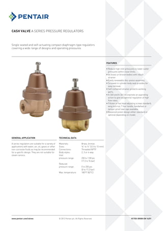
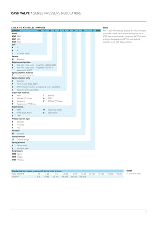
Cash Valve A Series pressure regulators
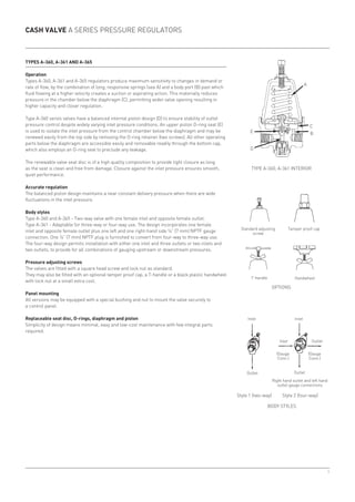
Operation
All A series pressure regulators are supplied with the requested delivery pressure pre-adjusted at
the factory. Pressure adjustment is accomplished by turning the adjusting screw either clockwise
to increase delivery pressure or counter-clockwise to reduce delivery pressure. For example,
turning the adjusting screw clockwise forces the adjusting spring to act against the diaphragm
assembly and move the internal valve seat to the open position.
When high inlet pressure is applied, it flows into the regulator, through the open seat, up under
the diaphragm and on through the outlet. As the outlet pressure builds up under the diaphragm to
the adjusted psi setting, the downward adjusting spring pressure is overcome and the regulating
valve seat closes to maintain the required delivery pressure.
Models overview
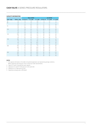
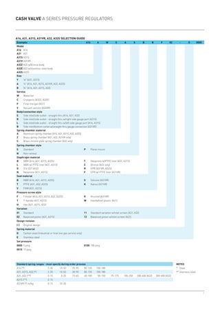
A-16
• Sizes: ¼” or ⅜” (7 or 10.5 mm)
• Body styles:
- Two-way valve with one female inlet and opposite female outlet.
- Three-way valve with one female inlet and opposite female outlet plus a left-hand side ¼” (7 mm)
NPTF gauge connection[1]
.
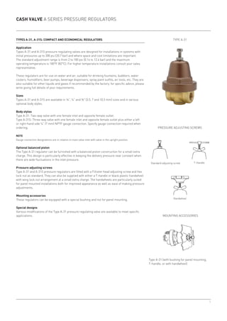
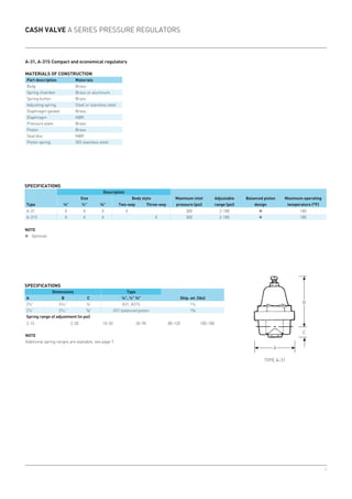
A-31 and A-31S
• Sizes: ⅛, ¼” and ⅜ (3.5, 7 and 10.5 mm)
• Body styles:
- Type A-31: two-way valve with one female inlet and opposite female outlet.
- Type A-31S: three-way valve with one female inlet and opposite female outlet plus either a left or
right-hand side ¼” (7 mm) NPTF gauge connection[1]
.
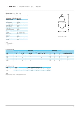
A-360 through A-365
• Sizes: ¼”, ⅜” and ½” (7, 10.5 and 15 mm)
• Body styles:
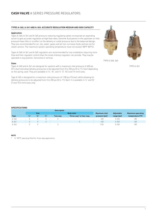
- Type A-360 and A-365 - two-way valve with one female inlet and opposite female outlet.
- Type A-361 - adaptable for three-way or four-way use.
Note
1. Gauge connection designation is in relation to main valve inlet with valve in upright position.
Type A-16 (two-way).
Type A-360, 365
Type A-361
Type A-31](https://image.slidesharecdn.com/pressureregulatorvalvecashaseries-160727140818/85/Pressure-regulator-valves-for-industrial-process-control-2-320.jpg)


The document outlines the specifications, applications, and operational features of the Cash Valve A series pressure regulators manufactured by Pentair. These regulators, designed for a variety of fluids excluding steam, are made from brass or bronze and are available in several models suited for different inlet and outlet pressure requirements. Key features include easy pressure adjustment, a self-cleaning strainer, and various body styles for flexible installation.


