Download to read offline


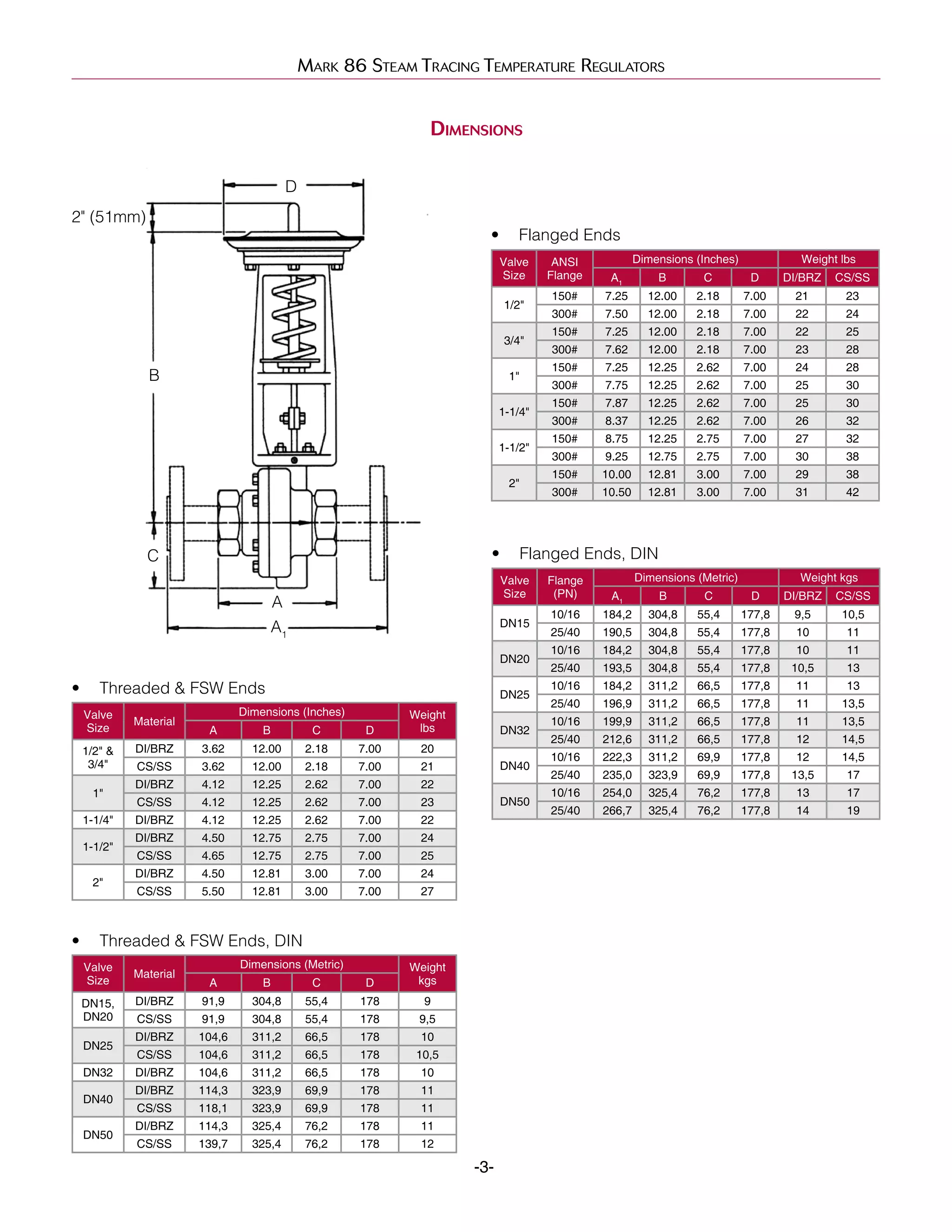
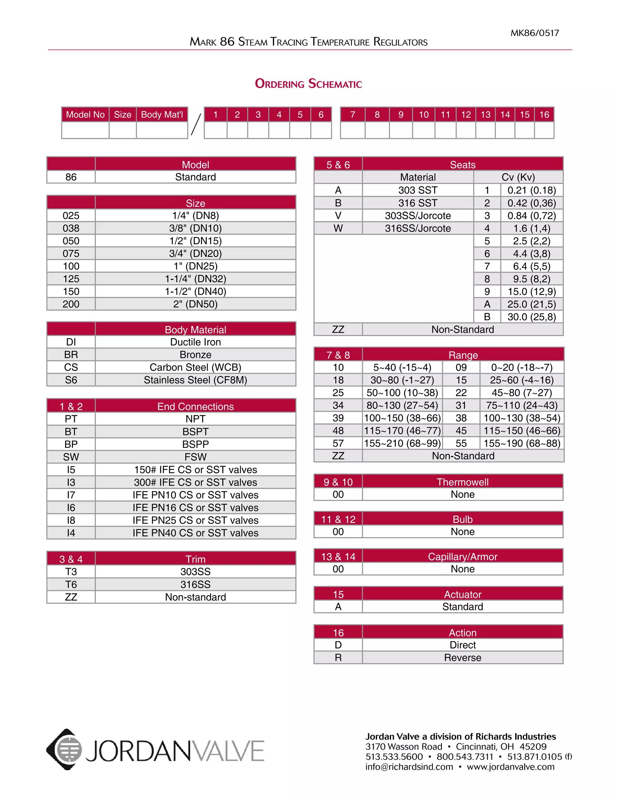

The Mark 86 Series Steam Tracing Temperature Regulators are designed to control steam tracing lines in response to ambient temperatures, preventing the freezing of outdoor instruments and pipelines. The regulators feature a sealed welded actuator providing longer service life and can be configured for normal open or closed operation. This document details specifications, materials, dimensions, and ordering information for the regulators.


