SlideShare a Scribd company logo
1 of 73
Ladle refining furnace

Contents
1. Introduction                                     6. Sampling


2. Basic Metallurgy                                 7. Operative Practice


3. Heating


4. Stirring


5. Alloys and Slag builders


                       CVS MAKINA - LF TRAINING - D.E.                      1


                                     Introduction


                       CVS MAKINA - LF TRAINING - D.E.                      2


                                                                                1
Introduction


The LF represents a reality in a large number of steel production lines since
its origins date back to the era in which ladle furnace were equipped with
slide gates and porous plugs.
Thanks to the possibility of treating steel in the ladle, the melting furnace is
no longer subject to long refining times and its production capacities have
been accelerated while rendering time management much more flexible with
respects to the CCM.
In recent years all the above has contributed, thanks to a proper use of this
machine, to a significant improvement, not only form a production point of
view but also from a quality and economic point of view thus achieving
interesting levels.


                        CVS MAKINA - LF TRAINING - D.E.                            3


                                      Introduction


   Some theoretical indications with extensive operating description
   provided here below will show how this equipment, if use correctly, can
   provide a decisive support to three main points, namely:


   • Productivity
   • Quality
   • Cost reduction


                        CVS MAKINA - LF TRAINING - D.E.                            4


                                                                                       2
Introduction


The LF is designed to ensure the following main purpose:
1. Easier secondary metallurgy operations
2. Optimal and through homogenisation process
3. Accurate analyses for the CCM
4. Improved castability in the CCM
5. Achievement of cleaning steel
6. Reduction of the EAF consumption figures
7. Reduction of the EAF operating times
8. Increase in the productivity of the whole line EAF-LF-CCM


                     CVS MAKINA - LF TRAINING - D.E.                                 5


                                   Introduction

1. Easier secondary metallurgy operations
The possibility of decreasing the S content level down to very values
(ex.0.003%) is of basic importance. This would occur under ideal conditions.
However the Key to a correct DeS process (normally reaching a delta ranging
from 50% to 80%, between the S value during the tapping phase and the final
S value of the CCM tundish) is the compliance with the three basic parameters,
namely:
• no slag is tapped from the EAF into the Ladle
•the value of the free oxygen is lower than 30 ppm
•during tapping and subsequently in the LF a slag is formed with a ratio higher
than 2.1.
Provided that the slag is properly prepared (basic and sufficiently fluid) the
second positive effect is obtained. In fact, under this condition, many oxide and
a large number of inclusion rise to the surface of the fluid slag thus leaving the
steel very clean.

                     CVS MAKINA - LF TRAINING - D.E.                                 6


                                                                                         3
Introduction

2. Optimal and through Homogenisation Process
Homogenisation is a very important process and it is achieved trough porous
plugs, the number of which depends on the ladle size (one for ladle up to 80t,
and two for larger ladles).
The homogenisation guarantee the following:
• High and regular speeds for chemical combinations
• Elimination of temperature pick-up
• Very representative samples for analysis
• Acceleration of inclusion decantation
• Required physical contact between steel and slag


                     CVS MAKINA - LF TRAINING - D.E.                                 7


                                   Introduction

3. Accurate Analyses for the CCM
In order to obtain such result, it is recommended to observe very carefully the
following conditions:
•make sure the the stirring is correctly carried out at all times and that the
adjusted of the argon and nitrogen flow rates and pressures are such that a
steel ‘’bare eye’’ achieved with a diameter not exceeding 10-12 inches with
respect to the slag
•Always carry out the first analysis two minutes after beginning to heat the steel
with electric arc when the slag is sufficiently liquid
•When sampling the steel for the analysis (see above) check the level of free
oxygen in the steel
•Keep under control the operations by following the corresponding steel making
standard report


                     CVS MAKINA - LF TRAINING - D.E.                                 8


                                                                                         4
Introduction

4. Improvement Castability in the CCM
A considerable increase in the steel castability can be achieved provided that:
• the tundish and nozzle are sufficiently hot, with the ladle having necessarily
received the steel from the EAF at a standard temperature during tapping
• the heating conditions are the same as those of the tundish without tapping
slag from the furnace
• all other basic requirements are complied with
The above result can be achieved provided that:
•the steel temperature is very constant time
•the steel is much cleaner and free from macro inclusion
•the steel is chemically free from considerable quantities of oxides


                      CVS MAKINA - LF TRAINING - D.E.                                  9


                                    Introduction

5. Achievement of cleaner Steel
The simple fact that the treatment time, depending on the steel grade, lasts
from a minimum of 25-30 min to a standard of 50-60 min, obviously leads to the
decantation of impurities.
This phenomena, that occurs due to the difference of specific weights, may be
considerably accelerated, provided that the use is correctly, by varying the
following factors:
•temperature changes above 80°C as compared with the Tliq
•calibrated stirring according to the current position, as to the specific operating
procedure
•use of correct slag viscosity


                      CVS MAKINA - LF TRAINING - D.E.                              10


                                                                                           5
Introduction

6. Reduction of the EAF consumption figures
7. Reduction of the EAF operating times
The decisive factor is that, by means of this system, the melting furnace is
released from all the aspects relevant to the so-called refining process. As
results,being just a melting machine, its functions will be the creation of a fixed
matrix as far as analyses and temperature are concerned, without obviously
pouring slag into the ladle.
By saving time and being able to tap at relatively low temperatures, it follows
that for the EAF there will be a considerable saving of :
real time, power supply, electrode and refractory consumption
Several times, by acting on the rate and on the repeatability, for long CCM
sequences (from 5 up to 50) in progressive scale, the EAF performance can
reach optimal levels thus reducing the relevant costs and improving
performance levels to unexpected but actual results.


                      CVS MAKINA - LF TRAINING - D.E.                                 11


                                    Introduction

8. Increase in the Productivity of the whole Line (EAF-LF-CCM)
Assuming to have a secondary metallurgy station it becomes easier to manage
programs, times,rate and conditions by gradually optimising them and, in the
vent of any delays of one of the production units, to use the LF as a buffer,
which is able to cope with the problems caused by the CCM as well as EAF.
Thanks to this natural flexible operation mode, sequence casting becomes
easier with consequent increase in the productivity and reduction of the
relevant costs.
Another major factor, often considered as an effect, consists in the
improvement of the quality level which, in the rolling process and in the other
finishing phases, in addition to favouring high productivity levels, it considerable
lowers the quantity of rejects.
Substantially, this is a very strategic aspect that may easily result into positive
returns as far as sponsoring is concerned but also as regards immediate
economic profits.


                      CVS MAKINA - LF TRAINING - D.E.                                 12


                                                                                           6
Basic Metallurgy

LIQUIDUS AND SOLIDUS TEMPERATURE.
Pure Fe melts at 1536°C.
If the liquid iron contains other elements ,it will no longer have a fixed melting
point, but will rather melt within a solidification interval,determined by a solidus
and liquidus temperature. The solidus temperature is of limited importance to
us whereas the liquidus temperature is all the more important..
We use the T.liq as a reference level on top of which we add a certain over
temperature for defining the optimum casting temperature.
Fe is typically alloyed with Carbon, which changes the melting point from pure
iron to a liquidus line.


                       CVS MAKINA - LF TRAINING - D.E.                                 13


                            Basic Metallurgy


                       CVS MAKINA - LF TRAINING - D.E.                                 14


                                                                                            7
Basic Metallurgy

Our method of calculation considers 1536.6°C as the solidification
temperature of pure iron,
because of the presence of alloyed and residual elements in the steel,
which have the effect of decreasing the temperature,
it is necessary to take into consideration the chemical composition of the steel
in order to compute its liquidus temperature,
Our logarithm, widely used for calculation, is based on statistically evaluated
results of metallurgical laboratories.


                        CVS MAKINA - LF TRAINING - D.E.                                 15


                             Basic Metallurgy


             Tliq = 1536,6 - (%C * Z) - (%E * W)


                                                          Tliq = liquidus temperature
    C%             Z            E         W
0.06-0.10          89           Si        8               %C = carbon content
0.11 -0.50         88           Mn        5
0.51-0.60          86           P         30              Z = multiplying factor for
0.61-0.70          84           S         25              carbon
0.71-0.80          83           Cr        1.5
0.81-0.90          82           Ni        4               %E = content of elements
                                Cu        5               listed in the table
                                Mo        2
                                V         2
                                                          W = multiplying factor for the
                                Al        5.1             listed elements


                        CVS MAKINA - LF TRAINING - D.E.                                 16


                                                                                             8
Basic Metallurgy

 Spectrometer:
 nowadays ,this instrument is very fast in supplying the steel analysis for all the
 necessary and required elements, its principle is based on the basic
 assumption that each chemical element has its individual specter, with precise
 bands (similar to those found on a supermarket label) whilst the relevant
 percentage is determined in relation to the proportional light emissions. Within
 two minutes the sequences of the desired and required elements will be
 directly displayed on the video screen and is generally based on the following
 criteria…
 Standard order:
 C Mn Si P S Cu Ni Mo Sn Al As Ti V Nb W Ca B Co Te
 of course, the calibration and the reading curves, will be a function of the
 required analysis and of the usual percentages of certain elements.
 All this will be carried out through tests of samples with known chemical
 analysis to obtain the conversion factors.


                     CVS MAKINA - LF TRAINING - D.E.                               17


                           Basic Metallurgy


Finally the L.F. Operator will obtain some figures that should be interpreted as
follows.
• 0.01% is equivalent to one centesimal point,therefore saying that c=18 is the
same as c=0.18% or mn =67 is the same as saying mn =0.67% .This system
is valid for the following elements c.Mn.Si.Cu.Ni.Cr. W. Mo. And co.
• 0.001 is equivalent to one millesimal point ,therefore saying that p=29 is the
same as saying p is 0.029,or al,=55 is the same as al=0.055.This system
applies to the following characteristics:::;p.S.Al.Sn.As.Ti.Nb.B.V.Ca.Pb.Te
etc….
• O2..N2 and H2 as already stated ,one ppm (i.e. one part per million) is
equivalent to 0.0001% reference is made to carbon pick -up.


                     CVS MAKINA - LF TRAINING - D.E.                               18


                                                                                        9
Basic metallurgy

Secondary metallurgy is divided into two steps.
• Operating steps
• Techniques
The basic steps are as follows
1. Preventing slag from leaving the primary melting units.
2. Mixing and homogenisation.
3. Heating.
4. Charging of additives.
5. Vacuum treatment..
6. Shrouding of the steel flow in the ladle and Tundish.
7. Electromagnetic stirring during continuous casting.


                      CVS MAKINA - LF TRAINING - D.E.                            19


                 Secondary metallurgy

 CORRESPONDING TECHNIQUES.
 1. Stirring gas treatment with porous plugs, lances or with the aid of
 electromagnetic stirring
 2. Hopper fed alloying elements ,deoxidation agents or slag forming agents.
 3. Lance injected solids
 4. Vacuum degassing with the aid of various techniques
 5. Spooling in of cored wire
 6. Ladle furnace with electric arc
 The various methods and processes of secondary metallurgy are frequently
 combinable, giving rise to precisely defined sequences ,for the production of
 special steel grades and for the compliance within defined tolerances of the
 alloying elements or additions


                      CVS MAKINA - LF TRAINING - D.E.                            20


                                                                                      10
Basic Metallurgy


 GENERAL CHARACTERISATION
 Slag is not an undesired by-product of refining.
 On the contrary, it is an indispensable prerequisite for it.
 The slag layer functions like a reservoir which can absorb and retain a tramp
 element like S, but also in case the process is not properly controlled, return
 the element to the bath and ruin the efforts of refining.
 Refining slags normally have CaO as the major constituent,and such slags
 are referred to as basic slags, in exceptional cases Acid slags with SiO2 as
 the main component are used , mainly for the removal of manganese from
 low manganese steels..


                     CVS MAKINA - LF TRAINING - D.E.                               21


                           Basic Metallurgy


BACKGROUND
The reasons for preventing the primary furnace slag from entering the ladle
furnace are :
• minimizing the phosphorus reversion into the steel
• minimizing the amount of oxygen entering the ladle.


                     CVS MAKINA - LF TRAINING - D.E.                               22


                                                                                        11
Basic Metallurgy


LIMITING THE LINING WEAR.
The primary furnace slag contains more or less phosphorus pentoxide P2O5,
bound to the lime as calcium phosphate.
The P content depends on the raw material used in the primary furnace.
Clean scrap and /or reduced pellets ( sponge iron made from pure ore ) give
hardly any phosphorus in the steel (or in the slag) made in the arc furnace.
The content of phosphorus pentoxide in the slag can vary from less than 1% to
more than 20%.
The acceptable amount of slag entering the ladle furnace is thus, amongst other
things,dependent on the phosphorus level in the slag


                      CVS MAKINA - LF TRAINING - D.E.                               23


                            Basic Metallurgy


The crude steel leaving the primary furnace is in general oxidized. The
oxygen content being a function of the carbon level.
Since there is a relationship between the the oxygen content in the steel and
in the slag respectively, this means that the furnace slag can be more or less
aggressive to the refractory lining .
The oxygen exists in the slag as iron oxide Fe0, fluxes, MgO and CaO which
are the main constituents of the refractory lining .
The more of this slag coming into the ladle furnace, the greater is thus the
risk of lining wear. This type of slag also has a negative effect on the yield of
added alloys, especially those having a strong affinity for oxygen,such as Si,
Al, Ti, etc.
It is important in most cases to minimize the quantity of furnace slag entering
the ladle furnace.


                      CVS MAKINA - LF TRAINING - D.E.                               24


                                                                                         12
Basic Metallurgy

On the other hand there are examples where large slag volumes are
desirable in the ladle furnace, such as when desulphurising.
This is in general fulfilled by adding adequate amounts of lime.
If however, the P content in the primary furnace slag is sufficiently below the
critical level, it is possible to let this slag ,or part of it ,remain in the ladle
furnace to take part in the subsequent refining (Desulphurization) which will
take place there.
In practice the slag during primary melting , for instance in the arc furnace is
allowed to run off during the final stages of the melting. At this stage the slag
usually contains a high iron oxide content


                        CVS MAKINA - LF TRAINING - D.E.                               25


                              Basic Metallurgy


  After tapping into the ladle ,the steel is normally pre-deoxidized but it still
  contains a high oxygen content ,and the oxygen potential of the slag is very
  high,.In order to order to prevent the primary furnace slag from entering the
  ladle furnace there are three possible ways to deslag:


  1. DESLAGGING OF THE PRIMARY FURNACE BEFORE TAPPING.
  2. DESLAGGING OF THE LADLE BEFORE STARTING TREATMENT..
  3. RELADLING.


  The method used mostly today is,is to deslag before treatment,this can be
  done by tilting the ladle,.simply running off via a slag spout,or by the most
  popular method of using a slag rake


                        CVS MAKINA - LF TRAINING - D.E.                               26


                                                                                           13
Basic Metallurgy

Modern ladle cars ,have been fitted with a hydraulic system making it
possible,to tilt part of the ladle car,and with the use of the slag rake make it
very easy to deslag. A slag spout is necessary in order to protect the ladle
flange and to prevent the build up of slag on the brim of the ladle. Which would
jeopardize a satisfactory seal between the roofs and the ladle furnace..
The spout can be attached by a hydraulically operated device or placed on
and removed from the ladle with the help of a crane.


                       CVS MAKINA - LF TRAINING - D.E.                               27


                            Basic Metallurgy


   CHEMICAL COMPOSITION.
   Refining slags are composed of the main constituents from the Ca0-SiO2-
   Al2O3 - MgO system.
   CaO comes from the added lime and the slag should normally be saturated
   with it.
   SiO2 and Al2O3 come from the primary furnace slag,deoxidation products
   and,to some extent from the refractory wear, Al2O3 is also an important flux in
   many synthetic slags.
   The MgO content normally comes from the dissolution of MgO in the ladle
   and roof refractories.


                       CVS MAKINA - LF TRAINING - D.E.                               28


                                                                                          14
Basic Metallurgy


MgO may be added as pure material or as dolomitic lime for reducing
ladle lining wear,Its content is normally 6 to 8% in refining slags..
Addition of 5 to 10% of CaF2 may be needed for fluxing the slag.
FeO, MnO and Cr2O3 appear, as “tramp” constituents and their presence
is detrimental for the steel quality.Their sum should not exceed 1.0 to
1.5%.
S appears as CaS and is picked up from the metal.
P is practically absent in ladle refining slags,due to the low oxygen
activity..
TiO2 may appear as a result of dissolution of bauxite refractories.It is also
detrimental for steel quality.


                    CVS MAKINA - LF TRAINING - D.E.                               29


                         Basic Metallurgy

Refining slags may have a different composition depending upon whether
Si-killed,or Al -killed ( Si free) steels are being produced.
Si -killed steels that shall be continuously cast into billets require that the
slag,have a low Al2O3 ,content in order to avoid ,tundish nozzle clogging.
Al -killed ,Si free steels require that the SiO2 content be low so as to
minimize the Si pick-up from the slag by the metal

     CaO                        56-62% CaO                       56-62%
     SiO2                        6-10% SiO2                      15-20%
     Al2O 3                     20-25% Al 2O3                      5-8%
     FeO+MnO+Cr2O3                 <2% FeO+MnO+Cr2O3                  <2
     MgO                           6-8% MgO                        6-8%
     S                        0.3-2.0% S                          0.3-1%


                    CVS MAKINA - LF TRAINING - D.E.                               30


                                                                                       15
Basic Metallurgy


                    CVS MAKINA - LF TRAINING - D.E.                            31


                         Basic Metallurgy


Slags for steel refining must have not only the right chemical character but
also the right liquidus temperature, so that they are readily liquid but not
overly aggressive at steelmaking temperatures.
Slags have liquidus and solidus temperatures just like metals.In contrast
to metals however, it is much more complicated to predict these
temperatures as a function of the chemical composition, because there is
a much stronger interaction between the slag constituents than between
metal constituents.
Even if a slag is liquid,it may have such a high viscosity,that further
addition of flux is required.Generally speaking ,additions of Al2O3 or CaF2
are used to regulate the fluidity of slags on a rather empirical basis.


                    CVS MAKINA - LF TRAINING - D.E.                            32


                                                                                    16
Basic Metallurgy

HEAT CAPACITY
The heat capacity for the aforementioned slags is 0.41kwh/(tonne,K) and
practically independent of temperature within the 1500 - 1700 °C range.


DENSITY
The density of refining slags can be calculated with fair precision on the
basis of empirical models.Densities for the two aforementioned slags are
in the 2.7 to 2.8 kg/dm3 range for temperatures within the 1500 to
1700°C.


                       CVS MAKINA - LF TRAINING - D.E.                           33


                             Basic Metallurgy


                                   S te e l D e n sity
                         A s F u n c tio n o f T e m p e ra tu re
                            0 .1 2 % C , 0 .2 5 % S i, 0 .7 5 % M n
              D en s ity, kg /d m 3


              6 .9 5


              6 .9 0


              6 .8 5
                          1 ,5 5 0        1 ,6 0 0        1 ,6 5 0    1 ,7 0 0
                                        T em p eratu re, C


                       CVS MAKINA - LF TRAINING - D.E.                           34


                                                                                      17
Basic Metallurgy

BASICITY
The single most important numerical index which summarizes the
composition of a slag and serves as a single parameter with which its
chemical character can be correlated, is the (BASICITY INDEX.)
Basicity is not a univocal notion at least 14 different definitions have been put
forward over the years.
The simplest and most widespread definition is the one by Herty in the 1920,s
called V -RATIO and defined as :

                    V-ratio =(WT-% Ca O ) / ( WT-% SiO2 )

The V-ratio ignores the effects of the other basic (FeO,MnO, MgO, 0 and acid
( Fe2O3,Al2O3,P2O5) OXIDES.More complex definitions abound but do not
add any further substance to the discussion that follows.We shall therefore
limit ourselves to the use of V ratio for basicity.

                     CVS MAKINA - LF TRAINING - D.E.                                35


                          Basic Metallurgy


The V ratio cannot be successfully used for accurately predicting
desulphurisation capacity but is merely and expedient way of roughly
characterizing a slag as regards its refining capacity
The V ratio in refining slags lies normally in the 1.8 to 3.5 range.


                     CVS MAKINA - LF TRAINING - D.E.                                36


                                                                                         18
Basic Metallurgy

SULPHIDE CAPACITY
One of the most important tasks of refining slag is to absorb and hold S as
sulphide. S
Slag property to hold S is called Sulphide Capacity and it is defined as
Cs = Ks * (%S) * [aO ] / (fS * [%S ]             where log Ks = (935/T - 1.375)
Cs can be calculated from (%S) content in the slag, oxygen activity [aO ] in
the steel, sulphur concentration [%S ] in the steel, activity coefficient fS and
the temperature.
The expression for sulphide capacity can be witten as the following form that
is called sulphur partition ratio Ls
                        Ls = (S%)/[S% ] = Cs * fs / (Ks * aO)
and looking the above formula we understand the factors that promote the
desulphurisation.


                            CVS MAKINA - LF TRAINING - D.E.                        37


                                 Basic Metallurgy


                          Interaction of Carbon on Sulphur
                                Activity Coefficient f S
                    As Function of C Content at 0.03 % S, 1600°C
                        Activ ity Coefficient   fS
                    5


                    4


                    3


                    2


                    1


                    0
                        0          1        2      3          4   5
                                           C Content, %


                            CVS MAKINA - LF TRAINING - D.E.                        38


                                                                                        19
Basic Metallurgy


REFINING REACTIONS.
Refining of steel normally means the removal of one or several elements
from the metal bath.Such refining is brought about by slag metal
reactions,gas-metal reactions or metal bulk reactions.
Refining of the following elements will be discussed: S,H,N,C,O.
In addition fundamental aspects of calcium treatment will be discussed.
Refining of a particular element may be performed by one or several of the
above mentioned reactions.Desulphurisation is a typical slag -metal reaction
whereas deoxidation can be carried out as a metal bulk reaction,slag -metal
reaction ,or even a gas -metal reaction.


                    CVS MAKINA - LF TRAINING - D.E.                              39


                         Basic metallurgy


Removal of S from steel into the slag is conventionally illustrate by the
reaction
                            [S] + CaO       CaS + [O]


To achieve a good desulphurisation it is first of all necessary that three
fundamental conditions be satisfied.
1. Basic Slag.
2. High Temperature (60-80deg greater than delta T sl).
3. De -oxidation of the bath(aO2 less than 40ppm).
The stirring of the bath and the reactivity of the slag are important to speed
up the formation of Ca Sulphide.


                    CVS MAKINA - LF TRAINING - D.E.                              40


                                                                                      20
Basic metallurgy


 Desulphurisation is mathematically represented by the formula

                              S final = S initial * e -ks *(A/V)* t
 A = bath area m 2

 V = metal volume m 3
 Ks = desulphurisation rate constant m/min
 t = process time


 Ks values depending on the stirring power and we can consider :
 Ks in the LF = 0.08 (0.8-1.2 Nl/ton min)
 Ks in the VD = 0.20                                                                More details


                                                                                     Next lesson


                        CVS MAKINA - LF TRAINING - D.E.                                            41


                              Basic metallurgy

Desulphurisation

Several elements that occur as tramp elements or alloying elements in the metal bath can move
between slag and metal. From a ladle refining point of view, the most important element in this
respect is S, and refining of it will therefore be described in rather detail.

The partition of an element between slag and metal is controlled by the chemical environment,
principally oxygen activity and slag basicity, and can be predicted by use of thermodynamic
calculation models.


                        CVS MAKINA - LF TRAINING - D.E.                                            42


                                                                                                        21
Basic metallurgy


  Removal of S from a metal bath into the slag is conventionally illustrated by the reaction:

                                            S + CaO      CaS + O

  A basic slag is considered be completely ionised so that we preferably write the desulphurising
  reaction:

                                             S + O2-     S2- + O

  By writing in this manner, we also confirm the fact that not only CaO but also MgO, FeO, Na2O
  and other oxides to a varying degree contribute the oxygen ions necessary for the reaction.

  We have already defined an expression for the S partition between slag and metal (see section on
  sulphide capacity). Now we want to predict the final sulphur content in the metal, however, for
  which purpose we must know the specific slag weight, i e kgs of slag per ton of metal, slag
  sulphide capacity, the initial concentration of S in the slagbuilders and in the metal and, finally, the
  S activity coefficient in the metal.
  We assume that the total amount of S remains constant, i e that what has left the metal will be
  found in the slag.


                            CVS MAKINA - LF TRAINING - D.E.                                                  43


                              Basic metallurgy

It is then possible to derive the expression:

                                             [ %S ]*W             (      )
                                                                 + %S0 *W slag
                              [ %S ]=
                                    final
                                                 0       steel

                                                     W steel +LS *Wslag

where ‘W’ denotes weight.

At this point, we substitute L S for C S * fS / (K S * a O) as described earlier in the discussion about
Sulphide Capacity. That brings us to the expression for final, equilibrium S content in the metal :

                                               %S0 *W steel           %S0 *W slag
                               %Sfinal
                                             W steel CS* fS / KS* a O *W slag

The activity aO can easily be calculated or measured in metals of very varying composition; fS is
likewise easily calculated using Wagner’s formalism; C S can be calculated from slag analysis and
temperature. Weights of metal and slag are already known.
We therefore have all necessary information for calculating the maximum possible extent of
desulphurisation. The figure shows an example with equilibrium sulphur content in the metal as
function of slag V-ratio.


                            CVS MAKINA - LF TRAINING - D.E.                                                  44


                                                                                                                  22
Basic metallurgy

It is evident that the V-ratio must be at least greater than 2 in order that a good desulphurisation be
attained.
Referring back to the phase diagram CaO - SiO2 - MgO - Al2O3, the best desulphurisation results
are attained with slags which are just saturated with CaO.

The fact that a considerable desulphurisation is possible does not necessarily mean that a low
final S content will actually be reached. The exchange reaction between metal and slag takes time
and is mainly influenced by the stirring and mixing intensity.

Desulphurisation is mathematically represented by the well-known exponential function


                             CVS MAKINA - LF TRAINING - D.E.                                              45


                               Basic metallurgy

                                                            kS * A / V * t
                            %S       % S0      %S * e                        %S


 where     %S     =   S content at time ‘t’
           %S0    =   initial S content in metal
           %S     =   S content after infinite time (equilibrium content)
           kS     =   desulphurisation rate constant, m/min
           A      =   stagnant metal-slag interfacial area, m 2
           V      =   metal volume, m 3
           t      =   desulphurisation time, min.

 In the above function, we know everything except for the rate constant kS . The rate constant can
 be approximated from the gas stirring flowrate, temperature and ambient pressure but such
 models are not accurate. Measurement is actually the best method of determining the rate
 constant for various operational cases such as heating in ladle furnace and treatment under
 vacuum.


                             CVS MAKINA - LF TRAINING - D.E.                                              46


                                                                                                               23
Basic metallurgy


                        R a te o f D e s u lp h u ris a t io n in L F a n d V D
                     a t In itia l S 0 .0 3 0 % , E q u ilib riu m S 0 .0 0 8 %

                    S C o n te n t, %
                    0 .0 3 5
                                                 LF         VD      E q u il i b ri u m
                    0 .0 3 0                  k S 0 .0 5 k S 0 .2 0   0 .0 0 8 %

                    0 .0 2 5

                    0 .0 2 0

                    0 .0 1 5

                    0 .0 1 0

                    0 .0 0 5
                               0    10        20        30          40      50     60     70
                                         D e s u lp h u r is a tio n T im e , m in


                               CVS MAKINA - LF TRAINING - D.E.                                        47


                                    Basic metallurgy


Evaporation of Metallic Constituents

Metallic constituents of a steel bath have vapour pressures that can relatively easy be calculated
as described previously.

If we let gas bubbles pass through the melt, they will therefore pick up evaporated constituents,
theoretically up to the saturation point at which the partial pressure reaches equilibrium with the
activity of the element in the liquid metal. Kinetic constraints may prevent the bubbles from
becoming saturated as they rise, however.

The metallic vapours condense and, generally, oxidise above the metal bath to form what we
simply experience as dust.


                               CVS MAKINA - LF TRAINING - D.E.                                        48


                                                                                                           24
Basic metallurgy


Vacuum treatment and electric arc heating are two well-known cases of generous evaporation and
dust formation, although for different reasons.
Vacuum treatment generates substantial quantities of dust mainly because the inert gas bubbles
passing through the metal expand strongly due to the low pressure above the metal bath and
therefore pick up much evaporated solutes.
Electric arc heating generates much dust, principally because the temperature of the electric arcs
is extremely high which induces a lot of evaporation.

Zinc and lead have very high vapour pressure at steelmaking temperature and may therefore be
found in large quantities in dust. Such dust must be disposed of under safe conditions so as not to
contaminate environment.
Manganese has got a comparatively high vapour pressure. Elevated levels of MnO are therefore
always found in dust from secondary metallurgy installations. Vacuum treatment may produce a lot
of pyrophoric, condensed Mn particles in the suction line.


                               CVS MAKINA - LF TRAINING - D.E.                                        49


                                      Basic metallurgy


                                                        Examination of dust from ABS in
                                                            the VD dust separator


  E v a p o r a tio n o f M e ta ls                          Element     Content, wt-%
  a n d D u s t G e n e r a tio n                                Fe                4-6
                                       O2                        Mn              10-15

                          D ust                                  Cr              0-0.3
                                                                 Ni              0-0.1
                                                                 Cd            0-0.003
                                                                 Cu            0.5-0.7

                         pFe
                                                                 Zn              15-30
              Fe                                                 Pb                2-6
                                                                 CaO             10-12
        T        Mn            pM n
                                                                 SiO2              1-5
                                                                 Al2O3           0.2-3
                            pCr
                Cr                                               MgO             15-35


   S tirr in g G a s


                               CVS MAKINA - LF TRAINING - D.E.                                        50


                                                                                                           25
Basic metallurgy

                     C alc ulated E v aporation of Elem ents as
                 F unction of P ressure During Vacuum D egassing
                              1600 C , 1 % M n, 0.05 % A l, 25 m in utes

              Ev aporated A m ount, kg/ton


                 0 .1 0                                                              Mn
                                                                                   kg/ton ne

                 0 .0 8                                                               Fe
                                                                                   kg/ton ne

                 0 .0 6                                                               Al
                                                                                   kg/ton ne

                 0 .0 4                                                              T o tal
                                                                                   kg/ton ne

                 0 .0 2

                      0
                          0       1     2      3      4     5      6       7   8       9       10
                                                   P res s ure, torr


                          CVS MAKINA - LF TRAINING - D.E.                                           51


                                  Basic metallurgy


FLUSHING OF DISSOLVED GASES BY GAS PURGING
The fact that the partial pressure of a dissolved gas depends upon its
activity in the metal, and hence upon its concentration, can be taken
of for flushing a dissolved gas out of the metal.
When the metal bath is flushed by an inert gas , for example Argon, the
atoms of the dissolved gas(-es) will recombine at the inert gas bubble
surface and escape into the bubbles.There, the dissolved gas builds up a
partial pressure which approaches equilibrium with the activity of the
dissolved solute. Taking nitrogen for example
2[N ]    2N      N2


                          CVS MAKINA - LF TRAINING - D.E.                                           52


                                                                                                         26
Basic metallurgy


The volumes of purging gas and dissolved gas in a bubble are proportional to
their respective partial pressures so that
Vdiss/Vpurge =Pdiss/ Ppurge
furthermore ,the total pressure is equal to the sum of the partial pressures of
dissolved gas(es) and purging gas according to
P=Pdiss +Ppurge                         Flushing of Dissolved
                                        Gases by G as Purging

                                        Layer Of S urfactant


                                                2N             p N2


                                          T        2H            p H2


                                         Stirring Gas

                     CVS MAKINA - LF TRAINING - D.E.                              53


                          Basic metallurgy

DEOXIDATION.
Deoxidation is the process by which the content of dissolved oxygen is
reduced in the metal.One distinguishes between three different techniques
for bringing about deoxidation
1. PRECIPITATION DEOXIDATION
2. TOP SLAG DEOXIDATION.
3. VACUUM CARBON DEOXIDATION.


                     CVS MAKINA - LF TRAINING - D.E.                              54


                                                                                       27
Basic metallurgy

 PRECIPITATION DEOXIDATION - REMOVAL OF SLAG INCLUSIONS.
 Precipitation deoxidation is by far the most common deoxidation method.
 As the name suggests,a deoxidiser normally AL or Si is added to the
 metal bath. Upon addition and mixing, the dissolved oxygen will react
 with the added d.the combination of oxidizer so as to produce oxides
 which precipitate in the melt.
 The precipitation deoxidation in itself does not reduce the oxygen content
 but just transforms the dissolved oxygen into oxidic oxygen. Next ,the
 oxidic oxygen particles must be removed from the metal bath by flotation.
 Expressed in the simplest way,the respective reactions are,
 Al+O2     Al2O3 and Si+ O2      SiO2


                       CVS MAKINA - LF TRAINING - D.E.                         55


                            Basic metallurgy


The dissolved oxygen content which results from precipitation
deoxidation depends upon the value of the equilibrium constant and upon
the activities of the reactants and the reaction products.
The dissolved oxygen content, is what really concerns us for the sake of
cleanness of the metal. Al2O3 appears as clusters of small, solid, sharp-
edged particles in the metal.
They are easily floated by gas stirring and induction stirring, Si is rarely
used as a single deoxidiser but rather in combination with manganese.


                       CVS MAKINA - LF TRAINING - D.E.                         56


                                                                                    28
Basic metallurgy


The combination of Si and Mn more efficiently reduces the oxygen content
than either one of the elements alone.
The reason is as follows, when using only silicon as a deoxidiser, the
deoxidisation product is pure SiO2 the activity which is equal to unity.
This SiO2, is solid up to 1713°C.
Furthermore the precipitated particles do not stick together like Al2O3
particles but appear as discrete particles in the metal.They are therefore not
easy to flotate after precipitation.
When adding both Si and Mn to the metal bath,both elements will be
engaged in the deoxidation so that the reactions will run in parallel.
Si +2O >>>>>SiO2
Mn + O >>>>>MnO


                     CVS MAKINA - LF TRAINING - D.E.                                        57


                             Basic metallurgy


The reaction products SiO2 and MnO attract one another strongly because
SiO2 is of acid character whereas MnO is of strongly basic.A manganese
silicate will therefore form, in which the activities of SiO2 and MnO are
strongly reduced.

                                 D is s o lv e d O x y g e n C o n te n t in
                                 S i( -M n )- k ille d S t e e l a t 1 6 0 0 ° C
                                           C 0 .1 2 , M n /S i= 3 . 0
                       Oxygen, ppm

                       200


                       150


                       100                              S i o n ly


                        50                              S i- M n

                         0
                             0     0.05       0 .1      0 .1 5          0.2   0.25   0 .3
                                                 S i C o n te n t, %


                     CVS MAKINA - LF TRAINING - D.E.                                        58


                                                                                                 29
Basic metallurgy


One normally aims at an Mn/Si ratio after deoxidation of >3.
This ensures that the manganese formed silicate is liquid at
steelmaking temperatures.
Precipitation deoxidation generates slag inclusions ( in most cases
AL2O3 or Mn -silicates) that must be removed by flotation from the
metal bath.
The picture illustrates schematically how a high, initial dissolved oxygen
content drops much faster than the total oxygen content.
The difference between total oxygen content and dissolved oxygen
content is the oxidic oxygen tied to the deoxidizer in the precipitates.


                         CVS MAKINA - LF TRAINING - D.E.                        59


                                Basic metallurgy

                              Precipitation Deoxidation
                              Floatation of Inclusions
                             Addition of Deoxidiser at Time = 0
     Oxygen, ppm


         80


         60


         40                                     Oxide + Dissolved Oxygen
                     Oxide Oxygen
         20
                  Dissolved Oxygen
          0
              0          5           10         15       20       25       30
                                          Time, min


                         CVS MAKINA - LF TRAINING - D.E.                        60


                                                                                     30
Basic metallurgy

.The metal bath is always exposed to reoxidation,which generates new
precipitates.
Such reoxidation is caused by FeO, MnO and Cr2O3 in the top slag
refractories. It is also caused by direct oxidation with atmospheric oxygen
coming into the metal bath via an open purging eye or via the teeming
stream.


                   CVS MAKINA - LF TRAINING - D.E.                            61


                        Basic metallurgy

                              Deoxidation and
                           Reoxidation Mechanisms
                                Al                    O2


                                        FeO
                                                 O

                                         O

                        Cr2O3     O

                                2Al+3O =>Al2O3


                                Stirring Gas


                   CVS MAKINA - LF TRAINING - D.E.                            62


                                                                                   31
Basic metallurgy


CALCIUM TREATED STEELS
The aim of calcium treatment is in most cases to improve castability, by
modifying the sharp edged, solid Al2O3 particles into spherical liquid calcium
aluminates.
If reoxidation is allowed to take place after calcium treatment, new
unmodified Al2O3 particles will be generated and they will again obstruct the
casting. Precisely for this reason, Ca treatment must ,with few exceptions, be
the very last ladle refining operation, after which the steel must be cast
without delay.
The stirring power and stirring type are of decisive importance for the final
cleanliness of the steel.


                     CVS MAKINA - LF TRAINING - D.E.                             63


                           Basic metallurgy


 Refining by calcium treatment means that the metal bath is treated with
 metallic calcium. This treatment is done to improve the castability and /or
 improve the mechanical properties like isotropy with the steel product.
 Several forms of calcium can be used, for example SiCa ,Ca pellets,and
 CaFe. Whatever the form of Ca used it will immediately vaporize in contact
 with the steel, because the vapour pressure of pure Ca is 1.92atm at
 1600deg.
  Its solubility at 1600 °C and 1atm is only 300 ppm.
 Castability is improved by the reaction between Ca and Al2O3 particles in
 the steel according to:
 3Ca + Al2O3 >>>>>> 3CaO +2Al.


                     CVS MAKINA - LF TRAINING - D.E.                             64


                                                                                      32
A l 2 O 3 -C a O


                        CVS MAKINA - LF TRAINING - D.E.                               65


                             Basic metallurgy


Al2O3 particles are solid and sharp edged at steelmaking temperatures. They are
prone to accumulating in the tundish nozzles and obstructing the steel flow.
By reaction with the formed CaO, the the Al2O3 particles will form liquid spherical
Ca -aluminate particles which flow through the nozzles without obstructing them.
x CaO + yAl2O3 >>>>>>>>>>(CaO)x (Al2O3)y.
Since Ca has such a strong affinity to oxygen and sulphur it can if supplied in
sufficient quantity,react and transform all oxides and sulphides existing in the metal
bath..Sulphides will be transformed to CaS whereas other oxides will be
transformed to CaO and release Mn ,Si etc back to the metal.


                        CVS MAKINA - LF TRAINING - D.E.                               66


                                                                                           33
Basic metallurgy

                  Modification of Non-Metallic
                  Inclusions by Ca Treatment
                Before Ca Treatment              After Ca Treatment
                           sulphides
                              MnS


                                                                      CaS
                                  alumina
                                    Al2 O 3
                                                                 Al2 O
                                                                 CaO
                    silico aluminates
                      Al2 O 3 +MnO                                  Calcic
                         +SiO 2                                   globular
                                                                 inclusion


         CVS MAKINA - LF TRAINING - D.E.                                           67


                 Basic metallurgy


        C h a n g e s in In c lu s io n C o m p o s itio n
         D u rin g In je ctio n o f C a a t 1 6 0 0 °C
         S teel: 0.1 C,0 .2 S i,0 .4 5 M n , 0 .0 3 A l, 0 .0 2 S

% A l2 O 3 in A lum inates, % C aS in In clus ions

    100
                       1 60 0 °C
                       L iq u idu s
      80
                                  A lu m ina in
                                  c alc ium a lu m ina tes , %
      60

      40                                          C aS in
                                               in clu s ion s
                             La titu d e
      20                     inc lu sio ns
                             fully liqu id

        0
            0         20              40           60            80          100
                 Injec ted C a Q uantity, A rbitrary U nits


         CVS MAKINA - LF TRAINING - D.E.                                           68


                                                                                        34
Basic metallurgy

The amount of Ca injected into the steel shall be such that the composition of the
Ca -alluminate falls roughly within the 3(CaO)(AL2O3) to (CaO)(AL2O3) range.
This ensures that the formed aluminates are liquid at steelmaking temperature.
Too little Ca causes insufficient modification and solid inclusions.
Too much Ca generates solid inclusions as well. As the inclusions become
increasingly rich in CaO a point is reached at which Ca starts reacting with the S to
create CaS according to
Ca + S>>>CaS.
This CaS is solid and will obstruct casting nozzles just like Al2O3 particles.
 It is therefore important that the S content be reduced by another method of
desulphurization before Ca treatment in order that CaS will not be formed by direct
reaction with Ca.


                        CVS MAKINA - LF TRAINING - D.E.                              69


                             Basic metallurgy


  As a rule of thumb, the S content should be below 0.010 % before
  Ca treatment.
  The consumption of Ca for modification of slag inclusions is 0.15.to
  0.35 kg.ton (expressed as pure calcium).
  Due to its high vapour pressure and its very limited solubility in
  steel, practically all Ca in the steel after Ca treatment appears as
  oxide or sulphide.
  No significant amount of dissolved Ca remains as a buffer for
  modifying any AL that may be deoxidized after complete Ca
  treatment.


                        CVS MAKINA - LF TRAINING - D.E.                              70


                                                                                          35
Basic metallurgy


If the steel for one reason or another has become deoxidized after
Ca treatment , it will have to be Ca treated again .
Pneumatic injection of Ca ensures that all Ca reaches to the bottom
layer of steel in the ladle.
In case wire feeding is employed for Ca feeding, the wire diameter
and injecting velocity must be selected so as to ensure that the wire
rests the bottom of the ladle before melting and releasing this Ca
vapours.
Ca supply rate should not exceed about 80gr/tonne,min in order that
the bath agitation be contained .


                         CVS MAKINA - LF TRAINING - D.E.                                   71


                                  Basic metallurgy


         C a S i W i r e F e e d r a te a s F u n c t io n o f S t e e l W e ig h t
                           f o r 1 2 m m W ir e D i a m e te r
         F e e d r a t e , m / m in
         260

         240

         220

         200                                                        O d e r m a th
                                                                    D ia 1 2 m m
         180

         160

         140

         120
                0              50           100         150         200              250
                                      S t e e l W e ig h t , to n


                         CVS MAKINA - LF TRAINING - D.E.                                   72


                                                                                                36
Heating

  The electric arc burns between electrode and metal bath at a tempe rature of 4000 - 8000°C. At this
  high tem perature the gas in the arc become s ionised and transform s into a plasm a. The high
  plasma temperature promotes an efficient energy transfer between arc and bath under each
  electrode.

  The electrom agnetic fields in each phase                                  G eneration of Hot-Spot W ear
  exe rt a strong influence on the arcs so that                              A rc D eflection - Hot Particle Jet
  they deflect from vertical orientation and
  incline towards the ladle wall during ea ch half
  cycle. The higher the electrode current and
  the closer the grouping of the electrodes, the
  stronge r the deflection .
  Electrodynamics forces cause the plasma to
  have a very high internal pressure. The arc
  therefore exerts a pressure on the m etal bath
  and creates a dimple.

  The electrodynamics force s in the electric arcs
  generate a gas stream with a ve locity of about
  1500 m/s along the arc.
  The velocity is particularly high during the half
  cycle when the electrode has negative
  polarity.


                              CVS MAKINA - LF TRAINING - D.E.                                                      73


                                                   Heating

The electric arc length is approximately
                                        L arc = Varc (Volt) - 35 (mm)
35 = anode -cathode voltage drop(constant), used for accelerating and
decelerating electron and ions.
                            E le c t r ic A r c L e n g t h a s F u n c t io n o f A r c V o lt a g e
                           A rc L eng th, m m


                                                       G a s S ti r r in g
                             100


                              80


                              60


                              40


                              20                                       In d u c t i ve S ti r r i n g


                               0
                                   40        60          80             100                   12 0      140
                                                        A r c V o lt a g e , V


                              CVS MAKINA - LF TRAINING - D.E.                                                      74


                                                                                                                        37
Heating

   Power input into a ladle furnace is normally limited by the refractory wear
   rate.
   The actual refractory wear rate is a very complex function of,among other
   factors the following :
   Arc power input                                         Arc Power Input Limitation
                                                     Transmission of Heat to Metal Bath
   Refractory type and quality
   Metal and slag temperature.
                                                                            Bath Height,m
   Thermal profile in the refractory lining.
                                                         Arc Power                          Slag-Metal
                                                         2.0 MW/m
   Metal and slag composition.                                                              Interface Level

   Slag thickness.
   Type and power of stirring
   Ladle furnace geometry.
                                                                               Temperature, °C


                       CVS MAKINA - LF TRAINING - D.E.                                               75


                                     Heating


The electric arcs are immersed in a slag which absorbs a large part of the heat
and transfers it to the metal bath.The slag is superheated 50--150k in relation to
the metal temperature.
The metal bath actually cools the slag.
The metal bath must be stirred by gas or inductive stirring so that the transferred
heat becomes homogeneously distributed.
A practical and reasonable approach to dimensioning the electric power supply is
to make it proportional to the heat transferring area.=Bath area


                       CVS MAKINA - LF TRAINING - D.E.                                               76


                                                                                                              38
Heating

Experience shows that an arc power input of up to about 2mw/2 bath area can be
transferred to the metal bath and is tolerable as a dimensioning criterion for the
power supply.
The arc power is not measured but can be calculated.
As a typical value,the arc power is about 84 - 88% of the active power being
supplied by the transformer.
The remaining 12% are lost in resistive heating of the electrical conductors and the
electrodes.
The heating rate as a function of the active power (ie.[Arc power]/0.88) is shown .


                                   CVS MAKINA - LF TRAINING - D.E.                                        77


                                                  Heating

                                  LF H eating Rate vs. Specific Power Input
           9
                   H eating R ate, K/m in
           8

           7

           6
                                                                                W ate rc. roof
           5                                                                      °C/m in

                                                                                 Refr. roof
           4                                                                      °C/m in


           3

           2

           1

           0
               0                  0.05          0 .1              0.15    0.2                    0 .2 5
                                               Ac tive Power, MW /tonne


     Experience shows that an arc power input of up to about 2 MW/m2 bath area can be transferred to
     the metal bath and is tolerable as dimensioning criterion for the power supply.


                                   CVS MAKINA - LF TRAINING - D.E.                                        78


                                                                                                               39
Heating

 The following operational aspects of arc heating will be discussed


 1. Slag composition and thickness
 2. Stirring of metal
 3. Carbon pick -up
 4. Electrode wear
 5. Pick up of gases from the atmosphere
 6. Refractory wear


                        CVS MAKINA - LF TRAINING - D.E.                              79


                                      Heating

The electric arc is a plasma ,the stability of which depends upon the presence
of a conductive and insulating slag layer.
High arc stability is essential for attaining,high average power input and this is
one of the many reasons why a slag layer must always be present during arc
heating..
Metallurgical refining slag are in most cases of basic character i.e.
%CaO / %SiO2 > 2
Such slag have sufficient electrical conductivity.
The more acid slag ,the more pronounced the the tendency of the electrodes to
jump up and down.


                        CVS MAKINA - LF TRAINING - D.E.                              80


                                                                                          40
Heating

If the slag layer becomes excessively thick,say 150 to 200mm ,the slag layer
may become superheated 1800 to 1900 °C ,and heating of the metal bath
virtually cease despite continuous power supply.
In such a case CaO in the slag will react with the graphite in the electrodes
to form calcium carbide according to the strong endothermic reaction
CaO+3C+q>>>>>CaC2 +CO.The carbide dissolves on the slag ,and may
later react with the humidity according to,
CaC2+H2O>>>>>>C2H2+CaO.To form acetylene,which is explosive.Care
should be taken that the slag thickness is properly controlled so as to avoid
carbide formation ..


                      CVS MAKINA - LF TRAINING - D.E.                           81


                                    Heating

  The metal bath picks up carbon from the electrodes.
  The extent of this carbon pick-up depends on the following factors,.
  • Oxygen activity in the metal bath.
  • Metal bath stirring method.
  • Arc length.
  Experience shows that carbon pick-up by a rimming steel,(oxygen activity
  >150ppm) is practically negligible because carbon from the electrodes
  reacts with dissolved oxygen in the metal bath to form CO.
  The situation is different in steels with lower oxygen activity.


                      CVS MAKINA - LF TRAINING - D.E.                           82


                                                                                     41
Heating

Absorbed by the metal.The electrode tip wear is visible as a cavity in
the electrode at the electric arc foot-point.
Fluctuations are provoked by stirring of the metal bath. Gas stirring
provokes a rather unsteady surface whereas inductive stirring ,if
installed provokes a standing w aeve of rather constant profile. The
incidence of metal droplets coming into contact with the electrodes is
greater with gas stirring than with inductive stirring and the carbon pick-
up is higher.The arc length is obviously of decisive importance for the
carbon pick-up.A study on carbon pick -up as a function of arc length
shows that the arc length for gas stirred ladle furnaces must be about
6.5cm in order that carbon pick-up will not exceed 2.0.To 2.5 ppm
min.The corresponding figure for inductive stirred ladles is rather 5.0
cm.


                      CVS MAKINA - LF TRAINING - D.E.                            83


                                     Heating


                       C pick-up during heating
   (ppm /m in)
   30


   20

                                                             C-pick-up
                                                             gas stiring

                                                             C-pick-up
   10                                                         Ind. stir


    0


        0        20             40              60      80                 100
                                Arc leng th [m m ]


                      CVS MAKINA - LF TRAINING - D.E.                            84


                                                                                      42
Heating


Electrode wear is generally described as a combination of tip wear and side
wear.
The electrode wear is roughly proportional to the energy consumption in the
ladle furnace.
The total wear,expressed as kg of graphite per tonne of steel,can be
estimated, to 0.8 to 1.2% of the energy consumption,expressed as kwh/tonne,
thus corresponds to a graphite consumption of 0.48 to 0.72 kg/tonne.


                            CVS MAKINA - LF TRAINING - D.E.                                              85


                                                   Heating


                                                   SIGRI
          Nominal diameter       Lenght     Weight per electrode      Nipples-Kg and dimension AxL
                                  1500        312         Kg             15        215.90-304.80
                 400              1800        376         Kg            20,5       241.30-338.60
                                  2100        445         Kg

                                                        UCAR
          Nominal diameter       Lenght     Weight per electrode          Nipples-Kg and dimension AxL
                                  1500        324         Kg          222 T4     15,9    222.25X304.80
                 400              1800        397         Kg          222T4L     17,9    222.25X355.60
                                  2100        456         Kg
        * weight wthout nipple

                                    Ucar AGX       250-450 diameter mm
        bulk density                                    1.65-1.72 t/m3      kg/dm3 g/cm3
        specific resistance                             4.8-6.0   microohm * m
        flexural strenght                               9.0-12.5 Mpa
        tensile strenght                                6.0-8.5   MPa
        coefficient ot thermal expansion WG             0.5-1.0   microm/°Cm(30-100 °C)
        porosity                                        20-24     %
        thermal conductivity                            210-280   W/m °C

        real density - all fully graphitized material have a real density of about 2.20 to 2.25


                            CVS MAKINA - LF TRAINING - D.E.                                              86


                                                                                                              43
Heating


  Provide premium grade electrodes are being used, electrode consumption is mainly dependent
  on steelmaking process conditions. Current level, power on time, oxidizing electrode surface area
  and tons per hour are the most important parameters influecing electrode consumption.
  Empiriacally developed formula are avalilable to calculate the amount of the two continuous
  electrode consumption process.
  Typical average oxidation and sublimitation rates are :
                          2
  RsubAC = 0.0135 kg/kA hr - per one electrode tip
  Rox = 8 Kg/m2 hr - for the oxidinziing cone of water spray cooled electrodes.

  Calculation of continuous graphite consumption (sublimation)
                                                   I = current per phase (KA)
                  2                                tpo = power on (hrs)
C tip = Rsub * ( I * tpo) / ( 0.454 * P ) [Kg/ton]
                                                   P = productivity (tons/heat)

  Calculation of continuous graphite consumption (oxidation)
                                           A = oxidizingelectrode surface area (m2)
                                           ttap = tap to tap (hrs)
  side = Rox * ( A * ttap) / P [Kg/ton]
                                           P = productivity (tons/heat)


                                     CVS MAKINA - LF TRAINING - D.E.                                            87


                                                        Heating
                                  Specific electrodes consumption performed at Alpha Steel

                                                         Guaranteed values
                           Guarante electrode consumption                                        0.012 Kg/kWh
                           Electrode consumption obtained                                        0.007 Kg/kWh


                                                   Initial weight (Kg)   Final weight (Kg)   delta W (Kg)
  Electrode column 1                                       908                  760               148
  Electrode column 2                                       908                  796               112
  Electrode column 3                                       908                  780               128
  Total weight 1-2-3                                       2724                2336               388
  Total Electric consumption after 18th heats       56800        Kwh
  S.E.C obtained after 18th heats                   0,007      kg/kWh


                                                   Initial weight (Kg)   Final weight (Kg)   delta W (Kg)
  Electrode column 1                                       908                  698               210
  Electrode column 2                                       908                  740               168
  Electrode column 3                                       908                  735               173
  Total weight 1-2-3                                       2724                2173               551
  Total Electric consumption after 28th heats       80700        Kwh
  S.E.C obtained after 28th heats                   0,007      kg/kWh


                                                   Initial weight (Kg)   Final weight (Kg)   delta W (Kg)
  Electrode column 1                                       908                  601               307
  Electrode column 2                                       908                  647               261
  Electrode column 3                                       908                  641               267
  Total weight 1-2-3                                       2724                1889               835
  Total Electric consumption after 39th heats      113800        Kwh
  S.E.C obtained after 39th heats                   0,007      kg/kWh


                                     CVS MAKINA - LF TRAINING - D.E.                                            88


                                                                                                                     44
Heating

There are numerous factors which affect the final nitrogen level
• scrap
•DRI usage
•long arc versus short arc
•tap carbon
•foaming slag practice
•bottom stirring
•tapping
•deoxidation practice
•ferro alloys


                   CVS MAKINA - LF TRAINING - D.E.                   89


                                 Heating


Electric arc heating is potentially cause a substansial pick-up of
atmospheric gases, notably nitrogen

N2        2N    2 [N]

The arc caused the N2 molecule to dissociate to atomic N or ions.

Nitrogen removal is also affected by surface actives elements O
and S.


                   CVS MAKINA - LF TRAINING - D.E.                   90


                                                                          45
Heating


             P ic k - u p o f N it r o g e n a s F u n c t io n
                             o f S la g T h ic k n e s s
N it r o g e n P i c k - u p , p p m
40

30

20

10

 0
     0     20        40       60    80 100 120 140 160 180 200
                               S la g T h ic k n es s , m m
KSC


                     CVS MAKINA - LF TRAINING - D.E.                     91


                                          Heating


                Pick-up o f Hy dro ge n in LF after V ac uu m
                D ega ssing as Fun ction o f He ating T im e
                    H ydro ge n C o nte nt, p pm
            2

         1.8


         1.6

         1.4


         1.2

            1

         0.8
                0                20              40            60   80
                                      H ea tin g Tim e, m in s
          H ea t W e ig ht 17 2 tonn es


                     CVS MAKINA - LF TRAINING - D.E.                     92


                                                                              46
Heating


The refractory wear rate in the ladle,can be characterised as being of two
kinds:
• General slag line wear
It is caused by the gradual dissolution of the slag line, refractory, mainly
MgO in the slag.
• Hot-spot wear
The extent of this wear mainly depends on
    • slag composition
    • working temperature
    • poor stirring
    • electrode regulation


                         CVS MAKINA - LF TRAINING - D.E.                             93


                                            Heating


                      M g O S o lu b ilit y a s F u n c t io n o f
               S la g B a s ic ity a t 1 5 %        A l2 O 3 a n d 1 6 0 0 ° C

         M gO      C o n te n t i n S la g , %
         20
         18
         16
         14
         12
         10
           8
           6
           4
           2
           0
               1        2           3         4           5        6        7    8
                             S l a g B a s i c i t y , % C a O / % S iO 2


                         CVS MAKINA - LF TRAINING - D.E.                             94


                                                                                          47
Heating

Where does the electric energy go ?
• Heating of the steel                                Utilisation of Electric Energy, kWh/tonne
• Fusing of the slag builders.                            100 ton LF, Steelgrade 20CrNi4
                                                                   8.4   Melting Alloys    9.2
• Heating of the slag.                     Fusing Slagbuilders

                                                                                          Metal Heating
                                                                                                          18.2
• Melting of the alloys.
• Resistive losses in power
                                                                                             Slag Heating0.5
 supply systems and electrodes.
• Losses to refractory,                                                                   Resisitive Losses 16.8
                                                            42.4
                                        Refract., Ambient
 roof, off gas and ambient.


The pie chart shows an example of electric energy distribution including
vacuum treatment


                         CVS MAKINA - LF TRAINING - D.E.                                                     95


                                       Heating


Selection of operating point for the ladle furnace.
The ladle furnace operator can set independent variables only, which define
the so called operating point of a ladle furnace..
1. Secondary voltage.
2. Electrode current.
The choice of operating point will then decide what values will be obtained of
the independent variables active, and reactive power, power factor heating
rate ...


                         CVS MAKINA - LF TRAINING - D.E.                                                     96


                                                                                                                   48
Heating


We shall here discuss how suitable operating pints are selected for a given
ladle furnace,the parameters which must be optimised are:
• Electrode current
• Active and apparent power
• Arc power
• Power factor
• Arc length.


                      CVS MAKINA - LF TRAINING - D.E.                                                               97


                                               Heating

                                 Ex am ple O perating P oints for Ladle Furnace

                        Power, A rc Power, MW ,
                        Reac t. P ower, MV Ar,
                                                                                                   Power F actor
                        Arc Length, cm

                        14                                                                                   1 .4

                        12                                                                                   1 .2

                        10                                                                                   1

                         8                                                                                   0 .8

                         6                                                                                   0 .6

                         4                                                                                   0 .4

                         2                                                                                   0 .2

                         0                                                                              0
                             0                10                20                 30                 40
                                                                              E lectrode Current, kA

                             A ctive P ow er A rc P owe r Reac tiv e Po we r                   Arc Leng th
                                                                             Po we r Fa ctor
                                   MW            MW           M VA r                               cm


                      CVS MAKINA - LF TRAINING - D.E.                                                               98


                                                                                                                         49
Heating


Electrode current.

Graphite electrodes can accept a certain maximum current density without
being damaged.

Higher current density may provoke cracking phenomena and superheating of
the electrode joints.

The maximum current densities recommend by the suppliers take into
account that a reduction of the electrode section takes place due to side
oxidation during use.


                            CVS MAKINA - LF TRAINING - D.E.                                   99


                                                    Heating

                                  M A X IM U M E L E C T R O D E C U R R E N T
                                F O R V A R IO U S E L E C T R O D E G R A D E S

          M a x im u m   c u rre n t, k A
          70


          60


          50


          40


          30


          20


          10
               250       300         350             400         450        500   550   600
                                            E le c t ro d e D ia m e te r, m m

                                        S ta n d a r d       Im p re g n a te d


                            CVS MAKINA - LF TRAINING - D.E.                                   100


                                                                                                    50
Heating


  Active and apparent power

 The maximum active power is limited by the maximum permissible arc
 power.
 Higher power will lead to rapid destruction of the refractory lining in the
 ladle.
 Even though the maximum power with respect to tolerable refractory wear
 rate is not exceeded.
 One must also check that the transformer itself is not loaded too much.


                      CVS MAKINA - LF TRAINING - D.E.                           101


                                    Heating

Arc power
The maximum arc power is limited by the refractory wear rate in the hot spots
and in the slag line.
The maximum permissible specific arc power is in the order of 2 MW/m 2 metal
bath area.


                      CVS MAKINA - LF TRAINING - D.E.                           102


                                                                                      51
Heating


Refractory wearing index is a parameter that define the maximum
arc power that can be supplied to the metal without damage the
refractory properties.
RWI has been calculated by using Schwabe formula


RWI = P arc * (V arc -35 ) / (3 a 2 )


a = bath diameter - pitch circle diameter - electrode diameter


                        CVS MAKINA - LF TRAINING - D.E.                          103


                                        Heating

Power factor
The actual power of the power factor cos gives us an idea about the arc
stability.
cos    is the angular displacement between voltage and current
if cos =1 V and A run in parallel without displacement. In such a case there
would not exist any voltage to re -ignite the arc after the current had passed
through zero during each half cycle.
It has to be a displacement between voltage and current such that the voltage
runs before the current and provides sufficient re-ignition.
Only in that case we will obtain an uninterrupted stable arc and high average
power input.


                        CVS MAKINA - LF TRAINING - D.E.                          104


                                                                                       52
Heating


              P h a s e D is p l a c e m e n t B e tw e e n C u rr e n t
                              a n d V o lta g e a t c o s                 = 0 .8 0

              R e la t iv e V a lu e O f V o lta g e A n d C u rr e n t
                    1
                                                                                           V o lta g e

                                                                                           C ur ren t
               0 .5


                    0


              - 0 .5


                   -1
                        0               90            180              270           360
                                        C y c l e A n g le , d e g r e e s


                   S u f f ic ie n t vo lt ag e f or reig n itin g th e elec tric
                   wh
                   a rce n th e c u rre n t p a s s e s th r ou g h z ero .
               .

                            CVS MAKINA - LF TRAINING - D.E.                                              105


                                                  Heating

Experience shows that a power factor of cosp = 0.78 to 0.80 is ideal for ladle
furnace operation .
With a liquid slag of the proper composition it is possible to operate up to
0.90 without problems.
There is no purely technically motivated lower limit for the power factor.
Since P = S*cosp it follows that S = P / cosp.
The transformer must be dimensioned on the basis of the required active
power.


                            CVS MAKINA - LF TRAINING - D.E.                                              106


                                                                                                               53
Heating

Arc length
The arc length is chosen with respect to the carbon pick -up.
In the ladle that used stirring gas arc length is chosen within the range 6 - 9cm.
Arc length depends on the arc voltage by the empirical formula
                                       L arc = V arc - 35
35 = is anode-cathode voltage drop for accelerating and decelerating electrons and ions

Parameter                                                range
Apparent power S                                         17 + 20% MVA
Active power P                                           < 14.2 MW
Arc power p arc                                          < 12.1 MW
Arc length                                               6 - 9 cm


                            CVS MAKINA - LF TRAINING - D.E.                               107


                                            Heating

    Limitations imposed by the electric power supply
    The utility company supplying electric power to a ladle furnace,generally
    imposes certain restrictions as to the furnace load, typically .
    • Flicker < 1.0 Pst95
    • Limitations on harmonics generation
    • Cosp > 0.95
    In contrast to the EAF ,the ladle furnace constitutes a very stable load so that
    flicker and harmonic generation are of no practical concerns, since a ladle
    furnace operates at a cos p of 0.70.-0.85 a power factor compensation
    equipment is often requested for raising cosp to 0.95 on the medium voltage
    line. Such equipment typically consists of a capacitor bank ,designed as a
    filter for the third and if necessary for reasons of limiting the voltage increase
    when switching in the filter.Additionally for the 5th harmonic see the line
    diagram..
                            CVS MAKINA - LF TRAINING - D.E.                               108


                                                                                                54
Heating


               Schematic Representation of Ladle Furnace Power
                  Supply with Power Factor Compensation

                                              High Voltage Line


                                                     Step-Down Transformer

                                                             Medium Voltage Line, cos   0.95


                            Optional reactor
                            (small furnaces only)
       cos 0.70-0.85        Furnace
                            Transformer

                                                               Filter 3rd     Filter 5th
                                                               harmonic       harmonic
                                                                              (optional)
                       LF


                       CVS MAKINA - LF TRAINING - D.E.                                         109


                                           Stirring

INTRODUCTION.
Stirring and mixing are absolutely indispensable for efficient steel refining.
Stirring refers to the velocity with which a volume or element moves in a
liquid

                                    G as Stirring in Ladle


                              Stirring Gas Supply


                       CVS MAKINA - LF TRAINING - D.E.                                         110


                                                                                                     55
Stirring


Stirring is required for reactions to take place within the steel bulk such as the
flotation of non metallic inclusions.
It is also required for reactions between the metal and the atmosphere,for
example during vacuum treatment.
Mixing between metal and slag is additionally required for mass exchange
between metal and slag,such as for desulphurisation.


                      CVS MAKINA - LF TRAINING - D.E.                                111


                                        Stirring

                                Purging Plugs with Random
                                  or Directed Porosity
                    Genuinely
                                                 Slots in dense material
                     porous                       for directed porosity
                     material


       Directed porosity is generated by producing narrow slots or channels in
       an otherwise dense plug.
       Ores slots or channels must be so narrow that the steel surface tension
       prevents steel from flowing back into them.which means that a
       diameter/gap in the order of 0.1 to 0.5mm.

                      CVS MAKINA - LF TRAINING - D.E.                                112


                                                                                           56
Stirring


A bottom purging plug is in most designs a conical, refractory brick with a
gas tight sheet steel casing, the plug has an appropriate gas permeability
that the inert gas can be purged through it.
Plugs have random porosity or directed porosity.
Random porosity is created by a special size distribution of the refractory
grains constituting the plug.


                  CVS MAKINA - LF TRAINING - D.E.                             113


                                      Stirring

             Purging Plug Set W ith Bayonet And G ate Fitting

                        W ell block    Plug   Sleeve


                                 Bayonet           Gate


                  CVS MAKINA - LF TRAINING - D.E.                             114


                                                                                    57
Stirring


                 Inert G as Flow ra te as Function of
                Pressure Difference in P urging P lugs
           G as Flowrate, Nl/m in

             900          M any slots - high porosity

             800
             700
             600
             500
             400
             300                               Few slots - low porosity
             200
             100
               0
                   0      1       2     3      4      5                   6   7
                                 Pressure Difference, bar
           P roperties determ ined at room tem perature


                       CVS MAKINA - LF TRAINING - D.E.                            115


                                          Stirring


TOP LANCE STIRRING.
Top stirring lances are usually of monolithic design with 1 to 3 gas exit nozzles.
They are made usually of high alumina castable on a bauxite or corundum
base.
Only such high grade materials stand a chance to survive more than one heat
in the ladle furnace.


                       CVS MAKINA - LF TRAINING - D.E.                            116


                                                                                        58
Stirring

     INDUCTIVE STIRRING.
     Inductive stirring of a metal bath works as an electric motor in which the
     stirrer itself is the stator and the metal bath the rotor.
     A current of up to 1350A in the inductive stirrer generates a very strong
     travelling electromagnetic field.
     The metal velocity pattern is more uniform with inductive stirring than with
     gas stirring which ensures rapid homogenisation of the temperature and the
     analysis.
     The lack of ripples on the metal surface minimises carbon pickup during arc
     heating but gives poor mixing between slag and metal and therefore poor
     desulphurisation.


                                  CVS MAKINA - LF TRAINING - D.E.                                                117


                                                 Stirring

CHARACTERISATION OF STIRRING.
This phenomena is expressed mathematically according to (sundberg).as:

                      = 371* Qgas *Tl * [( 1-Ta/Tl) + in (P 1/P2)] W/ton
where Qgas    = gas flowrate Nm3/sec.
                                                                G as S tirrin g P o w er A s F u n ctio n
Tl =metal temperature K.                                             O f M e ta l B at h H e ig ht
Ta   = gas entrance temperature K                   B ath H eig ht, m

P1 =total pressure at ladle bottom
P2    = pressure above bath surface                  2 .5

                                                        2

                                                     1 .5

                                                        1

                                                     0 .5

                                                        0
                                                            0               10           20          30     40
                                                                           S tirring P o w er, W /to nn e
                                                    G a s flo w r a te 1 .5 N l /m in,to n , 1 6 0 0 °C


                                  CVS MAKINA - LF TRAINING - D.E.                                                118


                                                                                                                       59
Alloys and Slag buiders


Additions of ferro alloys affects metal bath temperature.
The cooling coefficient is expressed as temperature drop upon the
additional of one kg of material into one tonne of steel.
The energy needed to bring a ferroalloy into solution in the metal bath
depends on the following steps :
• heating from room temperature to the melting point of material
• melting the material
• bringing the material from its melting point to the metal temperature
• dissolving the material into the metal bath


                   CVS MAKINA - LF TRAINING - D.E.                            119


                  Alloys and Slag buiders


Yield
material is lost in various ways, the losses are principally of three kinds
• losses due to handling and transportation
• air oxidation
• losses of alloying elements by reaction in the metal and in the slag


One alloying material for example FeSiMn contains several alloying
elements as Si, Mn, Fe, etc


                   CVS MAKINA - LF TRAINING - D.E.                            120


                                                                                    60
LADLE FURNACE AND SECONDARY METALLURGY TRAINING PREPARED BY CVS MAKINA

More Related Content

What's hot

Ladle Refining Furnace New Technology
Ladle Refining Furnace New TechnologyLadle Refining Furnace New Technology
Ladle Refining Furnace New TechnologyDuanStella
 
Continious casting of steel
Continious casting of steelContinious casting of steel
Continious casting of steelbikiranjan
 
Steel making
Steel makingSteel making
Steel makingS Gafoor
 
BASIC OXYGEN STEELMAKING (BOS) - The Processing Route (blast furnace - basic ...
BASIC OXYGEN STEELMAKING (BOS) - The Processing Route (blast furnace - basic ...BASIC OXYGEN STEELMAKING (BOS) - The Processing Route (blast furnace - basic ...
BASIC OXYGEN STEELMAKING (BOS) - The Processing Route (blast furnace - basic ...Matteo Sporchia
 
C 18 - steel melting
C   18 - steel meltingC   18 - steel melting
C 18 - steel meltingcpandiv
 
Lectures%202007%20 ironmaking
Lectures%202007%20 ironmakingLectures%202007%20 ironmaking
Lectures%202007%20 ironmakingidrus54
 
blast-furnace-and-basic-oxygen-process
 blast-furnace-and-basic-oxygen-process blast-furnace-and-basic-oxygen-process
blast-furnace-and-basic-oxygen-processAchmad Shofi
 
Lf mechanical design_presentation
Lf mechanical design_presentationLf mechanical design_presentation
Lf mechanical design_presentationmetudgn
 
Steel Melting Shop (SMS)
Steel Melting Shop (SMS)Steel Melting Shop (SMS)
Steel Melting Shop (SMS)Gautham Reddy
 
ELECTRIC STEELMAKING - The Processing Route (Electric Arc Furnace - Ladle Fur...
ELECTRIC STEELMAKING - The Processing Route (Electric Arc Furnace - Ladle Fur...ELECTRIC STEELMAKING - The Processing Route (Electric Arc Furnace - Ladle Fur...
ELECTRIC STEELMAKING - The Processing Route (Electric Arc Furnace - Ladle Fur...Matteo Sporchia
 
NATIONAL INSTITUTE OF TECHNOLOGY
NATIONAL INSTITUTE OF TECHNOLOGYNATIONAL INSTITUTE OF TECHNOLOGY
NATIONAL INSTITUTE OF TECHNOLOGYNishant Singh
 
Breakouts Problem during continuous casting of steel
Breakouts Problem during continuous casting of steelBreakouts Problem during continuous casting of steel
Breakouts Problem during continuous casting of steelSonal Kothari Runwal
 
Secondary steel making processes
Secondary steel making processesSecondary steel making processes
Secondary steel making processeschandrakant jally
 

What's hot (20)

Ladle Refining Furnace New Technology
Ladle Refining Furnace New TechnologyLadle Refining Furnace New Technology
Ladle Refining Furnace New Technology
 
Continious casting of steel
Continious casting of steelContinious casting of steel
Continious casting of steel
 
Tundish making1
Tundish making1Tundish making1
Tundish making1
 
Steel making
Steel makingSteel making
Steel making
 
BASIC OXYGEN STEELMAKING (BOS) - The Processing Route (blast furnace - basic ...
BASIC OXYGEN STEELMAKING (BOS) - The Processing Route (blast furnace - basic ...BASIC OXYGEN STEELMAKING (BOS) - The Processing Route (blast furnace - basic ...
BASIC OXYGEN STEELMAKING (BOS) - The Processing Route (blast furnace - basic ...
 
LD process
LD processLD process
LD process
 
Blast furnace
Blast furnaceBlast furnace
Blast furnace
 
C 18 - steel melting
C   18 - steel meltingC   18 - steel melting
C 18 - steel melting
 
Lectures%202007%20 ironmaking
Lectures%202007%20 ironmakingLectures%202007%20 ironmaking
Lectures%202007%20 ironmaking
 
blast-furnace-and-basic-oxygen-process
 blast-furnace-and-basic-oxygen-process blast-furnace-and-basic-oxygen-process
blast-furnace-and-basic-oxygen-process
 
Lf mechanical design_presentation
Lf mechanical design_presentationLf mechanical design_presentation
Lf mechanical design_presentation
 
Steel melting shop
Steel melting shop Steel melting shop
Steel melting shop
 
Ps ppt
Ps pptPs ppt
Ps ppt
 
Steel Melting Shop (SMS)
Steel Melting Shop (SMS)Steel Melting Shop (SMS)
Steel Melting Shop (SMS)
 
SMS PROJECT
SMS PROJECTSMS PROJECT
SMS PROJECT
 
Continuous casting of steel
Continuous casting of steel Continuous casting of steel
Continuous casting of steel
 
ELECTRIC STEELMAKING - The Processing Route (Electric Arc Furnace - Ladle Fur...
ELECTRIC STEELMAKING - The Processing Route (Electric Arc Furnace - Ladle Fur...ELECTRIC STEELMAKING - The Processing Route (Electric Arc Furnace - Ladle Fur...
ELECTRIC STEELMAKING - The Processing Route (Electric Arc Furnace - Ladle Fur...
 
NATIONAL INSTITUTE OF TECHNOLOGY
NATIONAL INSTITUTE OF TECHNOLOGYNATIONAL INSTITUTE OF TECHNOLOGY
NATIONAL INSTITUTE OF TECHNOLOGY
 
Breakouts Problem during continuous casting of steel
Breakouts Problem during continuous casting of steelBreakouts Problem during continuous casting of steel
Breakouts Problem during continuous casting of steel
 
Secondary steel making processes
Secondary steel making processesSecondary steel making processes
Secondary steel making processes
 

Viewers also liked (6)

AARTI training report
AARTI training reportAARTI training report
AARTI training report
 
Steel Making Continuous casting I
Steel Making Continuous casting ISteel Making Continuous casting I
Steel Making Continuous casting I
 
Injection metallurgy and lf
Injection metallurgy and lfInjection metallurgy and lf
Injection metallurgy and lf
 
Continuous casting.PPT
Continuous casting.PPTContinuous casting.PPT
Continuous casting.PPT
 
Continuous Casting Steel
Continuous Casting SteelContinuous Casting Steel
Continuous Casting Steel
 
Steel Making: Lecture AOD
Steel Making: Lecture AOD Steel Making: Lecture AOD
Steel Making: Lecture AOD
 

Similar to LADLE FURNACE AND SECONDARY METALLURGY TRAINING PREPARED BY CVS MAKINA

Esab world pipelines
Esab world pipelinesEsab world pipelines
Esab world pipelinesJorg Eichhorn
 
Cvs_general_presentation
Cvs_general_presentationCvs_general_presentation
Cvs_general_presentationmetudgn
 
D. mercier
D. mercierD. mercier
D. merciercarolgl1
 
Producing vanadium nitrogen-microalloyed_steels
Producing vanadium nitrogen-microalloyed_steelsProducing vanadium nitrogen-microalloyed_steels
Producing vanadium nitrogen-microalloyed_steelsfabianovallim
 
PREDICTIONS AT THE BLOW END OF THE LD-KGC CONVERTER BY A SEMI-DYNAMIC CONTROL...
PREDICTIONS AT THE BLOW END OF THE LD-KGC CONVERTER BY A SEMI-DYNAMIC CONTROL...PREDICTIONS AT THE BLOW END OF THE LD-KGC CONVERTER BY A SEMI-DYNAMIC CONTROL...
PREDICTIONS AT THE BLOW END OF THE LD-KGC CONVERTER BY A SEMI-DYNAMIC CONTROL...ijmech
 
Development_Hstrength_rebar.pptx
Development_Hstrength_rebar.pptxDevelopment_Hstrength_rebar.pptx
Development_Hstrength_rebar.pptxMiguelZacarias9
 
Development of a_standard_for_the_use_of_composites_in_a_high_temperature_rea...
Development of a_standard_for_the_use_of_composites_in_a_high_temperature_rea...Development of a_standard_for_the_use_of_composites_in_a_high_temperature_rea...
Development of a_standard_for_the_use_of_composites_in_a_high_temperature_rea...Mark Mitchell
 
Development of Transient Liquid Phase Sintering (TLPS) for MLCCs
Development of Transient Liquid Phase Sintering (TLPS) for MLCCsDevelopment of Transient Liquid Phase Sintering (TLPS) for MLCCs
Development of Transient Liquid Phase Sintering (TLPS) for MLCCsKEMET Electronics Corporation
 
Results of DigitArc Electrode Regulator and SmartArc power input optimization...
Results of DigitArc Electrode Regulator and SmartArc power input optimization...Results of DigitArc Electrode Regulator and SmartArc power input optimization...
Results of DigitArc Electrode Regulator and SmartArc power input optimization...AMI GE International
 
Adoption of supercritical technology (1)
Adoption of supercritical technology (1)Adoption of supercritical technology (1)
Adoption of supercritical technology (1)HARSHIT GUPTA
 
Innovative engineering design in circulating fluid bed technology
Innovative engineering design in circulating fluid bed technologyInnovative engineering design in circulating fluid bed technology
Innovative engineering design in circulating fluid bed technologyIgor Sidorenko
 
Remaining life assessment of refinery furnace tubes using finite element method
Remaining life assessment of refinery furnace tubes using finite element methodRemaining life assessment of refinery furnace tubes using finite element method
Remaining life assessment of refinery furnace tubes using finite element methodBarhm Mohamad
 
Improved power plant performance, Sulzer Technical Review, 2009
Improved power plant performance, Sulzer Technical Review, 2009Improved power plant performance, Sulzer Technical Review, 2009
Improved power plant performance, Sulzer Technical Review, 2009Shaun West
 
NEW TECHNOLOGIES IN ELECTRIC ARC FURNACE (EAF) AND LADLE FURNACES (LF) BY CVS...
NEW TECHNOLOGIES IN ELECTRIC ARC FURNACE (EAF) AND LADLE FURNACES (LF) BY CVS...NEW TECHNOLOGIES IN ELECTRIC ARC FURNACE (EAF) AND LADLE FURNACES (LF) BY CVS...
NEW TECHNOLOGIES IN ELECTRIC ARC FURNACE (EAF) AND LADLE FURNACES (LF) BY CVS...metudgn
 
Cvs Presentation
Cvs PresentationCvs Presentation
Cvs Presentationmetudgn
 
Solid Electrolytic Capacitor Design for High Temp Applications
Solid Electrolytic Capacitor Design for High Temp ApplicationsSolid Electrolytic Capacitor Design for High Temp Applications
Solid Electrolytic Capacitor Design for High Temp ApplicationsKEMET Electronics Corporation
 
IRJET- Improvement in the Wear Resistance and Mechanical Properties of Carbur...
IRJET- Improvement in the Wear Resistance and Mechanical Properties of Carbur...IRJET- Improvement in the Wear Resistance and Mechanical Properties of Carbur...
IRJET- Improvement in the Wear Resistance and Mechanical Properties of Carbur...IRJET Journal
 
Estimation of insulation life based on dual temperature aging model (2)
Estimation of insulation life based on dual temperature aging model (2)Estimation of insulation life based on dual temperature aging model (2)
Estimation of insulation life based on dual temperature aging model (2)Simon Koutoua
 
Subsea pipelines the remotely welded retrofit tee for hot tap applications ...
Subsea pipelines the remotely welded retrofit tee for hot tap applications   ...Subsea pipelines the remotely welded retrofit tee for hot tap applications   ...
Subsea pipelines the remotely welded retrofit tee for hot tap applications ...Neil Woodward
 

Similar to LADLE FURNACE AND SECONDARY METALLURGY TRAINING PREPARED BY CVS MAKINA (20)

Esab world pipelines
Esab world pipelinesEsab world pipelines
Esab world pipelines
 
Cvs_general_presentation
Cvs_general_presentationCvs_general_presentation
Cvs_general_presentation
 
D. mercier
D. mercierD. mercier
D. mercier
 
Producing vanadium nitrogen-microalloyed_steels
Producing vanadium nitrogen-microalloyed_steelsProducing vanadium nitrogen-microalloyed_steels
Producing vanadium nitrogen-microalloyed_steels
 
PREDICTIONS AT THE BLOW END OF THE LD-KGC CONVERTER BY A SEMI-DYNAMIC CONTROL...
PREDICTIONS AT THE BLOW END OF THE LD-KGC CONVERTER BY A SEMI-DYNAMIC CONTROL...PREDICTIONS AT THE BLOW END OF THE LD-KGC CONVERTER BY A SEMI-DYNAMIC CONTROL...
PREDICTIONS AT THE BLOW END OF THE LD-KGC CONVERTER BY A SEMI-DYNAMIC CONTROL...
 
Development_Hstrength_rebar.pptx
Development_Hstrength_rebar.pptxDevelopment_Hstrength_rebar.pptx
Development_Hstrength_rebar.pptx
 
Development of a_standard_for_the_use_of_composites_in_a_high_temperature_rea...
Development of a_standard_for_the_use_of_composites_in_a_high_temperature_rea...Development of a_standard_for_the_use_of_composites_in_a_high_temperature_rea...
Development of a_standard_for_the_use_of_composites_in_a_high_temperature_rea...
 
Development of Transient Liquid Phase Sintering (TLPS) for MLCCs
Development of Transient Liquid Phase Sintering (TLPS) for MLCCsDevelopment of Transient Liquid Phase Sintering (TLPS) for MLCCs
Development of Transient Liquid Phase Sintering (TLPS) for MLCCs
 
Results of DigitArc Electrode Regulator and SmartArc power input optimization...
Results of DigitArc Electrode Regulator and SmartArc power input optimization...Results of DigitArc Electrode Regulator and SmartArc power input optimization...
Results of DigitArc Electrode Regulator and SmartArc power input optimization...
 
Adoption of supercritical technology (1)
Adoption of supercritical technology (1)Adoption of supercritical technology (1)
Adoption of supercritical technology (1)
 
Innovative engineering design in circulating fluid bed technology
Innovative engineering design in circulating fluid bed technologyInnovative engineering design in circulating fluid bed technology
Innovative engineering design in circulating fluid bed technology
 
Remaining life assessment of refinery furnace tubes using finite element method
Remaining life assessment of refinery furnace tubes using finite element methodRemaining life assessment of refinery furnace tubes using finite element method
Remaining life assessment of refinery furnace tubes using finite element method
 
Improved power plant performance, Sulzer Technical Review, 2009
Improved power plant performance, Sulzer Technical Review, 2009Improved power plant performance, Sulzer Technical Review, 2009
Improved power plant performance, Sulzer Technical Review, 2009
 
NEW TECHNOLOGIES IN ELECTRIC ARC FURNACE (EAF) AND LADLE FURNACES (LF) BY CVS...
NEW TECHNOLOGIES IN ELECTRIC ARC FURNACE (EAF) AND LADLE FURNACES (LF) BY CVS...NEW TECHNOLOGIES IN ELECTRIC ARC FURNACE (EAF) AND LADLE FURNACES (LF) BY CVS...
NEW TECHNOLOGIES IN ELECTRIC ARC FURNACE (EAF) AND LADLE FURNACES (LF) BY CVS...
 
Cvs Presentation
Cvs PresentationCvs Presentation
Cvs Presentation
 
Solid Electrolytic Capacitor Design for High Temp Applications
Solid Electrolytic Capacitor Design for High Temp ApplicationsSolid Electrolytic Capacitor Design for High Temp Applications
Solid Electrolytic Capacitor Design for High Temp Applications
 
IRJET- Improvement in the Wear Resistance and Mechanical Properties of Carbur...
IRJET- Improvement in the Wear Resistance and Mechanical Properties of Carbur...IRJET- Improvement in the Wear Resistance and Mechanical Properties of Carbur...
IRJET- Improvement in the Wear Resistance and Mechanical Properties of Carbur...
 
BME C0G Ceramic DC Link Evaluation
BME C0G Ceramic DC Link EvaluationBME C0G Ceramic DC Link Evaluation
BME C0G Ceramic DC Link Evaluation
 
Estimation of insulation life based on dual temperature aging model (2)
Estimation of insulation life based on dual temperature aging model (2)Estimation of insulation life based on dual temperature aging model (2)
Estimation of insulation life based on dual temperature aging model (2)
 
Subsea pipelines the remotely welded retrofit tee for hot tap applications ...
Subsea pipelines the remotely welded retrofit tee for hot tap applications   ...Subsea pipelines the remotely welded retrofit tee for hot tap applications   ...
Subsea pipelines the remotely welded retrofit tee for hot tap applications ...
 

More from metudgn

CVS MAKİNA-REFRAKTER ERGİTME OCAĞI TEKNOLOJİSİ
CVS MAKİNA-REFRAKTER ERGİTME OCAĞI TEKNOLOJİSİCVS MAKİNA-REFRAKTER ERGİTME OCAĞI TEKNOLOJİSİ
CVS MAKİNA-REFRAKTER ERGİTME OCAĞI TEKNOLOJİSİmetudgn
 
Scrap handling systems
Scrap handling systemsScrap handling systems
Scrap handling systemsmetudgn
 
CCM TECHNOLOGY OF CVS TECHNOLOGY
CCM TECHNOLOGY OF CVS TECHNOLOGYCCM TECHNOLOGY OF CVS TECHNOLOGY
CCM TECHNOLOGY OF CVS TECHNOLOGYmetudgn
 
Energy optimization at EAF
Energy optimization at EAFEnergy optimization at EAF
Energy optimization at EAFmetudgn
 
NEW GENERATION IN PRE-HEATING TECHNOLOGY
NEW GENERATION IN PRE-HEATING TECHNOLOGY NEW GENERATION IN PRE-HEATING TECHNOLOGY
NEW GENERATION IN PRE-HEATING TECHNOLOGY metudgn
 
New generation in pre heating technology
New generation in pre heating technologyNew generation in pre heating technology
New generation in pre heating technologymetudgn
 
Cvs dss ftp_project description
Cvs dss ftp_project descriptionCvs dss ftp_project description
Cvs dss ftp_project descriptionmetudgn
 
Vd Presentation Cvs
Vd Presentation CvsVd Presentation Cvs
Vd Presentation Cvsmetudgn
 
Eaf Makale
Eaf MakaleEaf Makale
Eaf Makalemetudgn
 
Comparison Between Imf Eaf
Comparison Between Imf EafComparison Between Imf Eaf
Comparison Between Imf Eafmetudgn
 
NEW INNOVATIONS IN ARC FURNACE TECHNOLOGY BY CVS MAKINA
NEW INNOVATIONS IN ARC FURNACE TECHNOLOGY BY CVS MAKINANEW INNOVATIONS IN ARC FURNACE TECHNOLOGY BY CVS MAKINA
NEW INNOVATIONS IN ARC FURNACE TECHNOLOGY BY CVS MAKINAmetudgn
 
TRAINING FOR VACUUM DEGASSING AND SECONDARY METALLURGY BY CVS MAKINA
TRAINING FOR VACUUM DEGASSING AND SECONDARY METALLURGY BY CVS MAKINATRAINING FOR VACUUM DEGASSING AND SECONDARY METALLURGY BY CVS MAKINA
TRAINING FOR VACUUM DEGASSING AND SECONDARY METALLURGY BY CVS MAKINAmetudgn
 
STEELMAKING TECHNOLOGIES AND NEW INNOVATIONS IN MELTSHOPS - CVS MAKINA
STEELMAKING TECHNOLOGIES AND NEW INNOVATIONS IN MELTSHOPS - CVS MAKINASTEELMAKING TECHNOLOGIES AND NEW INNOVATIONS IN MELTSHOPS - CVS MAKINA
STEELMAKING TECHNOLOGIES AND NEW INNOVATIONS IN MELTSHOPS - CVS MAKINAmetudgn
 

More from metudgn (13)

CVS MAKİNA-REFRAKTER ERGİTME OCAĞI TEKNOLOJİSİ
CVS MAKİNA-REFRAKTER ERGİTME OCAĞI TEKNOLOJİSİCVS MAKİNA-REFRAKTER ERGİTME OCAĞI TEKNOLOJİSİ
CVS MAKİNA-REFRAKTER ERGİTME OCAĞI TEKNOLOJİSİ
 
Scrap handling systems
Scrap handling systemsScrap handling systems
Scrap handling systems
 
CCM TECHNOLOGY OF CVS TECHNOLOGY
CCM TECHNOLOGY OF CVS TECHNOLOGYCCM TECHNOLOGY OF CVS TECHNOLOGY
CCM TECHNOLOGY OF CVS TECHNOLOGY
 
Energy optimization at EAF
Energy optimization at EAFEnergy optimization at EAF
Energy optimization at EAF
 
NEW GENERATION IN PRE-HEATING TECHNOLOGY
NEW GENERATION IN PRE-HEATING TECHNOLOGY NEW GENERATION IN PRE-HEATING TECHNOLOGY
NEW GENERATION IN PRE-HEATING TECHNOLOGY
 
New generation in pre heating technology
New generation in pre heating technologyNew generation in pre heating technology
New generation in pre heating technology
 
Cvs dss ftp_project description
Cvs dss ftp_project descriptionCvs dss ftp_project description
Cvs dss ftp_project description
 
Vd Presentation Cvs
Vd Presentation CvsVd Presentation Cvs
Vd Presentation Cvs
 
Eaf Makale
Eaf MakaleEaf Makale
Eaf Makale
 
Comparison Between Imf Eaf
Comparison Between Imf EafComparison Between Imf Eaf
Comparison Between Imf Eaf
 
NEW INNOVATIONS IN ARC FURNACE TECHNOLOGY BY CVS MAKINA
NEW INNOVATIONS IN ARC FURNACE TECHNOLOGY BY CVS MAKINANEW INNOVATIONS IN ARC FURNACE TECHNOLOGY BY CVS MAKINA
NEW INNOVATIONS IN ARC FURNACE TECHNOLOGY BY CVS MAKINA
 
TRAINING FOR VACUUM DEGASSING AND SECONDARY METALLURGY BY CVS MAKINA
TRAINING FOR VACUUM DEGASSING AND SECONDARY METALLURGY BY CVS MAKINATRAINING FOR VACUUM DEGASSING AND SECONDARY METALLURGY BY CVS MAKINA
TRAINING FOR VACUUM DEGASSING AND SECONDARY METALLURGY BY CVS MAKINA
 
STEELMAKING TECHNOLOGIES AND NEW INNOVATIONS IN MELTSHOPS - CVS MAKINA
STEELMAKING TECHNOLOGIES AND NEW INNOVATIONS IN MELTSHOPS - CVS MAKINASTEELMAKING TECHNOLOGIES AND NEW INNOVATIONS IN MELTSHOPS - CVS MAKINA
STEELMAKING TECHNOLOGIES AND NEW INNOVATIONS IN MELTSHOPS - CVS MAKINA
 

Recently uploaded

Key note speaker Neum_Admir Softic_ENG.pdf
Key note speaker Neum_Admir Softic_ENG.pdfKey note speaker Neum_Admir Softic_ENG.pdf
Key note speaker Neum_Admir Softic_ENG.pdfAdmir Softic
 
Gardella_Mateo_IntellectualProperty.pdf.
Gardella_Mateo_IntellectualProperty.pdf.Gardella_Mateo_IntellectualProperty.pdf.
Gardella_Mateo_IntellectualProperty.pdf.MateoGardella
 
Gardella_PRCampaignConclusion Pitch Letter
Gardella_PRCampaignConclusion Pitch LetterGardella_PRCampaignConclusion Pitch Letter
Gardella_PRCampaignConclusion Pitch LetterMateoGardella
 
Unit-IV- Pharma. Marketing Channels.pptx
Unit-IV- Pharma. Marketing Channels.pptxUnit-IV- Pharma. Marketing Channels.pptx
Unit-IV- Pharma. Marketing Channels.pptxVishalSingh1417
 
Grant Readiness 101 TechSoup and Remy Consulting
Grant Readiness 101 TechSoup and Remy ConsultingGrant Readiness 101 TechSoup and Remy Consulting
Grant Readiness 101 TechSoup and Remy ConsultingTechSoup
 
Russian Escort Service in Delhi 11k Hotel Foreigner Russian Call Girls in Delhi
Russian Escort Service in Delhi 11k Hotel Foreigner Russian Call Girls in DelhiRussian Escort Service in Delhi 11k Hotel Foreigner Russian Call Girls in Delhi
Russian Escort Service in Delhi 11k Hotel Foreigner Russian Call Girls in Delhikauryashika82
 
Web & Social Media Analytics Previous Year Question Paper.pdf
Web & Social Media Analytics Previous Year Question Paper.pdfWeb & Social Media Analytics Previous Year Question Paper.pdf
Web & Social Media Analytics Previous Year Question Paper.pdfJayanti Pande
 
microwave assisted reaction. General introduction
microwave assisted reaction. General introductionmicrowave assisted reaction. General introduction
microwave assisted reaction. General introductionMaksud Ahmed
 
Beyond the EU: DORA and NIS 2 Directive's Global Impact
Beyond the EU: DORA and NIS 2 Directive's Global ImpactBeyond the EU: DORA and NIS 2 Directive's Global Impact
Beyond the EU: DORA and NIS 2 Directive's Global ImpactPECB
 
psychiatric nursing HISTORY COLLECTION .docx
psychiatric  nursing HISTORY  COLLECTION  .docxpsychiatric  nursing HISTORY  COLLECTION  .docx
psychiatric nursing HISTORY COLLECTION .docxPoojaSen20
 
Sports & Fitness Value Added Course FY..
Sports & Fitness Value Added Course FY..Sports & Fitness Value Added Course FY..
Sports & Fitness Value Added Course FY..Disha Kariya
 
Ecological Succession. ( ECOSYSTEM, B. Pharmacy, 1st Year, Sem-II, Environmen...
Ecological Succession. ( ECOSYSTEM, B. Pharmacy, 1st Year, Sem-II, Environmen...Ecological Succession. ( ECOSYSTEM, B. Pharmacy, 1st Year, Sem-II, Environmen...
Ecological Succession. ( ECOSYSTEM, B. Pharmacy, 1st Year, Sem-II, Environmen...Shubhangi Sonawane
 
Unit-IV; Professional Sales Representative (PSR).pptx
Unit-IV; Professional Sales Representative (PSR).pptxUnit-IV; Professional Sales Representative (PSR).pptx
Unit-IV; Professional Sales Representative (PSR).pptxVishalSingh1417
 
ICT Role in 21st Century Education & its Challenges.pptx
ICT Role in 21st Century Education & its Challenges.pptxICT Role in 21st Century Education & its Challenges.pptx
ICT Role in 21st Century Education & its Challenges.pptxAreebaZafar22
 
Activity 01 - Artificial Culture (1).pdf
Activity 01 - Artificial Culture (1).pdfActivity 01 - Artificial Culture (1).pdf
Activity 01 - Artificial Culture (1).pdfciinovamais
 
1029 - Danh muc Sach Giao Khoa 10 . pdf
1029 -  Danh muc Sach Giao Khoa 10 . pdf1029 -  Danh muc Sach Giao Khoa 10 . pdf
1029 - Danh muc Sach Giao Khoa 10 . pdfQucHHunhnh
 
Unit-V; Pricing (Pharma Marketing Management).pptx
Unit-V; Pricing (Pharma Marketing Management).pptxUnit-V; Pricing (Pharma Marketing Management).pptx
Unit-V; Pricing (Pharma Marketing Management).pptxVishalSingh1417
 
Seal of Good Local Governance (SGLG) 2024Final.pptx
Seal of Good Local Governance (SGLG) 2024Final.pptxSeal of Good Local Governance (SGLG) 2024Final.pptx
Seal of Good Local Governance (SGLG) 2024Final.pptxnegromaestrong
 
The basics of sentences session 2pptx copy.pptx
The basics of sentences session 2pptx copy.pptxThe basics of sentences session 2pptx copy.pptx
The basics of sentences session 2pptx copy.pptxheathfieldcps1
 

Recently uploaded (20)

Key note speaker Neum_Admir Softic_ENG.pdf
Key note speaker Neum_Admir Softic_ENG.pdfKey note speaker Neum_Admir Softic_ENG.pdf
Key note speaker Neum_Admir Softic_ENG.pdf
 
Gardella_Mateo_IntellectualProperty.pdf.
Gardella_Mateo_IntellectualProperty.pdf.Gardella_Mateo_IntellectualProperty.pdf.
Gardella_Mateo_IntellectualProperty.pdf.
 
Gardella_PRCampaignConclusion Pitch Letter
Gardella_PRCampaignConclusion Pitch LetterGardella_PRCampaignConclusion Pitch Letter
Gardella_PRCampaignConclusion Pitch Letter
 
Unit-IV- Pharma. Marketing Channels.pptx
Unit-IV- Pharma. Marketing Channels.pptxUnit-IV- Pharma. Marketing Channels.pptx
Unit-IV- Pharma. Marketing Channels.pptx
 
Grant Readiness 101 TechSoup and Remy Consulting
Grant Readiness 101 TechSoup and Remy ConsultingGrant Readiness 101 TechSoup and Remy Consulting
Grant Readiness 101 TechSoup and Remy Consulting
 
Russian Escort Service in Delhi 11k Hotel Foreigner Russian Call Girls in Delhi
Russian Escort Service in Delhi 11k Hotel Foreigner Russian Call Girls in DelhiRussian Escort Service in Delhi 11k Hotel Foreigner Russian Call Girls in Delhi
Russian Escort Service in Delhi 11k Hotel Foreigner Russian Call Girls in Delhi
 
Web & Social Media Analytics Previous Year Question Paper.pdf
Web & Social Media Analytics Previous Year Question Paper.pdfWeb & Social Media Analytics Previous Year Question Paper.pdf
Web & Social Media Analytics Previous Year Question Paper.pdf
 
microwave assisted reaction. General introduction
microwave assisted reaction. General introductionmicrowave assisted reaction. General introduction
microwave assisted reaction. General introduction
 
Beyond the EU: DORA and NIS 2 Directive's Global Impact
Beyond the EU: DORA and NIS 2 Directive's Global ImpactBeyond the EU: DORA and NIS 2 Directive's Global Impact
Beyond the EU: DORA and NIS 2 Directive's Global Impact
 
psychiatric nursing HISTORY COLLECTION .docx
psychiatric  nursing HISTORY  COLLECTION  .docxpsychiatric  nursing HISTORY  COLLECTION  .docx
psychiatric nursing HISTORY COLLECTION .docx
 
Sports & Fitness Value Added Course FY..
Sports & Fitness Value Added Course FY..Sports & Fitness Value Added Course FY..
Sports & Fitness Value Added Course FY..
 
Ecological Succession. ( ECOSYSTEM, B. Pharmacy, 1st Year, Sem-II, Environmen...
Ecological Succession. ( ECOSYSTEM, B. Pharmacy, 1st Year, Sem-II, Environmen...Ecological Succession. ( ECOSYSTEM, B. Pharmacy, 1st Year, Sem-II, Environmen...
Ecological Succession. ( ECOSYSTEM, B. Pharmacy, 1st Year, Sem-II, Environmen...
 
Unit-IV; Professional Sales Representative (PSR).pptx
Unit-IV; Professional Sales Representative (PSR).pptxUnit-IV; Professional Sales Representative (PSR).pptx
Unit-IV; Professional Sales Representative (PSR).pptx
 
ICT Role in 21st Century Education & its Challenges.pptx
ICT Role in 21st Century Education & its Challenges.pptxICT Role in 21st Century Education & its Challenges.pptx
ICT Role in 21st Century Education & its Challenges.pptx
 
Advance Mobile Application Development class 07
Advance Mobile Application Development class 07Advance Mobile Application Development class 07
Advance Mobile Application Development class 07
 
Activity 01 - Artificial Culture (1).pdf
Activity 01 - Artificial Culture (1).pdfActivity 01 - Artificial Culture (1).pdf
Activity 01 - Artificial Culture (1).pdf
 
1029 - Danh muc Sach Giao Khoa 10 . pdf
1029 -  Danh muc Sach Giao Khoa 10 . pdf1029 -  Danh muc Sach Giao Khoa 10 . pdf
1029 - Danh muc Sach Giao Khoa 10 . pdf
 
Unit-V; Pricing (Pharma Marketing Management).pptx
Unit-V; Pricing (Pharma Marketing Management).pptxUnit-V; Pricing (Pharma Marketing Management).pptx
Unit-V; Pricing (Pharma Marketing Management).pptx
 
Seal of Good Local Governance (SGLG) 2024Final.pptx
Seal of Good Local Governance (SGLG) 2024Final.pptxSeal of Good Local Governance (SGLG) 2024Final.pptx
Seal of Good Local Governance (SGLG) 2024Final.pptx
 
The basics of sentences session 2pptx copy.pptx
The basics of sentences session 2pptx copy.pptxThe basics of sentences session 2pptx copy.pptx
The basics of sentences session 2pptx copy.pptx
 

LADLE FURNACE AND SECONDARY METALLURGY TRAINING PREPARED BY CVS MAKINA

  • 1. Ladle refining furnace Contents 1. Introduction 6. Sampling 2. Basic Metallurgy 7. Operative Practice 3. Heating 4. Stirring 5. Alloys and Slag builders CVS MAKINA - LF TRAINING - D.E. 1 Introduction CVS MAKINA - LF TRAINING - D.E. 2 1
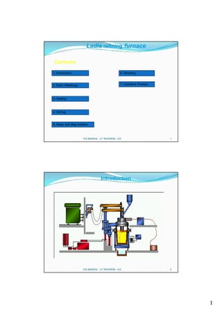
  • 2. Introduction The LF represents a reality in a large number of steel production lines since its origins date back to the era in which ladle furnace were equipped with slide gates and porous plugs. Thanks to the possibility of treating steel in the ladle, the melting furnace is no longer subject to long refining times and its production capacities have been accelerated while rendering time management much more flexible with respects to the CCM. In recent years all the above has contributed, thanks to a proper use of this machine, to a significant improvement, not only form a production point of view but also from a quality and economic point of view thus achieving interesting levels. CVS MAKINA - LF TRAINING - D.E. 3 Introduction Some theoretical indications with extensive operating description provided here below will show how this equipment, if use correctly, can provide a decisive support to three main points, namely: • Productivity • Quality • Cost reduction CVS MAKINA - LF TRAINING - D.E. 4 2
  • 3. Introduction The LF is designed to ensure the following main purpose: 1. Easier secondary metallurgy operations 2. Optimal and through homogenisation process 3. Accurate analyses for the CCM 4. Improved castability in the CCM 5. Achievement of cleaning steel 6. Reduction of the EAF consumption figures 7. Reduction of the EAF operating times 8. Increase in the productivity of the whole line EAF-LF-CCM CVS MAKINA - LF TRAINING - D.E. 5 Introduction 1. Easier secondary metallurgy operations The possibility of decreasing the S content level down to very values (ex.0.003%) is of basic importance. This would occur under ideal conditions. However the Key to a correct DeS process (normally reaching a delta ranging from 50% to 80%, between the S value during the tapping phase and the final S value of the CCM tundish) is the compliance with the three basic parameters, namely: • no slag is tapped from the EAF into the Ladle •the value of the free oxygen is lower than 30 ppm •during tapping and subsequently in the LF a slag is formed with a ratio higher than 2.1. Provided that the slag is properly prepared (basic and sufficiently fluid) the second positive effect is obtained. In fact, under this condition, many oxide and a large number of inclusion rise to the surface of the fluid slag thus leaving the steel very clean. CVS MAKINA - LF TRAINING - D.E. 6 3
  • 4. Introduction 2. Optimal and through Homogenisation Process Homogenisation is a very important process and it is achieved trough porous plugs, the number of which depends on the ladle size (one for ladle up to 80t, and two for larger ladles). The homogenisation guarantee the following: • High and regular speeds for chemical combinations • Elimination of temperature pick-up • Very representative samples for analysis • Acceleration of inclusion decantation • Required physical contact between steel and slag CVS MAKINA - LF TRAINING - D.E. 7 Introduction 3. Accurate Analyses for the CCM In order to obtain such result, it is recommended to observe very carefully the following conditions: •make sure the the stirring is correctly carried out at all times and that the adjusted of the argon and nitrogen flow rates and pressures are such that a steel ‘’bare eye’’ achieved with a diameter not exceeding 10-12 inches with respect to the slag •Always carry out the first analysis two minutes after beginning to heat the steel with electric arc when the slag is sufficiently liquid •When sampling the steel for the analysis (see above) check the level of free oxygen in the steel •Keep under control the operations by following the corresponding steel making standard report CVS MAKINA - LF TRAINING - D.E. 8 4
  • 5. Introduction 4. Improvement Castability in the CCM A considerable increase in the steel castability can be achieved provided that: • the tundish and nozzle are sufficiently hot, with the ladle having necessarily received the steel from the EAF at a standard temperature during tapping • the heating conditions are the same as those of the tundish without tapping slag from the furnace • all other basic requirements are complied with The above result can be achieved provided that: •the steel temperature is very constant time •the steel is much cleaner and free from macro inclusion •the steel is chemically free from considerable quantities of oxides CVS MAKINA - LF TRAINING - D.E. 9 Introduction 5. Achievement of cleaner Steel The simple fact that the treatment time, depending on the steel grade, lasts from a minimum of 25-30 min to a standard of 50-60 min, obviously leads to the decantation of impurities. This phenomena, that occurs due to the difference of specific weights, may be considerably accelerated, provided that the use is correctly, by varying the following factors: •temperature changes above 80°C as compared with the Tliq •calibrated stirring according to the current position, as to the specific operating procedure •use of correct slag viscosity CVS MAKINA - LF TRAINING - D.E. 10 5
  • 6. Introduction 6. Reduction of the EAF consumption figures 7. Reduction of the EAF operating times The decisive factor is that, by means of this system, the melting furnace is released from all the aspects relevant to the so-called refining process. As results,being just a melting machine, its functions will be the creation of a fixed matrix as far as analyses and temperature are concerned, without obviously pouring slag into the ladle. By saving time and being able to tap at relatively low temperatures, it follows that for the EAF there will be a considerable saving of : real time, power supply, electrode and refractory consumption Several times, by acting on the rate and on the repeatability, for long CCM sequences (from 5 up to 50) in progressive scale, the EAF performance can reach optimal levels thus reducing the relevant costs and improving performance levels to unexpected but actual results. CVS MAKINA - LF TRAINING - D.E. 11 Introduction 8. Increase in the Productivity of the whole Line (EAF-LF-CCM) Assuming to have a secondary metallurgy station it becomes easier to manage programs, times,rate and conditions by gradually optimising them and, in the vent of any delays of one of the production units, to use the LF as a buffer, which is able to cope with the problems caused by the CCM as well as EAF. Thanks to this natural flexible operation mode, sequence casting becomes easier with consequent increase in the productivity and reduction of the relevant costs. Another major factor, often considered as an effect, consists in the improvement of the quality level which, in the rolling process and in the other finishing phases, in addition to favouring high productivity levels, it considerable lowers the quantity of rejects. Substantially, this is a very strategic aspect that may easily result into positive returns as far as sponsoring is concerned but also as regards immediate economic profits. CVS MAKINA - LF TRAINING - D.E. 12 6
  • 7. Basic Metallurgy LIQUIDUS AND SOLIDUS TEMPERATURE. Pure Fe melts at 1536°C. If the liquid iron contains other elements ,it will no longer have a fixed melting point, but will rather melt within a solidification interval,determined by a solidus and liquidus temperature. The solidus temperature is of limited importance to us whereas the liquidus temperature is all the more important.. We use the T.liq as a reference level on top of which we add a certain over temperature for defining the optimum casting temperature. Fe is typically alloyed with Carbon, which changes the melting point from pure iron to a liquidus line. CVS MAKINA - LF TRAINING - D.E. 13 Basic Metallurgy CVS MAKINA - LF TRAINING - D.E. 14 7
  • 8. Basic Metallurgy Our method of calculation considers 1536.6°C as the solidification temperature of pure iron, because of the presence of alloyed and residual elements in the steel, which have the effect of decreasing the temperature, it is necessary to take into consideration the chemical composition of the steel in order to compute its liquidus temperature, Our logarithm, widely used for calculation, is based on statistically evaluated results of metallurgical laboratories. CVS MAKINA - LF TRAINING - D.E. 15 Basic Metallurgy Tliq = 1536,6 - (%C * Z) - (%E * W) Tliq = liquidus temperature C% Z E W 0.06-0.10 89 Si 8 %C = carbon content 0.11 -0.50 88 Mn 5 0.51-0.60 86 P 30 Z = multiplying factor for 0.61-0.70 84 S 25 carbon 0.71-0.80 83 Cr 1.5 0.81-0.90 82 Ni 4 %E = content of elements Cu 5 listed in the table Mo 2 V 2 W = multiplying factor for the Al 5.1 listed elements CVS MAKINA - LF TRAINING - D.E. 16 8
  • 9. Basic Metallurgy Spectrometer: nowadays ,this instrument is very fast in supplying the steel analysis for all the necessary and required elements, its principle is based on the basic assumption that each chemical element has its individual specter, with precise bands (similar to those found on a supermarket label) whilst the relevant percentage is determined in relation to the proportional light emissions. Within two minutes the sequences of the desired and required elements will be directly displayed on the video screen and is generally based on the following criteria… Standard order: C Mn Si P S Cu Ni Mo Sn Al As Ti V Nb W Ca B Co Te of course, the calibration and the reading curves, will be a function of the required analysis and of the usual percentages of certain elements. All this will be carried out through tests of samples with known chemical analysis to obtain the conversion factors. CVS MAKINA - LF TRAINING - D.E. 17 Basic Metallurgy Finally the L.F. Operator will obtain some figures that should be interpreted as follows. • 0.01% is equivalent to one centesimal point,therefore saying that c=18 is the same as c=0.18% or mn =67 is the same as saying mn =0.67% .This system is valid for the following elements c.Mn.Si.Cu.Ni.Cr. W. Mo. And co. • 0.001 is equivalent to one millesimal point ,therefore saying that p=29 is the same as saying p is 0.029,or al,=55 is the same as al=0.055.This system applies to the following characteristics:::;p.S.Al.Sn.As.Ti.Nb.B.V.Ca.Pb.Te etc…. • O2..N2 and H2 as already stated ,one ppm (i.e. one part per million) is equivalent to 0.0001% reference is made to carbon pick -up. CVS MAKINA - LF TRAINING - D.E. 18 9
  • 10. Basic metallurgy Secondary metallurgy is divided into two steps. • Operating steps • Techniques The basic steps are as follows 1. Preventing slag from leaving the primary melting units. 2. Mixing and homogenisation. 3. Heating. 4. Charging of additives. 5. Vacuum treatment.. 6. Shrouding of the steel flow in the ladle and Tundish. 7. Electromagnetic stirring during continuous casting. CVS MAKINA - LF TRAINING - D.E. 19 Secondary metallurgy CORRESPONDING TECHNIQUES. 1. Stirring gas treatment with porous plugs, lances or with the aid of electromagnetic stirring 2. Hopper fed alloying elements ,deoxidation agents or slag forming agents. 3. Lance injected solids 4. Vacuum degassing with the aid of various techniques 5. Spooling in of cored wire 6. Ladle furnace with electric arc The various methods and processes of secondary metallurgy are frequently combinable, giving rise to precisely defined sequences ,for the production of special steel grades and for the compliance within defined tolerances of the alloying elements or additions CVS MAKINA - LF TRAINING - D.E. 20 10
  • 11. Basic Metallurgy GENERAL CHARACTERISATION Slag is not an undesired by-product of refining. On the contrary, it is an indispensable prerequisite for it. The slag layer functions like a reservoir which can absorb and retain a tramp element like S, but also in case the process is not properly controlled, return the element to the bath and ruin the efforts of refining. Refining slags normally have CaO as the major constituent,and such slags are referred to as basic slags, in exceptional cases Acid slags with SiO2 as the main component are used , mainly for the removal of manganese from low manganese steels.. CVS MAKINA - LF TRAINING - D.E. 21 Basic Metallurgy BACKGROUND The reasons for preventing the primary furnace slag from entering the ladle furnace are : • minimizing the phosphorus reversion into the steel • minimizing the amount of oxygen entering the ladle. CVS MAKINA - LF TRAINING - D.E. 22 11
  • 12. Basic Metallurgy LIMITING THE LINING WEAR. The primary furnace slag contains more or less phosphorus pentoxide P2O5, bound to the lime as calcium phosphate. The P content depends on the raw material used in the primary furnace. Clean scrap and /or reduced pellets ( sponge iron made from pure ore ) give hardly any phosphorus in the steel (or in the slag) made in the arc furnace. The content of phosphorus pentoxide in the slag can vary from less than 1% to more than 20%. The acceptable amount of slag entering the ladle furnace is thus, amongst other things,dependent on the phosphorus level in the slag CVS MAKINA - LF TRAINING - D.E. 23 Basic Metallurgy The crude steel leaving the primary furnace is in general oxidized. The oxygen content being a function of the carbon level. Since there is a relationship between the the oxygen content in the steel and in the slag respectively, this means that the furnace slag can be more or less aggressive to the refractory lining . The oxygen exists in the slag as iron oxide Fe0, fluxes, MgO and CaO which are the main constituents of the refractory lining . The more of this slag coming into the ladle furnace, the greater is thus the risk of lining wear. This type of slag also has a negative effect on the yield of added alloys, especially those having a strong affinity for oxygen,such as Si, Al, Ti, etc. It is important in most cases to minimize the quantity of furnace slag entering the ladle furnace. CVS MAKINA - LF TRAINING - D.E. 24 12
  • 13. Basic Metallurgy On the other hand there are examples where large slag volumes are desirable in the ladle furnace, such as when desulphurising. This is in general fulfilled by adding adequate amounts of lime. If however, the P content in the primary furnace slag is sufficiently below the critical level, it is possible to let this slag ,or part of it ,remain in the ladle furnace to take part in the subsequent refining (Desulphurization) which will take place there. In practice the slag during primary melting , for instance in the arc furnace is allowed to run off during the final stages of the melting. At this stage the slag usually contains a high iron oxide content CVS MAKINA - LF TRAINING - D.E. 25 Basic Metallurgy After tapping into the ladle ,the steel is normally pre-deoxidized but it still contains a high oxygen content ,and the oxygen potential of the slag is very high,.In order to order to prevent the primary furnace slag from entering the ladle furnace there are three possible ways to deslag: 1. DESLAGGING OF THE PRIMARY FURNACE BEFORE TAPPING. 2. DESLAGGING OF THE LADLE BEFORE STARTING TREATMENT.. 3. RELADLING. The method used mostly today is,is to deslag before treatment,this can be done by tilting the ladle,.simply running off via a slag spout,or by the most popular method of using a slag rake CVS MAKINA - LF TRAINING - D.E. 26 13
  • 14. Basic Metallurgy Modern ladle cars ,have been fitted with a hydraulic system making it possible,to tilt part of the ladle car,and with the use of the slag rake make it very easy to deslag. A slag spout is necessary in order to protect the ladle flange and to prevent the build up of slag on the brim of the ladle. Which would jeopardize a satisfactory seal between the roofs and the ladle furnace.. The spout can be attached by a hydraulically operated device or placed on and removed from the ladle with the help of a crane. CVS MAKINA - LF TRAINING - D.E. 27 Basic Metallurgy CHEMICAL COMPOSITION. Refining slags are composed of the main constituents from the Ca0-SiO2- Al2O3 - MgO system. CaO comes from the added lime and the slag should normally be saturated with it. SiO2 and Al2O3 come from the primary furnace slag,deoxidation products and,to some extent from the refractory wear, Al2O3 is also an important flux in many synthetic slags. The MgO content normally comes from the dissolution of MgO in the ladle and roof refractories. CVS MAKINA - LF TRAINING - D.E. 28 14
  • 15. Basic Metallurgy MgO may be added as pure material or as dolomitic lime for reducing ladle lining wear,Its content is normally 6 to 8% in refining slags.. Addition of 5 to 10% of CaF2 may be needed for fluxing the slag. FeO, MnO and Cr2O3 appear, as “tramp” constituents and their presence is detrimental for the steel quality.Their sum should not exceed 1.0 to 1.5%. S appears as CaS and is picked up from the metal. P is practically absent in ladle refining slags,due to the low oxygen activity.. TiO2 may appear as a result of dissolution of bauxite refractories.It is also detrimental for steel quality. CVS MAKINA - LF TRAINING - D.E. 29 Basic Metallurgy Refining slags may have a different composition depending upon whether Si-killed,or Al -killed ( Si free) steels are being produced. Si -killed steels that shall be continuously cast into billets require that the slag,have a low Al2O3 ,content in order to avoid ,tundish nozzle clogging. Al -killed ,Si free steels require that the SiO2 content be low so as to minimize the Si pick-up from the slag by the metal CaO 56-62% CaO 56-62% SiO2 6-10% SiO2 15-20% Al2O 3 20-25% Al 2O3 5-8% FeO+MnO+Cr2O3 <2% FeO+MnO+Cr2O3 <2 MgO 6-8% MgO 6-8% S 0.3-2.0% S 0.3-1% CVS MAKINA - LF TRAINING - D.E. 30 15
  • 16. Basic Metallurgy CVS MAKINA - LF TRAINING - D.E. 31 Basic Metallurgy Slags for steel refining must have not only the right chemical character but also the right liquidus temperature, so that they are readily liquid but not overly aggressive at steelmaking temperatures. Slags have liquidus and solidus temperatures just like metals.In contrast to metals however, it is much more complicated to predict these temperatures as a function of the chemical composition, because there is a much stronger interaction between the slag constituents than between metal constituents. Even if a slag is liquid,it may have such a high viscosity,that further addition of flux is required.Generally speaking ,additions of Al2O3 or CaF2 are used to regulate the fluidity of slags on a rather empirical basis. CVS MAKINA - LF TRAINING - D.E. 32 16
  • 17. Basic Metallurgy HEAT CAPACITY The heat capacity for the aforementioned slags is 0.41kwh/(tonne,K) and practically independent of temperature within the 1500 - 1700 °C range. DENSITY The density of refining slags can be calculated with fair precision on the basis of empirical models.Densities for the two aforementioned slags are in the 2.7 to 2.8 kg/dm3 range for temperatures within the 1500 to 1700°C. CVS MAKINA - LF TRAINING - D.E. 33 Basic Metallurgy S te e l D e n sity A s F u n c tio n o f T e m p e ra tu re 0 .1 2 % C , 0 .2 5 % S i, 0 .7 5 % M n D en s ity, kg /d m 3 6 .9 5 6 .9 0 6 .8 5 1 ,5 5 0 1 ,6 0 0 1 ,6 5 0 1 ,7 0 0 T em p eratu re, C CVS MAKINA - LF TRAINING - D.E. 34 17
  • 18. Basic Metallurgy BASICITY The single most important numerical index which summarizes the composition of a slag and serves as a single parameter with which its chemical character can be correlated, is the (BASICITY INDEX.) Basicity is not a univocal notion at least 14 different definitions have been put forward over the years. The simplest and most widespread definition is the one by Herty in the 1920,s called V -RATIO and defined as : V-ratio =(WT-% Ca O ) / ( WT-% SiO2 ) The V-ratio ignores the effects of the other basic (FeO,MnO, MgO, 0 and acid ( Fe2O3,Al2O3,P2O5) OXIDES.More complex definitions abound but do not add any further substance to the discussion that follows.We shall therefore limit ourselves to the use of V ratio for basicity. CVS MAKINA - LF TRAINING - D.E. 35 Basic Metallurgy The V ratio cannot be successfully used for accurately predicting desulphurisation capacity but is merely and expedient way of roughly characterizing a slag as regards its refining capacity The V ratio in refining slags lies normally in the 1.8 to 3.5 range. CVS MAKINA - LF TRAINING - D.E. 36 18
  • 19. Basic Metallurgy SULPHIDE CAPACITY One of the most important tasks of refining slag is to absorb and hold S as sulphide. S Slag property to hold S is called Sulphide Capacity and it is defined as Cs = Ks * (%S) * [aO ] / (fS * [%S ] where log Ks = (935/T - 1.375) Cs can be calculated from (%S) content in the slag, oxygen activity [aO ] in the steel, sulphur concentration [%S ] in the steel, activity coefficient fS and the temperature. The expression for sulphide capacity can be witten as the following form that is called sulphur partition ratio Ls Ls = (S%)/[S% ] = Cs * fs / (Ks * aO) and looking the above formula we understand the factors that promote the desulphurisation. CVS MAKINA - LF TRAINING - D.E. 37 Basic Metallurgy Interaction of Carbon on Sulphur Activity Coefficient f S As Function of C Content at 0.03 % S, 1600°C Activ ity Coefficient fS 5 4 3 2 1 0 0 1 2 3 4 5 C Content, % CVS MAKINA - LF TRAINING - D.E. 38 19
  • 20. Basic Metallurgy REFINING REACTIONS. Refining of steel normally means the removal of one or several elements from the metal bath.Such refining is brought about by slag metal reactions,gas-metal reactions or metal bulk reactions. Refining of the following elements will be discussed: S,H,N,C,O. In addition fundamental aspects of calcium treatment will be discussed. Refining of a particular element may be performed by one or several of the above mentioned reactions.Desulphurisation is a typical slag -metal reaction whereas deoxidation can be carried out as a metal bulk reaction,slag -metal reaction ,or even a gas -metal reaction. CVS MAKINA - LF TRAINING - D.E. 39 Basic metallurgy Removal of S from steel into the slag is conventionally illustrate by the reaction [S] + CaO CaS + [O] To achieve a good desulphurisation it is first of all necessary that three fundamental conditions be satisfied. 1. Basic Slag. 2. High Temperature (60-80deg greater than delta T sl). 3. De -oxidation of the bath(aO2 less than 40ppm). The stirring of the bath and the reactivity of the slag are important to speed up the formation of Ca Sulphide. CVS MAKINA - LF TRAINING - D.E. 40 20
  • 21. Basic metallurgy Desulphurisation is mathematically represented by the formula S final = S initial * e -ks *(A/V)* t A = bath area m 2 V = metal volume m 3 Ks = desulphurisation rate constant m/min t = process time Ks values depending on the stirring power and we can consider : Ks in the LF = 0.08 (0.8-1.2 Nl/ton min) Ks in the VD = 0.20 More details Next lesson CVS MAKINA - LF TRAINING - D.E. 41 Basic metallurgy Desulphurisation Several elements that occur as tramp elements or alloying elements in the metal bath can move between slag and metal. From a ladle refining point of view, the most important element in this respect is S, and refining of it will therefore be described in rather detail. The partition of an element between slag and metal is controlled by the chemical environment, principally oxygen activity and slag basicity, and can be predicted by use of thermodynamic calculation models. CVS MAKINA - LF TRAINING - D.E. 42 21
  • 22. Basic metallurgy Removal of S from a metal bath into the slag is conventionally illustrated by the reaction: S + CaO CaS + O A basic slag is considered be completely ionised so that we preferably write the desulphurising reaction: S + O2- S2- + O By writing in this manner, we also confirm the fact that not only CaO but also MgO, FeO, Na2O and other oxides to a varying degree contribute the oxygen ions necessary for the reaction. We have already defined an expression for the S partition between slag and metal (see section on sulphide capacity). Now we want to predict the final sulphur content in the metal, however, for which purpose we must know the specific slag weight, i e kgs of slag per ton of metal, slag sulphide capacity, the initial concentration of S in the slagbuilders and in the metal and, finally, the S activity coefficient in the metal. We assume that the total amount of S remains constant, i e that what has left the metal will be found in the slag. CVS MAKINA - LF TRAINING - D.E. 43 Basic metallurgy It is then possible to derive the expression: [ %S ]*W ( ) + %S0 *W slag [ %S ]= final 0 steel W steel +LS *Wslag where ‘W’ denotes weight. At this point, we substitute L S for C S * fS / (K S * a O) as described earlier in the discussion about Sulphide Capacity. That brings us to the expression for final, equilibrium S content in the metal : %S0 *W steel %S0 *W slag %Sfinal W steel CS* fS / KS* a O *W slag The activity aO can easily be calculated or measured in metals of very varying composition; fS is likewise easily calculated using Wagner’s formalism; C S can be calculated from slag analysis and temperature. Weights of metal and slag are already known. We therefore have all necessary information for calculating the maximum possible extent of desulphurisation. The figure shows an example with equilibrium sulphur content in the metal as function of slag V-ratio. CVS MAKINA - LF TRAINING - D.E. 44 22
  • 23. Basic metallurgy It is evident that the V-ratio must be at least greater than 2 in order that a good desulphurisation be attained. Referring back to the phase diagram CaO - SiO2 - MgO - Al2O3, the best desulphurisation results are attained with slags which are just saturated with CaO. The fact that a considerable desulphurisation is possible does not necessarily mean that a low final S content will actually be reached. The exchange reaction between metal and slag takes time and is mainly influenced by the stirring and mixing intensity. Desulphurisation is mathematically represented by the well-known exponential function CVS MAKINA - LF TRAINING - D.E. 45 Basic metallurgy kS * A / V * t %S % S0 %S * e %S where %S = S content at time ‘t’ %S0 = initial S content in metal %S = S content after infinite time (equilibrium content) kS = desulphurisation rate constant, m/min A = stagnant metal-slag interfacial area, m 2 V = metal volume, m 3 t = desulphurisation time, min. In the above function, we know everything except for the rate constant kS . The rate constant can be approximated from the gas stirring flowrate, temperature and ambient pressure but such models are not accurate. Measurement is actually the best method of determining the rate constant for various operational cases such as heating in ladle furnace and treatment under vacuum. CVS MAKINA - LF TRAINING - D.E. 46 23
  • 24. Basic metallurgy R a te o f D e s u lp h u ris a t io n in L F a n d V D a t In itia l S 0 .0 3 0 % , E q u ilib riu m S 0 .0 0 8 % S C o n te n t, % 0 .0 3 5 LF VD E q u il i b ri u m 0 .0 3 0 k S 0 .0 5 k S 0 .2 0 0 .0 0 8 % 0 .0 2 5 0 .0 2 0 0 .0 1 5 0 .0 1 0 0 .0 0 5 0 10 20 30 40 50 60 70 D e s u lp h u r is a tio n T im e , m in CVS MAKINA - LF TRAINING - D.E. 47 Basic metallurgy Evaporation of Metallic Constituents Metallic constituents of a steel bath have vapour pressures that can relatively easy be calculated as described previously. If we let gas bubbles pass through the melt, they will therefore pick up evaporated constituents, theoretically up to the saturation point at which the partial pressure reaches equilibrium with the activity of the element in the liquid metal. Kinetic constraints may prevent the bubbles from becoming saturated as they rise, however. The metallic vapours condense and, generally, oxidise above the metal bath to form what we simply experience as dust. CVS MAKINA - LF TRAINING - D.E. 48 24
  • 25. Basic metallurgy Vacuum treatment and electric arc heating are two well-known cases of generous evaporation and dust formation, although for different reasons. Vacuum treatment generates substantial quantities of dust mainly because the inert gas bubbles passing through the metal expand strongly due to the low pressure above the metal bath and therefore pick up much evaporated solutes. Electric arc heating generates much dust, principally because the temperature of the electric arcs is extremely high which induces a lot of evaporation. Zinc and lead have very high vapour pressure at steelmaking temperature and may therefore be found in large quantities in dust. Such dust must be disposed of under safe conditions so as not to contaminate environment. Manganese has got a comparatively high vapour pressure. Elevated levels of MnO are therefore always found in dust from secondary metallurgy installations. Vacuum treatment may produce a lot of pyrophoric, condensed Mn particles in the suction line. CVS MAKINA - LF TRAINING - D.E. 49 Basic metallurgy Examination of dust from ABS in the VD dust separator E v a p o r a tio n o f M e ta ls Element Content, wt-% a n d D u s t G e n e r a tio n Fe 4-6 O2 Mn 10-15 D ust Cr 0-0.3 Ni 0-0.1 Cd 0-0.003 Cu 0.5-0.7 pFe Zn 15-30 Fe Pb 2-6 CaO 10-12 T Mn pM n SiO2 1-5 Al2O3 0.2-3 pCr Cr MgO 15-35 S tirr in g G a s CVS MAKINA - LF TRAINING - D.E. 50 25
  • 26. Basic metallurgy C alc ulated E v aporation of Elem ents as F unction of P ressure During Vacuum D egassing 1600 C , 1 % M n, 0.05 % A l, 25 m in utes Ev aporated A m ount, kg/ton 0 .1 0 Mn kg/ton ne 0 .0 8 Fe kg/ton ne 0 .0 6 Al kg/ton ne 0 .0 4 T o tal kg/ton ne 0 .0 2 0 0 1 2 3 4 5 6 7 8 9 10 P res s ure, torr CVS MAKINA - LF TRAINING - D.E. 51 Basic metallurgy FLUSHING OF DISSOLVED GASES BY GAS PURGING The fact that the partial pressure of a dissolved gas depends upon its activity in the metal, and hence upon its concentration, can be taken of for flushing a dissolved gas out of the metal. When the metal bath is flushed by an inert gas , for example Argon, the atoms of the dissolved gas(-es) will recombine at the inert gas bubble surface and escape into the bubbles.There, the dissolved gas builds up a partial pressure which approaches equilibrium with the activity of the dissolved solute. Taking nitrogen for example 2[N ] 2N N2 CVS MAKINA - LF TRAINING - D.E. 52 26
  • 27. Basic metallurgy The volumes of purging gas and dissolved gas in a bubble are proportional to their respective partial pressures so that Vdiss/Vpurge =Pdiss/ Ppurge furthermore ,the total pressure is equal to the sum of the partial pressures of dissolved gas(es) and purging gas according to P=Pdiss +Ppurge Flushing of Dissolved Gases by G as Purging Layer Of S urfactant 2N p N2 T 2H p H2 Stirring Gas CVS MAKINA - LF TRAINING - D.E. 53 Basic metallurgy DEOXIDATION. Deoxidation is the process by which the content of dissolved oxygen is reduced in the metal.One distinguishes between three different techniques for bringing about deoxidation 1. PRECIPITATION DEOXIDATION 2. TOP SLAG DEOXIDATION. 3. VACUUM CARBON DEOXIDATION. CVS MAKINA - LF TRAINING - D.E. 54 27
  • 28. Basic metallurgy PRECIPITATION DEOXIDATION - REMOVAL OF SLAG INCLUSIONS. Precipitation deoxidation is by far the most common deoxidation method. As the name suggests,a deoxidiser normally AL or Si is added to the metal bath. Upon addition and mixing, the dissolved oxygen will react with the added d.the combination of oxidizer so as to produce oxides which precipitate in the melt. The precipitation deoxidation in itself does not reduce the oxygen content but just transforms the dissolved oxygen into oxidic oxygen. Next ,the oxidic oxygen particles must be removed from the metal bath by flotation. Expressed in the simplest way,the respective reactions are, Al+O2 Al2O3 and Si+ O2 SiO2 CVS MAKINA - LF TRAINING - D.E. 55 Basic metallurgy The dissolved oxygen content which results from precipitation deoxidation depends upon the value of the equilibrium constant and upon the activities of the reactants and the reaction products. The dissolved oxygen content, is what really concerns us for the sake of cleanness of the metal. Al2O3 appears as clusters of small, solid, sharp- edged particles in the metal. They are easily floated by gas stirring and induction stirring, Si is rarely used as a single deoxidiser but rather in combination with manganese. CVS MAKINA - LF TRAINING - D.E. 56 28
  • 29. Basic metallurgy The combination of Si and Mn more efficiently reduces the oxygen content than either one of the elements alone. The reason is as follows, when using only silicon as a deoxidiser, the deoxidisation product is pure SiO2 the activity which is equal to unity. This SiO2, is solid up to 1713°C. Furthermore the precipitated particles do not stick together like Al2O3 particles but appear as discrete particles in the metal.They are therefore not easy to flotate after precipitation. When adding both Si and Mn to the metal bath,both elements will be engaged in the deoxidation so that the reactions will run in parallel. Si +2O >>>>>SiO2 Mn + O >>>>>MnO CVS MAKINA - LF TRAINING - D.E. 57 Basic metallurgy The reaction products SiO2 and MnO attract one another strongly because SiO2 is of acid character whereas MnO is of strongly basic.A manganese silicate will therefore form, in which the activities of SiO2 and MnO are strongly reduced. D is s o lv e d O x y g e n C o n te n t in S i( -M n )- k ille d S t e e l a t 1 6 0 0 ° C C 0 .1 2 , M n /S i= 3 . 0 Oxygen, ppm 200 150 100 S i o n ly 50 S i- M n 0 0 0.05 0 .1 0 .1 5 0.2 0.25 0 .3 S i C o n te n t, % CVS MAKINA - LF TRAINING - D.E. 58 29
  • 30. Basic metallurgy One normally aims at an Mn/Si ratio after deoxidation of >3. This ensures that the manganese formed silicate is liquid at steelmaking temperatures. Precipitation deoxidation generates slag inclusions ( in most cases AL2O3 or Mn -silicates) that must be removed by flotation from the metal bath. The picture illustrates schematically how a high, initial dissolved oxygen content drops much faster than the total oxygen content. The difference between total oxygen content and dissolved oxygen content is the oxidic oxygen tied to the deoxidizer in the precipitates. CVS MAKINA - LF TRAINING - D.E. 59 Basic metallurgy Precipitation Deoxidation Floatation of Inclusions Addition of Deoxidiser at Time = 0 Oxygen, ppm 80 60 40 Oxide + Dissolved Oxygen Oxide Oxygen 20 Dissolved Oxygen 0 0 5 10 15 20 25 30 Time, min CVS MAKINA - LF TRAINING - D.E. 60 30
  • 31. Basic metallurgy .The metal bath is always exposed to reoxidation,which generates new precipitates. Such reoxidation is caused by FeO, MnO and Cr2O3 in the top slag refractories. It is also caused by direct oxidation with atmospheric oxygen coming into the metal bath via an open purging eye or via the teeming stream. CVS MAKINA - LF TRAINING - D.E. 61 Basic metallurgy Deoxidation and Reoxidation Mechanisms Al O2 FeO O O Cr2O3 O 2Al+3O =>Al2O3 Stirring Gas CVS MAKINA - LF TRAINING - D.E. 62 31
  • 32. Basic metallurgy CALCIUM TREATED STEELS The aim of calcium treatment is in most cases to improve castability, by modifying the sharp edged, solid Al2O3 particles into spherical liquid calcium aluminates. If reoxidation is allowed to take place after calcium treatment, new unmodified Al2O3 particles will be generated and they will again obstruct the casting. Precisely for this reason, Ca treatment must ,with few exceptions, be the very last ladle refining operation, after which the steel must be cast without delay. The stirring power and stirring type are of decisive importance for the final cleanliness of the steel. CVS MAKINA - LF TRAINING - D.E. 63 Basic metallurgy Refining by calcium treatment means that the metal bath is treated with metallic calcium. This treatment is done to improve the castability and /or improve the mechanical properties like isotropy with the steel product. Several forms of calcium can be used, for example SiCa ,Ca pellets,and CaFe. Whatever the form of Ca used it will immediately vaporize in contact with the steel, because the vapour pressure of pure Ca is 1.92atm at 1600deg. Its solubility at 1600 °C and 1atm is only 300 ppm. Castability is improved by the reaction between Ca and Al2O3 particles in the steel according to: 3Ca + Al2O3 >>>>>> 3CaO +2Al. CVS MAKINA - LF TRAINING - D.E. 64 32
  • 33. A l 2 O 3 -C a O CVS MAKINA - LF TRAINING - D.E. 65 Basic metallurgy Al2O3 particles are solid and sharp edged at steelmaking temperatures. They are prone to accumulating in the tundish nozzles and obstructing the steel flow. By reaction with the formed CaO, the the Al2O3 particles will form liquid spherical Ca -aluminate particles which flow through the nozzles without obstructing them. x CaO + yAl2O3 >>>>>>>>>>(CaO)x (Al2O3)y. Since Ca has such a strong affinity to oxygen and sulphur it can if supplied in sufficient quantity,react and transform all oxides and sulphides existing in the metal bath..Sulphides will be transformed to CaS whereas other oxides will be transformed to CaO and release Mn ,Si etc back to the metal. CVS MAKINA - LF TRAINING - D.E. 66 33
  • 34. Basic metallurgy Modification of Non-Metallic Inclusions by Ca Treatment Before Ca Treatment After Ca Treatment sulphides MnS CaS alumina Al2 O 3 Al2 O CaO silico aluminates Al2 O 3 +MnO Calcic +SiO 2 globular inclusion CVS MAKINA - LF TRAINING - D.E. 67 Basic metallurgy C h a n g e s in In c lu s io n C o m p o s itio n D u rin g In je ctio n o f C a a t 1 6 0 0 °C S teel: 0.1 C,0 .2 S i,0 .4 5 M n , 0 .0 3 A l, 0 .0 2 S % A l2 O 3 in A lum inates, % C aS in In clus ions 100 1 60 0 °C L iq u idu s 80 A lu m ina in c alc ium a lu m ina tes , % 60 40 C aS in in clu s ion s La titu d e 20 inc lu sio ns fully liqu id 0 0 20 40 60 80 100 Injec ted C a Q uantity, A rbitrary U nits CVS MAKINA - LF TRAINING - D.E. 68 34
  • 35. Basic metallurgy The amount of Ca injected into the steel shall be such that the composition of the Ca -alluminate falls roughly within the 3(CaO)(AL2O3) to (CaO)(AL2O3) range. This ensures that the formed aluminates are liquid at steelmaking temperature. Too little Ca causes insufficient modification and solid inclusions. Too much Ca generates solid inclusions as well. As the inclusions become increasingly rich in CaO a point is reached at which Ca starts reacting with the S to create CaS according to Ca + S>>>CaS. This CaS is solid and will obstruct casting nozzles just like Al2O3 particles. It is therefore important that the S content be reduced by another method of desulphurization before Ca treatment in order that CaS will not be formed by direct reaction with Ca. CVS MAKINA - LF TRAINING - D.E. 69 Basic metallurgy As a rule of thumb, the S content should be below 0.010 % before Ca treatment. The consumption of Ca for modification of slag inclusions is 0.15.to 0.35 kg.ton (expressed as pure calcium). Due to its high vapour pressure and its very limited solubility in steel, practically all Ca in the steel after Ca treatment appears as oxide or sulphide. No significant amount of dissolved Ca remains as a buffer for modifying any AL that may be deoxidized after complete Ca treatment. CVS MAKINA - LF TRAINING - D.E. 70 35
  • 36. Basic metallurgy If the steel for one reason or another has become deoxidized after Ca treatment , it will have to be Ca treated again . Pneumatic injection of Ca ensures that all Ca reaches to the bottom layer of steel in the ladle. In case wire feeding is employed for Ca feeding, the wire diameter and injecting velocity must be selected so as to ensure that the wire rests the bottom of the ladle before melting and releasing this Ca vapours. Ca supply rate should not exceed about 80gr/tonne,min in order that the bath agitation be contained . CVS MAKINA - LF TRAINING - D.E. 71 Basic metallurgy C a S i W i r e F e e d r a te a s F u n c t io n o f S t e e l W e ig h t f o r 1 2 m m W ir e D i a m e te r F e e d r a t e , m / m in 260 240 220 200 O d e r m a th D ia 1 2 m m 180 160 140 120 0 50 100 150 200 250 S t e e l W e ig h t , to n CVS MAKINA - LF TRAINING - D.E. 72 36
  • 37. Heating The electric arc burns between electrode and metal bath at a tempe rature of 4000 - 8000°C. At this high tem perature the gas in the arc become s ionised and transform s into a plasm a. The high plasma temperature promotes an efficient energy transfer between arc and bath under each electrode. The electrom agnetic fields in each phase G eneration of Hot-Spot W ear exe rt a strong influence on the arcs so that A rc D eflection - Hot Particle Jet they deflect from vertical orientation and incline towards the ladle wall during ea ch half cycle. The higher the electrode current and the closer the grouping of the electrodes, the stronge r the deflection . Electrodynamics forces cause the plasma to have a very high internal pressure. The arc therefore exerts a pressure on the m etal bath and creates a dimple. The electrodynamics force s in the electric arcs generate a gas stream with a ve locity of about 1500 m/s along the arc. The velocity is particularly high during the half cycle when the electrode has negative polarity. CVS MAKINA - LF TRAINING - D.E. 73 Heating The electric arc length is approximately L arc = Varc (Volt) - 35 (mm) 35 = anode -cathode voltage drop(constant), used for accelerating and decelerating electron and ions. E le c t r ic A r c L e n g t h a s F u n c t io n o f A r c V o lt a g e A rc L eng th, m m G a s S ti r r in g 100 80 60 40 20 In d u c t i ve S ti r r i n g 0 40 60 80 100 12 0 140 A r c V o lt a g e , V CVS MAKINA - LF TRAINING - D.E. 74 37
  • 38. Heating Power input into a ladle furnace is normally limited by the refractory wear rate. The actual refractory wear rate is a very complex function of,among other factors the following : Arc power input Arc Power Input Limitation Transmission of Heat to Metal Bath Refractory type and quality Metal and slag temperature. Bath Height,m Thermal profile in the refractory lining. Arc Power Slag-Metal 2.0 MW/m Metal and slag composition. Interface Level Slag thickness. Type and power of stirring Ladle furnace geometry. Temperature, °C CVS MAKINA - LF TRAINING - D.E. 75 Heating The electric arcs are immersed in a slag which absorbs a large part of the heat and transfers it to the metal bath.The slag is superheated 50--150k in relation to the metal temperature. The metal bath actually cools the slag. The metal bath must be stirred by gas or inductive stirring so that the transferred heat becomes homogeneously distributed. A practical and reasonable approach to dimensioning the electric power supply is to make it proportional to the heat transferring area.=Bath area CVS MAKINA - LF TRAINING - D.E. 76 38
  • 39. Heating Experience shows that an arc power input of up to about 2mw/2 bath area can be transferred to the metal bath and is tolerable as a dimensioning criterion for the power supply. The arc power is not measured but can be calculated. As a typical value,the arc power is about 84 - 88% of the active power being supplied by the transformer. The remaining 12% are lost in resistive heating of the electrical conductors and the electrodes. The heating rate as a function of the active power (ie.[Arc power]/0.88) is shown . CVS MAKINA - LF TRAINING - D.E. 77 Heating LF H eating Rate vs. Specific Power Input 9 H eating R ate, K/m in 8 7 6 W ate rc. roof 5 °C/m in Refr. roof 4 °C/m in 3 2 1 0 0 0.05 0 .1 0.15 0.2 0 .2 5 Ac tive Power, MW /tonne Experience shows that an arc power input of up to about 2 MW/m2 bath area can be transferred to the metal bath and is tolerable as dimensioning criterion for the power supply. CVS MAKINA - LF TRAINING - D.E. 78 39
  • 40. Heating The following operational aspects of arc heating will be discussed 1. Slag composition and thickness 2. Stirring of metal 3. Carbon pick -up 4. Electrode wear 5. Pick up of gases from the atmosphere 6. Refractory wear CVS MAKINA - LF TRAINING - D.E. 79 Heating The electric arc is a plasma ,the stability of which depends upon the presence of a conductive and insulating slag layer. High arc stability is essential for attaining,high average power input and this is one of the many reasons why a slag layer must always be present during arc heating.. Metallurgical refining slag are in most cases of basic character i.e. %CaO / %SiO2 > 2 Such slag have sufficient electrical conductivity. The more acid slag ,the more pronounced the the tendency of the electrodes to jump up and down. CVS MAKINA - LF TRAINING - D.E. 80 40
  • 41. Heating If the slag layer becomes excessively thick,say 150 to 200mm ,the slag layer may become superheated 1800 to 1900 °C ,and heating of the metal bath virtually cease despite continuous power supply. In such a case CaO in the slag will react with the graphite in the electrodes to form calcium carbide according to the strong endothermic reaction CaO+3C+q>>>>>CaC2 +CO.The carbide dissolves on the slag ,and may later react with the humidity according to, CaC2+H2O>>>>>>C2H2+CaO.To form acetylene,which is explosive.Care should be taken that the slag thickness is properly controlled so as to avoid carbide formation .. CVS MAKINA - LF TRAINING - D.E. 81 Heating The metal bath picks up carbon from the electrodes. The extent of this carbon pick-up depends on the following factors,. • Oxygen activity in the metal bath. • Metal bath stirring method. • Arc length. Experience shows that carbon pick-up by a rimming steel,(oxygen activity >150ppm) is practically negligible because carbon from the electrodes reacts with dissolved oxygen in the metal bath to form CO. The situation is different in steels with lower oxygen activity. CVS MAKINA - LF TRAINING - D.E. 82 41
  • 42. Heating Absorbed by the metal.The electrode tip wear is visible as a cavity in the electrode at the electric arc foot-point. Fluctuations are provoked by stirring of the metal bath. Gas stirring provokes a rather unsteady surface whereas inductive stirring ,if installed provokes a standing w aeve of rather constant profile. The incidence of metal droplets coming into contact with the electrodes is greater with gas stirring than with inductive stirring and the carbon pick- up is higher.The arc length is obviously of decisive importance for the carbon pick-up.A study on carbon pick -up as a function of arc length shows that the arc length for gas stirred ladle furnaces must be about 6.5cm in order that carbon pick-up will not exceed 2.0.To 2.5 ppm min.The corresponding figure for inductive stirred ladles is rather 5.0 cm. CVS MAKINA - LF TRAINING - D.E. 83 Heating C pick-up during heating (ppm /m in) 30 20 C-pick-up gas stiring C-pick-up 10 Ind. stir 0 0 20 40 60 80 100 Arc leng th [m m ] CVS MAKINA - LF TRAINING - D.E. 84 42
  • 43. Heating Electrode wear is generally described as a combination of tip wear and side wear. The electrode wear is roughly proportional to the energy consumption in the ladle furnace. The total wear,expressed as kg of graphite per tonne of steel,can be estimated, to 0.8 to 1.2% of the energy consumption,expressed as kwh/tonne, thus corresponds to a graphite consumption of 0.48 to 0.72 kg/tonne. CVS MAKINA - LF TRAINING - D.E. 85 Heating SIGRI Nominal diameter Lenght Weight per electrode Nipples-Kg and dimension AxL 1500 312 Kg 15 215.90-304.80 400 1800 376 Kg 20,5 241.30-338.60 2100 445 Kg UCAR Nominal diameter Lenght Weight per electrode Nipples-Kg and dimension AxL 1500 324 Kg 222 T4 15,9 222.25X304.80 400 1800 397 Kg 222T4L 17,9 222.25X355.60 2100 456 Kg * weight wthout nipple Ucar AGX 250-450 diameter mm bulk density 1.65-1.72 t/m3 kg/dm3 g/cm3 specific resistance 4.8-6.0 microohm * m flexural strenght 9.0-12.5 Mpa tensile strenght 6.0-8.5 MPa coefficient ot thermal expansion WG 0.5-1.0 microm/°Cm(30-100 °C) porosity 20-24 % thermal conductivity 210-280 W/m °C real density - all fully graphitized material have a real density of about 2.20 to 2.25 CVS MAKINA - LF TRAINING - D.E. 86 43
  • 44. Heating Provide premium grade electrodes are being used, electrode consumption is mainly dependent on steelmaking process conditions. Current level, power on time, oxidizing electrode surface area and tons per hour are the most important parameters influecing electrode consumption. Empiriacally developed formula are avalilable to calculate the amount of the two continuous electrode consumption process. Typical average oxidation and sublimitation rates are : 2 RsubAC = 0.0135 kg/kA hr - per one electrode tip Rox = 8 Kg/m2 hr - for the oxidinziing cone of water spray cooled electrodes. Calculation of continuous graphite consumption (sublimation) I = current per phase (KA) 2 tpo = power on (hrs) C tip = Rsub * ( I * tpo) / ( 0.454 * P ) [Kg/ton] P = productivity (tons/heat) Calculation of continuous graphite consumption (oxidation) A = oxidizingelectrode surface area (m2) ttap = tap to tap (hrs) side = Rox * ( A * ttap) / P [Kg/ton] P = productivity (tons/heat) CVS MAKINA - LF TRAINING - D.E. 87 Heating Specific electrodes consumption performed at Alpha Steel Guaranteed values Guarante electrode consumption 0.012 Kg/kWh Electrode consumption obtained 0.007 Kg/kWh Initial weight (Kg) Final weight (Kg) delta W (Kg) Electrode column 1 908 760 148 Electrode column 2 908 796 112 Electrode column 3 908 780 128 Total weight 1-2-3 2724 2336 388 Total Electric consumption after 18th heats 56800 Kwh S.E.C obtained after 18th heats 0,007 kg/kWh Initial weight (Kg) Final weight (Kg) delta W (Kg) Electrode column 1 908 698 210 Electrode column 2 908 740 168 Electrode column 3 908 735 173 Total weight 1-2-3 2724 2173 551 Total Electric consumption after 28th heats 80700 Kwh S.E.C obtained after 28th heats 0,007 kg/kWh Initial weight (Kg) Final weight (Kg) delta W (Kg) Electrode column 1 908 601 307 Electrode column 2 908 647 261 Electrode column 3 908 641 267 Total weight 1-2-3 2724 1889 835 Total Electric consumption after 39th heats 113800 Kwh S.E.C obtained after 39th heats 0,007 kg/kWh CVS MAKINA - LF TRAINING - D.E. 88 44
  • 45. Heating There are numerous factors which affect the final nitrogen level • scrap •DRI usage •long arc versus short arc •tap carbon •foaming slag practice •bottom stirring •tapping •deoxidation practice •ferro alloys CVS MAKINA - LF TRAINING - D.E. 89 Heating Electric arc heating is potentially cause a substansial pick-up of atmospheric gases, notably nitrogen N2 2N 2 [N] The arc caused the N2 molecule to dissociate to atomic N or ions. Nitrogen removal is also affected by surface actives elements O and S. CVS MAKINA - LF TRAINING - D.E. 90 45
  • 46. Heating P ic k - u p o f N it r o g e n a s F u n c t io n o f S la g T h ic k n e s s N it r o g e n P i c k - u p , p p m 40 30 20 10 0 0 20 40 60 80 100 120 140 160 180 200 S la g T h ic k n es s , m m KSC CVS MAKINA - LF TRAINING - D.E. 91 Heating Pick-up o f Hy dro ge n in LF after V ac uu m D ega ssing as Fun ction o f He ating T im e H ydro ge n C o nte nt, p pm 2 1.8 1.6 1.4 1.2 1 0.8 0 20 40 60 80 H ea tin g Tim e, m in s H ea t W e ig ht 17 2 tonn es CVS MAKINA - LF TRAINING - D.E. 92 46
  • 47. Heating The refractory wear rate in the ladle,can be characterised as being of two kinds: • General slag line wear It is caused by the gradual dissolution of the slag line, refractory, mainly MgO in the slag. • Hot-spot wear The extent of this wear mainly depends on • slag composition • working temperature • poor stirring • electrode regulation CVS MAKINA - LF TRAINING - D.E. 93 Heating M g O S o lu b ilit y a s F u n c t io n o f S la g B a s ic ity a t 1 5 % A l2 O 3 a n d 1 6 0 0 ° C M gO C o n te n t i n S la g , % 20 18 16 14 12 10 8 6 4 2 0 1 2 3 4 5 6 7 8 S l a g B a s i c i t y , % C a O / % S iO 2 CVS MAKINA - LF TRAINING - D.E. 94 47
  • 48. Heating Where does the electric energy go ? • Heating of the steel Utilisation of Electric Energy, kWh/tonne • Fusing of the slag builders. 100 ton LF, Steelgrade 20CrNi4 8.4 Melting Alloys 9.2 • Heating of the slag. Fusing Slagbuilders Metal Heating 18.2 • Melting of the alloys. • Resistive losses in power Slag Heating0.5 supply systems and electrodes. • Losses to refractory, Resisitive Losses 16.8 42.4 Refract., Ambient roof, off gas and ambient. The pie chart shows an example of electric energy distribution including vacuum treatment CVS MAKINA - LF TRAINING - D.E. 95 Heating Selection of operating point for the ladle furnace. The ladle furnace operator can set independent variables only, which define the so called operating point of a ladle furnace.. 1. Secondary voltage. 2. Electrode current. The choice of operating point will then decide what values will be obtained of the independent variables active, and reactive power, power factor heating rate ... CVS MAKINA - LF TRAINING - D.E. 96 48
  • 49. Heating We shall here discuss how suitable operating pints are selected for a given ladle furnace,the parameters which must be optimised are: • Electrode current • Active and apparent power • Arc power • Power factor • Arc length. CVS MAKINA - LF TRAINING - D.E. 97 Heating Ex am ple O perating P oints for Ladle Furnace Power, A rc Power, MW , Reac t. P ower, MV Ar, Power F actor Arc Length, cm 14 1 .4 12 1 .2 10 1 8 0 .8 6 0 .6 4 0 .4 2 0 .2 0 0 0 10 20 30 40 E lectrode Current, kA A ctive P ow er A rc P owe r Reac tiv e Po we r Arc Leng th Po we r Fa ctor MW MW M VA r cm CVS MAKINA - LF TRAINING - D.E. 98 49
  • 50. Heating Electrode current. Graphite electrodes can accept a certain maximum current density without being damaged. Higher current density may provoke cracking phenomena and superheating of the electrode joints. The maximum current densities recommend by the suppliers take into account that a reduction of the electrode section takes place due to side oxidation during use. CVS MAKINA - LF TRAINING - D.E. 99 Heating M A X IM U M E L E C T R O D E C U R R E N T F O R V A R IO U S E L E C T R O D E G R A D E S M a x im u m c u rre n t, k A 70 60 50 40 30 20 10 250 300 350 400 450 500 550 600 E le c t ro d e D ia m e te r, m m S ta n d a r d Im p re g n a te d CVS MAKINA - LF TRAINING - D.E. 100 50
  • 51. Heating Active and apparent power The maximum active power is limited by the maximum permissible arc power. Higher power will lead to rapid destruction of the refractory lining in the ladle. Even though the maximum power with respect to tolerable refractory wear rate is not exceeded. One must also check that the transformer itself is not loaded too much. CVS MAKINA - LF TRAINING - D.E. 101 Heating Arc power The maximum arc power is limited by the refractory wear rate in the hot spots and in the slag line. The maximum permissible specific arc power is in the order of 2 MW/m 2 metal bath area. CVS MAKINA - LF TRAINING - D.E. 102 51
  • 52. Heating Refractory wearing index is a parameter that define the maximum arc power that can be supplied to the metal without damage the refractory properties. RWI has been calculated by using Schwabe formula RWI = P arc * (V arc -35 ) / (3 a 2 ) a = bath diameter - pitch circle diameter - electrode diameter CVS MAKINA - LF TRAINING - D.E. 103 Heating Power factor The actual power of the power factor cos gives us an idea about the arc stability. cos is the angular displacement between voltage and current if cos =1 V and A run in parallel without displacement. In such a case there would not exist any voltage to re -ignite the arc after the current had passed through zero during each half cycle. It has to be a displacement between voltage and current such that the voltage runs before the current and provides sufficient re-ignition. Only in that case we will obtain an uninterrupted stable arc and high average power input. CVS MAKINA - LF TRAINING - D.E. 104 52
  • 53. Heating P h a s e D is p l a c e m e n t B e tw e e n C u rr e n t a n d V o lta g e a t c o s = 0 .8 0 R e la t iv e V a lu e O f V o lta g e A n d C u rr e n t 1 V o lta g e C ur ren t 0 .5 0 - 0 .5 -1 0 90 180 270 360 C y c l e A n g le , d e g r e e s S u f f ic ie n t vo lt ag e f or reig n itin g th e elec tric wh a rce n th e c u rre n t p a s s e s th r ou g h z ero . . CVS MAKINA - LF TRAINING - D.E. 105 Heating Experience shows that a power factor of cosp = 0.78 to 0.80 is ideal for ladle furnace operation . With a liquid slag of the proper composition it is possible to operate up to 0.90 without problems. There is no purely technically motivated lower limit for the power factor. Since P = S*cosp it follows that S = P / cosp. The transformer must be dimensioned on the basis of the required active power. CVS MAKINA - LF TRAINING - D.E. 106 53
  • 54. Heating Arc length The arc length is chosen with respect to the carbon pick -up. In the ladle that used stirring gas arc length is chosen within the range 6 - 9cm. Arc length depends on the arc voltage by the empirical formula L arc = V arc - 35 35 = is anode-cathode voltage drop for accelerating and decelerating electrons and ions Parameter range Apparent power S 17 + 20% MVA Active power P < 14.2 MW Arc power p arc < 12.1 MW Arc length 6 - 9 cm CVS MAKINA - LF TRAINING - D.E. 107 Heating Limitations imposed by the electric power supply The utility company supplying electric power to a ladle furnace,generally imposes certain restrictions as to the furnace load, typically . • Flicker < 1.0 Pst95 • Limitations on harmonics generation • Cosp > 0.95 In contrast to the EAF ,the ladle furnace constitutes a very stable load so that flicker and harmonic generation are of no practical concerns, since a ladle furnace operates at a cos p of 0.70.-0.85 a power factor compensation equipment is often requested for raising cosp to 0.95 on the medium voltage line. Such equipment typically consists of a capacitor bank ,designed as a filter for the third and if necessary for reasons of limiting the voltage increase when switching in the filter.Additionally for the 5th harmonic see the line diagram.. CVS MAKINA - LF TRAINING - D.E. 108 54
  • 55. Heating Schematic Representation of Ladle Furnace Power Supply with Power Factor Compensation High Voltage Line Step-Down Transformer Medium Voltage Line, cos 0.95 Optional reactor (small furnaces only) cos 0.70-0.85 Furnace Transformer Filter 3rd Filter 5th harmonic harmonic (optional) LF CVS MAKINA - LF TRAINING - D.E. 109 Stirring INTRODUCTION. Stirring and mixing are absolutely indispensable for efficient steel refining. Stirring refers to the velocity with which a volume or element moves in a liquid G as Stirring in Ladle Stirring Gas Supply CVS MAKINA - LF TRAINING - D.E. 110 55
  • 56. Stirring Stirring is required for reactions to take place within the steel bulk such as the flotation of non metallic inclusions. It is also required for reactions between the metal and the atmosphere,for example during vacuum treatment. Mixing between metal and slag is additionally required for mass exchange between metal and slag,such as for desulphurisation. CVS MAKINA - LF TRAINING - D.E. 111 Stirring Purging Plugs with Random or Directed Porosity Genuinely Slots in dense material porous for directed porosity material Directed porosity is generated by producing narrow slots or channels in an otherwise dense plug. Ores slots or channels must be so narrow that the steel surface tension prevents steel from flowing back into them.which means that a diameter/gap in the order of 0.1 to 0.5mm. CVS MAKINA - LF TRAINING - D.E. 112 56
  • 57. Stirring A bottom purging plug is in most designs a conical, refractory brick with a gas tight sheet steel casing, the plug has an appropriate gas permeability that the inert gas can be purged through it. Plugs have random porosity or directed porosity. Random porosity is created by a special size distribution of the refractory grains constituting the plug. CVS MAKINA - LF TRAINING - D.E. 113 Stirring Purging Plug Set W ith Bayonet And G ate Fitting W ell block Plug Sleeve Bayonet Gate CVS MAKINA - LF TRAINING - D.E. 114 57
  • 58. Stirring Inert G as Flow ra te as Function of Pressure Difference in P urging P lugs G as Flowrate, Nl/m in 900 M any slots - high porosity 800 700 600 500 400 300 Few slots - low porosity 200 100 0 0 1 2 3 4 5 6 7 Pressure Difference, bar P roperties determ ined at room tem perature CVS MAKINA - LF TRAINING - D.E. 115 Stirring TOP LANCE STIRRING. Top stirring lances are usually of monolithic design with 1 to 3 gas exit nozzles. They are made usually of high alumina castable on a bauxite or corundum base. Only such high grade materials stand a chance to survive more than one heat in the ladle furnace. CVS MAKINA - LF TRAINING - D.E. 116 58
  • 59. Stirring INDUCTIVE STIRRING. Inductive stirring of a metal bath works as an electric motor in which the stirrer itself is the stator and the metal bath the rotor. A current of up to 1350A in the inductive stirrer generates a very strong travelling electromagnetic field. The metal velocity pattern is more uniform with inductive stirring than with gas stirring which ensures rapid homogenisation of the temperature and the analysis. The lack of ripples on the metal surface minimises carbon pickup during arc heating but gives poor mixing between slag and metal and therefore poor desulphurisation. CVS MAKINA - LF TRAINING - D.E. 117 Stirring CHARACTERISATION OF STIRRING. This phenomena is expressed mathematically according to (sundberg).as: = 371* Qgas *Tl * [( 1-Ta/Tl) + in (P 1/P2)] W/ton where Qgas = gas flowrate Nm3/sec. G as S tirrin g P o w er A s F u n ctio n Tl =metal temperature K. O f M e ta l B at h H e ig ht Ta = gas entrance temperature K B ath H eig ht, m P1 =total pressure at ladle bottom P2 = pressure above bath surface 2 .5 2 1 .5 1 0 .5 0 0 10 20 30 40 S tirring P o w er, W /to nn e G a s flo w r a te 1 .5 N l /m in,to n , 1 6 0 0 °C CVS MAKINA - LF TRAINING - D.E. 118 59
  • 60. Alloys and Slag buiders Additions of ferro alloys affects metal bath temperature. The cooling coefficient is expressed as temperature drop upon the additional of one kg of material into one tonne of steel. The energy needed to bring a ferroalloy into solution in the metal bath depends on the following steps : • heating from room temperature to the melting point of material • melting the material • bringing the material from its melting point to the metal temperature • dissolving the material into the metal bath CVS MAKINA - LF TRAINING - D.E. 119 Alloys and Slag buiders Yield material is lost in various ways, the losses are principally of three kinds • losses due to handling and transportation • air oxidation • losses of alloying elements by reaction in the metal and in the slag One alloying material for example FeSiMn contains several alloying elements as Si, Mn, Fe, etc CVS MAKINA - LF TRAINING - D.E. 120 60