
Recommended
More Related Content
What's hot
What's hot (20)
Similar to Innovative engineering design in circulating fluid bed technology
Similar to Innovative engineering design in circulating fluid bed technology (20)
More from Igor Sidorenko
More from Igor Sidorenko (8)
Recently uploaded
Recently uploaded (20)
Innovative engineering design in circulating fluid bed technology
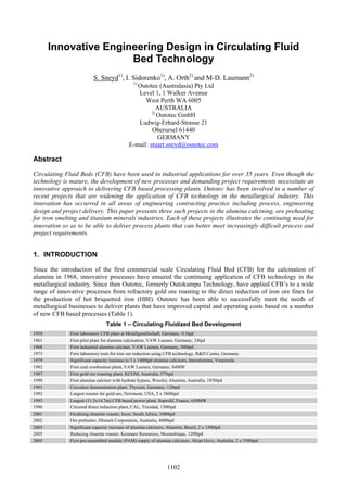
- 1. Innovative Engineering Design in Circulating Fluid Bed Technology S. Sneyd1), I. Sidorenko1), A. Orth2) and M-D. Laumann2) 1) Outotec (Australasia) Pty Ltd Level 1, 1 Walker Avenue West Perth WA 6005 AUSTRALIA 2) Outotec GmbH Ludwig-Erhard-Strasse 21 Oberursel 61440 GERMANY E-mail: stuart.sneyd@outotec.com Abstract Circulating Fluid Beds (CFB) have been used in industrial applications for over 35 years. Even though the technology is mature, the development of new processes and demanding project requirements necessitate an innovative approach to delivering CFB based processing plants. Outotec has been involved in a number of recent projects that are widening the application of CFB technology in the metallurgical industry. This innovation has occurred in all areas of engineering contracting practice including process, engineering design and project delivery. This paper presents three such projects in the alumina calcining, ore preheating for iron smelting and titanium minerals industries. Each of these projects illustrates the continuing need for innovation so as to be able to deliver process plants that can better meet increasingly difficult process and project requirements. 1. INTRODUCTION Since the introduction of the first commercial scale Circulating Fluid Bed (CFB) for the calcination of alumina in 1968, innovative processes have ensured the continuing application of CFB technology in the metallurgical industry. Since then Outotec, formerly Outokumpu Technology, have applied CFB’s to a wide range of innovative processes from refractory gold ore roasting to the direct reduction of iron ore fines for the production of hot briquetted iron (HBI). Outotec has been able to successfully meet the needs of metallurgical businesses to deliver plants that have improved capital and operating costs based on a number of new CFB based processes (Table 1). Table 1 – Circulating Fluidized Bed Development 1959 First laboratory CFB plant at Metallgesellschaft, Germany, 0.5tpd 1961 First pilot plant for alumina calcination, VAW Luenen, Germany, 24tpd 1968 First industrial alumina calciner, VAW Luenen, Germany, 500tpd 1973 First laboratory tests for iron ore reduction using CFB technology, R&D Centre, Germany 1979 Significant capacity increase to 3 x 1400tpd alumina calciners, Interalumina, Venezuela 1982 First coal combustion plant, VAW Luenen, Germany, 84MW 1987 First gold ore roasting plant, KCGM, Australia, 575tpd 1990 First alumina calciner with hydrate bypass, Worsley Alumina, Australia, 1850tpd 1991 Circodust demonstration plant, Thyssen, Germany, 120tpd 1992 Largest roaster for gold ore, Newmont, USA, 2 x 3800tpd 1993 Largest (11.5x14.7m) CFB based power plant, Soprolif, France, 650MW 1996 Circored direct reduction plant, CAL, Trinidad, 1500tpd 2001 Oxidising ilmenite roaster, Iscor, South Africa, 1000tpd 2002 Ore preheater, HIsmelt Corporation, Australia, 4000tpd 2003 Significant capacity increase of alumina calciners, Alunorte, Brazil, 2 x 3300tpd 2005 Reducing ilmenite roaster, Kenmare Resources, Mozambique, 1200tpd 2005 First pre-assembled module (PAM) supply of alumina calciners, Alcan Gove, Australia, 2 x 3500tpd 1102
- 2. Innovative Engineering Design in CFB Technology Sneyd 2. PROCESS INNOVATION 2.1. Ore Preheating Many metallurgical processes produce offgas that contain significant amounts of chemical and sensible energy. Without the effective utilization of these streams these processes would not be as efficient and economically viable as necessary. However these streams are often difficult to handle as they are usually hot and dust laden. One such example is the HIsmelt® process for the direct smelting of iron ore fines with coal for the production of hot metal. Smelting offgas from the smelt reduction vessel (SRV) is typically at temperatures of around to 1000 to 1100°C and can contain dust levels of approximately 20g/Nm3. Furthermore the offgas stream contains significant quantities of chemical energy in the form of CO and H2. Normally the utilization of such a process stream directly in a fluidized bed system is difficult due to the large quantities and poor quality of the gas stream. Outotec developed a specially modified CFB reactor that specifically addresses the issue of utilizing such a hot and dust laden gas stream. A so-called annular fluidized bed (AFB) consisting of a central nozzle surrounded by an annular fluid bed was incorporated with a traditional CFB reactor. This allowed the smelt reduction offgas to be introduced into the base of the CFB reactor via the central nozzle. The annular fluid bed surrounding the central nozzle allows for a good contact of cooler reactor solids with the hot dusty offgas stream thus allowing for a rapid quenching effect to occur. This design also minimizes the amount of clean fluidizing gas for the CFB reactor nozzles to less than 20% of the total gas flow required for proper fluidization. This modified CFB reactor forms part of an ore preheater plant that preheats iron ore fines before injection into the SRV by recovering heat from the SRV offgas. This plant is currently in operation in Western Australia (Figure 1). Figure 1 – Annular fluidised bed and iron ore preheater, Western Australia Other novel applications of this reactor type have included a direct reduced iron (DRI) solids preheating system for the Circored® process where preheated hydrogen gas is used to heat fine DRI to over 720°C before hot briquetting. Currently a new application is currently under construction in Mozambique for the Moma Sands mineral project. High temperature reducing offgas at around 1200°C, generated in a combustion chamber, is used in a magnetizing roasting process for ilmenite. After such treatment in the CFB the ilmenite, an iron-titanium oxide mineral, is reduced to a state, where it exhibits ferromagnetic properties, which are required to separate chromite, a contaminant in the downstream pigment production process (Figure 2). Through the application of the central nozzle design it is possible to use a high temperature reducing gas with lower offgas volume and hence higher energy efficiency. The Moma Sands ilmenite roaster is the first application of a CFB system for magnetising roasting under reducing atmosphere. 1103
- 3. Innovative Engineering Design in CFB Technology Sneyd Figure 2 – Principle of magnetising roasting and chromite removal 2.2. Circofer® Process Another innovative application of CFB technology is the Circofer process (Figure 3). In this process, iron ore fines are directly reduced with coal to produce direct reduced iron (DRI). The process can be configured as either a two-stage process utilising both a CFB and FB for the production of highly metallized fines for DRI/HBI production or as a single stage CFB based process. The single stage process is ideally suited as a pre-reduction step for smelt reduction reactors such as a SAF or the HIsmelt SRV for the production of hot metal. The product from the two-stage process has a metallisation of greater 93% and would be ideally fed to an electric arc furnace to produce steel. In both configurations a specially modified CFB is central to the process in which an additional integrated reactor acts as a heat generator by partially combusting coal with oxygen external to the CFB thereby minimizing re-oxidation of metallised fines in the CFB. This coupling of the heat generator with a CFB allows for increased productivity of the reduction process and thereby results in improved operating efficiencies and reduced capital costs. The process has been successfully demonstrated at pilot scale using Outotec’s 700mm CFB 5tpd pilot plant in Frankfurt am Main, Germany. Numerous campaigns have been operated with various ore and coal combinations so as to develop a process-operating window for commercial design. Figure 3 – Flowsheet of the Circofer process 1104
- 4. Innovative Engineering Design in CFB Technology Sneyd 3. CONTINUOUS ENGINEERING DESIGN IMPROVEMENT In the early 1960s Lurgi Metallurgie (then Outotec) started developing CFB technology to apply to the calcination of alumina, the final step in the alumina refining process. Since construction of the first commercial CFB calciner in 1968, this technology has gained wide acceptance and is recognized as the standard process for alumina calcination. Outotec has been the market leader and has designed and constructed worldwide more than 50 alumina calciners ranging in capacity from 500 to 3,500tpd. The following advantages of the CFB calciner plants have been proved in many reference plants: • Low specific energy consumption • Low maintenance cost and high availability • Wide range of part load operation with extremely stable and easy plant operation with no need for sophisticated control equipment • Uniform product quality with easy and reproducible change of product quality if required • Low Nox emission Outotec is continuously striving to excel in calciner design beyond market expectation, and in recent years has focused on further improving reliability, availability and ease of operation. In one area, the application of advanced castable materials instead of brick refractory lining and use of finite element analysis (FEA) for the calculation of stresses on vessel walls combined with refractory have resulted in improved availability factors above 95% and have lead to the extension of calciner operation campaigns of up to 36 months (Schmidt et al, 2005). The first-generation of the CFB calciners with capacities up to 850tpd were equipped with waste gas fans, which allowed the plant to operate under negative pressure. In these 74m-high calciners the electrostatic precipitators (ESP) were used for waste gas cleaning only and the main hydrate flow was separated by two cyclones arranged downstream of the first preheating stage. The need to reduce capital cost led to the second-generation calciners and resulted in a more compact arrangement, using significantly less structural steel. This arrangement is successfully demonstrated by five 36m-high calciners with capacities of 1,500 (3), 2,000 and 3,100tpd, built in Western Australia. In these calciners the total product flow is separated in the ESP and the two cyclones are not required. The total plant operates under positive pressure and does not require a waste gas fan. However, the positive pressure requires more attention to avoid cracks and alumina leaks. The following design features were applied to the second-generation large calciners to avoid cracks and leakage: • Design pressure safety margin above operating pressure and interlocks for each vessel and duct • FEA stress calculations • Full penetration welding joints • Reduction of moving parts and improved shaft seals The economic expansion of existing alumina refineries to more than 3 million tonnes of alumina per year requires the installation of large calciners up to 3,500tpd. Importantly for the plant operator, these calciners have proven in Australia and Brazil to be easier to operate and control than their predecessors. Recently Outotec was involved in the supply of two new 3,500tpd calciners in Northern Territory of Australia. The following engineering developments, partly proven in other applications, were incorporated into the design and are anticipated to provide further benefits to availability and operability: • New blower concept with centrifugal blowers • Improved fluidizing nozzles and invention of soft fluidization nozzles • Automated continuously on preheat burner and dual fuel injection system • Application of pre-assembled module strategy (Section 4 below) 1105
- 5. Innovative Engineering Design in CFB Technology Sneyd As in every other fluid bed application, reliable supply of fluidizing air is extremely important for the optimum performance of the CFB calciners. Previously, positive displacement blowers were used for this duty. However, the increased air demand and the current maximum size of the blowers mean that 8 positive displacement blowers would be required for a large calciner. Applying centrifugal blowers instead, the number of blowers can be reduced to four: • Primary air blower delivering air for the fluid bed furnace • Secondary air blower delivering fluidizing air for the fluid bed cooler and all seal pots • An additional air blower • Airlift blower for the hydrate airlift In more detail, the latest engineering developments mentioned above are described elsewhere (Missalla et al, 2007). 4. PROJECT DELIVERY AND MEETING THE CHALLENGE OF REMOTE LOCATIONS The new calciners for the expansion of Alcan Gove alumina refinery in Northern Territory of Australia have marked another milestone in the development of Outotec CFB calciners. Due to the site remote location with limited infrastructure and resources, a special installation concept of pre-assembled modules (PAM) was applied for the first time to a calciner (Bligh et al, 2006). With limited accommodation in the small remote township of Gove and the infrastructure incapable of supporting a major expansion construction force, Alcan concluded that the logical solution was to fabricate and assemble the plant into large modules off site and then ship them to site for final assembly. These PAMs were built in South-East Asia and then transported by ship to Gove (Figure 4). The important challenge was to design and construct the largest possible modules to a high level of completion prior to shipment, involving structural, mechanical, piping, refractory lining, instrumentation and electrical disciplines, in order to minimize on-site construction. This successful approach also enabled Alcan to continue production with minimum interruption by the installation process. Figure 4 – Calciner PAM arrives on site For success in this new field for the Outotec’s German-Australian design team, close cooperation between the team, Client, refractory suppliers, installers, consultants and other specialist groups was necessary. Facing the challenge of maximizing the cost and construction efficiency of the PAM concept, the team had to work simultaneously on the calciner design improvements and on the maximization of the PAMs. 1106
- 6. Innovative Engineering Design in CFB Technology Sneyd As a result, two giant modules per each calciner were constructed and included fully refractory lined process vessels, rotating equipment, electrostatic precipitator, piping as well as electrical, instrumentation and control equipment. After the construction the modules had to be safely shipped to Gove. The modules were enormous, the largest weighting 2,028t, towering 40m high and spanning 23 by 24m, and were welded onto the ship’s deck. The final challenge was to unload the modules and move them to their installation location. With uphill gradient of 6% and downhill gradient of 5%, the land transportation of the modules was carefully monitored to ensure constant proper support until they were securely fastened to their foundation, only 19 months from the start-up of engineering. The second calciner modules arrived in Gove three months later. Remote coastal locations are perfect for this plant delivery approach and, since these locations are also optimal for alumina calciners, PAM concept promises advantages in the future. If PAMs are split up into independent units, pre-commissioning and cold testing can be done offsite. This approach can reduce commissioning time and cost on site, and minimize impact on production. 5. FUTURE DEVELOPMENTS It is hard to imagine that further significant improvements in CFB design are still possible after over 30 years of continuous improvement. However, the following new applications and improvements are currently studied and may become future standards (Orth et al (2007)): Circoroast® The next generation of sulphide ore roasting addresses an increased focus on environmental and maintenance friendly reactor design. The compact combination of roaster reactor, recycle cyclone, waste heat boiler and fluidized bed cooler provides maximum efficiency in heat recovery and results in reduced investment and operating costs. Clay calcination Calcined clay can be mixed in a ratio of up to 40 % with Portland cement to supplement production whilst maintaining quality. The calcination temperature for the clay is significantly lower than the production of equivalent Portland cement leading to considerable energy savings. Using the CFB calcination process organic and inorganic compounds are removed to achieve a homogenous high quality intermediate product for further downstream processing. Circotherm® Where applications require intensive mixing between solids and hot dust-laden gases, a special reactor design is needed. Circotherm is ideally suited for the quenching of hot offgases with solids, as well as condensing vapours contained in offgas streams that are difficult to handle. The core system comprises an AFB with integrated heat recovery systems and a solids recovery cyclone. 6. REFERENCES Bligh R., Klett C. and Parthasarathy T. (2006), Calciners go sailing – Pre-assembly by Outokumpu Technology pays off, Aluminium, 82 (9), 854-857. Missalla M., Klett C. and Bligh R. Design Developments for Fast Ramp-up and Easy Operation of New Large Calciners, Light Metals, TMS. In press. Orth A., Anastasijevic N. and Eichberger H. Low CO emission technologies for iron and steelmaking as well as titania slag production, 2Minerals Engineering, Vol.20, in press. Schmidt H-W., Stroeder M., Singh G., Sant’ana M., Ribeiro J., Piestrzeniewicz J. and Cable M. (2005), Improved Health and Safety Conditions and Increased Availability in Large Alumina Calcining Units, Light Metals, TMS, 251-255. 1107