Download as PDF, PPTX
![SnnucrrlRAr', ExcrxnERrNG
tr'onuul-,AS
COMPRESSION . TENSION . BENDING . IIORSION . IMPACT
BNAMS ' FRAMES . ARCIIES . IIRUSSES . PLA.IES
FOUNDATIONS . RE||ATNING WALLS . PIPES AND TUNNELS
ILYA MrriHBr,soN, PII.D'
ILLL]SITRATIONS BY LIA MIKISLSON, M.S.
MCGRAW.HILL
NE$,YORI< CIIICAGO SNF'RANCISCO LISBON LONDON MADRID
MEXICO CITY MILAN NES'DEI,HI SAN JUAN SNOUL
SINGAPORT SYDNEY ITORONIIO
.'..](https://image.slidesharecdn.com/structuralengineeringformulas-160419150544/85/Structural-engineering-formulas-1-320.jpg)
![SnnucrrlRAr', ExcrxnERrNG
tr'onuul-,AS
COMPRESSION . TENSION . BENDING . IIORSION . IMPACT
BNAMS ' FRAMES . ARCIIES . IIRUSSES . PLA.IES
FOUNDATIONS . RE||ATNING WALLS . PIPES AND TUNNELS
ILYA MrriHBr,soN, PII.D'
ILLL]SITRATIONS BY LIA MIKISLSON, M.S.
MCGRAW.HILL
NE$,YORI< CIIICAGO SNF'RANCISCO LISBON LONDON MADRID
MEXICO CITY MILAN NES'DEI,HI SAN JUAN SNOUL
SINGAPORT SYDNEY ITORONIIO
.'..](https://image.slidesharecdn.com/structuralengineeringformulas-160419150544/75/Structural-engineering-formulas-1-2048.jpg)

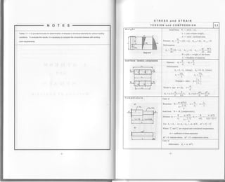
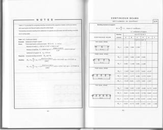
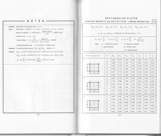
![Tables 1.2 and 1.3a
Example. Bending
civen. Shape W 14x30, L=6m
Area A=8.85in'? =8.85x2.54'? =57.097cm2
Depth h=13.84in=13.84x2.54=35.154cm
Web thickness d = 0.27jrn = 0.27 0 x 2.54 = 0.686cm
Flange width b=6.730in=6.730x2.54=1'7.094cm
Flange thickness t=0.385in =0.385x2.54=0.978cm
lvloment of inertia I. = 29 hn' = 29 x 2.5 4' -- l2l 1 2 -3cm"
Section modulus S= 42.0inr =42.0x2.541 =688.26cm1
Weight of the beam ro = 30Lb /ft = 30x 4.448 I 0.3048 = 437.8 N /m = 0.4378 kN / m
Load P=80kN
Allowable stress (assumed) [o] = 196.2 MPa, [r] = 58.9 MPa
Required. Compute: o.,"* and x."*
..rT 2 DT
Solution. M = A+l:
84
-, (DL P
22
_ 0.4378x 6,
+
80x6
= 12 1.97 kN .m
84
0 4378'6
*
8o
= 4t.3t kN
o.,o, _ tvt _ 121.97x100(kN.cm)
s 688.26(cmr)
22
17.72 kN/cm': =177215.0 kN/m'?=177.215 MPa< 196.2MPa
I .1t90 kN/crn' - llJ900 kN/m' = 18.9 MPa < 58.9 MPa
STRESS and STRATN
BENDING 1.2
".. lt I
rr-q;r_
%l^I
T---_]______T t
--T;Z'u* =?
Moment diogrom
*-------= v=f
Sheor diogrom
"!4,.
Stresses ?f----r:
in''ti"o-ii-.n"ion" 9rj I ll-e
zi.zll ljra,
-11""
F---iq-E;Fiq-- I
lsvl
t!-^tfg{^-L,| ,A1,sv I
lzl
#
u L ue0d am fd
E+ h l+E ffi,€
E E A-E.E_'E
I -g4gLBH PtrE
BEIEEEE
RH=EEItr
""€ F*R I e-,8
Stress diogroms
4
bcndtngslfcss; o--.)
I
^. VS
Jnetrstress: T=-
l.b
Stresses in x-y plane:
oy = 0, o" = 6, 1., ='tv ='c
Principal stresses:
o l/ .
o'^. -:l r/o'4r':
Maxjmum shear (min) stresses:
l/'_
r,,"" =t;Vo,'+4r'
il/
The principal stresses and maximum (min)
shear stresses lie at 45' to each othcr.
Stress diagrams
o-diagram:
"" =*T, "".=0, ",,=-{
t-tliagram: {", =0, ri" =#=#, "",
=t
o,""" -diagram:
q =*+, o", =+r=+!I, o,, =o
o,.," -diagram:
^3VM6..,U,6 _-T=--" O ___
24 S
T,,,, -diagram:
oM3Vi =I - t-=r-. T _rt-+_
22S2A
t,",,, -diagram:
oM3Vt. -T j r- - t-- -22S2A
Note;
"+ "- Tension
"- "- Compression
:-](https://image.slidesharecdn.com/structuralengineeringformulas-160419150544/85/Structural-engineering-formulas-9-320.jpg)
![STRESS and STRATN
VS
ess: T=-
I,b
h ) b/h'z .)
;+Y l=;l ;-Y' I'z / L+ )
"'J') 6v(t' ,)
bh'14 ')
0, for y=9; x=
v. /h t)
'r,d 2 2)
./ h ''lol
t-'l I
)l-l
l
ear str(
(h )rl
l;-Yll ;
b(h'
i[7-'-thr.
_.b
t2
,h
2
lr =0,
fh r)
lt-t)'
fh r),
lt-t)-
She
. =!(_y
zl
b/ Tl
-i-bt I
r,b I
tl
Iiu,[
r,dl
I
al
f
Case
Bending moments.
tvomentduetoforce e' V=nln4 + nt',
M.=Mcoscr, Mr=Msino,
[l!l = r,-or
LM.]
For case shown: M, = PyLcos d, M, = {Lsin o,
M=PL
o-r MIY'9'0
'f=-s I
r"lr)Stress:
- ,M( s- )
""",
=.
tl
cosq+ fsindJ
Neutral axis: tanB=Ia1uno.
ly
Deflection in direction of forc" f
'
A = UI{ +{,
E^. ^--^ -L^...-. ^
P,L' P' L'
For case shown: L. = :!L. A =
') -
' 3Et.. lEr
BENDING
n two directions
==-](https://image.slidesharecdn.com/structuralengineeringformulas-160419150544/85/Structural-engineering-formulas-10-320.jpg)
![STRESS and STRATN
COMBINATION OF COMpRESSTON (TENStON) and BENDTNG 1.4
uompressron (Tension) and bending
stresses: o=* t Yt tYr,A I, I""
PM,M6=_t:+-';lJ A - s, - s,'
M,=P e", M,=P e,
hb' b.h, ^ h.b, ^ b.h,
= 12' ''=-r'
t,=
6 ' t'=
n
i' i'
Neutral axis: y,,=lz, z"=!.
"Y "r'
i,= Jr) A, i" =r/i7a, a=u.rr
]-i f t +)
-lil {l ll lt
'+ + {+ffi
Euler's formula:
^ n'EI liP.= ,= for 1..,,)n,/^:..
(kr)' v R.
where R" is the elastic buckling strength.
. kL -1r1., -ilj1. stress: o.^ Saj.
Axial compression (tension) and benl
x
| ,
^{lb
Stresses:
compression o.," =
tension o.*
where : Mo and Ao: max. moment and
ma. deflection due to transverse loading
NMoNa,,
A-q'tJ
P"
NM"NA^
A S, S. , N'
P.
-9-](https://image.slidesharecdn.com/structuralengineeringformulas-160419150544/85/Structural-engineering-formulas-11-320.jpg)
![Table 1.5
Example, Torsion
civen. cantilever beam, L = 1.5m, for profile see Table 1 5c
h=70cm, h, =30cm, h, =60cm, h, =40cm, br =4'5cm, bz=2'5cm, br =5 5cm
Material: Steel, G=800kN/cm'? =8000 (MPa)
Torsion moment M, = 40 kN 'm
Required. Compute '[* and q"
h1n
Sofurion. !=i::=O.Ol . 10. cr =2.012,
br 4.)
lt=9=z+r 10, !-=4= 7.27 <10, c,=z.zr2
b2 2,5 br 5.5
1,, = c,$l = 2.91274.5a = 825.04 cma, I'. = c,6l = 2 212v 5'5a = 2024'12 cma
h hr 6ov? 5l
I, =",.', ="":" =312.5cma, lI,=t,, +t,,+I,.=3161.66cm4
t, =,
t' =tt9tjuu =574 85 cml'.h5.5
40x{100)
t.- = IY1L1II1= 6.958 kN/cm'? = 69580 kN/m'? = 69.58 MPa
.no _ 180. M,L _ 180 .40x(100)x1.5x(100) - 13.60
* n Gl, 3.14 800x3161.66
STRESS and STRAIN
roRStoN lr.s
o/.
b/.
r,,
ll-T-r
'* .'klo
[dJ"
lLnox
,-=.f g
Eot
I=rD
Bar of circular cross-section
Stress: , =M'.9=M,I ) q'-p-"n
, fido ^ rdlIo=-=.9.16'. So=-:" =0.2d'.
Angle of twisr: eo -
180". M L.
n Clo
Where G = Shear modulus of etasticity
Bar of rectangular cross-section
Str.rl t*^l{'. Angleolrwist: ,o-
1800.M'L.
s,ncl
rr h->ro:
,=T. r =i=T
tr !<to: I, -c .b'. S, -c,.b,.t)
ln point l: tr =T.u", inpoint 2: ,c2=c1.,t^,,.
t, /h -
a,
c2
cl
1.0 l.J 2.0 3.0 4.0 6.0 8.0 10.0 For
h/b>10
0. r40 0.294 0.457 0.790 123 L789 2.4s6 3.t23
0.208 0.346 0.493 0.80 1.150 1.789 2.4s6 3.123
1.000 0.859 o.795 0.75 0.'745 0.'743 0.742 0.742 0.740
c/. F_h-
r=ts-F--t-{
l"-tir*r
-l ; '+l- *l
l.aH;#-TTE]
'F-i-
fl"
". [J''
=
EFi rndt
Profile consisting of
re cta n g u I a r c ro s s - s e c t i o n s
i=n
Ceometricproperties: ,-I' . g =-l' . n=3
Assumed: .t0, lrrto b.;;
Dr b: b3
b,>b, , b, >b, (i.e. b, =b,""")
t,, -crbi . I =
h,bl
r,. =c,b1 .
I, =Ir, +I,, +I,,, S. =
I,
.
' b,'
Stress: t,,. =!!r linpoint t.1.
sr
Argle of twist: go -
180'
'
M'L.
rc GI,](https://image.slidesharecdn.com/structuralengineeringformulas-160419150544/85/Structural-engineering-formulas-12-320.jpg)
![C u rved bea m (lransverse bending )
C u rve d bea m (axialforce and
STRESS and STRAIN
CURVED BEAMS
oI
Stresses:
- M y-R,,
" _leo. =-.-, h"_
' A.c y "
tA'
c=R_Ro
hl
lf :<0.5. c=--j! forallcross-secrionlypes.
R A.R
For case shown:
A =Ar +Ar,
M R._R"
'A.c R,
"+o " - Tension
"*o '' -Compression
^. N. M o-R"SreSSCS : O^ =
-+ -'AA.cRo
Forcaseshown: c=R-Ro,
N=P, M=2PR,
_ P zPR R, -Ro
-' bh bhc R"
_ P ,2PR R"-Rb
" bh bhc Rb
Note. For beams with circular cross-section:
,( | r) f '.,''rn.--ln+,/n'-a I o' no=nlr-'l*l .
z r *., L l6R/]
d = diameter of cross-section.](https://image.slidesharecdn.com/structuralengineeringformulas-160419150544/85/Structural-engineering-formulas-13-320.jpg)
![STRESS and STRAIN
.b'
dh
"tl
3NE'l6n
'qae
[i .6 xo
9^ll
8 =!'
E.9
",q'0 h.H;iEA
.E6tl
X ^e+N
"9,. .6
oP
E=
r
,tvt
c
nl
d
o
6
o
o
o
Tabl,e 'l
"7
Example. Continuous deep beam
Given. Beam L=3.0m, h=2.0m, c=0.3m, thicklessb=0'3m, w=200kN/m
Required. compute Z, D, d, do and d.,,* forcenterofspanandsupport
Solution. Atcenterof span:
Z =D = a.xljwL= 0.186x0.5x200x3 0 = 55.8 kN
d= oo x0.5L=0.888x0.5x3.0=133 m
d0 = cdo x0 5L = 0 124x0 5x3'0 = 0 19 m
o.* = ct. x w / b = 1 065x200 I 0.3 = 7 I 0 kN/m'] = 0 71 MPa (tension)
At center of support:
Z = D = cr, x0.5wL = 0.428x0.5x200x3.0 = 128 4 kN
d = aa x0.5L = 0.656x0.5x3.0 = 0-9tt4 m
do = 0(a. x 0.5L = 0.036x0.5x 3.0 = 0 05 m
o,."- = ctd x w / b = -9.065 x 200 / 0.3 = -6043.3 kN/m'? = -6'04 MPa (compression)
0
I
{
[,
m
UJ
U
a
o
t
ts
t
o
(J](https://image.slidesharecdn.com/structuralengineeringformulas-160419150544/85/Structural-engineering-formulas-14-320.jpg)
![Tables 1.8-1.1 2 consider computation methods for elastic systems only
STRESS and STRAIN
DYNAMICS, TRANSVERSE OSCILLATIONS OF THE BEAMS 1.8
NATURAL OSCTLLATIONS OF SYSTEMS
WITH ONE DEGREE FREEDOM
1 SIMPLE BEAM WITH ONE POINT MASS
Dettections
N
1 Y
r-
ffid;1,;lt-+FORCES:
l'-Weight oftheload, M"""' .=3
g
( ^^.cml!-cravitationalacceleration.l g=981 ;
sec'/
11 - Force of inertia, P, = T ma
il = acceleration
For shown beam:
Maximum Bending l,4oment
.. a.b M
M.- =(Pr q).-, Stress: o= jje.t
I I,
DEFLECTIONS:
A.r =Static deflection due to Load p
aA =Max., min. deflection due to Force P
A,t(r) = Static deflection due to Force P = 1
c=amplitude, c=1Ai
MaximumShearfor a>b
V =/P+P '1
stress: t=* S
.t
v
l)eflectionsN
I
-rz!-
ffi*^| --1---- |
i-t--*-f-.
Forceofinertia: C=4+
lvlaximum Bendins Moment: Mh"* =[tP-t,) ;
Maximum sheari
"-
=;[ry.t)
Deflections- I
=- ----'r,
1__?| , ---l
?eFI
Forceofinertia: P, =7
Maximum Bendins Moment: Mnu =(+.t] t
Maximum shear: v,"- =
3"#I'*r](https://image.slidesharecdn.com/structuralengineeringformulas-160419150544/85/Structural-engineering-formulas-15-320.jpg)
![STRESS and STRAIN
DYNAMICS, TRANSVERSE OSCILLATIONS OF THE BEAMS
DIAGRAM OF CONTINUOUS OSCILLATTONS
Equation of free continuous oscillations: y = csin (rot + <po
)
Where: ou =initial phase of oscitlation, O" = -..in[&]
c,/
c0=amplitude, t=time, T= periodoffreeoscillarron, l=4=ZnN-
Ie
o = frequency of natural oscillation, . =
E
DIAGRAM OF DAMPED OSCILLATIONS
Equation of free damped oscillations: y = coe
*t,' . sin ( rot + <po
)
F-----'-=-
co =initial amptitude of osciilafion " - /,,r *f vo + yok 2m )'
' *-!r,-l , .j
Q0 =initial phaseof oscillation, Qo =rcsinl & l, t. =initiat deflection
co,/
v0 =beginner velocity of mass, e =logarithmic base, e = 2.7 1828
k = coetficient set according to material, mass and rigidity
T = period of free oscillations, T =2ja I 0t
-
o = frequency of free oscillation, ro= a/r/ rn- [k/ 2m]', For simpte beam](https://image.slidesharecdn.com/structuralengineeringformulas-160419150544/85/Structural-engineering-formulas-16-320.jpg)
![STRESS and STRAIN
DEFLECTIONS:
A,* -A*(p) +A$G) +Ai
Aq(p) =Static deflection due to Load P
A,r(,) = Static deflection due to Force S
Ai =Static deflection due to Pi ,
Ar = Pi .A*(rl
DYNAMICS, TRANSVERSE OSCILLATIONS OF THE BEAMS
FORCED OSCILLATIONS OF THE BEAMS
WITH ONE DEGREE FREEDOM
SIMPLE BEAM WITH ONE POINT MASS
qY
TORCES:
l' -weishtoftheload. tvtass, m=1. [*=oS'li 1
g sec-)
S(t) =vibrating force, Assumed: S(t)=5q.rt
ll =Forceof inertia, q =A'1'-A-5"o.11' Astr
rp-Frequency of force S(t)
A.,t
) = Static deflection due to Load P = I
Equationof forcedoscillations: y=c e-'' " ,in1rt*,po1+-ffQ .or,pt
c. e-t' " sin (ot + g0) =free oscittation. :jj!]]- costpt
f((D'-a-J
e0 = beginner phase of oscillation, ,1, = *..i" f
bl , y0 = beginner deflection
co.i
co=amplitudeof freeoscillation, co =c, c=amplitudeof forcedoscillation, c=ko.A.,,.,
:k = coefficient set according to material, mass and rigidity
o = frequency of natural oscillation, T = period of oscillations, T = 2n / or
kn =dynamiccoefficient. k" =#
./f'-ql'*[k q,l'
il rUJ') Lm (o"l
lf k = 0 (damped oscillation is not included 1: ko = -_L
,vt-tt
e=logarithmicbase, e=2.77828 /e=sgf
"t ). g=gravitational acceleration.
[_ sec_/
forced oscillation](https://image.slidesharecdn.com/structuralengineeringformulas-160419150544/85/Structural-engineering-formulas-17-320.jpg)
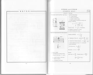
![Table 1.11 Dynamics, impact
Example. Bending
Given. Beam W12x65, Steel, L=3.0m,
Momentof inertia I.=533in4x2.54o =22185 cm*
Section modulus S = 87.9 in3 =87 -9x2.543 =1440 4 cmt
lvf odul us of elasticity E = 29000 kip / in: -
29000-!j8222
= 20 1 47.6 kN/cm']
' 2.54'
Weight of beam (concentrated load):
W = 65 Lblftx3.0 = 195x4.448/0.3048=2845.1 N = 2.8457 kN
Load P=20kN, h=5cm
Required, Compute dynamic stress o
sorution. A. -
PL'
-
20x(l' 100) - =0.025 cm
" 48E1, 48x 20147.6' 22 I 85
Pr lo ' I ,20.4 - loo kN .mBendingmoment V,,-
O:
ku-
O
51r"". o=Y.= 306*100
=21.24 kN/cm'? =212400kN/m'=212.4 MPa
s 1440.4
Table 1.11 Dynamics, impact
Example. Crane cable
civen- Load P=40kN, velocity o=5m/sec
cable: diameter tl=5.0cm. A=19.625 cm', L=30m,
Modutus of etasticity [r = 29000 krp/ iDr = ?249rji922? = 20147.6 kN/cm'?
2.54'
Computedynamicstress o forsudden deadstopRequired.
Solution,
4",
Stress:
PL 40x3(r(l0lr)
- t,.-{t,) cm, k - -j- =
EA 20t47.6y 1q.625 Jg 1'
o=
P
(i*k^)= 40 (l+2.9=7.g49kN/cm'? =79490kN/m'? =79.45 MPa
A ' 19.625 '
STRESS and STRAIN
DYNAMICS. IMPACT
Elastic design
Axial compression
Bending
Crane cable
tt
It
- ff-r
t= strking velocity, , ='Dgt
g: earth's acceleration, g =9.81 m/sec'?
A*= deflection resulting from static load P
W= weight of the structure
B: coef'ficient for miform mass
PL^Itsor snown @lumn:
",
= go . p =
J
P
lr)mamrc stress: o=-;.KD.
For shown beam: a' =
Pt'
B=11
" 48EI,
.
35
Dynamic bending moment: MD =I! k .
P
Dlmamic shear: Vu =
t
ko .
For stresses see Table 1.3
Sudden dead stop when the load P is going down.
Dynamic coefficient:
,UKD =-1==_- ,
vg
^",
whete: o: descent's velocity,
PI
EA.
Maximum stress in the cable:
p
6=_(t+ko)
A
A = area ofcable cross-section](https://image.slidesharecdn.com/structuralengineeringformulas-160419150544/85/Structural-engineering-formulas-18-320.jpg)
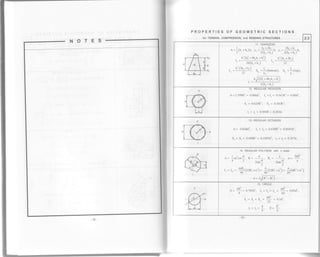
![PROPERTIES OF GEOMETRIC SECTIONS
for TENSION, COMPRESSION, and BENDING STRUCTURES 2.1
I
r-T--?--.r
{ l.t l-"
'tfr-*'
1. SQUARE
^4 ^1
A-ar. t,=t"-i- t,=1
r.= t - ? ,.= ,, - ,fu.=
o.zr ,^ , ,=
+
ffi*
2. SOUARE
Ais of moments on diagonal
^ ^2 L-^ l;, t tt^
4l
A- a-. h= avl- t.42a. L,= l, - ;:. S.= S. _ *:== 0. I l8ar
L2 6J2
."=. = -!- o.:tsa. z- -3-=o.zlea
./r2 3J2
ll x,
rtTY
-l],I'd(l-"
*
'[ *'l' .'
3. RECTANGLE
, bh' bjh bhr brh
^12'12"3',|
hh2 h2h
S -;. S -;. r,-0.28ch. r,= 0.289b.
b6
d'sina
48
ry'
4. RECTANGLE
Axis ofmoments on any line through centerof gravity
I
A= bh. y, - y"- -1h cosa - b sina).
2'
hh _ bh (h?cos':a t b) sin2 a)I, - ,; (h'cos'a'b'sin'a). S
-
tz " 6(hcosa+bsina)
., " o.zso6'"oJ* btin'al
r-T+1I T--]lr-
11- _'--
--[il
A= ah + b(H - h),
t,:
$. fe' -o'r, r,=
* *$o-nr,
s.:
Su'-r"r* #, r,=
* *
frr-nr
rlY
t"i--| lT---T'-'-'1---:-T
tffi|
6. NONSYMI,IETRICAL SHAPE
A=bc, +a(ho +h,)+Bco, b,=b -a, B,:B-a,
aH']+ B,c,+ b,c.(2H - c. )
2(aH + Brcb+ brc,) ' rt " Jh '
t_
I, - ;(By; - B,hl+ ur' - o,nr,
J
-29](https://image.slidesharecdn.com/structuralengineeringformulas-160419150544/85/Structural-engineering-formulas-21-320.jpg)
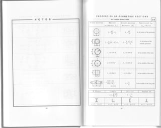
![PROPERTIES OF GEOMETRIC SECTIONS
for TENSION, COMPRESSION, and BENDING STRUCTURES 2.2
7. ANGLE with equal legs
. h2+htt[t hrr-2cA- t(rn - t)' y -
2(2h - t)cos4f ' t'=
-E-'
t"= llzc'-z1c-tY *tq'-2.* ]ty''l- 3L 2')
c= y,cos45"
",'"lf'r'"nt
h2+hr
A= (b _ h,)_ r(h _ b r. x,_ - "r' . v._ jj______:!-.
2(b h,) -" 2(h I b,)
lr
r^= -lrlr'-y,l tyj -u,(v, -r)'].
lr
t,- lfr1U-xo]'-trx] -tr,1xo -t;']
l, = I.* md I, = 1.,". tun:po = J!' .
l*y= Producr ol inertia abour aes. bb hh L
(moy. r{) =.4(b*hJ,
lt)l
A =-bh , rro =Jh . 1 =:rr. d =1(b, -b. ) .
, bh' , bhr , bhr
-" J6'' t2' 4'
, hb(b,-b,b.) rr(uj+ul)
"= J6
"
= 12 '
hh2 hh) h
S",0, =:-(forbase). S,,,, =
;(lorpointA).
r" =#=0.236h
10. RECTANGULAR TRIANGLE
^ bh cL , bhr hb'
221636
, b'h' Lc3
-v' 361: 36'
or: Ir, = I"cos2a + I*sin2a + 2I*rsina cosa,
.bhbrht
sln,r= -, cosa= -. | = --L' L' " 72'
h
r-= _:+= 0.236h.' 3^12](https://image.slidesharecdn.com/structuralengineeringformulas-160419150544/85/Structural-engineering-formulas-22-320.jpg)
![PROPERTIES OF GEOMETRIC SECTIONS
for TENSION. COMPRESSION. and BENDING STRUCTURES 2.4
I
,/F,-l-'l-;" F l-x
H/I t-dJ I
l----.0--l
16. HOLLOWCIRCLE
*n7 / -n4
n="" (r-E'). E=i. r=r ="" ft_8")
4 'D 64'
u l, .)
5 =5 =_{l*C t. r =r =_.il_r-' ) l1 J I y
'
! >'q
nl
-dJL=-.
6
g-
17. TH|N R|NG (t<<D)
-hl+
A= rDr, t, = 'il ' . 0.3926D'r,
8
S,=
?= 0.7853D']r. r"= 0.351D.
,-l-Tts i - l-{r,I o-zn -l
I
18. Half of a CIRCLE
A= n7
- o.zszo', y6= 0.2122D, y, = 0.2878D,
I- = 0.00686Da, I, = I" = d= O.OrrOo,
s., = o.xtz(!)' -ror bottom, s", = o.rsor[!)' -ro. top.
--'K{
m-Ti
rQz dR
e- |= 0.785R'. y, = #=0.a2an.
y = 0.s76R.
I" = 0.07135R4, I, = 0.03843R"
r" = r, = 0.0548eR'. r,,= r, = f= o.'ru.,r*'
7..-.--- -,^FHl
. 20. Segment of a CIRCLE
nno
= eg b=2Rsina, s= 2Ra,d=
ffi, t!= 2a-sin2a. k= J(p
o = {E. y" =rR. r^ =4t' , J*cosa). 1 =-p{1r-r.ora;.2 '" ^ 8 ' 8 '
(d - in radians measue, a- in degrees).
-35-](https://image.slidesharecdn.com/structuralengineeringformulas-160419150544/85/Structural-engineering-formulas-24-320.jpg)
![PROPERTIES OF GEOMETRIC SECTIONS
for TENSION, COMPRESSION, and BENDTNG STRUCTURES 2.5
I
|-7z'i-
'l lt{Tr-*l;.1
21. ELLIPSE
, lt , zab' Ab' ratb Aa2
A= -aD. I = _=_
46416'6416
- rabt Ab ^ ra'b Aa
).= _= _. 5 =' 32 8 " 32 8'
ba
''
4' r 4
I
|ffir..
11+#42-"
t*t
22. HOLLOW ELLIPS
t= |@a-u,a,),
r. = fr(uu'*u,ri), t, =
ff(u'a-uia,),
s.=
fi-("u'-u,ui), s"=
fr(u'r-uiu,)
I il.l,--:-Ta
-Fl-E[-"
t-*? j
23. Segment of a PARABOLA
^ 4ab 3a 4ab' ab'
;- = -.J f t) )
, I oa'b l2Aa'z , 4a'b 3Aa2
't75t75"71
, 32a3b 8Aa2
" 105 3s
v
-tr6ffi4"
l*i I
24. STEEL WAVES from parabotic arches
r= !tea+s.zt), b, = jtr*r.ut),
u, = ]{u-z.ot), r', =}{r'*,),
r',= j{n-t), r.=
ff(ur'i-u,r,l), r"=
o4
W
25. STEEL WAVES from circulararches
A=(irb+2h)t, hr = h-b,
. (zb' .,. rbh'zt.,lr. -I-Tu IrT-T-il! tr..
t 8 4 6')
^ 2r.
h+t](https://image.slidesharecdn.com/structuralengineeringformulas-160419150544/85/Structural-engineering-formulas-25-320.jpg)

![The formulas provided in Tables 3.1 to 3 1o-for determination of support reactions (R)'
bending moments (lV), and shears (V)*are to be used for elastic beams with constant
or variable cross-sections
Theformu|asfordeterminationofdef|ectionandanglesofdef|ectioncanon|ybeused
for elastic beams with constant cross-sedlons
SIMPLE BEAMS 3.1
-fti=Jl]fi:o No,"*u=*.,n=*,
q md 0b in radians
LOAOINGS SUPPORT
REACTIONS
BENDING MOMENT DEFLECTION ANG LE
OF DEFLECTION
r-i--F-irt___L_{1' Lr 4B-
t Mofnent
lqryl; Sheor ''M-o I
tr%rd'r
P
R_ =:"2
D
D -''2
PI
at point of load
pTl
-* - 48Er
at point of load
pr2
r1 = 19 =-:aI 6EI
b.aL
Momerlt
*qIPl
Sheor l'u.o"l
h
D _D "
"I-
o -o
o
.I,
'* ='+
at point of load
^
Pa2b2
3EI. L
at point of load
I
Dr2
6g1 >t >t /
Dr2
6EI'- -
',
a,b
L' '' I,
I luo-entl ,
ir@i1,,,1 st'"o. j'"'j
''-v
qJ2
D *D _D M.* =Pa
between loads
Pabt -4a'_
24F.1
at center
L*a
2E1
tfr*r-Fl
-r-J+'_l+
Morient I
ro4Pi';heor
|
Mfrf I
|H , r
'2
1p
"2
DT
z
at center
^ PIJ
20.22Er
at center
pr2
24EI
v,lilffi"'*i](https://image.slidesharecdn.com/structuralengineeringformulas-160419150544/85/Structural-engineering-formulas-28-320.jpg)
![Table 3.2
Example, Computation of beam
civen. Simple beam W14x145, L=10 m
Moment of inertia l=1710 ina x2'54a =71175'6 cma
Modurus of elasticitv E = 29000 kip/in': -
29009:1!8222
= 201 47 6 kN/cm'?
Uniform distribution load w =5 kN/m=0 05 kN/cm
Required" Compute V=R, M,*, A',., O=O"=Or
., , -
*L
-
5"lo -_25 onSofution. v =K= 2 =- 2
wr- 5xlo'?
M jjji-= =62.5kN m
88
n -
5.*t'= s 005x(1000)"
=0.45cm=4.5mm
^'*-:94 gI 384 2ol4'7'6x71175'6
*= til
=
o ott(tooo),.t
t =1 45x10
rradim
" - zqql 24x20147.6x71175 6
I Momenr I
iwiln*l I Sheor I
'----VIrlIIIEnv2
SIMPLE BEAMS 3.2
LOADINGS SUPPORT
REACTIONS
BENDING MOMENT DEFLECTION ANGLE
OF DEFLECTION
lllt,tomeftll
lruqtrry;I lshqor 'M;d | '
ruv2
Pn
"2
Pnp--
"2
4 5 6
^ PA 2n2 +l
' 48ET n
^ PA 2n'+1
Dr =-.-" 48EI n
M.* =
PL
^2
PL
1J38
DI
1-333
Pil
19r'4Er
PL,
15IF,J
P]j
t2.65Er
I Moment I
SqI[ruIIFlI srr"o. lu* |
|n]-'*i_ft",
^wL
"2
^wL"2
M
wt
at @nter
: t L-x I
2'
M-
^5wU
384 ET
at center
wx { Lt-2Lx' + xt )
/^" 24Fr
WU
24El
lMoment I
ffi| | Sheor I
o -wdrr rr
" 2'
^ wa"
" 2"
?a
M,"""
al
^ wa'tf. I ")U.. =
-l
l--C" 6Er l 2')
^ wa'L/- l-,
I Mo*nent i
w]N#u.
- wcb
"L
- wca
nr=
L
.. wabc/. c )
r l-
^r
I
L LL)
c{b-a)
2L
=l u(r*'ru'
L
c'L'l R
+-lx-
64b | 6Er
+).
aI x=a
R
"q-__ac
" 24EI
R
"-_'ba
" 24EI
fi =4a(L+b)-c'?](https://image.slidesharecdn.com/structuralengineeringformulas-160419150544/85/Structural-engineering-formulas-29-320.jpg)
![NOTES
SIMPLE BEAMS 3.3
LOADINGS SUPPORT
REACTIONS
BENDING MOMENT DEFLECTION ANGLE
OF DEFLECTION
@.|}, | +:-,-- L -l -wL
"6
-wL
"3
M-"" =
*?=0.064wli
9J3
wnen x=u.)//L
=nno65):
CI
when x = 0.519L
7wC
I Moment I
'wi! sh"o. t.ymol
llTtrrr.* I r
360 EI
8 wli
360 EI
-*--t-
ffiiI Moment I
iql][ryilshuo. u*, I
IITrrrx I
M =*I,,12
at @nter
I 2OEI
at center
) wL-
| 92FI
4rllffi
i iuo-"nt t'
rqIIUPi
l- .n"Ju'* I
- w(L-a)
*,=r5il
wL' wa'
86
at center
5 wl-o
D. =Dr =-.1,
24F,1
c *1 1Y2,tJar - r-29 Ts
384 EI
. _, 8",,16"0rr - r-- T-q
JZi
at cenler
i-;;. IiquuPlI Sheor Mmr I
llTh"*-;",
D _ 2wu +wb,
^"- 6 "
o _ w, +2w0,
'.b- 6
L
wa
o.2 o.4 0.6 0.8 1.0
^ ri (8w, + 7w" )
" 360Er
^ I-r(7w, +8w" l
u.=" 360EI
N/
l3
"09
1130 c% sff
wlf,
8"00
X
L
0.555 0.536 0.520 0.508 0.500
when x =0.500L4","" ={wa+ub)L-,
to x=o.5l9l
r',*l q,",
-*--t-t-rirrrfllnh#-l.tr,I | '7
I Moment I
iql][ryilshuo. u*, I
vrllTFn* ln
v,llTffi- lv2](https://image.slidesharecdn.com/structuralengineeringformulas-160419150544/85/Structural-engineering-formulas-30-320.jpg)
![NOTES
v |Trrrrrrrrrrrrrr
vllrrrrrrr | | | rr rrrrr1t2
SIMPLE BEAMS and BEAMS OVERHANGING ONE SUPPORT 3.4
LOADINGS
SUPPORT
REACTIONS
BENDING MOMENT DEFLECTION ANGLE
OF DEFLECTION
E.-l--"*;l
ffit
R"=+
Ro =-R"
M,,* =M,
when x=0
M.IJ
d."...._
I ).)vbl
when x =0.423L
, M^L,
I 6EI
when x = 0.5L
^ ML
-
" 3F.I
^ M"L
' 6EI
Ll I
r---__,__-__1
, Mombnt
ffisheor I
o --MuI,
R.-Mo, I,
M, =-M^3"L
M. =M^!' "t.
M,.abfa-b)
]EIL/
when x=a
^ M,,L ^
" 6EI-
" M"L.
" 6EI-
/h2
f,=1 3l :
/^2
t =1-31 : I
' L/
ffi
R=Pl"I,
*r=t+
Mr = -Pa
For overhang:
a=-{L+al
3EI'
Between supports:
PaI r
A..,.... - -0.0642-
--
EI
x = 0.577L
For overhang:
P (2aL + 3a')
r)= ' '
6EI
" PaL
" 6EI
" PaL
"n - 3EI
,,w
.&;#
F--l---T---
j Moment lruo I
l-.".nI jff,-
i
Sheor ... ,
"---,--F
- wa2
2t,
o,=*[".*)
"2
For overhang:
.-.^ l
a=
*" (4L+3a)
24F.1'
Between supports:
,-.-2r2
A .. =-0.0321
*" -
EI
x = 0.577L
For overhang:
^ wa-(a+Ll
6El
^ wa-L
" 12F.1
^ wa-L
- 6EI](https://image.slidesharecdn.com/structuralengineeringformulas-160419150544/85/Structural-engineering-formulas-31-320.jpg)
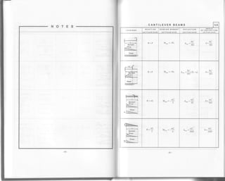
![NOTES BEAMS FIXED AT ONE END, SUPPORTED AT OTHER 3.7
LOADINGS SUPPORT REACTIONS BENDING MOMENT
IAT FIXED EtID)
R" _
3M. (L' -b')
T:
3Mo (f -b2)
--*TR=
M [ /h'?]
M"=+l l-ll , I i. when b<0577L
- L '"',1
M" =0, when b=0.577L
v =-!n[r 3f !]'.]. when b>0.5771
" 2l L/l
I Sheor
q rTITlTlTlTITlflTlT[m v2
^ 3EI
"L'
^ 3EI
"U
1FT
M =:="v
,:F4 t
"Illml| ,n"o, I
r'IIIIUIIIIIIUIIIIIIIvz
lFT
f,
- 3EI
1FT
M =--.-"t
., oc'.-
-
t--'------'+'
1l
I Moment I
I sh"o. I
Vr llMffiMfiffi vz
R ,3EI
I-2
^ ]EI
c
lFT
M =-:::
L](https://image.slidesharecdn.com/structuralengineeringformulas-160419150544/85/Structural-engineering-formulas-34-320.jpg)
![NOTES
Table 3.12
Example. Movingconcentratedloads
Given. SimPle beam, L = 30 m
q=40kN, Pz=80kN, Pr=120kN, P+=100kN, P,=80tN' Ip, =+zOttN
a=4m, b=3 m, c=3m, d=2m
Required. Compute maximum bending moment and maximum end shear
Solution. Centerof gravityof loads (off load Pr):
Bending moment
I(p, .*,)lIq = (80x++t20xz +100x10+80x14)/ 420=32801420=7 '8 m
e=z.s-(3+4)=0.8 m, el2 = 0 4 m
R. =tp xr!-9lrl = +zo(rs-0.+)/30 = 204.4 kN
^ u, ) ))
M-* = Ro [l - :l-tt, t". b) +P,r]= zsa.47 (ls - 0.4) -[40x(4 + 3) +80x3] = 2464 2 kN m
z z) -
End shear
Load P1 passes offthe span and P2 moves overthe left support
nu. =
Il u
-r, =42014 -40=*roroL30
Load P, passesoffthespanand P3 movesovertheleftsupport
n., =
It o-o-
=42otl -80=-r8.,.,
30
For maximum end shear load P2 is placed over the left support
v^ = e, +[r, (r,-b)+r, (L-b-c)+P5 (L-b-c-d)]/ L
= 80+[120x (30 -3) + 100(30-3 - 3) +80(30-3 - 3 - 2)] /30
=80+7240130=326.7 kN
-64-
SIMPLE BEAMS
o
U
J
t
I&.
ul
,U
I
v,
J
u
F
E
x
UJ
u
t
o
(.)
(9
I
o
I
3.12
E.Ea?EsIl:=:;sE:68.fi; f i'riu - I oi E H H e
e H t ;1. 5 P F e
Ite ^l-qEgE:;; il
=
3 I t65 X r E: t E
E6; -< E F !
E;Eeiisg!3E I * *: f E e g
; ; E n -l i * ; H *o * F 9:l o n
; r T Ei,I, ; Z Z H F
!EHF+#==$ E
EeE F A i E 3
;aE3
^]e5leg 'o
=
E
xE B -e e * 3
Eb
=
E E i .e
", -g
9iu-;
'<:X=
c{F s
:^Xg
;to.;:.:odo
6:^ h
3 93 E
>gE6 do
FF 6 E.
on6c
6;
.!-.=-
q P ^-
olo.
=a.Ex
:3!6
FgEEP5E E
ie; s
EE: E
xxE!
Fft!o
F-.L
i p€ 3
S EE 3
o
o
=
o
E
o
o
E
o
=
_1
ll"rT-j
f
)
E
0
.9
c
E
o
_
--t
f(
,l-
,f
lno
l-r
/
{' Eo
-9
q
t_
65](https://image.slidesharecdn.com/structuralengineeringformulas-160419150544/85/Structural-engineering-formulas-39-320.jpg)
![NOTES
FRAMES 4.1
i'l jp
F
+
Llr 'i
'ls! -
lr
,l= rl
ld>
-#ITE
tplfi+ f
i fl- j" l,,.1*9
+" ',^ ,,
-
A
H
Ll
l-{
tl
E
-fTITITITFI
;l
o
-r- a
F
+
la-
'^
1rl+
^ l1 E13
la dl.l lS
r,l+ -lY +
Elil .l
;i *tE " +
It ! I
il>ll
>ll
>
l'l N
!lr *
- Tlc lCts Tl+
T i(lr ^-l -
=
"i El- Jl
B €l- rl F
ll't .'-
. il d ^_l
* +" |
'l
Bil^i
d, l
:
}r>
.t >-
?E.E.I-v,l drf
-"-LT+EirlN*g-
lla
->
H
E
-f-FfTtTtTn
-77 -
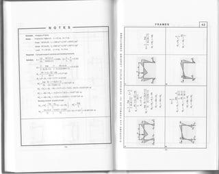
fhe formulas presented in Tables 4.1-4.5 are used for analysis of elastic frames and allow computation of
bending moments at corner sections of frame girde6 and posts. Bending moments at other sections of
frame girders and posts can be compuled using the formulas provided below'
For girders:
rr M">Md, rr,, =r3,,,-[Ytr-*1+rnr.]
tr M. <Md. rr,|,,-, =rri|!,- -[!cI4'*+v"]
lf M"=Mo=M., MeG) =M"t"t-M,
For posts:
M,(-) =M:(,) -(H t-M"or)
Where: M!,,, and Mf,-, represent, respectively, for frame girders and posts the bending
moments in the corresponding simple beam due to the acting load'
x is the distance from the section under consideration to corner c (for the girder)
andsupport aor b (foraPost).
o
z
o
=o
z
o
o
o
z
o
o
J
o
F-
F
o
o
f
o
a
o
o
J
=d,
o
lr
tt
o
U'
=
t
o
:o](https://image.slidesharecdn.com/structuralengineeringformulas-160419150544/85/Structural-engineering-formulas-45-320.jpg)
![FRAMES 4.3
I
^t
!l+
- lN +
'II T
gl E
i>
i
o
o
C
:6
F,i
d
+
;o
o
o
ul
i | >1, vi
flr qt= :ln =: ? ? g
;l-
=lJ
slr vl^ i ? Jrl or +l ,1.: s fgl ll 6l l-eE,;
>'l= f j ol#il il" j
-i.""tt.+>>r&
t
o
o
o
o
o
tl
lN
+l'j jl+
*lr rlJ l*Tl! ! | i-l
:--l o! |
Frt {l^ 3l^-. I -=l! dl-
<l- i?l =ldl* fil hl
il
tl]l " rl
r-til
+
o
t
o
o
a
NOTES
o
z
9
=a
z
o
o
o
z
o
o
J
o
;
F
o
at,
f
9
g.
o
o
J
f
=d
o
L
6
o
=
t
o
:o](https://image.slidesharecdn.com/structuralengineeringformulas-160419150544/85/Structural-engineering-formulas-47-320.jpg)
![FRAMES
NOTES DIAGRAMS and FORMULAS for VARIOUS STATIC LOADTNG CONDTTTONS 4.5
M" =-+, ru,=*9
oo
Ph ph
M"=+ -, Mo=-]
oo
PB M"=-d! t,=*+
t"=.+, M. =-+
(+Ato)Steady
tr.t. =- fll'k . o.o,ot" h'(l+k)
lr^=-1r,,r.. k=I,h'2"I,L
d = coefficient of linear expansion
22 steady heat (+Ato)
M =
3E!
I'k*,')[I-*!)o at'" h'(l+k) 2/
M.=- ffl'k fr+L)a.at'" h'(l+k) 2 )
v , =-Iv.. y. =-$r[L]"a*' 2 h'2)
M, =-M-,, k=
I'h
I'L
Cx, = coefficient of linear expansion](https://image.slidesharecdn.com/structuralengineeringformulas-160419150544/85/Structural-engineering-formulas-49-320.jpg)
![NOTES
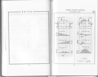
THREE-HINGED ARCHES
SUPPORT REACTIONS, BENDING MOMENT ANd AXIAL FORCE 5.1
I v-diogro.
Vertical reactions:
IM" =RoL-P(L-x")=0, n^ =rf;
IMn =-nut,+Px, =0, Ru =PlL.
Horizontal reactions:
5-rrl. =n. !-s"i=0. H^ =R. !;4 ^2fLeft
Ix=Ha-HB=0, HB=HA=H.
Section k (x.,yo)
Bending moment: Mo = lM = Rox* -Hyu,
or Mk=Ml -Hvk '
/Shear: Vu =l R'^ -IP lcosQu -HsinQ*^l^al
Letl
or Vk =Vk'cos0k-HsinQu'
Axial force: *- =[*^ -lr]s;n4o + ucosq,
kftl
or Nk = Vk"sinQk +HcosQ*'
Ml and Vou = bending noment and shear in simple beam
for section x,
Tied
c IM" =RoL-p(L-x")=s, n^ =r!b;
IMo =-R"L+pxn =0, ft" =p.5-.
Horizontal reaction:
lx=-H" =0.
Force N, :
rrra- = n^ !-^-o-r[!-*"]=0.' l? )
1.ft
N" =][pf !--" )-r
r I
' dL 2 '
t^;j
I t,t^ =N,c-n"!=g. l.l, =P-
L
.
L "2dRishr
Tables 5.1-5.9 are provided for determining support reactions and bending moments in elaslic arches
wilh constant or variable cross-sections
Table 5.'l includes formulas for computing in any cross-soction k the axis force Nk and the shear
These formulas can also be applied in analysis of arches shown in Tables 5 2-5 9
Bending moment Mr = Re xr -Ha yo +Mo -IPr 'ar
Len
Axial force Nr = Ra sinQ+ Ha cosQ -lP, sinQ
Shear Vt =Racos0-Hermq-iq"otqhft
Where ai =distance from load P to point k](https://image.slidesharecdn.com/structuralengineeringformulas-160419150544/85/Structural-engineering-formulas-51-320.jpg)
![NOTES
Table 5.2
Example. Symmetrical three-hinged arch
Given. circulararch 2 inTable52' L=20q f=4m,
4f'+t 4x4'z+20'1
radius R=-=-l;;-=la.) m, x. =) m,
-(14.s-4)=3.11m
II
tanq. = | i-x. ltln-r+ y. ; = 1t0-5)/(14.s-4+3.1 1) = 6.367
r )
Q-=20.170, sinQ. =9.345' cosQ. =9'939
Distribution load w=2kN/m
Requirod. compute support reactions RA and Ho, support bending moment MA ,
bending moment M. , axial force N. and shea
I 1 wli ?.x2o2
sorution. n^ =iwl-=ixzx2O=15 kN , n^=;;=ffi =12'5 kN
e- =I-=a=o.zs, n- =J-=
3
ll=o.zrs
L20'"f4
M, =
#Ls(€. -Ei )- 28. -n. ] ='1?o' ;t{o.,t-o'2s'z )-2x0'25-0 778] = | r' I kN m
N. = Ro sinQ. + Ho cos Q. - w. x. sin Q, = 15x0.345+ 12.5x0.939 - 2x5x0.345 = 13.46 kN
V.=Rocos0._HosinQ.-w.x.cosQ.=15x0.939_|2'510.345_2x5x0.939=0.38kN
-90-
SYMMETRICAL THREE-HINGED ARCHES
OF ANY SHAPE
FORMULAS for VARIOUS STATIC LOADING CONDITIONS 5.2
A
+Ra
LOADING9
SUPPORT
REACTIONS
BENDING MOMENTS
Ro =R" =IL
*r^=""=*
wLl,ly E2 _ |
lvrm = g L+gm-!./-'tm..l
2
Ra =aw|,, Rs =:wL
s^ =H" =iF
', =
f t'te, -€'. )-26. -n.1
r- =S{16.-n-).
#5t
..f2 *f2
*^=-;. R"=
zL
H. =-lwf,^4
H" =f*f
-,12t r ^
t. =-?[8.-ir.+ni J
Mk =?(28,k-nk)'
4
,o lP o, ,
J{A B
*^ =r?, *" =t;
H^ =H" =P*
r',r^ =r;(zle,-n,)
rtlu =e|{26,* *ttu)'
-91 -](https://image.slidesharecdn.com/structuralengineeringformulas-160419150544/85/Structural-engineering-formulas-52-320.jpg)
![SYMMETRICAL THREE-HINGED ARCHES
OF ANY SHAPE
FORMULAS for VARIOUS STATIC LOADING CONDITIONS 5.3
LOAbINGS SUPPORT
REACTIONS BENDING MOMENTS
w JIIIItrnn*
R, =:wL^ ai
'|
R- =:wL
---r2WL
n- =n^=-
48f
,.,r 2 _
u. =ft [:€. +s(8, -Ei. -8, +El )-'r.]
n- =*(zB*-n,).
wlllllnhn-, r R- =R^ =
*'
H^=n"=fr
v^ =ffPe^* a(si. -Ei. -e, * *) -n.1,
*^=-$, *"=$
H. =-awf"^12
Hu=l*t
r. =S1r{e,. -6i.)+n. -zq.]
r.=$ir€*-n*).
M- =Mol-](https://image.slidesharecdn.com/structuralengineeringformulas-160419150544/85/Structural-engineering-formulas-53-320.jpg)
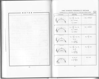
![TWO_HINGED PARABOLIC ARCHES
sEToN
ll
ll
:ii
It
riii
ill
iiir
il
iil
iii
!ii
Table 5.4
Example. Two-hingedparabolicarch
civen. Parabolic arch 3 in Table 5.4
q 5
L=20m. l=3m. x=a=5m. E=i=--=O.ZS
4f(L-2x) 4x3(20-2v5)
-^,tano=-I_=--.tr-_".'
Q- =16.70, sinQ" =0287, cos0. =0958
Concentrated load P = 20 kN
Required. compute suppon reacrions Ro and H^, bending moments M" and M" '
axialforce N- and shear V" (atpointofload)
solution. n^ -PL,
u
=zo2?-
5=tsttl
20
. -
5P!u [r - rr, *E.l = :]4j l9
x r^fo.zs - z-o.zs) +0.25"] = 10.7s kN
f,A=-KL9-zr, >.1 g>l L
v =
PL
lae - :r (a
- ra, * q* 11 =
20I 20
f +ro.zs -:(o.zs - 2x0.251 + 0.2sa) =-e.s kN m]
8 L: -". - ' lt 8 L
4f (L-x)x _4x3(20- 5)xs
- r,_t=---F--'
M, =Roa-Hny. =l5x5-10.75x2 25 = 50 81 kN m
N. = Ra sin 0" + HA cosq- = 15x0 287 + l0'75x0 958 = 14 6 kN
=Re cosO. -Hosin0* =15x0'958-l0'75x0 287=I 1 3 kN
FORMULAS for VARIOUS STATIC LOADING CONDITIONS
5.4
Equation of parabola:
4ffL-x)x
l, = | ,coso*
' 't:
-.-- dy 4f(L-2x)
t-q=d* = L'
Coefficients: Forregulararch: t=0, k:l
t5 B | ^ Er_
Fortledarch: D=- ._. K=-. D= '
8 f'. l+1). E,A,
LOADINGS SUPPORT
REACTIONS BENDING MOI4ENTS
NMIIITIIIITITITTIIITIIIITIT! W n^=R"=*
Ho =Hu =
tt1
rr.r.=$tr-t)
15
8
B1k =-
f2' ^- l+r)
3l
R.=:wI_. R-= wL
^8"8
H- =H^=-K
l6f
M. ==(r-k).lo
tt 1
M- =l--:k lwl"'" 16 64 i
I
-q
R. =P" -" R-=P:.L"L
Ho =H"
5PL. r. ^". ".r
gf L' ' ')
rra- = IL[+e -sr. (E
- 2E' + E" ).1
' 8 L - ' ' t)
.L
4
RA
5wL - wL
24"24
= H. = 0.0228 "'" k
"f
HA
M" =Rof -Hof](https://image.slidesharecdn.com/structuralengineeringformulas-160419150544/85/Structural-engineering-formulas-54-320.jpg)
![FIXED PARABOLIC ARCHES
Table 5.6
Example. Fixed Parabolic arch
Given. Fixed parabolic arch 2 in Table 5 6
L=20m, f =3m, x=€L=8-, q=]=o+, €,=t.
t=20=;t=oO
-
-....20 L 20
Distribution load w = 2 kN/m
Requhed. Compute support reactions RA and HA, bending moments Mo and M.
sorurion. n^ =fe[r+e (l+E(,)]=]?90.+[t+oo1t+o+x06)]=13'es kN
-,r ) )x)O2
H^ =
ti" e' [r + :q ( I + 2E' )] =
rJl,zY
" s +' x[l + 3x0 6( i + 2x0'o )] = I 0's8 kN
l,t. =-*t' E,E: =-2x?0' xg.+'x0.63 =-13.82 kN.m
2"' 2
T
M" =Roi-wx8x6-HAf -MA
= 13.95x10-2x8x6-10.58x3-13'82 = -2'06 kN m
sEToN
1l
l1l
I
itl
l!
iir
ll
lrii
lir
lii
Iil
llr
il
li
FORMULAS for VARIOUS STATIC LOADING CONDITIONS 5.6
+MA
Equation of parabola:
4f(L-x)x
y=
L, ' rx=lc/cos9x
. dy 4f (L-zx
'una= dx
= r
6
*Rl - L-x
-'L
LOADINGS SUPPORT
REACTIONS BENOING MOMENTS
1
M^=Mu=Mc=0
r,
-
*u Y)9j
^ 2'-
*, -
wt' rtpzrvro -
-
'
3
wt_ wi_
R^=-;, Ru=
+L
-- lt .n^ =--WI^14
u. =awf"14
M. =-
5l *f'^ 280
M- =
19
*f'" 280
M^=- 3
wft' 140
RA =qi(1+2q)P
RB =6'?(1+28,)P
H=P15Lt'e:
4f"
n. =p*eif le-rl^ " t)- l
Mu =PLB'q,
[;E
-tJ
For 03(S0.5:
rr.r-=I!e,lr-lell' t - t ,- l](https://image.slidesharecdn.com/structuralengineeringformulas-160419150544/85/Structural-engineering-formulas-56-320.jpg)
![FIXED PARABOLIC ARCHES
FORMULAS for VARIOUS STATIC LOADING CONDITIONS 5.7
LOADINGS SUPPORT
REACTIONS BENDING MOMENTS
RA
P
"2
1 sPT
H = :::-:
64f
PT,
M^ =M- =-JL
?DI
'64
w fillnnrn* w
,a
WL
R. =R^=-
., )wu
l28f
M^ =M- =- "-
192
wl- = --' 184
#,-f),B
_ 6EI.
^L"
^ oEt.
r" =* ti
-. 15 EI"
2fL
OFI
^L
]FT
"L
1EI
tvl- =--.-' 2L
-/
D _D -N
__ 45 Er,
-- 4 f)L
tvt = tvt -
ZIL
1{ FI-" "_c
' 4f L](https://image.slidesharecdn.com/structuralengineeringformulas-160419150544/85/Structural-engineering-formulas-57-320.jpg)
![Table 5.9
Example. Fixed Parabolic arch
civen. L=40nr" f=10m, xr=8m
Concentrated load in point k Pr = 12 kN
Required, Usinginfluencelines,compute supportreactions Ro and H^' suPPort
bending moment Mo, bending moments M" and M* axialforce No' and shear
x, 8 4xl0(40-8)8 ,,-
Sotution. a=l=0.2. yr =-----=b.+ m,
4f(L-2x) 4xl0(40-2x8)
-^ a
tanQ=-t-=--F-
Qr =30.960, sin0k =0 5i4, cosQu =9'357
Ro = S, xPo = 0'896x12 = 10 752 kN
r40
tt^ = S, x-l x R = 0.0960x-l:x l2 = 4.608 kN
' t lu
Me = Si xlxPt = -0.0640x40x12 = 30 72 kN m
M. = SixLxPu = -0.0120x40x12 = -5.76 kN m
Mr =Ra xr-He Yr-Ma =10'752x8-4'608x6'4-30'72=25 805 kN'm
Nr = Ra sin0r +He cosQr = 10 752x0 514+4 608x0'857 =9'475 kN
Vt =Rr cosQ* -Ho sinQ, = 19.752*0 857-4 608x0'514= 6'745 kN
104 -
sEToN
i1
ll
L
lL,
,,li
I
,ii
i
I
Irl
Itr
i,,
l]jl
{ii
Jill
fir
,illl
illll
FIXED PARABOLIC ARCHES
INFLUENCE LINES 5.9
SrxL
Infl. Line H
Infl.1Line.M"
. 4f(L-x)x
Equation of pa€bola: y = ---- -L-
dx af(L-2x)l=lc,icosor, tanQ= . =---:,
oy L'
Rn=S,xP, H=S x!"P, M=SixLxp
oRDTNATES oF tNFLUENcE LtNEs (Sr)
x
L
RA H MA Mc
0.0 1.000 0.0 0.0 0.0
0.05 0.993 0.0085 -0.0395 -0.0016
0.1 0 0.972 0.0305 -0.0625 -0.0052
0.15 0.939 0.061 0 -0.0678 -0.0090
0.20 0.896 0.0960 -0.0M0 -0.0120
0.25 o.444 0.'1320 -0.0528 -o.o127
0.30 o.784 0.1655 -0.0368 *0.0'102
0.35 0.718 0.1 940 -0.0184 -0.0034
0.40 0.648 0.2160 0.0 0.0080
0.45 0.575 0.2295 o.o'174 o.0246
0.50 0.500 o.2344 0.031 2 0.0468
0.55 o.425 0.2295 0.0418 0.0246
0.60 0.352 0.21 60 0.0480 0.0080
0.65 o.242 0.1940 0.0498 -0.0034
0.70 0.216 0.1 655 0.0473 *0.0102
0.75 0.1 56 o.1320 0.04'10 -0.0127
0.80 0.1 04 0.0960 0.0320 -0.0120
0.85 0.061 0.0610 0.0215 -0.0090
0.90 0.o28 0.0305 0.0118 -0.0052
0.95 0.007 0.0085 0.0032 -0.001 6
1,00 0.0 0.0 0.0 0.0](https://image.slidesharecdn.com/structuralengineeringformulas-160419150544/85/Structural-engineering-formulas-59-320.jpg)
![TRUSSES
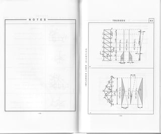
Tables 6.1-6.4 provide examples of analysis of flat trusses.
Legend Upper chord: U
Lowerchord: L
Vertical Posts: Ui - Li
Diagonals:
' Ur-Lr*t
End Posts: Lo -U'
Load on upper chord: P'
Load on lower chord: Pb
Method of Joints and Method of Section Analysis are used to @mpute for@s in truss elements without
relying on the computer. Method of Joints is based on the equilibrium of the forces acting within the joint.
Method of section Analysis is based on the equilibrium of the forces acting from either ths left or the right
ofthesection. (I*=0, IV=0, Iu=O)
The truss joints are assumed to be hinges, and the loads acting on the truss are represented as forcos
mncent€ted within the truss joints.
METHOD OF JOINTS and METHOD OF SECTtON ANALyStS
EXAMPLEA 6.1
r-IL"; L4
Pl
.5
,b
J
6d
Mambsr Jolntg Folcoa
LoU'
LoL,
Jolnt Lo
,h*
dr,
R^ =iL(pl +p,').s+(p; +p,b).4+(n'+r,b) :+
+(r; +r"').2+(r; +p5b)], RB = n^ -!(4, *r,').
lY=R^+LoU,.sinc,o =9,
L jUt = -f,o 7.io oo (compression) .
)X = -LoU, . cosc[o +LoLr = 0,
LeLt =Logr'ooroo (tension)'
U'L,
L,L,
lV=U,I.,-nf -0, UrL, =Prb (tension).
Ix=-L0L1 +LrLr=0, L,L"=LoLr (tension)
IJrL,
Soctlon 1-1
F-
-,tp
tanp=.!::,
"=fr -0, 4 =(a+2d)sincr,.
lMo = u,Lrr,'! Roa+(P,' +rf )(a + a)= o,
u,L, = f
lRAa -(r,, +ri )(a +o)]
(comprosslon or tension)](https://image.slidesharecdn.com/structuralengineeringformulas-160419150544/85/Structural-engineering-formulas-62-320.jpg)
![TRUSSES
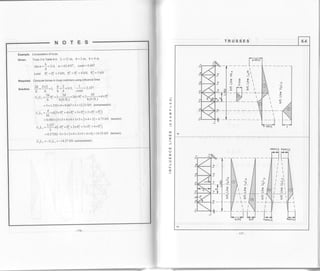
METHOD OF JOINTS and METtIOD OF SECTION ANALYSIS
Ei,A,MPLEs 6.2
Msmbor Joints Forcss
U,U,
Section 1-l (cont.)
Pt
I
l1
ryjhr
r, =(a+2d)sinB
IM", = u,urr, +RA?d -(PJ +P,b
)d = o,
u,u, = -po26 -iPI + Pi)d (compression).
U.L,
L,L,
Joint Lz
t y = u,L, - u,L, sin c, -p,b = o,
UrL, = Pro 4 Y,;-, .in 0? (tension).
lx = -LrL, +LrL, + u,L, cos c, = o,
LrL, =YrY,, -g r1-, coscl2 (tension).
(J2L3
l',L,
Sectlon 2-2 r, =(a+3d)sino,
IMo = U,L,r, - R^a + (nj +rj)1a + a)+
+(nj + el )(a +zd) = o,
u,L, =l[R^a -(pJ + pib)(a+d)-(pj +p,b)(a+2d)]
(compression).
!M,, = -L,L,h, + RA2d -(PJ +Rb)d = o,
t-,t, =i-fRoza-(rl +rf )al 6ension1.
trz'
ltrLl
r P,l =Pj, P,'=Pi, P.o =Pi, Pj =P,b,
LrLo = LrL' UoL, = UrL,
IY = UrL, - UrL, sinc, - UoL, sin cr, -Pro = 0
UrL, = Prb.r grtrr rinct, +U.L,sino, (tension).](https://image.slidesharecdn.com/structuralengineeringformulas-160419150544/85/Structural-engineering-formulas-63-320.jpg)

![SEToN
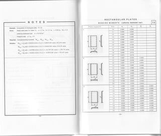
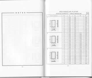
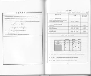
Tables 7. j-7.9 provide formulas and coefficients for computation of bending moments in elastic plates'
The calculations are performed for plates of 1 meter width
The plates are analyzed in two directions for various support conditions and acting loads'
Units of measurement: Distributed loads (u ): kN / m)
Bending moments (M): kN m/m
-120-
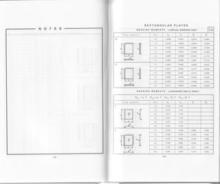
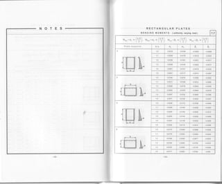
RECTANGULAR PLATES
BENDING MOMENTS 7.1
CASE A: CASE B:
a<b
caseA 9>2 Plateshouldbecomputedinone (short) directionasabeamof length L=a
a
CaseB !<2 ptatesnoutObecomputedintwodirectionsastwobeamsof lengths L,=a 5d lr=l
a
h
a
h
:>2
a
(h
Formulas for bending moments computation ,
: < 2 i
a )
Bending moments for any Poisson's ratio p:
v'" --fftr-ulr )M,", r1p -u, )M,,,].
'"i l-r_. tsT
Mo(a) =(ra w a b, Mo,o, =cro w a b
M.,", =p..w.a.b, M,,0, = po.w.a.b
Where: w =uniformly distributed load
G",do,0",Fo = coefficients from tables
for Poisson's ratio Pr = 0
Mi,) =+[(l-up, )M,0, +(p-pr, )M
",]'FT
Support condition
L e g e n d: :|rsssss
Plate fixed along edge.
Plate hinged along edge
t-------
Plate free along edge'
$f Plate supported on column
J
- 121](https://image.slidesharecdn.com/structuralengineeringformulas-160419150544/85/Structural-engineering-formulas-67-320.jpg)
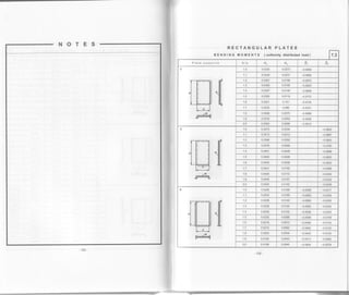
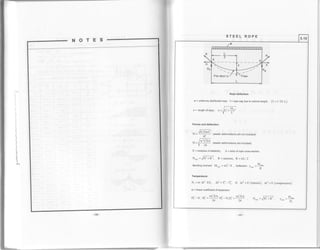
![CIRCULAR PLATES
BENDING MOMENTq St{EAR and DEFLECTrdN 1unitomiyritstriOut"O toaat 7.9,
a = circular plate's radius
r = circular seclion's radius
t =thickness of plate
MR = radial moment
.
.,
Mr = tangential moment .
V& = radial shoar ,
R =support reaction
A = defloctiqn at conJer of ptate .
trI. = Poissonls ratio
E = modutus ofelasticity ' ]
Moment, sheaf and deflection diagrams Forrnulas
p=:, p=wnaz, R=+, v* =-3p'r2ra*2M'
,]
p
V. = ^ (l+u){t-o')
" 16n'
D-
M, = j-l 3+p-(r+
lotr.
^ Pa2,. ,,/s+u ,)a=
uo*(r-o-Jl,* -o'J,
:p)p']
D= ,qc
t2(t-1t'z)
ll1
Vi
A
p=f,, r=wna R=d; y* =-zrnlp
p-
r,r_ =ftlr+u-(3+p)p,]
rr.r, =
fi [r +u - (l +3p)p,]
Pa2 , ^' Etl
^=ab('-e')' "="G')](https://image.slidesharecdn.com/structuralengineeringformulas-160419150544/85/Structural-engineering-formulas-75-320.jpg)

![SOILS
NOTES
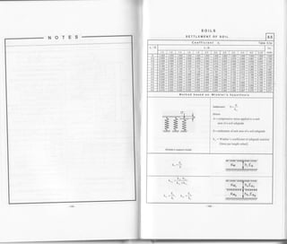
Table 8.4
Examole. Settlement of soil. Method based on elastic theory'
unirs: B(m), r(m), u(m),h,(-), P,(kN), v,(tNlm';, o" (kPa), E. (kPa)
I = weight of shuctures + weight of footing and surcharge + temporary load ( live load )
zi =distance from footing base to the middle of hi layer
Lower border of active soil zone for vertical load P" has been adopted as 20% of
natural soil Pressure: 0.2d"
oiven. B=3(m), r=s.4(n), H' =5(-), ho =2(t), h' =h' =1, =1 0(m)<0'4B
H, = 4.0(m). ho = h. = fi" = h- = 1.0(m)< 0 48
yo =Tr =1.8(ton/rn')=lz r(tNlm'), E' =40000(kPa)' F' =o'10
y, = 2.0(ton/m' ), s., = 25000(kPa)' 9z = 0'72
Engineering properties of soils are determined by field and laboratory methods
Required. Compute settlement of soil under footing
P. 3000
sof ution. op =
fr =
ffi = t 85.2 (kPa), o,o = Yoho = 17'7 2'0 = 35'4(lfa)
oa" = 6p - 6'10 = 185.2 -35.4 = 149.s(kPa), 0.2o, = 0.2xY'1,1 (ho + z, ) (kPa)
oa =dixo""' (fora' seeTable8'5a) , L/B=54l30=1'8
Ht zi (m/ - /a (xi o" (kPa) 0.2o, (kPa)
H1
0.167 0.944 141.4 8.9
0.500 o.794 1 18.9 12.4
0.833 0.561 84.0 15.9
H2
1.'t67 0.391 58.4 21.6
zs = 4'5 1.500 o.282 42.2 25.5
26 - 5'5 1.833 0.207 31.0 29.6
z- =6.5 2.167 o.157 23.5 33.3
Assume: z =6.0(m), zlB --2.0' o =0.189'
o" = 0.189x149.8 = 28.3 = 0'2c..1= 0.2(5.0x17.7+3.0x19'6) = 29'5(kl'a)
Settlement:
^
1A 0.72
S=t.0(14t.4+118.8+S+.01-Y19-r t.0(s8.4+42.2+11.0)ffi=0.0065+0.0018=0.0103(m)
SETTLEMENT OF SOIL 8.4
Method based on elastic theory
Ht7
t
l= Line or, 2 =Line 0.2or, 3 =Line o"
0oo
(Ior
co,
0os
con
0ou
a
Seftlemenl: s=io r, I
i=l Ds
Where
n=numberof h-heightlayers, h<0.48
oq - additional vertical pressue at the
mid-height of h, - layer , oa = o(,i .
oao
oa, =op-or, , or. =%ho , o" =5. B,L
cri = coefficient from Table 8.5a
Yi = mit weight of soil
& = total vertical load, B < L
B = width of footing , L = length of footing
Es = modulus of defomation of soil
)t12
0=l- -" u=Poisson'sratioforsoil' l-[
Sand: p=9.76, Sandyloam: 0=0.72
Sandy clay: 0=0.57, Clay: B=9.4
Alternative ormulas
Settlement ofloads on clay due to
primary consolidarion.
Settlement of loads on clay due to
s e c o n d ary c o n s o I i d a t i o n
S='o "[H]
l+eo' '
eo = initial void ratio ofthe soil in situ
e = void ratio ofthe soil corresponding to
the total pressue acting at midheight of
the consolidating clay layer
H = thickness ofthe consolidating clay layer
s, = c,s. log(t. /t" ) , c" = o.ot - o.o:
t. = life of the structue or time for which
settlement is required
te : time to completion of primary consolidation](https://image.slidesharecdn.com/structuralengineeringformulas-160419150544/85/Structural-engineering-formulas-80-320.jpg)
![8.7
aeF flg i ri b
?: j" li Ff ili:,;:/+7- ! ;E ro r* E
i E-L ; E e - =- - = i
aEi€i'nF =ia :IE-; E
a3i'ai-82 Ei-g; 5€g * p
lE e1€€ E * -' E i ,€:;E ;En ; ;
5E F s gtY';L EsF 3 g
q
o@
;a F
mS
d*
NF
d6 E
;fiooOU
a
U
*E
z
oODF
iiE
Rtr
eE
?z
o$
e
o
X
3-
t*
v.
EO
q^'
oo
oo
oo
LJf'ct
o
> lrL
o
r=-J1
Lt-L_ |
l_l
qqqac!
FOOoO
aU'rolcol uo!]cnpeu
g3R33e3 R gooFooin N
.{p'6y'c11'sro}3D3 F11codo3 6u1:oeg
153 -
NOTES
2
o
<
z
=(,
o.
o
=u
r!
o
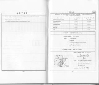
Table 8"4
Example. Bearingcapacityanalysis
civen. Rectangularfooting, B=3.6 m, L=2.8 m, BIL=1.28, smoothbase
Granularsoil, 0=300, c=0, Y=130 Lblft3 =130x0.1571=20.42 kN/m3
Loads P=2500 kN, M=500kN.m, e=500/2500=0.2m, elB=0.213.6=0.06
Bearingcapacityfactors R" =0.78, N" =20.1, N,=20
Required. Compute factor of safety for footing
Solution. q,rt=TDrNq+0.4TBNy=20.42x2x20.1+0.4x20.42>,3.6x20=1409kN/m'?
p.$.
= q,,, . B. L. R. I P = | 409 x3.6x2.8x0.7 8 I 2500 = 4.43 > 3](https://image.slidesharecdn.com/structuralengineeringformulas-160419150544/85/Structural-engineering-formulas-83-320.jpg)
![NOTES
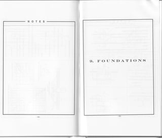
Tables 9.1 and 9.2
Example. Direct foundation in Table 9.1
Given. Reinforced concretefooting, B=3.6m, L=2.8 m, h=3 m
A= B.L =3.6x2.8 =10.08 m" s" = L.B' /6= 6.048 m3
Loads P, = P + W, +2W, = 2250 kN, M" = 225 kN m, H = 200 kN
Allowable soil contact pressure o = 360 kPa = 360 kN/m':, f = 0.4
Requir€d. Compute contact pressure, factors of safety against sliding and overturning
P
'M.
P. IM,
sotution. q^* =
o.T
q"'=
A
-=-
2250 200x3 + 225
= 223.2+136.4 = 359.6 < 360 kPaa.*=rrg+ 6ga3
q^b =223.2-136.4 = 86'8 kPa
Factorof safetyagainstsliding I-.s
P f 2250x0 4
=IE= zoo =*
'
Factor or sarety asainst overturnins . t =
H =
#jfr =
ffiffi = + s
FOUNDATIONS 9.2
DIRECT FOUNDATION STABILITY
Factor of safety against sliding; F S. = !j" )rr
P, = total vertical loaO, !U = total horizontalforces
f = coetficient of friction between base and soil
f = 0.4-0.5
Factor of safety against overturning: F.S. = Yn*'
lvro(r
J
M,1uy = P,.B/2, M.,., =M+)H.h
M.(k) = moment to resist tuming
Mo,u, = turning moment
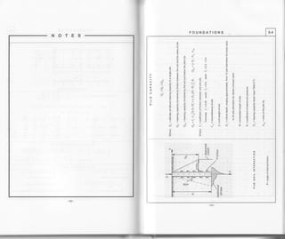
PILE FOUNDATIONS
Distribution of loads in pile group
Example 9.2a
Foundation olan and sections
Axial load on any particular pite:
o_P,-M,x-M_.yri--rilr-
' n.m - )(*)' -
l,:)'
& = total vertical load acting on pile group
n = number of piles in a row
m = number of rows of pile
M,,M, =moment with respact to x and y axos,
respectively
x, y = distance from pile to y and x axes,
respectively
Example 9.2a: n=4, m=3
s, 2 ^ ^f,^ - .2 ,- - ,21
Z(x) =2 3L(0.5a)- +(1.5a)-l= 6. 6.25a = t3.5a
)(y)'=2.+.1u;'=t6'
pirel: x=-1.5a, y=b, p,=+- NItl'5"*Yi-b-&
-M, *M"4.3 13.5a'2 8b') D 9a 8b
pire2: x=-0.5a, y=-b, &=J.-
M,0'5a-y+=&-M,-v.
4.3 13.5a2 8b'? n 27a 8b
pire3: x=0.5a, y=0, p, = +* Y:]1" * Yii0 = &*l!
4.3 13.5a2 8b2 12 9a](https://image.slidesharecdn.com/structuralengineeringformulas-160419150544/85/Structural-engineering-formulas-86-320.jpg)
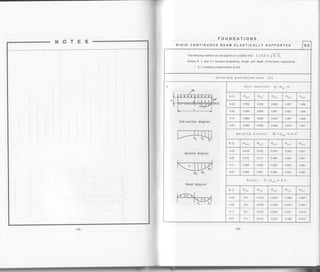
![NOTES
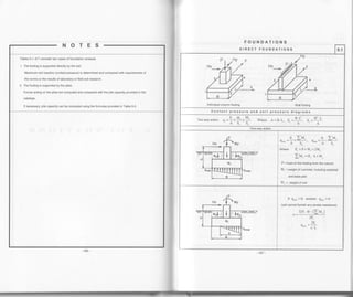
FOUNDATIONS 9.3
Distribution of loads in pile group
X
Foundation plan and sections
Example 9.2b
vl
- 'd---*- +-l - +"-
I I | ,l I
-
--r-- 4) -
-r- - . -+.
-
Axiat toad on any particutar pite: P =
P' t lL: t lL+'' n.m - I(r)' - I(vl'
n=7, m=3, I(.f=2.3 [(")'+(2a)'+(:a1']=6'14a'z =84a2
Z$)' =2.i.(b)' =vr,
Pilel: x=-2a, y=0. R= : -:. Y':'o= I -
M'
' 1.3 84a' 14b' 21 42a
pitez: x=0, y=-b, p,= + - Yr,o - $}= & - M-
' 7.3 84a' 14b' 2l l4b
pile3: x=3a, y=b, &= + * Yi ?' - YL,o= +. p. *' 7.3 84a' 14b' 21 28a l4b
Maximum and minimum axial load on pile:
p M v n(n+l)a.m m(m+l)b n
D=u+l+ls=',s=',-ffi n.m-S"-S"' 6 -Y 6
1t1+ta.'t 1(1+lh.7
lnexampleg.2b: S = ' /" -
=28a. S =--
-'-
=l4b-' 6 6
'-
PILE GROUP CAPACITY
Ne = Ee n'm No
Converse-Labarre equation :
/ e (n-l)m+(m-l)n
E- =l-l : I'
' 90,/ n.m
For cohesionless soil Es = 1.0
Where Ne = capacity of the pile group
Ee = pile group efficiency
Np = capacity of single Pile
0 =mctand/s (degrees), d = diameterof piles,
s = min spacing of piles, center to center](https://image.slidesharecdn.com/structuralengineeringformulas-160419150544/85/Structural-engineering-formulas-87-320.jpg)
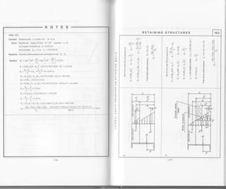
![For determining the lateral eadh pressure on walls of structures, the methods thal have proved most
popular in engineering practice are those based on analysis of the sliding prism's standing balance'
The magnitude of the lateral earth pressure is dependent on the direction of the wall movement. This
correlation is represented graphically in Table l O l . The three known coordinates on the graph are
,Po and Pe. As the graph demonstrates, the active pressure is the smallest' and the passive pressure
the largest, among the forces and reactions acting between the soil and the wall
construction experience shows that even a minor movement of the retaining walls away from the soil
in many cases leads to the formation of a sliding prism and produces active lateral pressure
RETAINING STRUCTURES
LATERAL EARTH PRESSURE ON RETAINING WALLS 10.1
Correlation between lateral earth pressure
and wall movement
Po = lateral earth pressure at rest
P" = active lateral earth pressure
Pr = passive lateral earth pressure
Ko, K", Ke = coefficients
Coefficients of lateral earth pressure:
K0 = coefficient of earth pressure at rest: Ko = 5 = . !
6 t-tr
md o" = lateral and vertical stresses, respectively
Poisson's ratio
Type of soil p
Sand 0.29
Sandy loam 0.31
Sandy clay 0.37
Clay 0.41
Alternative formulas: Ko = 1- sin O - for sands
Ko = 0.19 + 0.233 log (PI) - for clays
Where PI = soil's plasticity index
Where Oh
P'n
Coulomb earth pressure
^ ^ -r, ,12
r" =U.)l("Ylt, rn=U.)reyH
Where Y= unit weight of the backfill soil
t, [.1q-b),t'(o-p) 1
L'-t/*.t";st."lP:O]
K" = coefficient of active earth pressure
Kp = coefiicient of passive earth pressure
Coulomb theory
K"=
cos'(q-cr)
cos'zo.cos(c+6)
cos'(4-a)
Ko=
cos'o.cos(o-6)
Q = angle of internal friction of the backfill soil
6 = angle of friction between wall and soil (6 = 2 /30)
p = angle between backfill surface line and a horizontal line
G = angle between back side of wall and a vertical line
t, F'(o.s)'t"(a+p)l
l'-/-.(CI-D).".(P-")l
EARTHQUAKE
cos'(q-o-cl)
e = arctan
lkn / (1 - k" )]
kh = seismic coefficient, kh = AE I 2
AE = acceleration coefficient
k =vertical acceleration coetficient
-173.](https://image.slidesharecdn.com/structuralengineeringformulas-160419150544/85/Structural-engineering-formulas-93-320.jpg)
![ry
NOTES
Table 10.2
Example. Retaining wall 1 in Table 10.2, H = l0 m
Given. Cohesivesoil, angleoffriction Q=26''
Cohesion c=150 lb/ft'] =150x47.88=7182 Pa =7.2 kN/m'?
Unit weight of backfill soil Y = I l5 lb /ft
r
= 1 l5x 0 1571 = 18.1 kN/ml
Required. Compute active and passive earth pressure per unit length ofwall: Pn, h, Po, do
Solution. Active earth pressure;
K =ran'[+s" 9l=tun i+5' 4l=o.ro
2t l. 2l
pn = K"FI - 2cf<* = 0.39x1 8. lxl 0 - 2x7.2JdJ9 = 61.61 kN/m
PnH 61.61 l0
= 8.73 mL_
P" = 0.5prh = 0.5x61.61x8.73 = 269 kN
Passive earth pressure:
K, - ran, | 4s, + I 1-,un' I or" *
20"1-
z.so'-p " r 2) [ 2,]
pn = KoyH + 2c= 2.56x 1 8. 1 x 1 0 + 2x1.2JL56 = 486.4 kN lm
e. = u.s f :. run I or' * ! I * o, I n = 0.5 [23.04 + 486.41x10 = 2547.2 kN
' L 2/ '"j
nr++"tun[+:'+]l
d.=------,.-.-H=
:ln,+z.u"l+s +9]l
486.4+ 4x7 .2>1.6
xl0=3.48 m
3f486 .4 + 2x7 .2xl .61
RETAINING STRUCTURES
LATERAL EARTH PRESSU RE ON RETAINING WALLS 10.2
Rankine earth pressure
= 0.5K.^/H' Pn = o.5KD
-1Ll-
Rankine theory ({[=0, 6=0)
The wall is assumed to be vertical and smooth
,, ^^_ocosB-r/cor'p-.os IK"=cosp+- cosp+ /cos'B cos'q
Kp=cosF?
cosp- p-cos'q
If o=0, 6=0 and 0=0:
K- =
1* sin O
= tan'[or' -9')" l+sinO 2)
K- -
I fsino-,un,l,+:o*d)= |
' l-sinO 2l K,
Exam les
't. Assumed: a=0. 6=0. B=0
2cVTE
l-f
N7 N---t'
Aq'AlI^-j+t_;_t-R/
2q V .Kp
-t-l--
AA
LH)
Cohesive soil
A/ Active earth pressure
pr =K"yH-2cd!
Where c = unit cohesive strength of soil
r,=u,"f+s"-ll. n= o'n
zt p,+z.r-l+s"-fl
2.)
Resultant force per unit length of wall P" = 0.5pnh
B/ Passive earth pressure
p', = KnyH - 2.Jrq . r, = un'[+5" 1'9
]
p- = o.sfz.tunl+s' *91*o. l. t' L 2t '')
A-
n, ++" t*[+s'+9J
:[n, * z" ,uoi+s'*9ll
2 ))](https://image.slidesharecdn.com/structuralengineeringformulas-160419150544/85/Structural-engineering-formulas-94-320.jpg)
![RETAINING STRUCTURES 10.4
+ >-l >-
T =l;;"?ll
Er!
!4 El
i, pil
--l
d oilori
EEo
o
llll
FFc
!2. !2" Ehh
;:x
ilil=
ai o-i E6
5
-a
E}F-F r g
XME
llll;
o'd3
o
6
o
o
o
Er6 -e-
rr F .sl
o!-;:;il
le+;-+10."
;F6RiiuloL;+o.-lo€:,i"1 =rtL.;€z--!?-
e V - +l N _l- E !
sv].-f+gr;oYo'83Lilll !?:g
d -- ,s, 3 6.
o*--;-+€
o.E-9E
'-: - s -lN g
:ia+t.-e--6d*6
<V}ZY;-
ilil"^S .o
d-F
-'179.
NOTES
o
!
I
:I
llJ
u
t
o
lu
a
3
o
tt
u,l
E
A
F
E
!J
E
u,
F
J](https://image.slidesharecdn.com/structuralengineeringformulas-160419150544/85/Structural-engineering-formulas-96-320.jpg)
![RETAINING STRUCTURES 11.1
N
a
l^E-.-tl o
! E >1.>- T
" Edld >
^-: f slH
'"]r rr 3 Il:
o x t!
'- c ni E il: o'
q e o P 6lE +
r^r E : a EIE *
* .1 I :ole" hl
F. e E 3 EIE _t
,.t H ii 5tE a
I f E EIT A
F. * "P
--,1,-
Frl
o ', 9
;3
t-
lA
ol99t.o
ul I
',=t F
3tP
IE
--tF-
+t+
r ElE
:srl-Poil-ilE
;.od ;" 1>to-o
:Fo-:=r-.F6;lqs-'l
-cbxlE
c:_-6r!>
ilAE
> ij g -:_ -.. t.: B > el N..el^,3
oE.bE'n="^
o Q E;.w li o €
-Egii-:--E---,8U, g gE- E =* F e
:6E+h:F
-o*kFdF
g;3 3 e 3
ttii.=t3tl
3t€ a" I e.'
o
o
.9
b
'il
Hlr
'^lL
€l
+
Ft4
Nl.r
E
;
o
o
o
o
E
.E
o
F
N
'l la
VI
>lx
htlN
I
.rlN
E.
o
c
E
o
I
E
U
ao
o
(
q
o
o
o
o
o
o
9)
I
o
E
e
a
ll
q
-185-
NOTES
at,
J
J
B
o
=2
:F
U
t
g.
IJJ
lu
J
;z
(J](https://image.slidesharecdn.com/structuralengineeringformulas-160419150544/85/Structural-engineering-formulas-99-320.jpg)
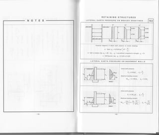
![RETAINING STRUCTURES
NOTE
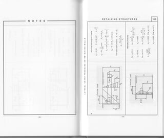
Table 11.2
Example. Cantilever sheet piling 2 in Table 11.2, H = l0 m
Given. Soil properties: Q, =32", c, =0, Tr =18 kN/ml
Q, =340, c, =0, % =16 kN/m3
K,.Y,H 0.283lgyl0
-r--
(K" - K. )Yr 3.254x t6
P, = 0.5K"^1,H2, = 0.5x0.283x1 8x 10x0.98 = 24.96 kN,
P -0.5(Ke K,.)y,(Do-2. )': =0.5x3.254yt6(Do-2,)
IVto = O (condition of equitibrium)
',
(f .o,).', (o, -]) -* Jro, -,,) = o
zzo.:[f +r.]+z4.e6Do *26.031(Do -2, )' = 0
8.68(Dn - z, )' = 921.0 + 301.26D o
Using method of trial and error:
assume Do =8.3 m, (8.3-0.98)' =t96.16*rO..'tx8.3, 394.19 =393.18
D = l.2Do =1.2x8.3 =9.96 m
r.- = t [+., *,,)* v,(?
",
*,,
)
- o.s
1r,, -
"^.l
r*Z(?)
= zre.: ($ + o.rs * t.+)* z+.0 e(l"o.n, * r.o) - o. r', zs+ xr e xs +, (!l =' rn r.o u*
B=0, o(=0, 6=o
per unit length of sheet pilingRequired. Compute depth D and maximum bending moment M,."*
sorution. K' ="''(or'-!)=
'*'(*" -!)=,ro,
r", = tm'[+s' -9.) =
""'[or' -1L] = o,"
r", = tm' (+5' n Q,
)
="',(or, *fj =r.rrt,
P, = 0.5K,,T,H' = 0.5x0.307x18x10'? = 276.3 kN,
CANTILEVER SHEET PILINGS 11.2
Equation to determine the embedment (D0 ) :
- (r,-r,)vrir
6(4H+lD[
Maximum bending moment :
/
-
| 1t p I
M."=P[H+;iG;fi]
^ 4H+3D
-' -'oH +4o,
For single Pile
o-(K,-K-)YdDi r- =.f"n?' 3{4H +3D") [ 3
where d=pilediameter
D = (1.2 to I.4) Do for factor of safety at 1 5 to 2 0
'(Kp;Ko)T2Qo-74
Earth pressure:
R = 0.5K"^YH'
P: =o.5K,,YrH z' zt=
P, = 0.5(Ko. -r", )T, (Dn -,,)'
Equation to determine Do: lMo = 0
ef {*o,l*e,f o.-11-e jro,-, t=o
3 ") - 3l
D =(1.2 to 1.4)Do for factor of safetyat 1.5 to 2 0
m = point of zero shear and maximum bending moment
Maximum bending moment
(H ,(2
*.- = R
[;.
z,+ zz
)+P,l:z'
+ zz
)
(,
-os(r,-r")rzi [5J
186 -](https://image.slidesharecdn.com/structuralengineeringformulas-160419150544/85/Structural-engineering-formulas-100-320.jpg)
![w-
NOTES
Tablo 11.3
Example, Anchored sheetpilewall in Table 11.3, H=15 m
RETAINING STRUCTURES
Given, Soil propedies: 0, =30', cr =0, ^L=20 kN/m3, 02 =320, cz =0, T, =18 kN/ml
Requrred. compute deprh D ano
'*,'r.lJ"oo,"n"rl"l""i;t:* ,:,;fi"Tn-
",",Solution.
r", = m' f +s' -9 l-,un' f +s' -4)=o.rrr, K. = tan' | +s' -9 1 =,-, i +r" -14 I = o.ro,"' 2) 2 ) ( 2l '-
[- z)--"
K,. =r*'f +so+91=,un'[+:"*14 ]=r.rro, K", -K,. =2.s48
"' 2) l. 2 )
Forces per unit length of wall
P, = 0.5K",T,dt = 0.5x0.333x20x1.2': = 4.8 kN
P, = 0.5K", y, (H + d) (H - d) = 0.5 x 0.333 x20x (rs + r.2) (r s - 1.2) = 744.4 kN
. (H -d)(2H +d) {r5 - t.2 )(2x t5 + 1.2 )
' 3(H+d) 3(ts+t.2)
p:
=0.5K",rrHz, =0.5x0.307x20x15x1.74=80.13 kN, , =#HE =o'r!#frirt =r.r,
Fot Q2 =32' : x = 0.059H = 0.059x15 = 0.885
Ivr, = o, R(H-d+x )+r, 4-p,a, -p, (H-a-1) = o
R(r5 -1.2+0.885 )+ +sx! -t ++.+x8.86-80.13fl5-r.r* t tol
= o, R = 527.46 kN
3 z ) -'
T = (Pr + P, + & ) - R = 4.8 + 744.4 +80. l3 - 527.46 = 301.87 kN
o"=r, * i|,,E =, ro*.@=7.58m. {assumed
V(K' -K..)Y,, Y2c48xl8
D= l.2Do =1.2x7.58=9.1 m
i e,+e,+e.-r /4J+i44l+sot3-jot-87
, _-
! 0.5(Ke - K" )y, Y 0.5v 2.948x 18
r.* = (q *r,)(4*,, *,,) *r,(2,,*".)*r(+r-d+2,+2.)-0s1r," -r", )i,* (f)
= {
+. s + za.+; (ll + t.t a + +.+6)+ Bo x(}t.t + * +.+al - ro,.r, 1
r, -,., + 1.7 4 + 4. 46)
-0.5x2.g48xt8x4
46'
= 2019.4 kN .m/m
o
=ul
J
;
F
u
lll
a
U
o
z
s' slo
+
-
i ^i+.1
*-l:'
^i bT.
B E --l- )z
qP"i;
:!+aGl, l
> X I 19 Nl-
; : tFt-j-- Nl
E E tit .,
J E l'"ll oi
9 : l+lr +
6El^^li^
E -lTlv.. N
t E l'-|tr; I* F +F +
-oNl'":.
F+
,9b;o,-
^IEE-
xc
.!6
"nxEn-o<Htr>d
o
E
g
ll.,
I l>tl^
lo< | Fa
lel I
lli
I lv-
+
N
I
a
^lil':
N.'",
il Nilo a
x+
o il
-
ll
- E ----
er^.| r -
!.. E V
(d,b
or{c 'Ft,. 9
E^-O
h':o
o:
!xE
9+c
*+o:F
ffsL
I
o
I
o
T
ts
ci
N
-
d
N
I
N
o
Nl^
',''
=lJv ;l I
v't vl .
rr ll4
oiil
_Nl
F,z
> -l O
.- it o
V Jl- e
d Nl+ X
^^ Yl; g
it o
EII F
*d B
VEv] .- -a
,,,'rl
or-dx
o
E
u
N
o
o
.N
I
:a
if,Y](https://image.slidesharecdn.com/structuralengineeringformulas-160419150544/85/Structural-engineering-formulas-101-320.jpg)
![TUNNELS
I-
NOTEST R E C TA N G U LA R C R O S S- S E C T IO N 12.2
rtFI
FI
F
F
H
f
llh-i(
l2(k+l)
Mo =M" =lfo ={"
For k=l and h=L
M" =M. =M^ =M, =_I::
24
Mo = o.l25ph' - 0.5 (M" + Md )
M., -M" -- Ph't(2k+7)
'"b o0(k, +ak+l)
M -M, -- P!'!(lk+S)
60(k':'4k+3)
For k=l and h=L
M'=M,=-lPh'. M-=M --llph/160 480
uo = o.o64ph'? -[M" +0.s77(Md -M" )]
-L2t.
a =
P" I ltotr' -:u'I60h'
^ pbak (. 45a -2b D=:-n-_a-_b-_l
2h' 270a )](https://image.slidesharecdn.com/structuralengineeringformulas-160419150544/85/Structural-engineering-formulas-104-320.jpg)
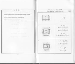
![PIPES AND TUNNELS
Table 12.3
Example. Rectangular pipe 7 in Table 12.3
Given. concreteframe, L=4m, H=25 m, hr =10 cm, h, =lQ s6
b =1 m (unit length ofpipe)
- bhi looxlor bhi loox2or
l.= J=--EJJJCm lt=-=- =OOOO/Cm
'1212"1212
Uniformly distributed load w = 120 kN/m
Required. Compule bending moments
- I.H 66667x2.5
Sotution. k=I='--'" - -
=5.0, r=2k+1=2x5+1=11
I,L 8333x4
m = 20(k+2) m = zo(k+2)(6k' +6k+l) = 20(5+2)(oxs' +oxs +t) = zs:+O
or = 138k2 +265k+43 = 138x5'] +265x5+43 = 4818
o, = 78k'? + 205k + 33 =78x52 +205x5 + 33 = 3008
oc: = 81k2 + l48k + 37 = 81x5'? + I 48x 5+37 =2802
r. = - 9l l* o'
l= ''o-10' I
t.
*-1!lL]= -22.56 kN.m , M.
' 24[r m) 24 ll 25340]
M.=_:fr1*s.l=rro_10'r+._rgol)=*,u.rr^ -, Ml
' 24r m) 24 !ll 251401
y", =_wL'f
:t<+t
*a,_t20ta'z(l"s+ 2802
)__125.2 kN.m
"' 24 r m) 24 ll 25340)
= -
*f f 1- ", ) = +7.e2 kN.m
24 r m)
=-*f 1,1- "'J=+2.24 kN.m
24 r m)
*",=-9[U-b)=-roz.++r<n m. Mno
"' 24[ r m)
M . =-r{ g.
--l2ox4:.
ee2
=-6.24 kN.m
"' 12 m 12 25340
M . =_
*L' f
3k*t _gr) _ _r20x4' [:xs+t r
qqz']
=_l19.44 kN.m
"" 24 r m) 24 ll 25340)
=-*f .
*,
=-17.76 kN.m
12m
R E C TA N G U L AR C R O S S_S E C TI O N 12.3
Th
I'L
r =2k+1
m=zo(k+z)(6k'+6k+1)
+M =tension on inside of section
r2
Ir Ir
l.
r2
l2
4 I1
tv
ffi wti t
,^=-i ;, M. = M. = M, = ,{.
..,t2 tl+l
r, =-li -'';'. Mo,=Moo=Mu.=Vo,
lt -^t -n
M"
wf-'f t o, ) .. sL rt cr, l
r. tvl =-- _-
-
i
24r m) ' 24r ml
=-'"l,]*c'1. 1r4.=-"1'i1-o, 1
24r m) 24lr n)
wL'z/3k+1.a, .. wL'c,+jNl,
24 r m) "' l2 m
_ wt-'(:l*t cr,) n, wL' cro
r. i,_ =--
-24t r m) "' 12 m
wt-'l.lt<+t . o, 1
lvri< = --l" 24[ r m)
," wL'l:t<+t o,)lvi,, = --l' 24 r m)
M.
Mn,
Mo,
dr =138k' +265k+43, tlc3 =81k' +148k+37
c: = 78k'?+205k+33, cx4=27k2 +88k+21](https://image.slidesharecdn.com/structuralengineeringformulas-160419150544/85/Structural-engineering-formulas-105-320.jpg)
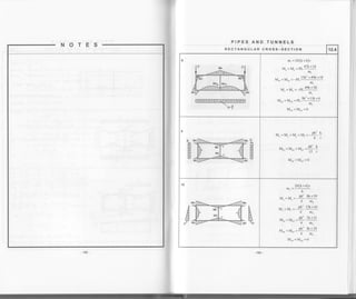
![TUNNELS
R ECTAN G U LAR C ROS S-S E CTI O N 12.5
p
t-{
F'
t-l
E
crr = l20kr +278k'?+335k+63
ct2 =360k1 +742k'? +285k+27
03 = 120kr + 529k2 +382k+ 63
cr" = l20kr +61 1k'z +558k+87
!p <r?h
4
m=zo(k+2)(6k
y =Ph'f-
2
*o, l," 241 n, m)
y =-Ph'[
2
*o, ]," 24|n, m)
v", =-Ph'i,
1
*o, l,"' 241 n, mJ
., _ ph'( t,*,)
r
+bK+l l. n, =
^^ _ph'( 2 0, )
' 241 n, m)
^" - Ph'(2 o'l
' 24[n, m)
M,.=-Ph'f -
I
-o, I"' 24( n, m)
^, -
ph'f I ool
24fn,'^)""'- 241n, my
^h1
ry
^h2
o
4 . =-Ij-.:1. Vl ,. =!--.:l"'12m"-12m
1
+
P h2/6
I
A
E
p9
a, =24kt +50k2 +99k+21
az = 144k3 + 298k'] +l 09k + 9
crr =36k3 +169k'? + 120k+21
crcr =36k3 +203k' +192k+29
m -20(k +2)(6k'z +6k+l),
",
=Ill:g]j
M. ptr'( st<+sq,a, )
M. 24 l. n2 n)
M ph'ftzL+ot, c,)
Mf 24 n2 -n)
7k+31 , o. )
n2 -^)
M, ph'I zt+3t , a. )
M,, 24 n2 m)
Muu _ pht (:t+zl - cro l
M. - ,4 l. ,r, ';,
M.. =-d s.. u.. =
Ph
tz m tz
Mo,
--Pht
Mo, 24
c[1
m](https://image.slidesharecdn.com/structuralengineeringformulas-160419150544/85/Structural-engineering-formulas-107-320.jpg)
![PIPES AND TUNNELS
CIRCULAR CROSS_SECTION 13.1
: b.=a5'
,u /+v
:- +M =tension on inside of rang
+ Tension
- Compression
0.=90'
I +N
b= 1 3s'
I
l-0.=t gd
Loading condition c=900 cr = 135" a=1800
M +0.25wR'? 0 -0.25wR'? 0 +0.25wR']
N 0 -0.5wR l.OwR -0.5wR 0
0 -0.5wR 0 +0.5wR 0
M -u.r)pK 0 +0.25pR'? 0 -0.25pR?
-l.0pR -0.5pR 0 -0.5pR -l.OpR
0 +0.5pR 0 -0.5pR 0
M 0.208pR' -0.029pRr +0.25pR' +0.029pR' -0.292pR1
T
-0.625pR'? -0.41 2pR' 0 -0.588pR'? -r.J /)pK'
0 +0.41lpR'] +u. tl)pK- -0.589pR' 0
M 0 0 0 0 0
N -pR -pR -pR -pR -pR
0 0 0 0 0](https://image.slidesharecdn.com/structuralengineeringformulas-160419150544/85/Structural-engineering-formulas-108-320.jpg)
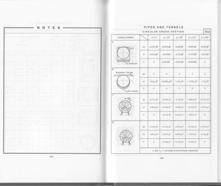
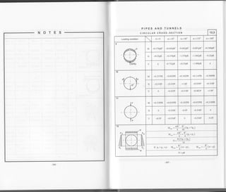
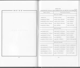
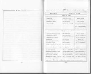
![r-
NOTES-
-216-
MATHEMATICAL FORMULAS
ALGEBRA M.2
A LG E B R A IC E X P R E S S I O N S
(alb)'?=n'?+23616' 3r-U']=(a+b)(a-b)
(a +b)' - ar +3a2b+3ab'] t br sr +63 =(a+b)(a, Tab+b')
(a+b)' = n" *
a
u",6*
a(n-l)
u",6, *
a(n -1) (n2a" 3b3
+...b"
a" - b" = (a -U)(a"-r +a"'b+a" rb':
+...+ab'" +b" I
)
ALGEBRAIC EQUATIONS
Linear eouations
a|x +apy+afz = br
Third-orderdeterminants: a2x+a22y+a2rz=b1
L3rx + a32y + allz *- bl
D, D. D.
x=:t v=-. z=-
D D- t)
arL.a22.alr -al . ar. a)11
at2.a2l.alt -412.a2t.aI +
all.42 432-aB.a22.a3
I
o, u,, u,,
D, - j b, a,, a,,
I b. a,, a.,
Determine D. and D, similarly by replacing the y- and z- columns by the b- column
Equation of the 2nd degree
xt+px+q=g
Equation of ihe 3rd degree
xt+u2+bx+c=0
xr =Yr
a
3
,. ir /.
Determinant: D=l " i -l f L o- b--
l/ 21 l
2^lq=-a --a.b+c
a
If D=0: y,=i[4q, ,,=r.=E
a
- -' 3
-l-iJJ - t-i"6Il u:u: c0,=-- . o.=
-
'22
1-- ) --rf D 0: v, =iJ:/lpl co'e. r,-i.6J,orcs{q+t20'), v,-j'6ld-'1e ru0")
I -J,/Jqq= arccos- _H](https://image.slidesharecdn.com/structuralengineeringformulas-160419150544/85/Structural-engineering-formulas-115-320.jpg)
![MATHEMATICAL FORMULAS
GEOMETRY
SOLID BODIES
M.4
zoneofa Sphere
v =In(:a'+:t'+tr')
A, =n(zrh+a'+b')
A'" = Znrh
Ungula
v = 3.'h
3
a, = .t. +
] ( t' +../t' . h'-
)
A,, =tdh
sliced Cylinder
v = 1d'n
4
A, =rr[hr +h, +r
r^ -- J I
+./r'+(h, -h,l l4l
A," =rdh
Barrel
v=an(zo'+a')
12'
PLANE ANALYT c cEOMETRY (Equations)
Lin€
Y =lu+b
6 =&-!L = 1un,
Xr -Xt
, ,t , . .2
(x -a., +(y-bJ =r
If a=0, b=0:
x2+y2=1'
X, V,
a- b'
"
= 16'-d
c
e=*<l
a
x' y'
a- b-
. =rF *d
c,
a
Parabola
2
II
2TF---rJ'
Af
v=-x(L-x)-L-](https://image.slidesharecdn.com/structuralengineeringformulas-160419150544/85/Structural-engineering-formulas-117-320.jpg)
![-222
MATHEMATICAL FORMULAS
TRIGONOMETRY M.5
BASIC CONVERSIONS
sino, I I
ranc=- | seco=
-cosd I cosd
sin2c+cosr0=l | -1-=t*,untoI cos cx
cosd I I
cotd-- I cosecC=
sln0 I slnd
tand.cotcr,=l | =]-=t*"ot'oI sln c[
sin (c+P) = sin0 coso.tcoscr'sin B
tan cttmBtanldtbl=' " l+tm0.tilp
cos (cr + P) = sss 61. cos P T sin o. sin P
COt aX c()t t1 + |
cotl0:tbl=
cot0tcotd
sin 2c[ = 2 sin d.cos 0 ^ 2tan0,
tan zG - :----
-I - lan- fl
cos 2cr = cos' ct -sin2 d ^ cot'z0,-l
cotlfi=-
2cota
sin 3cr = 3 sin cr - 4sinr cr ^ 3tancr-tmro
IanJCI=-
1-3tan'a
cos3d=4cos3u-3cos(x ^ cotr 0,-3cotct
cotj(x=-
JCOt- 0 - |
. c[ sind l-coso,
2 l+cosd sincr
t-cosct
l+coscl
ct
cos =
2
cr sinc I l cosc li+.*a
2 1-coscr sinc l-cosc
. ^ {I 0, --- 1
sln ct = lsln-.cos
2 2 l+tunrl
2
-c[ztan ^
.)tan0= -
' r0| - lan-
2
' )Ul - lrn_
.0 ta '- )cosO-cos --sln--:
_
2 2 l+tanr0
z
.c)(
cot- - l
cot(x = 2
z col
2
^ a-B o-BSlnc{ r Slnp=Zsrn-.COS
2
u+B d-Rcoso +cosB - 2cor - r '.6t "i--r
'22
sina-sinB=2sssgj-q
. c-0
2
.. 0-p 0-BCOSct-COsP- 2Stn-
sin(at0)
lanc{ttanlJ=-' cos cr.cos [3
^ sin (B+a)
cototcotlj= " '
' sino sinp
- 223](https://image.slidesharecdn.com/structuralengineeringformulas-160419150544/85/Structural-engineering-formulas-118-320.jpg)
![MATHEMATICAL FORMULAS
TRIGONOMETRY M.6
BASIC CONVERSIONS
sinc co5P=151n{o-B1+]sintcr P)'22 ^ tan 0(+ tanB
tan0 tanb=-' cot0+cotp
.oro .orB = -l.os(u +B)- ] cos(o-BJ'22 ^ cot0.+cotB
cot(x cotP=
tan tI+ tanP
sin u.sinB = lco,(o-9; -]cos(o +0)'22
^ cot{x+tmB
coto(.tanLt=-' tan(x+cotB
cos or,+ sin cr = J7.sin (+so + or)
cos2c -sin:B-q6s1a+B1 cos(o p) cosa-sina =
'D
cos(+50 +cr)
ct') 0' 30' 1<0 600 90'
c[(rad) 0.0 ! = o.szza
6
! = 0]8s4
4
L =t.0472
3
I = r.sros
2
sin d 0.0 ! = 0.s000
2
t;
2
t;
-
= lJ-6bbt)
2
1.0
cos c[ 1.0
.A: = 0.8660
2
h
T= 0.7011 I = 0.5000
2
0.0
tm(x 0.0 f =o.rrro
3
1.0 Ji =1.7321 t&
cot cl r,5 = 1.7i2 I 1.0 f =r.rrro
3
0.0
(p
-o( 90'1 cr 180'+d 270" + a 160' - a
sm9 -sln d +cos 0 + sin Cx cos cl -smc[
cos q +cos(x + srn c[ -cos0 tsin 0 + cos cl
tan I -tmcr +cotd ttan o( +cot d -Ian 0
cot q - cot 0{ +tand t cot cr + tan o[ -cot o[
- 225](https://image.slidesharecdn.com/structuralengineeringformulas-160419150544/85/Structural-engineering-formulas-119-320.jpg)
![T
NOTES
SYMBOLS s.1
A Area, Cross-sectional area (cm2 )
R Supportreaction (kN), Strength (MPa)
Radius (cm)D Diameter (cm). Force (kN)
E Modulus of elasticity (MPa)
Forsteel: E=2.l05MPa
S Settlement (cm)
S Elastic section modulus
about the neutral axis (cmt)E, Modulus of defomation of soil(MPa)
{ Centritugal force (kN) S" abour Lhe x - x axis (cm )
G Shear modulus ofelasticiry (MPa) S" " aboutthey-yaxis(cm3)
For steel: G =77221MPa S, " aboutthez-z axis (cm3)
H Horizontal support reaction (kN) To Temperature (nC, "F)
I Moment of inertia of section
about the neutral axis (cmo)
V Shear (kN). Volume (cm'.m')
w weight (kN)
l, about the x - x axis (cm') Z Plastic section modulus (cmt ) , Force (kN)
[, " about the y - y uis (cmo )
c Cohesion (Pa)
" aboutthez-zaxis(cm*) e Eccentricity (cm)
ln Polar moment of inertia (cm- )
g Gravitational acceleration (S = 9.8Im/sec'])
Kn Coeffrcient ofearth pressure at rest i Radius of gyation (cm)
K" Coefficient ofactive earth pressure k*. Winkler's coefficient of subgrade (tNlcm')
Ko Coefficient ofpassive earth pressue n Porosity (%)
K, Coefficient ofseismic aclive eanh pressure p Horizontal disrributed load (kN. m)
L Spm length (m) w Vertical distributed load (kN/m)
M Mass (kg) o Direct stress (Pa)
M Bending moment
about the neutral axis (kN. m)
r Shear stress (Pa)
z" Shear strength (Pa)
M" " aboutthex-xaxis(kN.m) y Unitvolume weight (kN/m3)
M, " aboutthey-yaxis (kN.m) p Poisson's ratio
M. " about the z - z uis (kN .m) c Coefficient of linear expansion (l/grad)
Mo Dynamic bending moment (kN.m) p Unit mass (kg)
N Axial force (kN) A Deflection (cm)
P Applied load (kN) Q Argle of intemal fiiction
Q Euler's force (kN) tanO Coefficient offriction](https://image.slidesharecdn.com/structuralengineeringformulas-160419150544/85/Structural-engineering-formulas-120-320.jpg)

This document provides formulas and diagrams for analyzing stresses in structural elements under different loading conditions, including: - Tension and compression from axial forces, with stresses proportional to force and inversely proportional to area. - Bending from applied moments, with maximum stresses at the outer fibers proportional to the moment and section modulus. - Combined bending and axial load, where stresses are the sum of those from each loading individually. Principal stresses are calculated. Diagrams show variation of stresses across sections under different loads, and maximum allowable stresses are checked against code requirements. Examples are provided to demonstrate calculating stresses in a beam under bending and axial loads.


![Part 1[Autosaved].pptx](https://cdn.slidesharecdn.com/ss_thumbnails/part1autosaved-221102081148-b5d4b037-thumbnail.jpg?width=640&height=640&fit=bounds)


