
Recommended
More Related Content
What's hot
What's hot (20)
Similar to Mechanics Of Solids- Stress Transformation in 3D
Similar to Mechanics Of Solids- Stress Transformation in 3D (20)
Recently uploaded
Recently uploaded (20)
Mechanics Of Solids- Stress Transformation in 3D
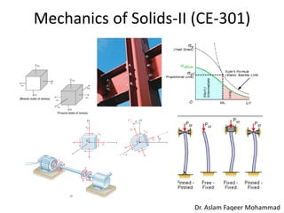
- 1. Mechanics of Solids-II (CE-301) Dr. Aslam Faqeer Mohammad
- 2. Academic Calendar 2015 FALL SEMESTER / TERM Classes Start 27th July, 2015, Classes End 13th November, 2015 Examinations Start 16th November, 2015 Examinations End 5th December, 2015+ Announcement of Results Latest by 24th December, 2015 Winter Vacations 7th to 27th December, 2015 2
- 3. Time Table for Section-A 3
- 4. Time Table for Section-B 4
- 5. Time Table for Section-C 5
- 6. Mechanics of Solids Mechanics of Solids-I Mechanics of Solids-II Advance Mechanics of Solids 6
- 7. CE-301-Mechanics of Solids-II Tentative Course Outlines 1. INTRODUCTION (Basic Concepts and Terminologies) I. Overview II. Types of stresses III. Determinate/Indeterminate Structures 2. ANALYSIS OF STRESSES AND STRAINS DUE TO I. Axial/Bending/Twisting and Shear Forces II. Combine effect of axial, bending and twisting forces 3. STRUTS AND COLUMNS I. Euler, Rankine and other formulae for buckling loads II. Stability analysis of column under eccentric loading 4. ELEMENTARY THEORY OF ELASTICITY I. Equilibrium and compatibility equations II. Biaxial Stresses III. Stress and deformation relationship IV. Stress transformation 5. THEORIES OF FAILURES I. Tresca’s Yield Criterion II. W.Rankine’s Criterion III. Von Mises Yield Criterion 6. COMPUTER BASED ANALYSIS 7
- 8. Grading • Homework/class assignments • E-Tests • Midterm (9th week) • Final Exam 8 Text/Ref Books
- 9. Course Learning Outcomes (CLO’s) 1. To get an exposure of biaxial bending and its application 2. To understand the problem of stability of column and design of steel column 3. To get the knowledge of different types of failure theories and its applications in mechanics of solids 9
- 10. Terminologies 10 Stress: Stress is the intensity of the internal force on a specific plane passing through a point. Mathematically, stress can be expressed as
- 13. Terminologies 13 Normal Stress: The intensity of the force or force per unit area acting normally to section A is called Normal Stress, σ (sigma), and it is expressed as: If this stress “pulls” on the area it is referred as Tensile Stress and defined as Positive. If it “pushes” on the area it is called Compressive Stress and defined as Negative.
- 14. Terminologies 14 Shear Stress: The intensity or force per unit area acting tangentially to A is called Shear Stress, τ (tau), and it is expressed as: Deformation: Whenever a force is applied to a body, its shape and size will change. These changes are referred as deformations. These deformations can be thought of being either positive (elongation) or negative (contraction) in sign as shown in Fig. Strain: The elongation (+ve) or contraction (−ve) of a body per unit length is termed Strain.
- 15. Terminologies 15 THERMAL STRAIN When the temperature of a body is changed, its overall size will also change. In other words, temperature change may cause the dimension or shape change in the material. More specially, if the temperature increases, generally a material expands. Whereas if the temperature decreases, the material will contract.
- 16. 16 Terminologies
- 17. Ductile Vs Brittle 17 Notice that for the ductile material, show on the left, larger strains occur before ultimate failure. In reality this means that (a) the material has a chance to change its shape in order to redistribute loads, and ( b) if redistributing the loads does not prevent failure, there is often adequate visual warning (sagging beams, etc.) before failure occurs. For these reasons, ductile failure is preferable to brittle failure.
- 18. Stress-Strain Relationship Hook’s law 18
- 19. 19 Tensile-Test FIGURE: (a) Original and final shape of a standard tensile-test specimen. (b) Outline of a tensile-test sequence showing different stages in the elongation of the specimen.
- 20. Types of Analyses 20 There are two types of analyses (Linear/Nonlinear), • Linear static analysis (without inertial forces) • Linear dynamic analysis (with inertial forces) • Nonlinear static analysis (without inertial forces) • Nonlinear dynamic analysis (with inertial forces)
- 21. Types of Loads according to Member Behavior 21
- 22. Types of Loads 22 Gravity Loads (Dead/Live Loads) Lateral Loads (1) Wind Load (2) Fluid/Water Load (3) Earthquake/Seismic Load
- 27. Application of different Supports 27
- 28. Biaxial Bending 28 Columns are usually subjected to two bending moments about two perpendicular axes (X and Y) as well as an axial force in the vertical Z direction (see Figure)
- 29. State of Stresses 29 (a) plane stress in sheet stretching; there are no stresses acting on the surfaces of the sheet (studied in MOS-I). (b) plane stress in compression; there are no stresses acting on the sides of the specimen being compressed. (c) plane strain in tension; the width of the sheet remains constant while being stretched. (d) plane strain in compression; the width of the specimen remains constant due to the restraint by the groove. (e) Triaxial tensile stresses acting on an element. (f) Hydrostatic compression of an element.
- 30. 30 Plane Stress-state of stress in which two faces of the cubic element are free of stress. For the illustrated example, the state of stress is defined by State of Stresses
- 31. Stress Transformation Equations 31 If we vary θ from 0° to 360°, we will get all possible values of σx1 and τx1y1 for a given stress state. It would be useful to represent σx1 and τx1y1 as functions of θ in graphical form.
- 32. Mohr’s Circle for Plane Stress 32
- 33. 33 Sign Convention Before the transformation equations are derived, it is necessary for us to review the sign convention for the normal and shear stress components. As shown in Fig. below, the sign convention can be remembered by simply noting that positive normal stress acts outwards from all faces and positive shear stress acts upward on the right-hand face of the element. Sign convention of stress components
- 34. 34 Sign Convention for Mohr’s Circle Notice that shear stress is plotted as positive downward. The reason for doing this is that 2θ is then positive counterclockwise, which agrees with the direction of 2θ used in the derivation of the tranformation equations and the direction of θ on the stress element. Notice that although 2θ appears in Mohr’s circle, θ appears on the stress element.
- 37. Application of Principle Stresses/Failure Theories/Yield Criterion 37 Maximum-shear-stress criterion: Distortion-energy criterion: σmax −σmin = Y (σ1 −σ2) 2 +(σ2 −σ3) 2 +(σ3 −σ1) 2 = 2Y2 Plane-stress diagrams for maximum -shear- stress and distortion-energy criteria. Note that s2 = 0.
- 42. 42 Example.#.01
- 43. 43 Example.#.02
- 44. 44 Example.#.02
- 45. 45 Example.#.03
- 46. 46 Example.#.04
- 47. 47 Example.#.04
- 48. 48 Example.#.04
- 49. 49 Example.#.05
- 50. 50 Example.#.05
- 51. 51 Example.#.05
- 52. 52 Example.#.06
- 53. 53 Example.#.06
- 54. 54
- 55. Principal Stresses by Stress Tensor Approach 55 Principal stresses and Stress Transformation
- 56. 3D State of Stress 56
- 57. 3D State of Stress 57
- 58. 3D State of Stress 58
- 59. 3D State of Stress 59
- 60. 3D State of Stress 60
- 61. 3D State of Stress 61 How to calculate principal stresses in 3D elements
- 62. 3D State of Stress 62 How to calculate principal stresses in 3D elements
- 63. 3D State of Stress 63 How to calculate principal stresses in 3D elements
- 64. 3D State of Stress 64 How to calculate principal stresses in 3D elements
- 73. 73 Principal Stresses and DCs
- 74. 74 Note: In above equation l, m, and n are direction cosines (DCs). For s1 these l, m and n becomes l1, m1 and n1 and DCs for direction vector N1 which is normal to the principal plane 1. Similarly, l2, m2 and n2 are DCs for direction vector N2 which is normal to the principal plane 2. l3, m3 and n3 are DCs for direction vector N3 which is normal to the principal plane 3. Principal Stresses and DCs
- 75. 75 Relationship b/w DCs and Principal plane angles = cos a1i + cos b1j + cos g1k = l1i + m1j + n1k = cos a3i + cos b3j + cos g3k Here a1 = 71.6 degree While b1 = 18.4 degree g1 = 90.0 Here a3 = 18.4 degree While b3 = 71.6 degree g3 = 90.0
- 77. 77 How to calculate of DCs In above equations replace value of s by s1 and l, m, and n by l1, m1 and n1.
- 78. 78 How to calculate of DCs
- 79. 79 How to calculate of DCs
- 80. 80 How to calculate of DCs
- 81. For Direction Cosines 81 Alternate way to calculate DCs (lmn)
- 85. 85 Lecture.#.06
- 86. 86 Lecture.#.06
- 89. 89 Mean and Deviator Stresses Tm = Mean Stress Tensor Td = Deviatic Stress Tensor Lecture.#.06
- 94. 94 Lecture.#.07 Failure Theories Fig-02 An axially loaded member consider to be safe if the applied stress is less than the yield strength (sy) of the material. Fig-01 Yield Criteria for Ductile Material Since this state is different from the state of uniaxial stress, it is not possible to predict from such a test whether or not the structural element under investigation will fail. Some criterion regarding the actual mechanism of failure of the material must be established that will make it possible to compare the effects of both states of stress. To this effect in upcoming slides to present the two yield criteria most frequently used for Ductile materials.
- 115. 115 Lecture.#.07 Failure Theories Example-#-01 The state of plane stress shown occurs at a critical point of a steel machine component. As a result of several tensile tests, it has been found that the tensile yield strength is sY = 250 MPa for the grade of steel used. Determine the factor of safety with respect to yield, using (a) the maximum-shearing stress criterion, and (b) the maximum-distortion- energy criterion?.